

AIM AT1604 Datasheet

AT1604
)
5-Bit Synchronous-Rectifier PWM Controller
Features
˙Drives two N-channel MOSFETs
˙Operates from +5V and +12V input
˙Simple single-loop control
-Voltage-mode PWM control
˙Fast transient response
- High-bandwidth error amplifier
- Full 0% to 100% duty ratio
˙Excellent output voltage regulation
- ± 1% over line voltage and temperature
˙TTL-compatible 5 bit digital-to-analog output
voltage selection
- Wide range 1.3V
- 0.1V binary steps from 2.1VDC to 3.5V
- 0.05V binary steps from 1.3VDC to 2.05V
to 3.5V
Dc
DC
DC
DC
˙Power-good output voltage monitor
˙Over-voltage and over-current fault monitors
-Does not require extra current sensing element
˙Small converter size
-Constant frequency operation
-200 kHz free-running oscillator programmable
from 50 kHz to over 1 MHz
Applications
˙Power supply for PentiumTM, PentiumTM Pro,
PowerPC
˙High-power 5V to 3.xV DC-DC regulators
˙Low-voltage distributed power supplies
TM
and AlphaTM Microprocessors
General Description
The AT1604 provides complete control and
protection for a DC-DC converter optimized for
high-performance microprocessor applications. It is
designed to drive two N-channel MOSFETs in a
synchronous-rectified buck topology. The AT1604
integrates all of the control, output adjustment,
monitoring and protection functions into a single
package.
The AT1604 includes a fully-TTL compatible 5-bit
digital-to-analog converter (DAC) that adjusts the
output voltage from 2.1V
increments and from 1.3V
steps. The precision reference and voltage–mode
regulator hold the selected output voltage to within
± 1% over temperature and line voltage variations.
The AT1604 provides simple, single feedback loop,
voltage-mode control with fast transient response. It
includes a 200kHz free-running triangle-wave
oscillator that is adjustable from below 50kHz to
over 1MHz. The error amplifier features a 12MHz
gain-bandwidth product and 6V/μs slew rate which
enable high converter bandwidth for fast transient
performance. The resulting PWM duty ratio ranges
from 0% to 100%.
The AT1604 monitors the output voltage with a
window comparator that tracks the DAC output and
issues a Power Good signal when the output is
within ± 10% of the targeted value. The AT1604
protects against over-current conditions by
inhibiting PWM operation. Built-in over-voltage
protection triggers an external SCR to crowbar the
input supply. The AT1604 monitors the current by
using the r
of the upper MOSFET, which
DS(on
eliminates the need for a current sensing resistor.
to 3.5VDC in 0.1V
DC
to 2.1VDC in 0.05V
DC
2F, No.10, Prosperity RD. II, Science-Based Industrial Park, Hsinchu 300,Taiwan, R.O.C.
Tel: 886-3-563-0878 WWW: http://www.aimtron.com.tw
Fax: 886-3-563-0879 Email: service@aimtron.com.tw
Preview the document, detail datasheet contact to our service department.
AT1604
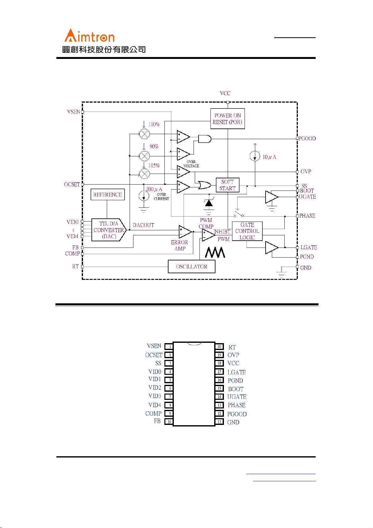
Block Diagram
5-Bit Synchronous-Rectifier PWM Controller
Pin Configuration
AT1604 (20-Pin SOIC)
2F, No.10, Prosperity RD. II, Science-Based Industrial Park, Hsinchu 300,Taiwan, R.O.C.
Tel: 886-3-563-0878 WWW: http://www.aimtron.com.tw
Fax: 886-3-563-0879 Email: service@aimtron.com.tw
Preview the document, detail datasheet contact to our service department.
 Loading...