

Page 1
Ailunce HS1 User’s Manual
1
Ailunce HS1 USER’S MANUAL
Page 2
Ailunce HS1 User’s Manual
2
Preface:
This manual is for the HS1 transceiver, a good color tft display
screen for it and good trx. As an open-source SDR (Software
Defined Radio), both in terms of Software and Hardware. As such,
the features of this transceiver will continue to evolve and this
manual is intended to provide a reference source.
Main Features
• Spectrum Dynamic Waterfall Display
• Multiple Working Modes:Receive Mode, Transmit Mode,
TUNE Mode, VFO Mode, SPLIT Mode
• DSP Digital Signal Processing Noise Reduction
• Automatic Notch Filter
• Receive Fine Tuning Function, Changeable MIC Gain Value
• VCC Power Supply Voltage Indication Table
• Transmit Signal Strength Display Table
• Multifunctional Instrument:SWR Standing Wave Ratio Meter,
AVD Audio Frequency Meter, ALC Signal Modulation Meter
Parameter:
Frequency Range
RX:0.5MHz-30MHz
TX:0.5MHz-30MHz
Output Power
Maximum 15W
Receiving Sensitivity
Better than -115dBm
Operating Mode
Full Modes
Operating Voltage Range
DC 9-15V
Dimensions
190mm*69mm*45mm
Maximum Current
3.5A
Transceiver comes with automatic key generator circuit, Can
be connected to the use of automatic keys.
Page 3
Ailunce HS1 User’s Manual
3
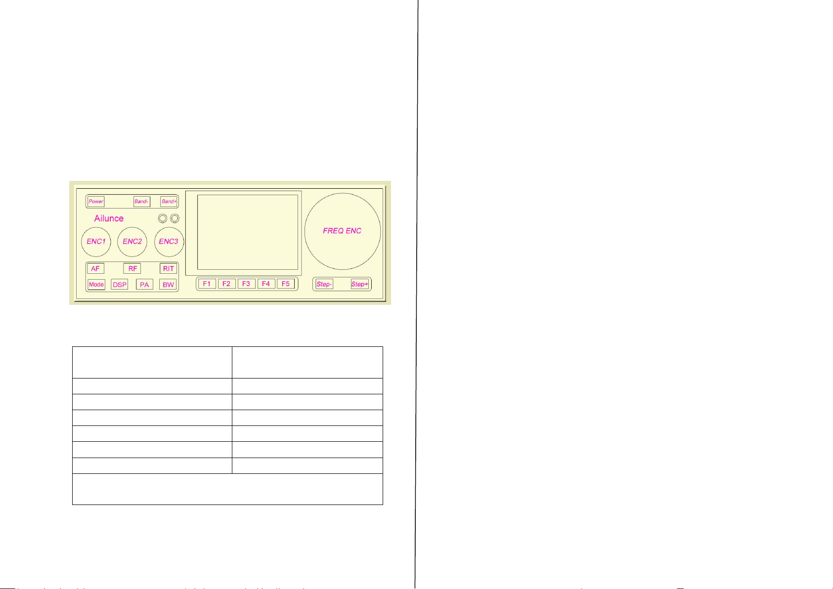
Figure 1:Front panel controls of the HS1 transceiver
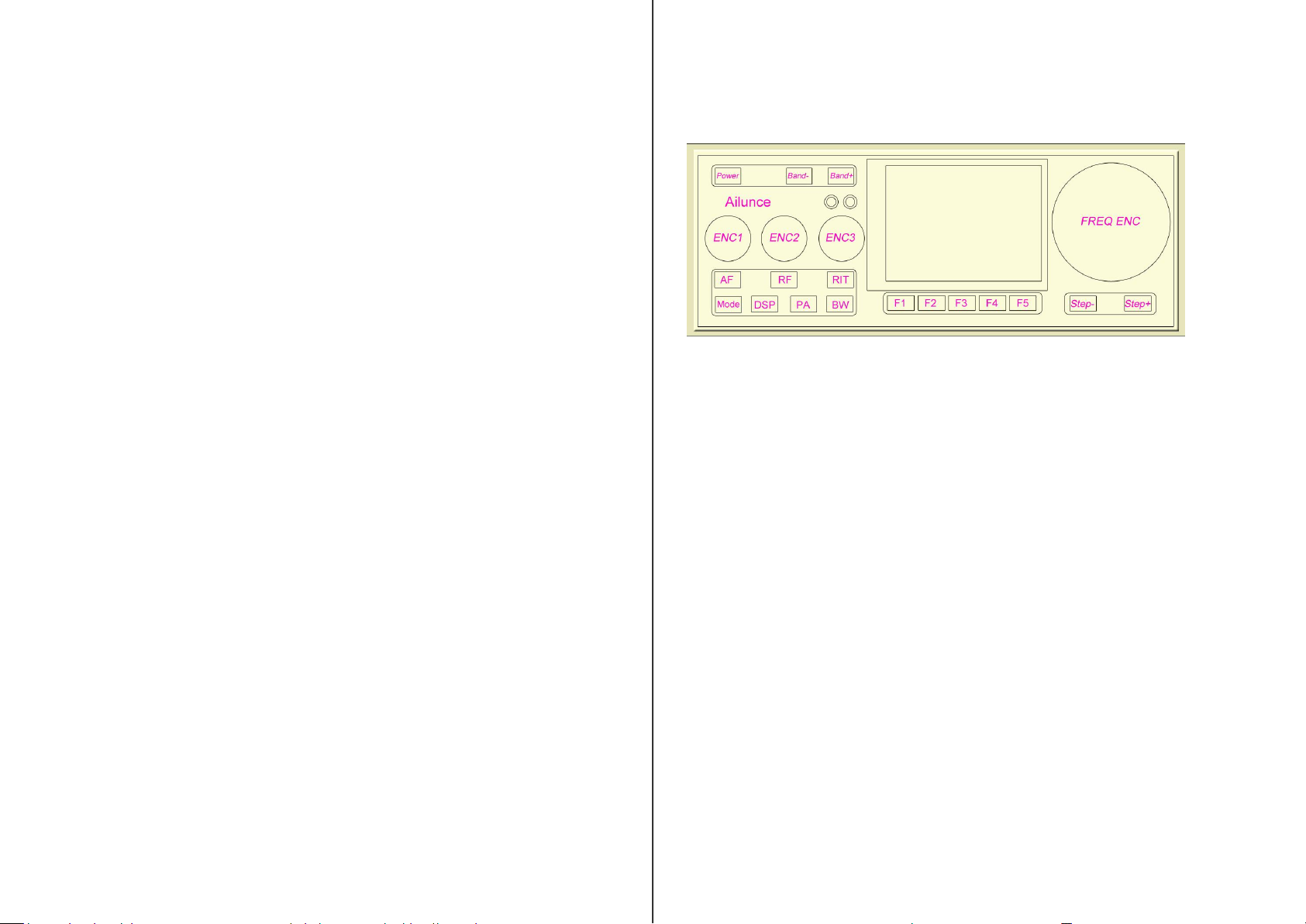
Power ~ This turns the transceiver on, but it is also used to turn
the transceiver off and save configuration and frequency
mode/memories. A brief press of this button will also select the
brightness of the LCD backlight. Please read notes about the
backlight and the possibility of its injection of a tone into the
receiver when a “dim”mode is selected. Low brightness will
cause the noise inside the machine to increase, and there is no
such noise at 100% brightness.
Important:
If you have not already done so, please find the menu
item “RX/TX Freq Xlate” and set it to “RX Low LOW”
as this will improve receive and transmit performance.
See this item's menu description in this manual for more
details.
Band-, Band+ ~ These buttons select the next lower or higher
amateur band. When the lowest or highest band is reached it
“wraps around” to the highest/lowest band. Pressing and holding
the Band- along with the Power button may be used to turn
on/off the automatic backlight blanking feature while pressing
and holding the Band- and Band+ buttons will toggle between
the display of the Spectrum Scope and Waterfall Display
STEP-, STEP+ – This sets the tuning step size in steps that
include 1 Hz, 10 Hz, 100 Hz, 1 kHz, 10 kHz, and 100 kHz. The
function of these buttons may be swapped via a menu setting.
Pressing and holding of one of these buttons will temporarily
change the step size to facilitate tuning in smaller or larger steps
while pressing-and-holding both of these buttons simultaneously
will toggle “frequency lock” on and off, with “on” being
indicated by the main Frequency readout being displayed in
grey.
FREQ ENC – This is used to tune the transceiver's operating
frequency, the tuning steps being set by the STEP- and STEP+
buttons.
ENC1,AF – Rotary encoder ENC1is typically used to adjust the
volume, but its function may be changed using button AF to
adjust the side tone gain
ENC2, RF – Rotary encoder ENC2 is typically used to adjust
the RF gain (or squelch in FM mode but its function may be
changed using button RF to adjust the action of the DSP Noise
Reduction or Noise Blanker strength. In the Menu mode it is
Front Panel controls:
simplicity they are typically defined as follows:
All of the controls are defined in software, but for the purpose of
Page 4
Ailunce HS1 User’s Manual
4
used to select the item to be adjusted. Pressing-and-holding
button RF when in normal (non-menu) receive mode will
switch between the right-hand function adjusting the DSP Noise
Reduction or the Noise Blanker “strength.”
ENC3, RIT – Rotary encoder ENC3 is typically used as an
RIT (Receiver Incremental Tuning) but its function may be
changed using button RIT to adjust the sending speed (in Words
Per Minute) in the CW mode, or to adjust the Microphone or
Line-In gain in voice mode. In the Menu mode it is used to
modify the item selected, or button RIT may be
pressed-and-held to select whether Microphone-In or Line-Input
mode is active and to be adjusted.
Mode – This button is used to select the operating mode of the
transceiver (CW, USB, LSB, etc.) Pressing this button cycles
through the available modes.Pressing-and-holding this button
will allow the selection of a mode that is disabled in the menu
system (e.g. AM.)
When “LSB/USB Auto Select” is enabled, pressing button
Mode will skip the sideband that is not appropriate for the
frequency of operation (e.g. USB will not be selected below 10
MHz) but pressing-and-holding this button when LSB is
displayed will change the mode to USB – and
Pressing-and-holding again will change it back to LSB. When
menu item “LSB/USB Auto Select” is enabled, in order to
change to AM you must select a mode other than LSB (or USB)
– such as CW – and then press-and-hold button Mode - AM will
then be selected.
DSP – This button is used to control the DSP audio filter mode.
Pressing-and-holding will turn DSP on/off while preserving the
current settings. Pushing this button will also “reset” the DSP.
PA – This button is used to set the transmit power level (FULL,
5 Watts, 2 Watts, 1 Watt, 0.5 watts, and back to FULL.)
Note: The power is automatically limited to 2 watts in
AM Transmit mode. When in CW, LSB or USB mode
(those modes with a “BFO”) pressing-and-holding this
button will cause a tone with a frequency equal to that
of the CW sidetone and transmit shift to be sounded.
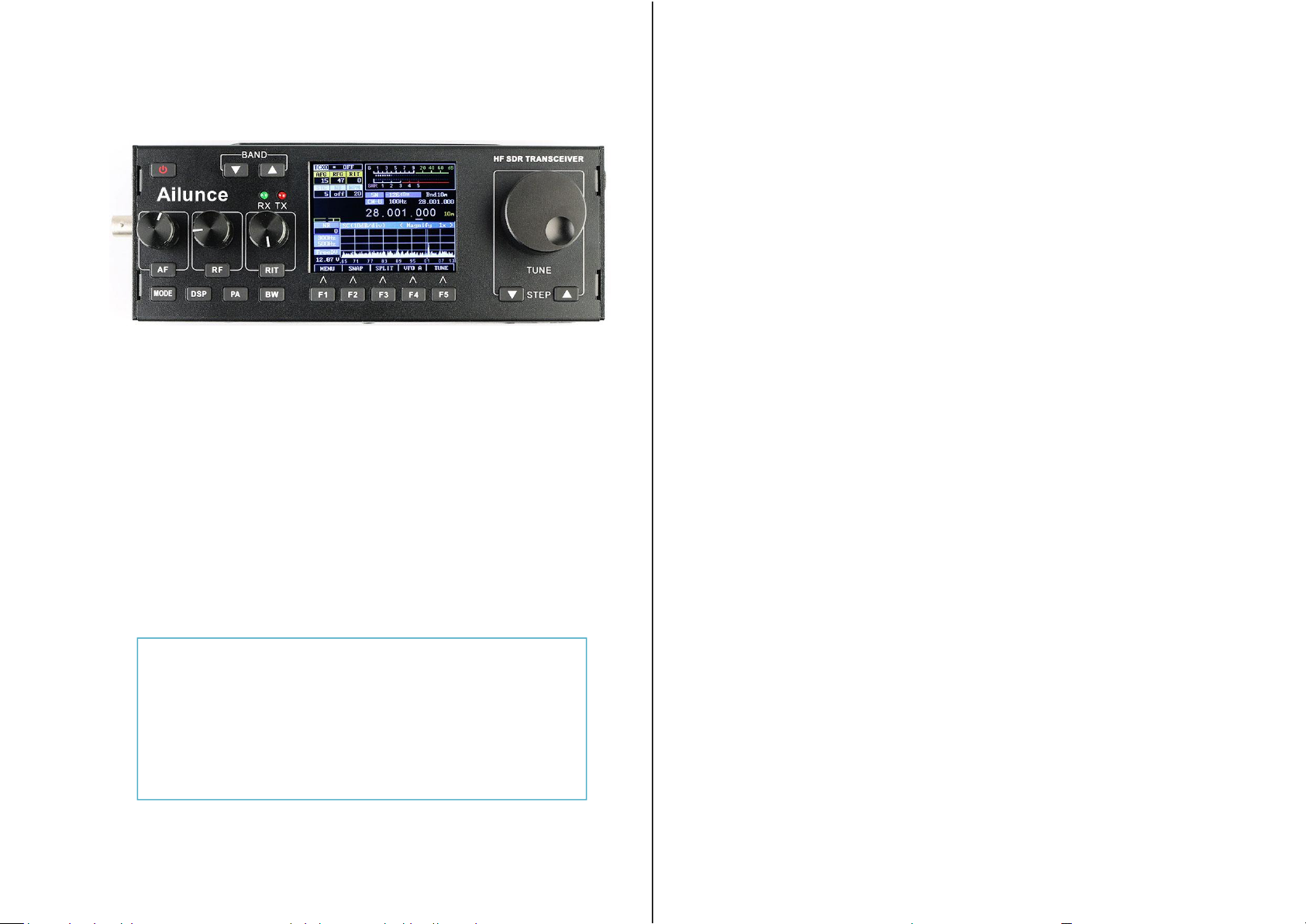
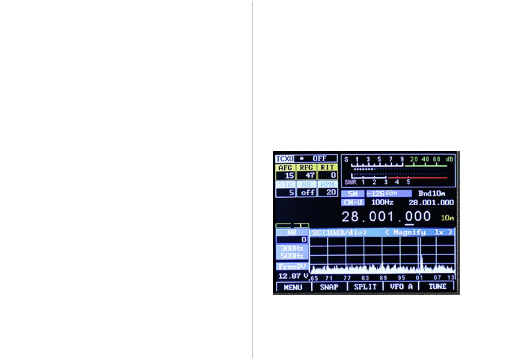
Figure 2: Main display of the HS1 transceiver
Page 5
Ailunce HS1 User’s Manual
5
BW – This button is used to select the audio pass band filter of
the receiver. Pressing-and-holding this button will force the
selection of bandwidth that are otherwise disabled. The
filter-selection function of this button is disabled when the FM
mode is selected, but pressing-and-holding it while transmitting
on FM will cause a tone burst to be generated, if this feature is
enabled.
Buttons F1-F5 are “soft” buttons located under the display, the
functions of which change depending on mode, indicated on the
LCD itself and will be discussed in more detail later in this
document.
Also on the front panel are two LEDs, LD1 on the left and LD2
on the right. LD1, which is typically green, is illuminated on
receive and LD2 which is typically red is illuminated on transmit.
Main Display:
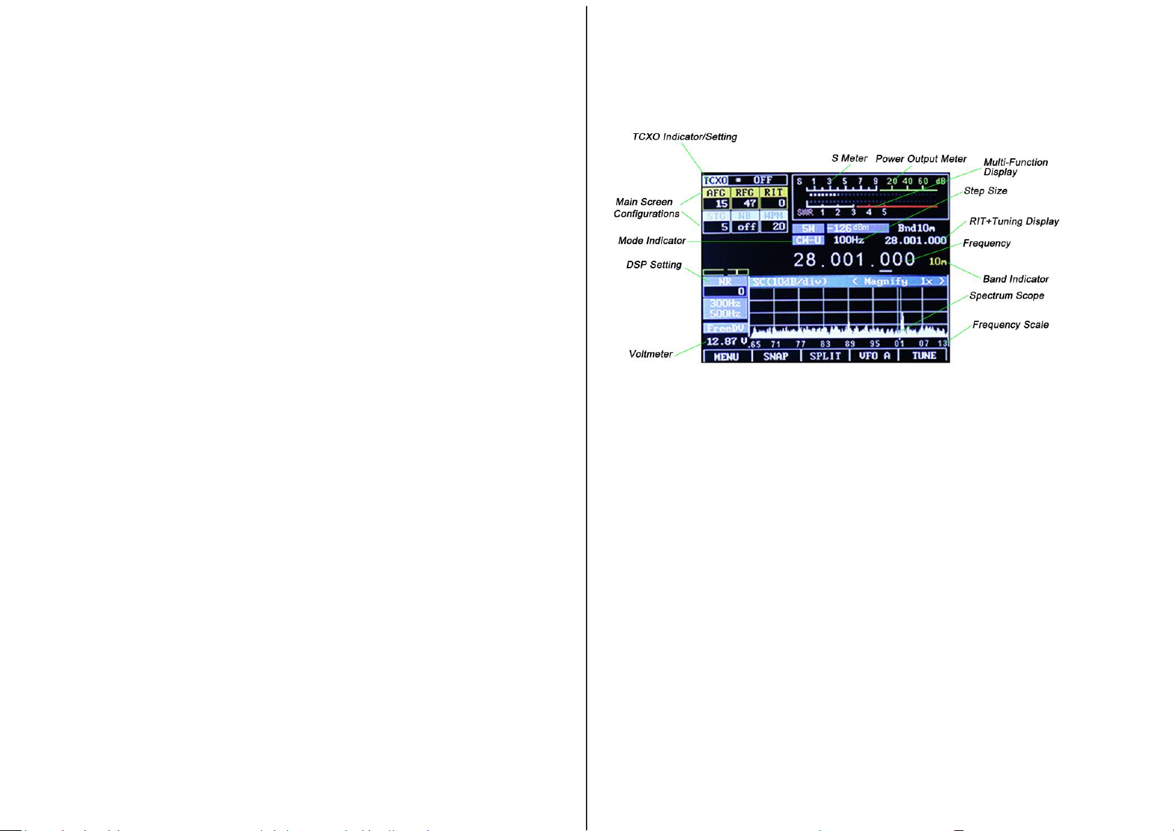
Figure 3: The main screen (annotated) with the SPLIT function activated.
When “Frequency Translate” mode is on, the center frequency indicator
will be shifted to the left or right of center by 6 kHz.
On the main display, just above the Spectrum Scope, there are a
number of indicators:
• Main Frequency Display: This may be displayed
either as a single frequency (transmit/receive as in
Figure 2) or as a “Split” display as shown in Figure 3
with separate transmit and receive frequencies. If the
numbers in this display are grey the “Frequency
Lock”(toggled by pressing-and-holding both the STEP-
and STEP+ buttons simultaneously, or configured in
the menu)is active. If this display is yellow, a
transverter offset has been configured.
Page 6

Ailunce HS1 User’s Manual
6
• RIT+Tuning Display: Above and to the right of the
main frequency display is a smaller display that is offset
from the main display if the RIT is set to something other
than zero.
• Band Display: To the right of the main display is an
indicator of the amateur band in which the current
frequency is tuned. If the current frequency is outside an
amateur band it will display “Gen” (e.g. “General
Coverage”).
• Mode Indicator: Above the “10's” digit of the main
frequency display is the current mode displayed on a blue
background.
• Step Size Indicator: Above the center of the main
frequency display, between the Mode Indicator and the
“Sub” Frequency display is the setting of the current step
size. In Figures 2 and 3 the step size is set to 1 kHz.
Optionally, a “marker” may be activated that puts a line
under the digit indicating the currently-selected step size
(see the menu item “Step Size Marker”).
Along the top there are a number of additional indicators:
• TCXO Mode/Display: In the top-left corner the
“TCXO” box indicates whether the TCXO
(Temperature-Compensated Xtal Oscillator) is active or
not. The TCXO is used to read the temperature of the
Si570 synthesizer (U8 on the RF board) - which should be
thermally-bonded to the temperature sensor, U10, with a
piece of copper or aluminium - and apply a
compensation to it to keep on frequency. When it is active
the bar graph below the temperature display will display
white dots with a blue marker that moves about but when
set to “Off”, the bar graph will be grayed out. If set to
“Stop” the temperature display will be replaced with
“STOPPED”. In Figures 2 and 3 the TCXO is set to ON
and displaying a temperature of 112.5F, but this may be set
to display the temperature in Centigrade. If the temperature
is very low(below 0C or 32F)this will display dashes and
the temperature compensation will be disabled until the
temperature-coupled synthesizer/sensor exceed this
minimum threshold.
• S-Meter: This S-meter is nominally calibrated so that S-9
equals 50 micro volts into a 50 ohm load with each S-unit
representing 6 dB. Practically speaking, the usable range of
the S-meter ranges from about S-3 to something a bit
higher than “40 over” which, if you were “run the
numbers” about matches the dynamic range of the
receiver! The bottom half of the S-Meter's graticule
(“S0-S9”) is normally white in color, but if the receiver's
A/D converter experiences an overload condition, it will
turn red. On bands with strong signals it is normal for this
to momentarily flash red as the internal gain control adjusts
itself. In Figures 2 and 3 the S-meter is displaying a signal
level of S-9.
• PO: The S-Meter scale, when in transmit mode, also
Page 7

Ailunce HS1 User’s Manual
7
indicates the output power from the transmitter.
• Multi-function display: Below the S-Meter and Power
Output meter is a multi-function meter that, using button
F2, may be used to select one of three modes:
SWR,AUDIO, and ALC.
• SWR: When in transmit mode, this meter indicates the
calculated VSWR.Note that the VSWR is calculated only
when the forward power exceeds 0.25 watts. When in
SSB mode, this indicator will not show any VSWR
indication unless/until there has been some RF power that
exceeds the minimum power, allowing a calculation to be
made.
• AUD io: This indicates, in dB, the relative audio level
being applied to the MIC/Line input.
• ALC: This indicates, in dB, the amount of gain reduction
that the ALC is applying while in transmit mode. 3-12dB of
indication during typical speech is normal.
Along the left-hand edge there are a few more indicators,
starting from the bottom-left corner:
• VCC: Below this is a voltmeter that indicates the current
supply voltage.Below 9.50 volts, the digits are displayed in
red, orange below 10.5 volts and yellow below 11.0 volts.
The receiver may function as low as 8 volts, but obtaining
more than 3-5 watts of “clean” transmitter power may not
be possible below 10.5 volts, particularly on the higher
bands.
• FIL: Below this is the current filter bandwidth setting,
selectable by using button BW. In Figures 2 and 3the
bandwidth is shown being set to 2.3 kHz.
• Power Output Setting: Just above the FIL icon is the
currently-selected output power setting, selectable using
buttonG3. In Figures 2 and 3the power is shown being set
to 5 watts.
• DSP Setting: Just above the Power Output Setting is the
indicator of the DSP mode. The modes available are:
“OFF”,“NR”(Noise Reduction), “NOTCH”, and
“NR+NOT”(Noise Reduction and Notch).
Spectrum display:
Below the frequency readout, shown in Figure 2andFigure 3is a
spectrum display that shows signals that are on either side of the
current tuned frequency. Along the bottom of the spectrum display
is a frequency scale that shows the frequency scaling of the
graticules rounded to the nearest kHz. This display works very
much like a spectrum analyzer with the vertical scale being
represented logarithmically, the number of dB/division being
selectable by the user. To further the analogy to a spectrum
analyzer, the“reference level”(the signal level at which a particular
strength is indicated) is automatically adjusted via an AGC
(Automatic Gain Control) within the spectrum scope that operates
independently from the receiver's AGC that automatically scales
the strongest signal within the passband such that it is at/near the
top of the scope–this, to allow the representation of widely varying
signals on different bands without the need of user adjustment.
Page 8
Ailunce HS1 User’s Manual
8
Waterfall display:
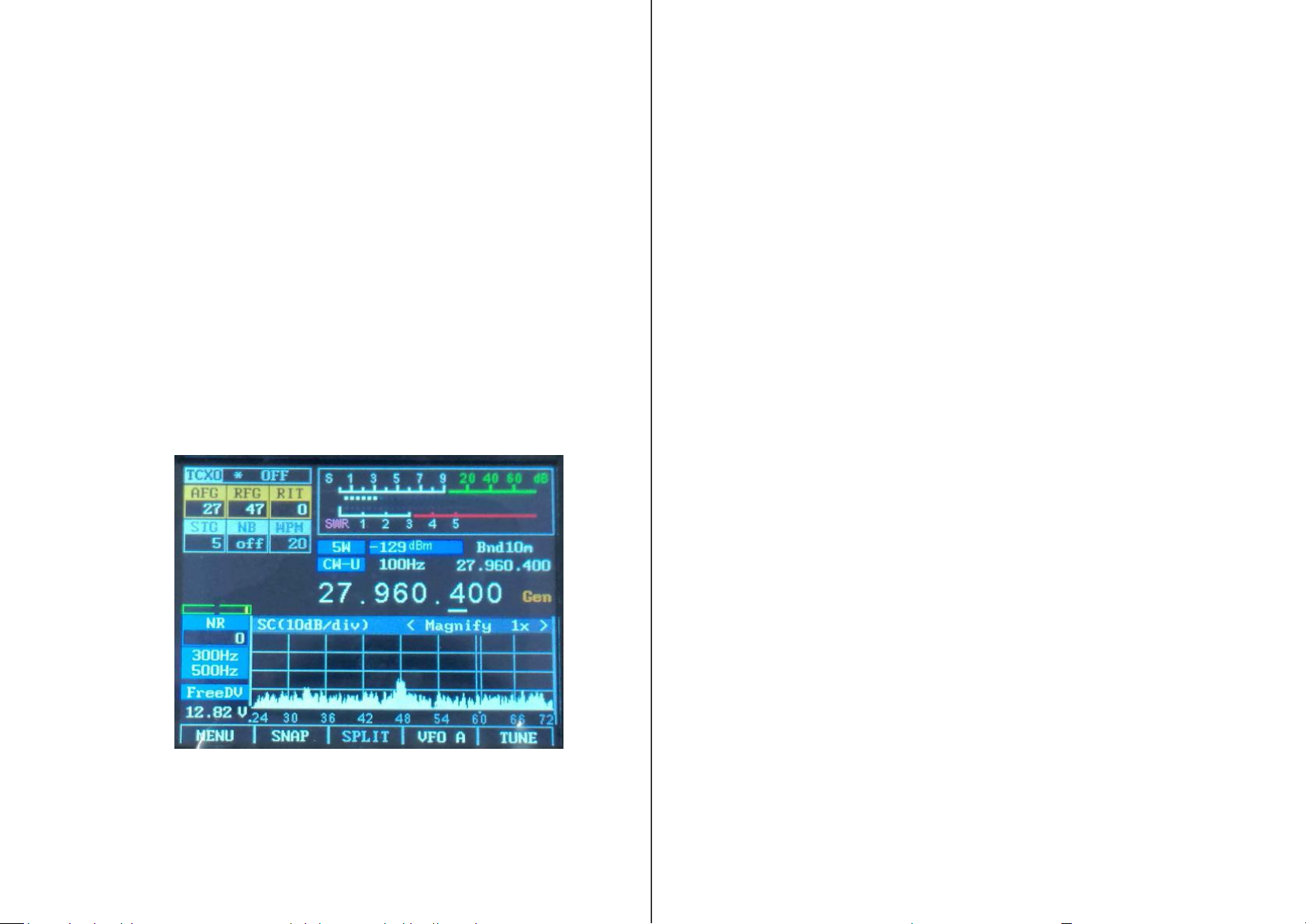
Figure 4 shows an alternate method of displaying signals near the
currently-tuned receiver signal is the Waterfall Display. In this
mode, the frequency is displayed along the “X” (horizontal)
axis,just as in the case of the Spectrum Scope but instead of the
signal strength being displayed as height, it is displayed as relative
“brightness”. The waterfall displayed is so-called because it can
convey the history of recent signal in time by showing the most
recent signals at the bottom,but when new signals are analyzed,
the older signals are displaced vertically and the newest signals
are placed along the bottom. In this way, one has a quick visual
“history” of what has occurred not only on the center frequency.
Figure 4: A typical waterfall display in the "Magnify" mode
showing +/- 12 kHz (24 kHz) of a band segment. When "magnify"
mode is NOT active +/-24 kHz (48 kHz) of a band is visible.
Options available to both the Spectrum Scope and Waterfall
Display:
• An adjustable “smoothing” filter (menu item “Scope/Wfall
Filter”) is available that dramatically improves the visibility of
rapidly-changing signals In the menu system, the range of the
Spectrum Scope may be set to span either +/- 24 kHz or +/- 12
kHz, with the scope's AGC operating only on signals within the
displayed span – see the menu setting “Spec. 2x magnify” for
more information.
• Also available are “Window function” selections that operate on
the input FFT data to both the Spectrum Scope and the Waterfall
Display that pre-process the spectral data to minimize “spill-over”
of adjacent FFT “bins”. What this can do is make the Spectrum
Scope and Waterfall display look “sharper” and prevent a strong
signal from “leaking” over and covering a weak one.
Connectors:
On the right-hand side of the transceiver on the UI board are four
3.5mm three-conductor connectors. Starting from the top, these
connectors are:
• Line Out (J1). This is a receive audio output that is fixed
level (unaffected by the volume control) that may be used to
supply audio to a computer for “sound card” (digital) modes.
This connector also carries the audio being transmitted.
• Line In (J2). This input may come from a computer for
“sound card” (digital) for transmitting. Its use must be
selected in the menu for it to be used.
Page 9

Ailunce HS1 User’s Manual
9
• Microphone/PTT (J3). This connector has both a
microphone connector with bias voltage (if R68 is installed)
for powering an electret microphone and a PTT
(Push-to-Talk) line that is shorted to ground to key the radio.
While the PTT line is always active, the microphone must
be selected as the active audio input from the menu for it to
be used. (Note that this is also the “Dah” line, which is also
used for keying in CW “straight key” mode.)
• Speaker/Phones (J4). This jack feeds and external
speaker/headphones, disconnecting the internal speaker when
something is plugged into it.
• Warning: There is no limiting resistor in series with
this audio connection, so you must remember to turn
down the volume before plugging in headphones.
On the RF board, along the right side, there are three connectors.
Starting from the top these connectors are:
• Power connector (J1). This is a coaxial power connector,
5.5mm O.D., 2.1mm I.D., that supplies power to the
transceiver. The outer shell is negative and the inner
conductor is positive.
• Paddle (J2). This connects to either a set of Morse paddles
or a straight key. The outer conductor (“ring”) is typically the
“Dah” while the tip is the “Dit” when in Iambic mode. In
“Straight Key” mode only the outer conductor (“ring”) is
used. (The “Dah” line is the same as the “PTT” line.)
• Accessory (J3). This is used for interfacing with an
external device and may be used for keying the transmitter
and/or determining when the transmitter is keyed. The “tip”
of this jack is the “PTT”/”Dah” line and may be used when
interfacing the transceiver to a computer when operating a
digital mode. The outer conductor (“ring”) is grounded
when the transceiver is in transmit mode and this may be
used to key an external amplifier or TR switch.
• The upper, “A” type (full-sized) USB connector is a USB
host port that may have future use for storage of data/audio
files and/or interface devices such as keyboards and wireless
devices. It is also possible to load firmware from a USB
memory stick from the interface.
• The lower “mini” USB host port is primarily used for
programming firmware into the transceiver.
On the left-hand side of the UI board are two USB connectors.
Finally, the sole connector on the left-hand side of the RF board is
the BNC-type antenna connector, the nominal impedance being 50
ohms.
Page 10

Ailunce HS1 User’s Manual
10
Operational modes and functions:
After powering up, the HS1 transceiver will revert to receive
mode on the last frequency, in the mode and using the audio
bandpass filter that was in use when it was last powered down
using the POWER button. In this mode LD1, the left-hand LED
(typically green) is illuminated.
By default, ENC1 controls the volume, ENC2 the RF Gain and
ENC3 controls the RIT.
When in transmit mode LD2 (typically red) the right-hand LED is
illuminated. In transmit mode most of the controls are frozen, this
being done to prevent the change of frequency, filter type and
mode during mid-transmission.
Tune mode may be entered by pressing the button located below
the TUNE icon on the screen (e.g.button F5) at any time and in
this mode a carrier is generated, along with an audible sidetone in
the speaker, the amplitude being set by the “Sidetone Gain” (STG)
setting. The output power may adjusted during transmit by
pressing the button PA to cycle through the settings. The TUNE
label on the LCD will turn red while TUNE mode is active.
Pressing the TUNE button again will exit.
Receive mode:
Transmit mode:
TUNE mode:
Always have a suitable load connected to the transmitter
(matched antenna or dummy load) before entering TUNE mode
or ANY transmit mode.
Notes:
When not in Menu mode, “soft” button F4, beneath the display. This button
toggles which VFO, A or B, is currently the “Active” VFO. This display
will change, always indicating the currently-active VFO.
If SPLIT mode is not active, the currently active VFO's frequency, filter
selection and mode are used for both receive and transmit.
If SPLIT mode is active the currently active VFO's frequency and filter are
used for receive while the “other” VFO's frequency is that used for
• When in TUNE mode audio being input to the Microphone and
LINE inputs will be ignored.
• When TUNE is activated in SSB mode, the frequency offset from
the display frequency and the sidetone frequency (e.g. the tone
emitted from the speaker) will always be 750 Hz.
• Note: There will be no tone in SSB-TUNE mode when frequency
translation is active.
• When TUNE is activated in CW mode the frequency offset from the
display frequency and the sidetone frequency will be that configured
as the sidetone frequency in the menu.
• Pressing-and-holding the TUNE button will toggle the Transmit
Disable function. If this is activated the TUNE indicator above button
F5 will be displayed in grey and pressing it will have no effect. The
“Transmit Disable” function may also be enabled/disabled in the
configuration menu.
VFO A (or VFO B):
Page 11

Ailunce HS1 User’s Manual
11
transmit: The transmit mode is always that of the “active” (receive) VFO.
The SPLIT mode will be discussed in more detail below.
If one PRESSES AND HOLDS this button (F4) the currently active VFO's
mode, filter setting and frequency are copied to the inactive VFO with an
on-screen indication that this has taken place.
When not in Menu mode, “soft” button F3 toggles “SPLIT” mode
on and off.
When SPLIT mode is off the radio behaves normally, using the
currently selected VFO for both receive and transmit.
When SPLIT mode is on, the radio uses the currently-selected
VFO's mode for both receive and transmit, the current VFO's filter
and frequency for receive and the “other” VFO's frequency for
transmit. In this mode, the main frequency display is also changed,
showing both the receive and transmit frequency, separately.
To set up for SPLIT mode one might do the following:
• Activate the SPLIT function. “SPLIT” has now changed color and the
display shows two frequencies.
• Suppose that a DX station is transmitting on 14.155 and
receiving on 14.165, USB. In that case, you would transmit on 14.165
and receive on 14.155.
• Dial in your transmit frequency of 14.165 MHz – the receive
frequency of the DX station.
• Press the VFO A/B button to move that frequency to the “other”
VFO: That is now your transmit frequency.
• Dial in your receive frequency of 14.155 – the transmit frequency
of the DX station – and also set USB mode and your desired filter
bandwidth.
• You are now ready to go! - It doesn't matter which frequency is in
VFO A or B.
• When installing and then using this firmware for the first time
there may be a problem with saving the VFO A/B frequencies. After
using the POWER button to save the settings once or twice it
appears as though the memory locations get properly initialized and
that they work as they should thereafter.
• The SPLIT mode works only on the same band – this to prevent the
destructive battering of the band-switch relays that might occur with
crossband operation – which would also slow down transmit/receive
switching.
• When using FM mode it is possible to use the SPLIT function for
repeater operation if one VFO contains the repeater input frequency
and the other contains the repeater output frequency. By “swapping”
the VFOs one may also do a “reverse” function and listen to signals
on the repeater's input frequency.
Important Comments related to SPLIT mode and VFO A/B:
◎Note that it is possible for one to set the STEP to 100 kHz
and using the main knob to tune the receive frequency to
another band and operate split that way, but this is not
recommended and you do this at your own risk!
SPLIT:
Page 12

Ailunce HS1 User’s Manual
12
In “normal” operation the spectrum display will be visible on the
screen and the five “Function” buttons along the bottom of the
display will have the following functions:
“Soft” buttons in normal operation:
• MENU (button F1) – This enters the menu system, allowing the
configuration of the transceiver. Pressing and holding this button will
save all settings to EEPROM.
• METER (button F2) – This button selects the mode of bar graph
below the S-meter which is used to display different parameters while
transmitting. Repeatedly pressing this button selects, in turn, the display
of SWR, AUD and ALC.
• SPLIT (button F3) – This button toggles “SPLIT” mode on/off. When
on (“SPLIT” is yellow), the transmit and receive frequencies are
separated using VFO A and B as shown on the main frequency display.
• VFO A or VFO B (button F4) – This button toggles whether VFO A
or VFO B is the “primary” VFO. The VFO that is being displayed is
ALWAYS the one being used for receive.
• TUNE (button F5) – This button toggles the TUNE mode on/off.
Pressing and holding this button will disable transmit as indicated by
this indicator being displayed in gray.
Pressing the MENU button (e.g. button F1) will enter the main menu system
by which many parameters of the transceiver may be configured: These
parameters will be discussed in detail later. Pressing-and-holding this button
will save all settings to EEPROM.
Upon entering the MENU mode several of the “soft” buttons along the
bottom of the screen willchange their function:
“Soft” buttons in MENU mode:
• EXIT (button F1) – This exits the menu system, returning to the
main display. Pressing-andholding this button will save all settings to
EEPROM.
• DEFLT (button F2) – This button resets the currently-selected item
to its default setting.
• PREV (button F3) – This button goes backwards one screen or six
menu items. Pressing-andholding this button will jump to the
beginning of the menu, or to the end of the menu if already at the
beginning.
• NEXT (button F4) – This button goes forwards one screen or six
menu items. Pressing-andholding this button will jump to the end of
the menu, or to the beginning of the menu if already at the end.
• The TUNE mode remains present while in the MENU system at
button F5
Note: If an item has been changed in the menu system that may
need to be saved to EEPROM using the POWER button, the
MENU indicator will be orange and be followed by an asterisk
(e.g. “MENU*”)
Configurable options on the main screen:
In the upper left corner there are a number of items on the main
screen that are configurable using the buttons and/or encoders
• AFG - “AF Gain” (a.k.a. “Volume Control”). This is used to adjust
the audio level feeding the speaker/headphone jack using encoder
ENC1. Button M1 may be used to select whether this encoder adjusts
AFG or STG (see below) with the “un-selected” item being “grayed”
out. AFG (e.g. the “Volume control) is always enabled when in Menu
mode.
• STG - “Sidetone Gain” while in CW mode. This is used to adjust the
Page 13

Ailunce HS1 User’s Manual
13
level of the sidetone that is heard during keying while in CW mode
and while in TUNE mode using encoder ENC1. Button M1 may be
used to select whether this encoder adjusts STG or AFG with the
“unselected” item being “grayed” out. Sidetone Gain is also
adjustable from the main menu. When not in CW mode this is
replaced with “CMP”.
• CMP - “TX Compression Level” while not in CW mode. This is
used to adjust the amount of audio compression when in voice mode.
When in CW mode this is replaced with “STG”.
• RFG - “RF Gain”. This control, as the setting is decreased, causes
an increased deflection in the S-Meter and a commensurate decrease
in the receiver sensitivity. This functions in exactly the same way as
the “RF Gain” control on a traditional analog receiver and is typically
used to limit the receiver sensitivity on a noisy band. Button M2 may
be used to select whether this encoder adjusts RFG or NB (see below)
with the “un-selected” item being “grayed” out. This
parameter may also be adjusted from the main menu.
• DSP – This adjust the “strength” of the DSP noise reduction, when
enabled. Pressing-andholding button M2 will select between this
parameter or “NB” (Noise Blanker adjust) being visible. Turning the
DSP on and off will also reset the DSP noise reduction/notch engine.
• NB - “Noise Blanker”. This control adjusts the “strength” of the
noise blanker, with “0” being “disabled.” This is a “pulse” type noise
blanker operating on the wideband input prior to filtering in the DSP
input. As the noise blanker strength is increased, the color of the
number changes to warn the user that the higher numbers are more
likely to cause degradation of the receive audio. Button M2 may be
used to select whether this encoder adjusts NB or RFG with the
“un-selected” item being “grayed” out. Pressing-and-holding button
M2 will select between this parameter or “DSP” being visible.
• RIT - “Receive Incremental Tuning”. This offsets the receiver, in 20
Hz steps, to allow the transmit frequency to be different from that of
the receiver with the actual receive frequency being shown on the
“sub” frequency display above and to the right of the main frequency
display. Button M3 may be used to select whether this encoder adjusts
RIT or WPM (see below) with the “un-selected” item being “grayed”
out.
• WPM - “Words Per Minute” while in CW mode. This adjusts the
Morse sending rate in “Words Per Minute” when using Iambic mode
keying. Button M3 may be used to select whether this encoder adjusts
WPM or RIT (see below) with the “un-selected” item being
“grayed” out. The Morse WPM setting may is also adjustable from
the main menu. When not in CW mode this is replaced with “MIC”
or “LIN”.
• MIC or LIN - “Microphone Gain” or “Line Input Gain” when not
in CW mode. This adjusts the Microphone (or Line Input) gain,
depending on which is enabled. When in CW mode this is replaced
with “WPM”. Pressing-and-holding button M3 will select
Microphone or Line-Input modes. Note that if this is changed during
transmitting, one must briefly unkey for the change of inputs to take
effect.
Automatic switching of on-screen items when going from
receive to transmit:
Using the item in the “Configuration Menu” labeled “O/S Menu
SW on TX” and setting it to ON several of the on-screen items
will change automatically when going from receive to transmit and
back again when returning to receive when in SSB mode: This
function is NOT available in CW mode.
Page 14

Ailunce HS1 User’s Manual
14
These parameters include:
▪ This automatic switching facilitates the adjustment of the relevant
parameters when in transmit mode without having to pause and press the
M1 and/or M3 buttons to switch the functions of the relevant knobs.
▪ Note that if you already had selected an alternate function while in receive
(e.g. “CMP”) it will “remember” and return to that setting after you have
been in transmit and again turned to receive.
▪ Setting the parameter “ O/S Menu SW on TX” to OFF prevents the above
parameters from changing when going between receive and transmit.
Button G2 is used to enable/disable the DSP function, providing the
following settings:
Pressing-and-holding button G2 will “save” the currently-selected DSP
mode, if on, and turn it off. Pressing-and-holding this button again will
restore the mode(s) that had been configured when it had been turned off.
The “strength” of this filter may be adjusted using the menu item #10, “DSP
NR Strength” - but be very careful with this as it easy to go overboard with
this setting. If it is set too high, the artifacts caused by the noise reduction
(e.g. “hollow” or “watery” sound) can be worse than the interference
thank you are trying to remove!
• CMP (in voice mode)
• MIC or LIN (in voice mode)
DSP (Digital Signal Processing) Noise Reduction and
Automatic Notch Filter:
• OFF – DSP Functions are turned off
• NR – Noise Reduction only
• NOTCH – Automatic Notch Filter only
• NR+NOT – Noise Reduction and Notch Filter
The “strength” may also be set using button M2 and ENC2 without having
to enter the menu system. To do this:
IMPORTANT OPERATIONAL NOTES related to DSP and
the noise blanker:
• Enable DSP “NR” mode by pressing button G2.
• Press button M2 so that the highlighting changes from RFG to
DSP on the screen.
• If “NB” is displayed instead, press-and-hold button M2 to
change it.
• With DSP highlighted, ENC2 will now allow adjustment of the
DSP noise reduction “strength”.
• You will note that the number denoting DSP “strength” is greyed
out when DSP is turned off and cannot be (accidentally!) adjusted.
• All DSP functions are disabled until a few seconds after the radio
boots up.
• The notch filter is automatically turned off in CW mode. It cannot
be selected when in CW mode. The reason for this is that the notch
filter would “kill” CW signals!
• ALWAYS turn all DSP modes off when you are using any “sound
card” (digital) modes such as PSK31, RTTY, SSTV, etc. DSP is
NOT compatible with these modes!
• The noise blanker is always disabled in the wide bandwidth (5, 6,
7.5 or 10 kHz) mode.
• The noise blanker is disabled in AM mode.
• Enabling the noise blanker and DSP can cause the user interface of
the HS1 to slow down significantly! What this means is that the
response to button-presses and the updates of the
spectrum scope can be significantly slower. (You have been warned!)
Page 15
Ailunce HS1 User’s Manual
15
There are additional “advanced” configuration settings related to the DSP
modes available: See the items in the menu system and the section on
“Advanced DSP Setting.
Warning:
• The DSP Noise Reduction and the Automatic Notch Filter
(“Notch”) are separate functions that operate independently. Because
of this, operating on “NR+NOT” mode takes more processor
“horsepower” than either “NR” or “NOTCH” alone.
• The noise blanker takes about as much processor power as both the
DSP NR and “Notch” put together which is why turning on the noise
blanker in addition to DSP can significantly slow down the
transceiver's response – and also why the noise blanker is disabled in
AM mode and when set to a wide bandwidth mode – either of which
take more processor power in their own right!
• When DSP NR is active, the parameter “DSP NR FFT NumTaps”
can significantly change processor loading: The higher this value, the
more loading. If you need to have DSP turned on, but you find the
user interface to be operating too slowly, try setting this to a lower
value: This can decrease the “quality” of the noise reduction
somewhat, but it will free some processor power.
Tips to minimize processor loading when using DSP:
It is possible to select the combination of wide bandwidth, DSP noise
reduction and DSP Notch (e.g. “NR+NOT”) while in AM mode. This
combination can “stall” the radio with too much processor power,
making operation sluggish and result in distorted audio. If you do
this, you may press-and-hold the DSP button to disable DSP and
“un-select” some of these options.
Using the HS1 Transceiver – Brief Overview
Figure 5: Front panel controls of the HS1 transceiver
Note:
If you are unfamiliar with the HS1, please refer to the section
of the manual: “Before you get on the air - Initial set-up of
the HS1 transceiver”
To turn on the transceiver, press the POWER button briefly and
the display should light up, go through its attribution and boot-up
screen and display the frequency and spectrum display.
Receive:
• Adjust volume using the ENC1 control.
• Tune the frequency using FREQ ENC knob. Select the step
size using the STEP- and STEP+ buttons.
• Pressing-and-holding the STEP- or STEP+ button will
temporarily decrease/increase the step size while tuning, the step
size display changing colour while this is in effect.
• Pressing-and-holding both the STEP- and STEP+ buttons at the
same time will enable/disable the “Frequency Lock” mode. The
Page 16

Ailunce HS1 User’s Manual
16
main frequency display will turn grey when “Frequency Lock” is
enabled. The RIT is still enabled when the frequency is locked.
• Change the band using the BND- and BND+ buttons.
• Change the mode (USB, LSB, CW, etc.) using button G1. Note:
Pressing-and-holding this button will force the selection of
“disabled” modes.
• Button G4 selects the receiver bandwidth.
Note: Pressing-and-holding this button will force the selection of
“disabled” bandwidths.
• Pressing button G2 will select the mode of DSP noise reduction.
• If RIT is desired, use ENC3 to shift the receive frequency: The
small frequency display will show actual receive frequency
display when RIT is set to non-zero, but the large display will
show the transmit frequency.
• Pressing and holding button G2 will turn DSP off,
saving the current settings while pressing and holding
again will restore the last-used mode. The available DSP
modes are:
There are certain configurations where some/all of the DSP
functions are not available. For example, the notch filter is
disabled in CW mode (for obvious reasons!) and DSP is
completely disabled in FM mode.
• NR = Noise reduction only
• NOTCH = Automatic notch (tone) filter only
• NR+NOT = Both Noise reduction and Automatic
notch filter.
Transmit:
Initial SSB transmit audio set-up:
Set the receive frequency and mode, setting the desired output
power using button G3. Note that it is recommended that for
voice modes that “full” power not be used unless you have
carefully configured for clean, linear output power.
• Preferably, connect the HS1 transceiver to a 50 ohm dummy load
capable of handling at least 10 watts. Alternatively, you may tune to a
clear frequency while connected to an antenna with a known-good 50
ohm match.
• Use button G1 to select LSB or USB mode as desired.
• Press button F2 to select the AUD io meter.
• For testing, press button G3 to select the 0.5 watt setting: The power
setting does not matter for this configuration.
• Connect the microphone to connector J3: This is is the one just
above the speaker connector on the right side of the UI board, below
and to the right of the FREQ ENC control. The HS1 is typically used
with an electret-type microphone element and power for the
microphone element is supplied by the radio.
• Press button M3 to switch from RIT to MIC. If the box to the
right-hand side of RIT shows “LIN” which indicates that line-input
mode is active, press-and-hold button M3 to change it to MIC. Press
button M3 as necessary to highlight MIC on the display: This allows
the adjustment of the microphone gain.
• Now, key the radio using the Push-to-Talk (PTT) button on the
microphone: The spectrum display should freeze.
• Speak normally into the microphone. You should see the indicator
on the AUDio meter bounce upwards. While speaking, adjust the
ENC3, which adjust the MIC parameter, so that the AUDio meter
Page 17

Ailunce HS1 User’s Manual
17
indication peaks up to +4 or so (in the red) on peaks. Occasional,
higher, higher peaks are permissible, but avoid settings that cause
full-scale indications which could imply distortion.
• Release the PTT button and press button F2 to select the ALC
meter.
• Press button M1 to highlight the CMP on the display: This will
allow the adjustment of the compression level of the speech
processor.
• Press the PTT button and speak normally again. You should see
the ALC meter indicate upwards on voice peaks occasionally: If it
does not, increase the MICrophone gain slightly.
• Adjusting CMP to a higher value will increase the
aggressiveness of the speech processor: A value of 2 is a nice,
modest value and a value of 12, while very “punchy” and can be
used to maximize “talk power” will sound very “processed” and is
likely to be unpleasant for normal, casual QSOs. The value of
“SV” will select custom settings – see the menu for additional
information.
• Once you have configured the settings to your satisfaction,
press-and-hold button F1 to store them in memory.
What to do if you notice that the ALC or AUDio meters jump
when you key your microphone:
• In a quiet room with an antenna or dummy load connected to the HS1, set
the METER mode to ALC and key the microphone/transmitter without
talking and note if ALC meter jumps at the instant that you key the
transmitter and goes down again. Next, switch the METER mode to AUD
and key the microphone/transmitter again, watching the AUDio meter.
▪ If you notice that either meter jumps upwards when you key the
transmitter and drops down again your keying the transmitter may be
electronic “click” or mechanical “clunk”, “de-sensing” the transmitter's
ALC. This can be caused by the the powering-up of the electret element in
the microphone when the radio is keyed and/or by the (noisy!) mechanical
action of the switch – but the result can be the same in either case: A
temporary “desense” when you start talking and/or an annoying sound heard
by the station receiving you!
• To minimize this adjust menu item “TX Mute Delay” which will keep the
microphone audio muted for a short period after keying up. The parameters
are adjustable from 0 (off) to 25, which keeps the audio muted for a full 250
milliseconds (one-quarter of a second) after the microphone is keyed.
▪ It is recommended that one finds the minimum value to reliably suppress
the appearance of the microphone key-up noise and then increase it by 50%.
◎ AM transmission operates the same way as SSB, but frequency
translation mode must be activated. Remember also that the
unmodulated carrier in AM will be ¼ that of the PEP power in SSB!
Important information regarding the “Frequency Translate”
mode:
• Menu item “RX/TX Freq Xlate” selects the enabling/disabling of
baseband frequency translation in the receiver/transmitter. When the
translation is active, instead of the receiver operating at and around "DC",
the signals are mathematically shifted from 6 kHz (above or below –
user-selectable). Whether or not frequency translate mode is enabled is
displayed on the start-up splash screen.
• Performing this frequency shift can help forgive a lot of the "sins" that
occur with "DC" conversions - the most obvious of which are that ANY
noises in the power supply as well as the 1/F noises of op amps, mixers,
Comments when using AM:
Page 18

Ailunce HS1 User’s Manual
18
A/D converters and the like tend to show right up in the received audio.
With the signals at microvolt levels, it is a real fight to minimize these
signals! These signals/problems can show up as:
It should be noted that these code modifications DO NOT relieve the
builder of the strong recommendation that one perform the modifications
in the "HS1 Board Modifications" file, particularly the U3a and MCU and
LCD power supply modifications (for UI board 0.3) but they should go a
long way toward reducing the artifacts that can still occur even after making
those modifications - even to the point of gaining an extra S-unit or two in
sensitivity.
Menu item “RX/TX Freq Xlate” has the following options:
• Hum
• Howling
• Audio feedback, particularly at higher volumes
• Buzzing with the dimming of the backlight
• Noises from the I2C communications (e.g. “ticking”)
• OFF - This is the original operation of the transceiver with the
receive (and transmit) signals operating at and around zero Hz.
• RX LO HIGH - In this mode the signals are shifted BELOW zero
Hz by 6 kHz, requiring that the local oscillator be shifted up by the
same amount. The received signals are tuned at the first graticule left
of center on the spectrum scope.
• RX LO LOW - In this mode the signals are shifted ABOVE zero
Hz by 6 kHz, requiring that the local oscillator be shifted down by the
same amount. The received signals are tuned at the first graticule right
of center on the spectrum scope.
For various reasons (e.g. the use of USB on higher bands where the
potential for zero-HZ interference is highest) the use of “RX LO LOW”
is recommended for best performance!
Quirks and side-effects:
When the translate mode is activated and “magnify” mode is not turned on
you will note that the receive signal is no longer in the center of the
spectrum scope! Along the bottom of the spectrum scope you'll observe
that the frequency display is changed, with the frequency in kHz being
displayed in full under the graticule, being shifted left or right as noted
above.
If you have used other SDR software – particularly “sound card” SDR
rigs on computers – you will already be familiar with this sort of shift!
Using the HS1 with computer “Sound Card” (e.g. digital) modes via the
Line-Input and Line-Output connections:
The HS1 may be connected to a computer, tablet or smart phone via audio
cables and the PTT line on the Microphone cable to allow modes such as
SSTV, PSK31, WSPR or other digital “Sound Card” mode. To do this,
configure the transceiver as follows:
• Using button G1, select USB mode: All digital modes are operated
using USB, regardless of band. In this way the audio frequency of the
digital signal may be added to the frequency display to calculate the
actual transmit/receive frequency.
• Set RIT to zero using ENC3: Press button M3 as necessary to
highlight RIT to allow adjustment. When using a digital mode the RIT
MUST be disabled or else you will have difficulty making contacts!
• Set CMP to zero using ENC1: Press button M1 as necessary to
highlight CMP to allow adjustment. When using a digital mode, the
audio compressor must be set to MINIMUM (0) or else it may
degrade the digital signal!
• Before connecting the external device (Computer, tablet, phone) set
Page 19

Ailunce HS1 User’s Manual
19
the audio output level to mid-scale. Also set the audio input gain to
approximately mid-scale as well.
• For receive, one may use any of the available receive audio filters,
but it is recommended that the Wide filter not be used! If narrow
(300Hz, 500Hz or 1.8 kHz) filters are used, one may shift the center
frequency of that filter in the menu to suit the passband for that
mode, but be aware that it is possible to run too narrow a filter for
some of the “wider” digital modes! In the vast majority of cases the
2.3kHz filter will be adequate.
• Be certain that DSP filtering is turned off! The DSP noise
reduction or notching on any radio necessarily alters signals and
doing so can degrade them, making them difficult for the attached
computer/device to decode!
Connect the Line-Input jack (J2) of the HS1 to the audio output of the device
you are using to generate the audio and connect the Line-Output jack (J1) of
the HS1 to the audio input of that same device.
To key the transceiver, you will need also to connect a cable the Microphone
jack (J3 on the UI board) or the Key jack (J2 on the RF board) and the
PTT/Key line on either of those jacks (the “ring”) would be grounded to key
the transceiver: Typical rig-computer interfaces will easily accommodate this
connection.
• Preferably, connect the HS1 transceiver to a 50 ohm dummy load
capable of handling at least 10 watts. Alternatively, you may tune to
a clear frequency while connected to an antenna with a known-good
50 ohm match.
• Using button M3, select LIN mode. You may need to
press-and-hold this button to change from MIC to LIN. Press
button M3 as necessary to highlight LIN.
• Using button F2 select the AUDio meter.
• Using button G3 set the HS1 to 0.5 watts for this setup.
• Using the program running on the external device, key the computer
using the selected mode. If the program has a “test” mode, use it for
this.
• Adjust the LIN setting via ENC3 for a reading on the AUDio meter
of +2 to +4.
• Make sure that you have set “CMP” to 0 as noted above!
• Un-key the transceiver.
• Make a note of the settings that you have used for future reference.
• Find a signal on the bands representative of the mode and adjust the
audio input level of the external device for approximately
“mid-scale”. The Line Output level on the HS1 on this version of
firmware is fixed.
• It should be noted the the LINE OUT jack will contain the transmit
audio. This is an artifact of the hardware configuration.
• Once you have configured the settings to your satisfaction,
press-and-hold button F1 to store them in memory
TUNE mode:
The operation of the TUNE mode is very simple:
The TUNE button may be used to send an unmodulated (CW) carrier for
brief testing, such as checking the RF power output or the VSWR/matching.
The TUNE function is also used for initial adjustment of various parameters
(TX Gain, Phase) as described elsewhere in detail.
• Press the TUNE button: The HS1 transmits and the indicator turns
red.
• Press the TUNE button again: The HS1 stops transmitting and the
indicator turns white.
Comments about the TUNE mode:
Page 20

Ailunce HS1 User’s Manual
20
• When set to CW mode, when TUNE is activated the HS1 will
produce a carrier above the dial frequency by the amount of the setting
of the “CW Side/Off Freq” (e.g. sidetone frequency).
• When set to SSB mode, when TUNE is activated the HS1 will
produce a carrier that is offset from the dial frequency by 750 Hz – the
same as the audible sidetone. This carrier will be below the dial
frequency in LSB mode and above it in USB mode.
• Pressing-and-holding the TUNE button will toggle the TRANSMIT
DISABLE function. If this mode is on, the TUNE indicator will turn
gray and all transmit capabilities of the HS1 will be disabled. This is the
same as the parameter “Transmit Disable” in the configuration
menu.
• TUNE mode does not function in AM mode.
• Note: There will be no audible sidetone in “SSB TUNE” mode
when Frequency Translation is enabled.
Configuration of the HS1 for CW operation:
• Connect a key or paddle to jack J2 on the RF board: This is the
connector next to the DC power input.
For connecting a paddle for Iambic keying:
• The TIP of the connector is DIT.
• The RING of the connector is DAH.
Note: The “dit” and “dah” may be swapped using the “CW Paddle
Reverse” menu setting.
For connecting a straight key, mechanical semi-automatic key (e.g. a
“bug”) or an external
• The RING of the connector keys the transmitter.
Note that the DAH/Straight Key connection is the same as the “PTT”
line on the Microphone connector.
Now, press the MENU button (F1) and use the NEXT and PREV buttons
(F4 and F3, respectively) to navigate to the screen containing the menu item
“CW Keyer Mode”, noting the setting to the right of it. The three possible
settings are:
• IAM_A – Iambic mode “A”. Using paddles, alternate dots and dashes
are sent with both paddles are depressed, stopping with the last dot or
dash that was sent while the appropriate paddle was depressed.
• IAM_B – Iambic mode “B”. The same as mode “A” except that
keying continues by sending one more element – a dot if the paddles
were released during a dash and vice-versa.
• STR_K – Straight Key. This would be used for a straight key, a
“bug”or external keyer/computer.
• CW Paddle Reverse – This reverses the DIT and DAH positions of
the paddle, affecting ONLY the IAMBIC modes when using the built-in
keyer.
• CW TX->RX Delay – This sets the delay, after the last CW element,
before the transceiver returns to receive mode.
• CW Side/Off Freq – This sets the offset frequency and sidetone in
CW operation, adjustable in 10 Hz steps.
Additional items on this menu (you may need to scroll to another screen
using ENC2) include:
◎ Note: If the sidetone frequency is adjusted, the center
frequencies of the 300 Hz and 500 Hz filters should be adjusted
to compensate to keep the frequencies within the center of the
filter passband!
Page 21

Ailunce HS1 User’s Manual
21
• The parameters CW Keyer Speed and CW Sidetone Gain are
adjustable from the main display and will be discussed shortly.
• CW Freq. Offset – This sets the display/shift mode to be used for
CW operation: For more details on this parameter, see the MENU
section.
• Press button G1 to select the CW mode.
• Press button G4 to select the desired receive audio bandwidth.
• Press button G3 to set the power to 0.5 watts: The power has little
effect on this adjustment.
• Press button M3 to highlight the WPM parameter: Use ENC3 to set
the desired sending speed in words-per-minute. This parameter has
no effect if set to straight-key mode.
• Press button M1 to highlight the STG parameter: ENC1 is used to
adjust this parameter.
• Press the paddle/key to cause the HS1 to transmit: Use ENC1 to
adjust the volume of the sidetone. Note that the volume control
(“AFG”) setting has no effect on the level of the sidetone.
• Once you have configured the settings to your satisfaction,
press-and-hold button F1 to store them in memory.
• The DSP “NR” (Noise Reduction) mode may be used to advantage
when in CW mode, but note that the DSP “NOTCH” mode is always
disabled because it would “kill” CW signals!
• The sidetone frequency is exactly that of the amount of transmit
offset from the dial frequency.
• If the parameter “CW Side/Off Freq” is changed - which changes
the sidetone/offset frequency - remember to change the the center
To configure for CW operation:
Miscellaneous notes and tips:
frequencies of the 300 Hz and 500 Hz filters so that the center of your
receive filter passband will match your transmit frequency. If you do not
do this a station that returns to you on your frequency may do so outside
the passband of your receive filter!
• There is a slight interaction between the power setting, the perceived
loudness of the sidetone gain and the sidetone gain setting. This is a
known issue, but it has not been a cause of complaints.
• NOTE: Refer to the menu item “CW TX/RX Offset“ to set up the
transceiver for USB, LSB or “Automatic” USB/LSB operation as
desired. You may also configure the transceiver so that the frequency
displayed is that of the transmit carrier frequency or that of the received
signal when its pitched is matched to that of the transceiver's sidetone.
• Pressing-and-holding button G3 when in CW, LSB or USB mode will
generate a tone that is equal in frequency to the CW sidetone and
transmit-receive offset. This may be used to “spot” the frequency so that
you can transmit on the same frequency as the station with which you
are communicating. The loudness of this tone may be adjusted using the
“Adjustment Menu” option “Beep Volume”.
It is recommended that one NOT operate CW when the menu is
being displayed!
If the menu is being displayed, CW element timing will be
disrupted!
The configuration menu system:
The configuration menu may be entered by pressing the MENU button (F1).
When in the menu system, it may be navigated using the following encoders
and buttons:
Page 22

Ailunce HS1 User’s Manual
22
• ENC2 – Selects the individual menu item.
• ENC3 – Adjusts the selected menu item
• Button F1 – Exits the menu system, returning to the main
transceiver display. Pressing-and-holding will save settings to
EEPROM.
• Button F2 – Resets the currently-selected item to its default
setting.
• Button F3 – Goes backwards in the menu system by 6 items (one
screen). Pressing-and-holding this button will jump to the beginning
of the menu, or to the end of the menu if already at the beginning.
• Button F4 – Goes forwards in the menu system by 6 items (one
screen). Pressing-and-holding this button will jump to the end of the
menu, or to the beginning of the menu if already at the end.
• Button F5 – Enters/Exits TUNE mode. Pressing-and-holding this
button will also toggle “Transmit Disable”. The “TUNE” indicator
will turn gray indicating that the transmitter is disabled.
• When in MENU mode ENC1 is always configured as AFG (e.g.
the volume control.)
• Whenever a menu item is changed the warning “Save settings
using POWER OFF!” will appear along the bottom of the screen to
warn you that any changes that you may have made will NOT be
saved unless you power down the transceiver using the POWER
button.
• If you have made any changes while in the MENU system, when
you exit the MENU system the label above button F1 will be
orange and display “MENU *” to warn you that you should power
down using the POWER button to save any changes that you might
have made.
Important Notes:
There are two separate menus within the menu configuration system:
• The MAIN menu. These are the more commonly-adjusted items with
the labels in YELLOW.
• The CONFIGURATION menu. These are less-frequently adjusted
items used for calibrating
The CONFIGURATION menu is hidden unless it is enabled by activating it
by setting the last item in the main menu to ON.
Note:
All menu items are numbered, but the numbers are omitted here to
simplify maintenance of this document as these numbers occasionally
change as features are added/modif
Main Menu configuration items:
Important Note:
If, when the a menu item is changed, it will be necessary to
turn off the transceiver using the POWER button to save the
changes to the EEPROM.
Alternatively, button F1 may be pressed-and-held to cause a
save of all settings to occur.
It is strongly recommended that one NOT attempt to
operate CW when the menu is being displayed! If the
menu is being displayed, the CW element timing will be
disrupted!
These items are listed in the order that they appear in the menu system.
DSP-related items:
• DSP NR Strength – This adjusts the aggressiveness of the DSP
Page 23

Ailunce HS1 User’s Manual
23
noise reduction, with 0 being “weak” and higher numbers
correlating to “stronger” DSP noise reduction effects. The relative
effects of this parameter are affected by the “advanced” parameters –
see the “DSP Related Items” section. This is the same as the “DSP”
parameter controlled by ENC2 on the main screen.
• 300Hz Center Freq. - This sets the center frequency of the 300 Hz
CW filter, the options being 500, 550, 600, 650, 700, 750, 800, 850
and 900 Hz. A final option is “Off” which eliminates this filter from
the selection when button G4 is pressed. The settings will be
displayed in white if this filter is currently selected.
• 500Hz Center Freq. - This sets the center frequency of the 500 Hz
CW filter, the options being 550, 650, 750, 850 and 950 Hz. A final
option is “Off” which eliminates this filter from the selection when
button G4 is pressed. The settings will be displayed in white if this
filter is currently selected.
• 1.8k Center Freq. - This sets the center frequency of the 1.8 kHz
“narrow” SSB filter, the options being 1125, 1275, 1427, 1575 and
1725 Hz. A final option is “Off” which eliminates this filter from
selection when button G4 is pressed. The settings will be displayed in
white if this filter is currently selected.
• 2.3k Center Freq. - This sets the center frequency of the 2.3 kHz
SSB filter, the options being 1262, 1412, 1562 and 1712 Hz. The
settings will be displayed in white if this filter is currently selected.
This filter cannot be disabled.
• 3.6k Filter. - This enables/disables the filter and when set to “Off”,
this filter will be eliminated from selection when button G4 is
pressed. The settings will be displayed in white if this filter is
currently selected.
Filter-related items:
• Wide Filter Select - This selects the “wide” filter – that is, the next
bandwidth above the 3.6kHz bandwidth with four bandwidth being
available: 10 kHz, 7.5 kHz, 6 kHz and 5 kHz. If one of the “AM” items
is selected (e.g. “5kHz AM”) then the selected bandwidth will be
available only in AM mode but if a “non-AM” item is selected (e.g.
“5kHz”) then this selection will be made available in SSB mode as
well.
• Wide Filt in CW mode – When ON, the “Wide” SSB filters (3.6
kHz and Wide) will be available for selection when in CW mode.
• CW Filt in SSB mode – When ON, the “Narrow” CW filters (300
Hz and 500 Hz) will be available for selection when in SSB mode.
• AM mode disable - When ON, the AM mode will be eliminated
from selection when the G1 button is pressed. Note that it will still be
available if one presses-and-holds button G1.
• LSB/USB Auto Select – This enables the automatic selection of LSB
or USB, depending on the current band. The available settings are:
When “LSB/USB Auto Select” is enabled, pressing button G1 will
skip the sideband that is not appropriate for the frequency of operation
(e.g. USB will not be selected below 10 MHz) but
pressing-and-holding this button when LSB is displayed will change
the mode to USB – and pressing-and-holding again will change it back
to LSB.
When “LSB/USB Auto Select” is enabled, in order to change to AM
• OFF – No automatic selection.
• ON – LSB is selected < 10 MHz, USB is selected >= 10 MHz
• USB 60M – LSB is selected < 10 MHz except for 60 meters
and USB is selected >= 10MHz. This setting has been provided
for those areas where USB is typically used on 60 meters (e.g.
the U.S.)
Page 24

Ailunce HS1 User’s Manual
24
you must select a mode other than LSB (or USB) – such as CW – and
then press-and-hold button G1: AM will then be selected.
• FM Mode Enable - When set to ON the FM mode is available with
normal presses of the G1 button. Note: Even when off, it may still be
accessed if button G1 is pressed-and-held in CW mode. If the AM
mode is also set as being disabled, you may have to press-and-hold
G1 again to get to FM.
• FM Sub Tone Gen – This selects the frequency of the subaudible
tone (in Hz) to be transmitted on FM: The setting of “off” (default)
disables the tone. The deviation of this tone is approximately +/-300
Hz in “Narrow” mode and +/-600 Hz in “Wide” mode.
• FM Sub Tone Det – This selects the frequency of the subaudible
tone (in Hz) to be decoded on FM: The setting of “off” (default)
disables the tone decoder so that only “carrier squelch” is used. When
this is active it is necessary that both the squelch be opened AND the
tone decoded in order for audio to be heard. The “FM” mode indicator
on the main display will be backgrounded in red when the selected
tone is being decoded.
• FM Tone Burst – This enables and selects the transmission of a
“tone burst” (a.k.a. “whistleup”) that might be used to activate some
repeaters. Two frequencies are available: 1750 Hz and 2135 Hz. The
tone burst is activated by pressing-and-holding button G4 while
transmitting.
• FM RX Bandwidth – This selects the detection bandwidth when in
FM mode: Selection of “audio bandwidth” via button G4 is disabled
as it is irrelevant in FM mode and this setting is unlikely to be
changed very often. The selections are:
FM mode-related items:
◎ 7.2 kHz – This is suitable only for “Narrow” operation and
even this will result in a bit of added distortion as the filter about as
narrow as it may be to pass audio. Using this setting the weak-signal
sensitivity is the highest amongst the FM filter bandwidth settings
since this narrowest filter also intercepts less noise under weak-signal
conditions.
◎ 10 kHz – This is the “default” bandwidth and is suitable for
“Narrow” bandwidth and while it will work for “Wide” bandwidth,
slight distortion may occur on voice peaks.
◎ 12 kHz – This is wider than necessary for “narrow” bandwidth and
recommended for “Wide” bandwidth.
◎ Operation of “Wide” (+/-5kHz) on “Narrow” frequencies will result
in “loud” audio, possible “squelch clamping” and splattering onto
adjacent “narrow-spaced” channels.
◎ Operation of “Narrow” (+/-2.5kHz) on “Wide” frequencies will
result in chronically “low” audio, reduced “copyability” under
weak-signal (noisy) conditions and everyone telling you to talk
louder!
• FM Deviation – Two “modes” of FM are available: “Narrow” with +/-
2.5 kHz peak deviation (w/1kHz modulation) and “”Wide” with +/- 5 kHz
peak deviation, the former being commonly used on HF and the latter
being that which is used on VHF bands except for those instances where
the “narrow” (+/- 2.5 kHz) mode is specifically used. These two modes
are more or less interoperable, with the following provisions:
Page 25

Ailunce HS1 User’s Manual
25
AGC and other receiver-related items:
• AGC Mode - The selections are SLOW, MEDium, FAST,
CUSTOM and MANUAL. These related to the “decay” speed (e.g.
“hang”) of the receive AGC. When in MANUAL mode the AGC is
disabled and the audio gain is set to maximum – see “RF Gain”,
below. WARNING:
Reduce volume level before setting this to MANUAL!
• RF Gain - This is the same as the “RFG” (RF Gain) control from the
main menu and in this context it is used in conjunction with the
MANUAL AGC mode.
• Cust AGC (+=Slower) - When AGC Mode is set to CUSTOM this
sets the decay rate with a higher setting setting a slower decay. A
setting of “12” is equal to the “MED” AGC setting. Values lower than
3 are displayed in RED to warn the user that the decay rate of the AGC
is likely to be extremely fast, that the resulting audio is likely to be
unpleasant and that a bit overshoot/undershoot is possible on the tail
end of a signal. This parameter is displayed in orange if CUSTOM
AGC mode is not selected.
• RX Codec Gain - Normally set to AUTO, this determines whether
or not the A/D input gain on the Codec is automatically controlled
based on the input signal levels. If the input levels start to approach
full-scale, the gain of the coded is automatically reduced, but if these
level have not been attained for a while, the gain is gradually increased
again. If this is set to anything other than AUTO there is the risk of
significantly reducing the dynamic range (e.g. performance) of the
receiver. When not in AUTO mode, the settings range from 8, which
is “maximum” gain and the highest susceptibility to overload to 0
which is the lowest receiver sensitivity. Settings other than AUTO are
indicated in RED to warn the user of likely receiver degradation.
• RX NB Setting - This is the same as the “NB” setting on the main
screen. This adjusts the “strength” of the noise blanker, with “0” being
off.
• RX/TX Freq Xlate – This enables the mathematical translation of the
receive signals, shifting them from “zero” (e.g. around DC) to + or – 6
kHz. This feature can reduce issues related to direct-conversion
receivers such as audio feedback, power supply noise and other noise
sources that can degrade receiver performance. The selectable options
are:
• The noise blanker takes a significant amount of processor
horsepower, so some “slowing” of responses should be expected
when it is active, particularly if DSP is turned on at the same time!
• The noise blanker is disabled when the menu is displayed, when
in AM mode or if a wide bandwidth is selected.
• OFF - This is the original operation of the transceiver with the
receive (and transmit) signals operating at and around zero Hz
(e.g. baseband operation.)
• RX LO HIGH - In this mode the signals are shifted below zero
Hz by 6 kHz, requiring that the local oscillator be shifted up by the
same amount. The received signals are tuned at the first graticule
left of center on the spectrum scope.
• RX LO LOW - In this mode the signals are shifted above zero
Hz by 6 kHz, requiring that the local oscillator be shifted down by
the same amount. The received signals are tuned at the first
graticule right of center on the spectrum scope. For various
reasons (e.g. the use of USB on higher bands where the potential
for zero-HZ interference is highest) the use of “RX LO LOW”
is recommended for best performance!
Page 26

Ailunce HS1 User’s Manual
26
For more information, refer to the section about Frequency
Translation near the end of this document.
• Mic/Line Select - This selects whether the Microphone or the LINE
input is to be used for transmit audio in the SSB mode. This is the same
function as pressing-and-holding button M3 when in a voice mode.
• Mic Input Gain - This is used to adjust the microphone input gain to
adjust the drive in SSB mode. It is recommended that the AUDio meter
be used, setting this parameter for audio peaks above “0dB”. This setting
cannot be adjusted if the MIC input is not selected.
• Line Input Gain - This is used to adjust the line input gain to adjust
the drive in SSB mode. It is recommended that the AUDio meter be
used, setting this parameter for audio peaks above “0dB”. This setting
cannot be adjusted if the LINE input is not selected.
• ALC Release Time - This adjusts the release (decay) time of the ALC.
A value of 10 is offers modest compression while values of 5 or lower
offer fairly aggressive compression. See the section about the
adjustment of the ALC/Compressor. This setting will be displayed in
RED and not adjustable unless “TX Audio Compress” is set to “SV”.
• TX PRE ALC Gain - This is a post-filter, pre-ALC gain setting in the
TX audio path where a setting of 1 is unity. This is increased from unity
to increase the amount of ALC action (compression). See the section
about the adjustment of the ALC/Compressor. This setting will be
displayed in RED and not adjustable unless “TX Audio Compress” is set
to “SV”.
• TX Audio Compress - This is the same as the “CMP” setting on the
main screen and it adjusts the amount of compression of the transmitted
audio signal. This parameter dynamically adjusts both “ALC Release
Time” and “TX PRE ALC Gain” to provide a configuration that will
Transmit Audio related items:
result in a small amount of compression for low values or “heavy”
compression for high values. When set to “SV” (which would be
setting “13”) the “ALC Release Time” and “TX PRE ALC Gain”
parameters, above, are available for adjustment to provide “custom”
processor settings. The “ALC Release Time” and “TX PRE ALC
Gain” settings forced by this parameter are not saved to EEPROM and
the user-configurable settings in “SV” mode are preserved.
CW related items:
REMEMBER: When in the MENU mode, CW timing and speed will
be disrupted! Remember this when adjusting parameters such as CW
speed and CW TX→RX delay!
• CW Keyer Mode - This selects from Iambic-B, Iambic-A and
Straight Key modes.
• CW Keyer Speed - This allows the adjustment of CW keyer speed,
when in Iambic mode, from 5 to 48 words per minute. This is the same
as the WPM item on the main display screen. While you may adjust
the CW speed while in menu mode, CW timing and speed will be
skewed until you exit menu mode!
• CW Sidetone Gain - This adjusts the sidetone volume in CW mode
as well as in the TUNE mode. This is the same as the STG item on the
main display screen.
• CW Side/Off Freq - This adjusts the CW sidetone and TX/RX offset
frequency in 10 Hz steps from 400 to 1000 Hz.
• It should be noted that the CW transmit carrier frequency is
always higher in frequency by this amount and it exactly
matches the sidetone frequency which is to say that if you match
the pitch of the other station's receive signal with the pitch of the
sidetone, both with be transmitting on the same frequency.
Page 27

Ailunce HS1 User’s Manual
27
• When adjusting the sidetone, always take care to be sure that
the center frequency 300 Hz and/or 500 Hz filter that you use
matches the sidetone or else the stations that reply to you may do
so outside the filter's passband!
• Note that if this is turned ON, the “ring” contact of the paddle
jack is still the “PTT” line as before.
• This has no effect when “CW Keyer Mode” is set to “Straight
Key” mode.
• USB – The receiver operates in USB and the transmit
frequency is above the displayed frequency by the amount of the
configured sidetone frequency (e.g. menu parameter
“CW Side/Off Freq”). One must do some mental math to
calculate the actual transmit frequency.
• LSB – The receiver operates in LSB and the transmit frequency
is below the displayed frequency by the amount of the
configured sidetone frequency(e.g. menu parameter “CW
• CW Paddle Reverse - This swaps the Dit and Dah position of the
paddles.
• CW TX->RX Delay - This sets the Transmit-to-Receive turnaround
time. Note: If you experience a problem with the CW key “hanging”
occasionally during CW operation (e.g. it goes “dead” for a second or
two and then recovers) you may wish to increase this time slightly.
There may still be a lingering bug that may show up if the TX->RX
turnaround time is set too short, but it is believed that this has been
fixed.
• CW TX/RX Offset – This sets how the receiver offset and/or the
frequency display operates in CW mode according to the following
settings:
Side/Off Freq”). One must do some mental math to calculate the
actual transmit frequency.
• AUT USB/LSB – In this mode USB is selected >= 10 MHz and
LSB is selected below 10 MHz.
• USB DISP – The receiver operates in USB but the displayed
frequency shifted upwards by the amount of the configured
sidetone frequency. The displayed frequency is that of the transmit
frequency and it is the frequency of the received signal if it is tuned
to match the pitch of the sidetone.
• LSB DISP – The receiver operates in LSB but the displayed
frequency shifted downwards by the amount of the configured
sidetone frequency. The displayed frequency is that of the transmit
frequency and it is the frequency of the received signal if it is tuned
to match the pitch of the sidetone.
• AUTO DISP – In this mode USB DISP is selected >= 10 MHz
and LSB DISP is selected below 10 MHz.
• USB SHIFT – The receiver operates in USB. Compared to
normal USB for SSB operation, the receive frequency is shifted
down and the displayed frequency is shifted up by the amount of
the configured sidetone frequency which causes a CW note that
would be zero-beat in USB mode to be heard at the pitch of the
sidetone frequency. The displayed frequency is that of the transmit
frequency and it is the frequency of the received signal if it is tuned
to match the pitch of the sidetone.
• LSB SHIFT – The receiver operates in LSB. Compared to normal
LSB for SSB operation, the receive frequency is shifted up and the
displayed frequency is shifted down by the amount of the
configured sidetone frequency which causes a CW note that would
be zero-beat in LSB mode to be heard at the pitch of the sidetone
frequency. The displayed frequency is that of the transmit
Page 28

Ailunce HS1 User’s Manual
28
frequency and it is the frequency of the received signal if it is
tuned to match the pitch of the sidetone.
• AUTO SHIFT – In this mode USB SHIFT is selected >= 10
MHz and LSB SHIFT is selected below 10 MHz
Comments on the various modes:
The “USB” and “LSB” modes are equivalent to those found on many older
transceivers such as the Drake TR-7 in which the transmit frequency was
shifted from the receive frequency. In these transceivers the actual transmit
frequency is calculated by adding/subtracting the known frequency offset
from the dial frequency.
The “USB DISP” and “LSB DISP” modes are equivalent to those found on
current transceivers such as the Yaesu FT-100, FT-817, FT-847 and FT-897
to name but a few with the “USB DISP” being equivalent to the “CW”
mode and “LSB DISP” the same as the “CW-R” mode. In these modes the
radio's frequency is not shifted, only the display is offset by an amount
equivalent to the sidetone frequency. The displayed frequency is the actual
carrier frequency of the transmitted signal and that of the received signal if
it is tuned so that its pitch matches that of the sidetone.
The “USB SHIFT”, “LSB SHIFT”, and “AUTO SHIFT” operate by
shifting both the local oscillator and the display by the amount of the
sidetone/offset of the transceiver. Compared to “USB” mode, the
display doesn't change at all, but a signal that was zero beat in USB/LSB
mode now becomes audible at the sidetone pitch when set to this mode. The
“AUTO SHIFT” mode is equivalent to the CW mode in many
current-production Icom transceivers.
TCXO Related items:
• TCXO Off/On/Stop - When set to OFF the TCXO is read every
second or so and the temperature is displayed, but the frequency is not
corrected based on the temperature. When set to ON,
temperature-related frequency corrections are applied to minimize
frequency drift. When set to STOP the temperature sensor is not
polled and “STOPPED” is displayed in lieu of the temperature. The
“STOP” setting may be used by those who experience the one-second
“TICK” sound on higher bands (e.g. 15 meters and up) who have not
performed the modification to prevent this. Note: If you experience
this “tick” sound be certain that you have enabled the “RX/TX Freq
Xlate” mode, preferably setting it to “RX LO LOW” before
resorting to disabling the TCXO function and losing
temperature/frequency control.
• TCXO Temp. (C/F) - This selects either Centigrade or Fahrenheit
display of the TCXO temperature.
Spectrum Scope related items:
• Spec. Scope 1/Speed - This selects the update rate of the spectrum
scope, or it may be set to OFF which disables the spectrum scope
entirely. The OFF setting may be used to reduce the “helicopter”
sound that may be heard under low-signal conditions. This has been
renamed to“1/Speed” as the lower number indicates a slower speed.
• Spec/Wfall Scope Filter - This adjusts the “smoothing” of the
spectrum scope and waterfall display. Note: If your board uses an
LCD with an SPI interface a smoothing setting of 1 or 2 is
recommended.
• Spec. Trace Colour - This sets the color of the spectrum trace.
• Note: The “helicopter” sound may be significantly reduced by
placing an insulated metal shield between the RF and UI boards.
Page 29

Ailunce HS1 User’s Manual
29
• Spec. Grid Colour - This sets the color of the background grid of the
spectrum scope.
• Spec/Wfall Scale Colour - This sets the color of the frequency scale
along the bottom of the spectrum scope and waterfall display.
• Spec 2x magnify - When set to ON this changes the span of the
spectrum scope and waterfall display from its normal +/- 24 kHz to +/-
12kHz. It does not increase the resolution, but rather the thickness of
the lines are doubled. Note that in frequency translate mode, the
receive (dial) frequency is always placed in the center of the screen.
• Spec/Wfall AGC Adj. - This adjusts the AGC response rate of the
spectrum scope and waterfall display. The default setting of 10 yields
the same response as the previous “fixed” setting of earlier firmware.
• Spec Ampl. - This adjusts the number of dB per vertical division that
the displayed signal represents. The available settings are:
◦ 5dB
◦ 7.5dB
◦ 10dB
◦ 15dB
◦ 20dB
◦ 1S-Unit (6dB)
◦ 2S-Unit (12dB)
◦ 3S-Unit (18dB)
Note that while these settings are primarily for adjusting the vertical
scale of the Spectrum Scope, they also have an effect on the brightness
and contrast of the waterfall display. With the
approximately dynamic range of the visual spectrum display being 4
vertical graticules, atypically useful setting of this parameter is “10dB”
as this represents the typical range of signals found on an amateur band
under normal conditions.
It is recommend that you find the optimal setting for the spectrum
scope and then leave it there rather than adjust it for the waterfall
display, which has its own set of adjustments for brightness and
contrast!
• Spec/Wfall Ctr. Line – This is used to set the color of the vertical
grid line that coincides with the center frequency of the receiver on the
spectrum display and waterfall display to make the “center tuning”
frequency more obvious. When Frequency Translate is off, this will
be in the center, but if Frequency Translate is on, this will be to the
left and right of the center, depending on whether the mode is set to
“RX LO HIGH” or “RX LO LOW”, respectively. If “Magnify” mode
is on, this line will always be in the center.
• Scope/Waterfall – This parameter has two settings: SCOPE and
WFALL to select Spectrum Scope and Waterfall Display, respectively.
There is a “shortcut” to this setting: Pressing the “BAND-” and
“BAND+” buttons simultaneously will toggle between the two modes
– although this will have no effect if already in the MENU mode.
• Wfall Colour Scheme – This selects the color “palette” used to
represent the strength of the signals displayed on the waterfall display.
At present there are three palettes available:
◦ Grey – Weak signals are represented by black/very dark
colors with strong signals depicted by very light/white colors.
◦ HotCold – In this palette weak signals are represented by
dark blue signals with strong signals indicated by red colors.
◦ Rainbow – This palette represents weak signals with
blue/violet signals with progressively stronger signals
indicated as if colors of the rainbow with the red being the
strongest.
◦ Blue – This palette represents weak signal as dark blue,
progressing to pale blue as signal strengths increase.
Page 30

Ailunce HS1 User’s Manual
30
◦ INVGrey – This is the “inverse” of the “Grey” palette in that
weak signals are light and strong signals are dark.
• Wfall Vert Step Size – This is the number of vertical pixel steps per
waterfall update. While the waterfall data is updated internally each
individual pixel, this allows the user to “skip” some internal updates
of that data to improve the update rate of the display – particularly if
one is using an LCD with an SPI interface. While no visual data is lost
by increasing this number, increasing the number too high can cause
the display to appear “jerky”. A value of “1” is the smoothest as the
screen is updated every time new spectral data is available and a value
of “2” looks quite smooth.
• Wfall Brightness – This adjusts the baseline brightness of the
waterfall display. A value of “100” represents zero with numbers
above this adding to brightness and those below it subtracting the
brightness. If the display is too dark, this value may be increased and
viceversa. This setting is used with “Wfall Contrast” to suit the user's
taste.
• Wfall Contrast – This multiplies the brightness value of the
waterfall display where a value of “100” equals 1.00. Increasing this
value makes brighter signals brighter and darker signals darker. This
setting is used with “Wfall Brightness” to suit the user's taste.
• Wfall 1/Speed – This adjusts the update rate of the waterfall, with a
higher number being a slower rate of update. If you are monitoring a
section of an amateur band for activity, you will likely not want a very
fast update rate or else activity on other frequencies may move up the
screen too quickly and be missed.
Note: If the speed is increased (number decreased) too much the
waterfall speed will increase very little, but the response of the
transceiver to button-presses and knob adjustments will become
sluggish. Such is indicated by color change of this adjustable
parameter from Yellow to Red as this effect will (likely) increase –
particularly if DSP is activated.
• Scope NoSig Adj. - This adjust how low or high the “no signal”
baseline will auto-adjust on the spectrum scope. A low number will
raise the baseline up while a high number will lower the baseline.
• Wfall NoSig Adj. - This adjust the background and overall
brightness of the spectrum scope. A “low” number will brighten the
scope while a “high” number will darken the scope. With the waterfall
display one may use the “Wfall Brightness” and “Wfall Contrast”
settings to adjust the brightness and contrast of the waterfall display to
suit your needs.
• Wfall Size - This sets the size of the Waterfall display: Normal =
The same size as the Spectrum Scope, Medium = Slightly larger,
without the banner at the top.
Configuration Menu:
The final item of the main menu item is “Configuration Menu”. When set to
ON the “Configuration” menu is enabled and its menu items are accessible.
General radio setup related items:
• Step Size Marker - When set to ON a line below the appropriate
digit of the main frequency display indicates the selected step size.
• Step Button Swap - When ON, the STEPM (Step-) and STEPP
(Step+) buttons are swapped. The intent of this is so that the position
of the Step Size Marker moves to the left/right in conjunction with
the left/right step size button when this setting is on.
• Band+/- Button Swap – When on, the BANDM (Band-) and
BANDP (Band+) buttons are swapped. This is provided for those
who wish to these buttons to be swapped – perhaps, because they also
Page 31

Ailunce HS1 User’s Manual
31
have the STEP buttons swapped as well.
• Transmit Disable - When ON, all transmit functions are disabled.
This may also be toggled by pressing-and-holding the TUNE button.
An indication of Transmit Disable being active is the TUNE button's
text being displayed in grey.
• O/S Menu SW on TX - (“On-Screen Menu Switch on Transmit”)
When ON several of the receive-specific adjustments (“AFG” and
“RIT”) are switched to transmit-specific adjustments, such as “CMP”
and “MIC” or “LIN” in voice modes, respectively. This allows more
convenient access to these parameters when in transmit mode.
CW-related functions are not available in this manner.
• Mute Line Out TX – This enables/disables the muting of the LINE
OUT mode when in TX mode. The LINE OUT is always disabled
when “Frequency Translate” mode is active.
• TX Mute Delay – This causes the transmit audio to be muted for a
brief period after activating the PTT line with the settings depicted in
100ths of seconds. The range is from 0 (disabled) to 25 (250
milliseconds.) This may be used to suppress a “click” or “clunk”
produced by microphones when the transmitter is keyed, particularly
electret types that are powered up at the moment that the radio is
keyed.
• LCD Auto Blank – With settings of “Off” and adjustable from 5-15
seconds, this enables a feature in which the LCD backlight will
automatically blank after the configured number of seconds after a
button was pressed or knob turned when NOT in MENU mode. This
mode may be used to reduce power consumption – particularly when
the transceiver is being batterypowered. When the LCD backlight is
turned off, the spectrum scope and waterfall are are also disabled
(“frozen”, actually), reducing a potential noise source as well.
• Filter BW Display – This setting sets the colour of a line below
the Spectrum Scope or Waterfall display that graphically depicts both
the bandwidth and frequency span of the currently selected filter and
mode.
• Voltmeter Cal. - This setting is used to calibrate the on-screen
voltmeter. A setting of 100 (default) represents unity (1.00) with each
step representing approximately 0.1%.
• Max Volume - This sets the maximum permitted setting of the AFG
(“volume control”), setting the maximum “safe” level. This is most
useful to those who exclusively use headphones.
• Max RX Gain (0=Max) - This sets the “maximum” gain of the
receiver/AGC system. The default of “3” is a compromise of stability
in preventing feedback at normal volume levels with no antenna
connected. This setting can be used to prevent the receiver's gain from
getting too high under no-signal conditions, particularly if all of the
various modifications have not yet been done to prevent feedback. It is
recommended that this be set to the default of 3 when Frequency
Translate is active.
• Key Beep – When set to ON a short beep will be heard with key
presses. For “short” (pressand-release) button-pushes, the beep will
sound at the instant that the button is released. For “long”
(press-and-hold) button-pushes, the beep will sound as soon as the
time has elapsed for the press to be considered valid, at which point
the button may be released. (This does not disable the “CW Sidetone
reference” beep produced by button G3 – see below.)
• Beep Frequency – This sets the frequency of the key beep, in 25 Hz
steps.
Receiver related items:
Beep related items:
Page 32

Ailunce HS1 User’s Manual
32
• Beep Volume – This adjusts the volume (loudness) of both the key
beep and the beep that is heard when button G3 is pressed and held (in
CW/LSB/USB modes) to generate a CW “reference” tone of the same
frequency as the CW transmit-receive offset/CW sidetone.
• CAT mode - This enables the CAT mode which is based on a USB
driver that allows remote control of the transceiver. This setting is
NOT saved in EEPROM. The CAT mode is in development and has
limited capabilities.
• Freq. Calibrate - This adjusts the frequency calibration of the
transceiver in Hz, referenced to 14.000 MHz. Please refer to the
section “Calibrating the HS1’s Operating Frequency” at the end of
this document.
CAT related items:
• NOTE: If you have the USB programming cable connected and
enter CAT mode, it is likely that the transceiver will crash! If you
have programmed the transceiver you must first disconnect the
transceiver for 10-15 seconds before reconnecting it and enabling
CAT mode.
• EEPROM save may not work reliably if CAT mode has been
enabled/disabled since the last power-up.
Frequency related items:
◦ Use the STEP- and STEP+ buttons - changing the step size as
necessary - when making this adjustment. Note that if the STEP
buttons are used, only up to 1 kHz step sizes will be selectable,
but if a larger step size was set prior to entering this menu
function, that step size will be used.
• Freq. Limit Disable – This enables the built-in frequency (tuning)
limits of 1.8-32 MHz, allowing one to tune the dial/display to
practically anything!
◦ NOTICE: This should be considered to be an experimental
feature and treated with care, considering the limits of the Si570,
the surrounding hardware and the tuning algorithm itself: There
are no guarantees that any of the hardware will work at all
outside the “normal” tuning range!If you enable this feature
and tune outside this range, note that the frequency will NOT be
saved with a power-off. Additionally, if you tune outside this
range and THEN turn OFF this feature, you will find that the
band that you were on from which you tuned outside the range
may be “locked out” until you re-enable this feature and tune
back down into a “valid” amateur band (e.g. 80-10 meters.)
Again, this feature is for EXPERIMENTATION ONLY. If it is
reported that it is useful, it and other, related features may be
integrated into the transceiver, later.
I/Q Gain and Phase related items:
Notes:
• Please read the procedure for calibration of the RX IQ gain and
phase balance for more detailed information. This procedure may be
found elsewhere in this document.
• You must be in the appropriate mode (e.g. LSB, USB, RX, TX) in
order to adjust the relevant item. If the item is available to be adjusted,
its parameter will be displayed in white.
• LSB RX IQ Bal. - This adjusts the IQ Gain balance in LSB RX
mode.
• LSB RX IQ Phase. - This adjusts the IQ Phase balance in LSB RX
Page 33

Ailunce HS1 User’s Manual
33
• USB/CW RX IQ Bal. - This adjusts the IQ Gain balance in
USB/CW RX mode.
• USB RX IQ Phase. - This adjusts the IQ Phase balance in USB RX
mode.
• AM RX IQ Bal. - This adjust the IQ Gain balance in AM RX mode.
• LSB TX IQ Bal. - This adjusts the IQ Gain balance in LSB TX
mode.
• LSB TX IQ Phase. - This adjusts the IQ Phase balance in LSB TX
mode.
• USB/CW TX IQ Bal. - This adjusts the IQ Gain balance in
USB/CW TX mode.
• USB TX IQ Phase. - This adjusts the IQ Phase balance in USB RTX
mode.
PA bias adjustment related items:
• CW PA Bias (If >0) - If this setting is greater than zero, it is sets the
applied PA bias during transmit when in CW mode. If this value is
zero the setting of “PA Bias” (see below) is used.
• PA Bias - This is the setting applied to the final transistors during
transmit. If the value of “CW PA Bias” is set to a value of zero, this
value is used during CW transmit.
• The signal gain of FET power transistors will vary with their
bias. If you set the PA bias in CW lower than that in SSB mode,
you can expect that the RF power output will be LOWER. The
converse will be true if the PA bias is set higher (e.g. higher
power
Note:
• It is not possible to enter CW transmit mode without RF drive being
present. If it is desired that the PA bias current be measured for CW
transmit, it is necessary that the bias first be set in SSB mode, NOT in
TUNE mode, by keying the PTT with no audio and then noting the
numerical value at the desired PA current. Once this value has been
obtained, it may be applied to the CW PA Bias setting.
Power/VSWR Meter related items:
• Disp. Pwr (mW) – When set to ON this enables the display of
forward and reflected RF power, in that order, in milliwatts in the
upper-left corner, just below the “RIT” and “WPM” displays and is
updated only when the transmitter is keyed. In order to remove these
numbers from the screen, set this to OFF and key the transmitter.
• Pwr. Det. Null – This nulls the forward and reverse power sensors
when no RF power is present. This setting is enabled ONLY when
“Disp. Pwr (mW)”, above, is enabled. This setting is to be adjusted
ONLY when the transmitter is keyed in SSB mode WITH NO
MICROPHONE CONNECTED and is just to the point that the
forward and/or reverse power indicators just flicker between 0 and 1
or 2.
◦ Note that this setting is NOT saved in EEPROM and is always
OFF upon power-up.
◦ Note: If the resistor-change modification to the SWR circuitry
has not been done you will not be able to “null” this out and you
will get a warning to this effect when you power-up the
transceiver.
• 80m Coupling Adj. - This adjust the calibration factor for the
forward and reverse power sensors when operating on 80 meters. If a
known-accurate wattmeter is available, use this adjustment with
“Disp. Pwr (mW)” enabled to accurately set the wattmeter for this
frequency range. A setting of 100 represents unity (1.00).
.
Page 34

Ailunce HS1 User’s Manual
34
The above offsets the display as follows:
5 Watt Power calibration items:
These are accessible ONLY if the transciever is set to the relevant
band AND the 5 watt setting:
• 40m Coupling Adj. - This adjust the calibration factor for the
forward and reverse power sensors when operating on 40 and 60
meters. If a known-accurate wattmeter is available, use this adjustment
with “Disp. Pwr (mW)” enabled to accurately set the wattmeter for
this frequency range. A setting of 100 represents unity (1.00).
• 20m Coupling Adj. - This adjust the calibration factor for the
forward and reverse power sensors when operating on 20 and 30
meters. If a known-accurate wattmeter is available, use this adjustment
with “Disp. Pwr (mW)” enabled to accurately set the wattmeter for
this frequency range. A setting of 100 represents unity (1.00).
• 15m Coupling Adj. - This adjust the calibration factor for the
forward and reverse power sensors when operating on 17, 15, 12 and
10 meters. If a known-accurate wattmeter is available, use this
adjustment with “Disp. Pwr (mW)” enabled to accurately set the
wattmeter for this frequency range. A setting of 100 represents unity
(1.00).
• FWD/REV ADC Swap - This swaps the A/D inputs of the forward
and reverse power detectors. This may be useful if the builder
reconfigures the FWR/REV coupler such that its detection sense is
reversed, such as by rewiring it back-to-front or changing the “sense”
of the windings. This may be done if the builder finds that the reverse
isolation of the unit's “Tandem” coupler is better when so-configured.
• XVTR Offs/Mult - This is a transverter multiplication factor that can
range from OFF to 1-10. When this parameter is set to something
other than OFF, the multiplication factor and the offset (below) is
applied and the digits of the main frequency are displayed in
YELLOW.
Transverter related items:
Note: When the transverter mode is active, 1 MHz and 10 MHz
frequency step sizes will be available for tuning the main frequency
dial.
• XVTR Offset (Hz) - This is the frequency offset that is applied to
the transverter multiplication factor. A frequency offset of up to
999.000 MHz may be “dialed” in. ◦ When this parameter is selected
within the menu system it is possible to use the STEP buttons to select
a step size of 1 and 10 MHz. When one navigates away from this
parameter in the menu and a 1 or 10 MHz step size is selected, a
smaller step size will automatically be forced.
Displayed Frequency = (Tuned Frequency * XVTR Mult )
+ XVTR Offset
• 80m 5W PWR Adjust - This adjusts the drive level so that 5 watts
may be obtained on this band.
• 60m 5W PWR Adjust - This adjusts the drive level so that 5 watts
may be obtained on this band.
• 40m 5W PWR Adjust - This adjusts the drive level so that 5 watts
may be obtained on this band.
• 30m 5W PWR Adjust - This adjusts the drive level so that 5 watts
may be obtained on this band.
• 20m 5W PWR Adjust - This adjusts the drive level so that 5 watts
may be obtained on this band.
• 17m 5W PWR Adjust - This adjusts the drive level so that 5 watts
may be obtained on this band.
• 15m 5W PWR Adjust - This adjusts the drive level so that 5 watts
Page 35

Ailunce HS1 User’s Manual
35
“FULL” Power calibration items:
These are accessible ONLY if the transciever is set to the relevant band
AND the FULL power setting:
may be obtained on this band.
• 12m 5W PWR Adjust - This adjusts the drive level so that 5 watts
may be obtained on this band.
• 10m 5W PWR Adjust - This adjusts the drive level so that 5 watts
may be obtained on this band
• If you see the settings for the 5 watt power adjust defaulting to
ZERO, first POWER OFF the radio using the POWER button to
initialize the memory-save locations.
• If you do not have the 5 watt mode AND the band to be adjusted
selected, the relevant parameter will be “oranged out” and you will not
be able to adjust it – this being done to prevent accidental adjustment
of the wrong parameter.
• The 2 watt, 1 watt and 0.5 watt levels are based on proportional
scaling of the 5 watt settings. • While you may get 5 watts in TUNE or
CW mode, your measured output power may be lower in SSB mode
owing to the peak-average nature of SSB. Unless you have a
peak-reading SSB power meter, do not trust it to properly read the
power output when in SSB! Also, remember that the adjustment of the
Mic Gain (or Line Gain) settings will affect your output power when
in SSB.
• NOTE that unless your final/driver amplifier is appropriately
modified, you may not be able to get full 5 watts on some of the
higher bands (e.g. 15 meters and above.) Please follow the discussions
on the Yahoo Group and check the “HS1 board modifications”
document for updates on this topic.
Important notes on the 5 watt power adjustment settings:
• 80m FULL PWR Adjust - This adjusts the drive level so that “full”
linear power may be obtained on this band.
• 60m FULL PWR Adjust - This adjusts the drive level so that “full”
linear power may be obtained on this band.
• 40m FULL PWR Adjust - This adjusts the drive level so that “full”
linear power may be obtained on this band.
• 30m FULL PWR Adjust - This adjusts the drive level so that “full”
linear power may be obtained on this band.
• 20m FULL PWR Adjust - This adjusts the drive level so that “full”
linear power may be obtained on this band.
• 17m FULL PWR Adjust - This adjusts the drive level so that “full”
linear power may be obtained on this band.
• 15m FULL PWR Adjust - This adjusts the drive level so that “full”
linear power may be obtained on this band.
• 12m FULL PWR Adjust - This adjusts the drive level so that “full”
linear power may be obtained on this band.
• 10m FULL PWR Adjust - This adjusts the drive level so that “full”
linear power may be obtained on this band.
• If you see the settings for the “FULL” power adjust defaulting
to ZERO, first POWER
OFF the radio using the POWER button to initialize the
memory-save locations.
• If you do not have the FULL power mode AND the band to be
adjusted selected, the relevant parameter will be “oranged out” and
Important notes on the “FULL” power adjustment settings – PLEASE
READ CAREFULLY:
Page 36

Ailunce HS1 User’s Manual
36
you will not be able to adjust it – this being done to prevent
accidental adjustment of the wrong parameter.
• The “FULL” power setting has NO effect on any other power
setting.
• While you may note a certain power output in TUNE or CW mode,
your measured output power may be lower in SSB mode owing to the
peak-average nature of SSB. Unless you have a peak-reading SSB
power meter, do not trust it to properly read the power output when in
SSB! Also, remember that the adjustment of the Mic Gain (or Line
Gain) settings will affect your output power when in SSB.
• Note that “officially” the HS1 transceiver is just a 5 watt radio, but
work is being done to derive modifications to safely increase the
output power.
• It is recommended that you do NOT increase the output power
above 10 watts unless you have verified that you have provided
adequate heat sinking of the final power transistors.
• Because the gain of the circuitry decreases with increasing
frequency, you should expect that the maximum power will decrease
on the higher bands! This is not a malfunction, but the reality of
semiconductor physics!
• If the output power is set too high, nonlinearity may result, causing
key clicks on CW and “splatter” on SSB and/or AM, so please take
care when adjusting the “FULL” power parameters!
• Please follow the discussions on the Yahoo Group and check the
“HS1 board modifications” document for updates on the topic of
improving the power amplifier of this radio!
DSP NR BufLen – This is the length of the De-Correlation delay
buffer. In order for the DSP to tell a voice signal from noise, it must
DSP related items:
have a sample of each, but given the absence of a separate noise
source, we have to “simulate” one by delaying the original signal to
“decorrelate” it. If we delay it too little, it will resemble the voice too
much and be ineffective. If we increase the delay, we can improve the
performance but if we delay too much we end up with an “echo” type
effect and a sluggish response.
• This value must always be larger than “DSP NR FFT
NumTaps”, below. If this rule is violated, the number will
turn RED and DSP NR operation will become ineffective.
• DSP NR FFT NumTaps – This is the number of taps in the FIR
(filter) comprising the DSP noise reduction filter. A smaller number of
taps implies a more agile filter, but also one that is less accurate while
a larger number of taps is more precise and potentially slower to
respond: A more “precise” filter may also reduce the actual
performance in that the automatic calculation of the filter's parameters
– which are, by their nature, imprecise, may “miss the mark”. A
higher number will increase processor loading and slow the
user-interface response.
• This value must always be lower than “DSP NR BufLen”,
above. If this rule is violated, the number will turn RED and
DSP NR operation will become ineffective.
• DSP NR Post-AGC – This determines whether the DSP noise
reduction will take place before the audio filtering and AGC or after
the audio filtering and AGC. The net effect will be the same, but there
will be important differences as perceived by the user:
• “NO”: DSP Noise reduction takes place before
filtering/AGC – The operation of the DSP noise reduction will
affect the S-meter reading. Because the noise reduction occurs
Page 37

Ailunce HS1 User’s Manual
37
prior to the AGC, the “quieting” caused by the noise reduction
will be compensated by the AGC and the perceived “quieting”
effect caused by the noise reduction will be reduced. Note that
this can give the impression that the noise reduction is less
effective than it actually is!
• “YES”: DSP Noise reduction takes place after
filtering/AGC – This operation of the DSP noise reduction
does not affect the S-meter reading. If very “heavy” noise
reduction is occurring, this can cause the perceived audio level
to drop, requiring that one “rides” the volume control,
particularly if there are weaker signals, buried in the noise,
amongst strong – a situation that can exaggerate the volume
differences! Be careful if you are wearing headphones when
using this setting!
Comment: It is recommended that one make judicious use of the “RF
Gain” control (RFG) to reduce the receiver gain when using the DSP
– particularly if “DSP NR Post-AGC” is set to “NO” - to reduce the
amount of noise that is heard under “no signal” conditions.
• DSP Notch ConvRate – This adjusts the convergence factor (“mu”)
of the filter and will have an effect on how quickly it “attacks” a CW
note. Because of the nature of the filter, this parameter's effects aren't
as obvious as those of the “Strength” adjustment of the noise
reduction filter. The higher the number, the more quickly it will
“attack” and notch a tone that appears in the passband. It should be
noted that very high numbers (e.g. a configuration to “attack” a tone
very quickly) can also affect voice quality.
• DSP Notch BufLen – This is the length of the De-Correlation delay
buffer. In order for the DSP to tell a CW note from noise, it must have
a sample of each, but given the absence of a pristine noise source, we
can “simulate” one by delaying the original signal to “de-correlate”
it. If we delay it too little, it will resemble the original signal too
much and be ineffective and start to affect voice. If it is increased, the
notch becomes more accurate, but it can slow down and, for a
number of reasons, actually lose effectiveness.
• NB AGC T/C (<=Slow) – This is the time constant for the noise
blanker AGC and it may be adjusted in an effort to improve the
performance of the AGC. A lower value corresponds with a slower
AGC within the noise blanker algorithm.
• AM TX Audio Filter – When set to “ON” this will insert a “brick
wall” audio bandpass filter (275-2700 Hz, approx) in the audio
transmit path – the same filter that is used on SSB transmit. When set
to “OFF” this filter is bypassed, allowing audio to be passed below
100 Hz and somewhat above 3000 Hz, improving fidelity.
• SSB TX Audio Filter – When set to “ON” this will insert a “brick
wall” audio bandpass filter (275-2700 Hz, approx) in the audio
transmit path – the same filter that is used on SSB transmit. When set
to “OFF” this filter is bypassed, allowing audio to be passed below
100 Hz and somewhat above 3000 Hz, improving fidelity.
Noise Blanker related items:
IMPORTANT: While you are in the menu system and it is being displayed,
the noise blanker is always disabled, so you must exit the menu to note the
effect of that parameter!
Transmit audio related items:
◦ Note that while fidelity is improved when this filter is turned
off, “talk power” is reduced as more transmit energy is devoted
the parts of the voice that do not carry information.
Page 38

Ailunce HS1 User’s Manual
38
◦ Note that while fidelity is improved when this filter is turned
off, “talk power” is reduced as more transmit energy is devoted
the parts of the voice that do not carry information.
◦ If the SSB audio filter is disabled, PLEASE be considerate of
other users on the amateur bands as your signal will also be
“wider”, extending both above 2.7 kHz and also suffering
somewhat in opposite-sideband rejection to approximately 200
kHz.
FFT Spectrum Scope and Waterfall related items:
• FFT Windowing – The use of “FFT Windowing” - the
pre-processing of spectral data before display – can greatly improve
the visual performance of the Spectrum Scope and Waterfall display
by decreasing “bin leakage” (e.g. “sidelobe”) - that is, the tendency of
a signal (say, a carrier) to “leak” onto the display above and below the
displayed frequency.
The use of “FFT Windowing” - the pre-processing of spectral data
before display – can greatly improve the visual performance of the
Spectrum Scope and Waterfall display by decreasing “bin leakage”
(e.g. “sidelobe”) - that is, the tendency of a signal (say, a carrier) to
“leak” onto the display above and below the displayed frequency.
The default setting is “Blackman” which is quite good in making the
spectrum scope look sharper and preventing signals from “bleeding”
into each other, but most of these windowing functions take a degree
of processor time and can slightly slow the response to knobs and
buttons, particularly if the waterfall speed is increased to “Yellow” or
“Red” speeds.
The following windowing functions are available:
• Rectangular: This is the same as no window function and
results in rather poor visual performance, particularly in the
presence of strong signals amongst weak ones. This setting has
negligible processor load.
• Sine (a.k.a. “Cosine Window”): This is slightly narrower
than “Rectangular” but still fairly wide and causes minimal
processor loading.
• Bartlett (a.k.a. Fejér): A “Triangular” window – somewhat
better than “Rectangular” and minimal processor load.
• Welch (Parabolic): Comparable to Bartlett.
• Hann (Raised Cosine): Very good sidelobe rejection, but not
as narrow as Hamming or Blackman. This has higher processor
load than the previous functions.
• Hamming (Raised Cosine): Narrower than Hann, but not
quite as good sidelobe rejection.
• Blackman (Default): This is a good, general-purpose function
with about the same “narrowness” as Hamming but not quite as
good sidelobe rejection.
• Nuttall: Slightly wider than Blackman, comparable sidelobe
rejection. This has the highest processor loading of the available
functions.
It may be observed that with the “wide” window function
(Rectangular, Sine, Bartlett, Welch – in decreasing tendency) that
strong signals will tend to “smear” across the display.
In contrast, for the narrowest function (e.g. Hamming and Blackman)
these can cause some weaker signals to be a bit more difficult to see
as with wider, more spread-out energy of voice signals may not be
integrated into multiple FFT bins and may not be quite as visible.
Page 39

Ailunce HS1 User’s Manual
39
[End of menu configuration items]
DSP Noise Reduction parameters:
The DSP Notch filter is an “Automatic” notch filter that will immediately
“seek and destroy” any CW (continuous) carrier that it finds, but it should
have a minimal effect on the normal human voice. It is active in the
“NOTCH” and “NR+NOT” modes, but it is always disabled when in the
CW mode as it would make such operation impossible.
The function with the best sidelobe rejection is the Hann, but even
though it is wider than the Hamming or Blackman this can also cause
some weaker signals to become more difficult to see owing to its
excellent sidelobe rejection and the lack of strong spectral energy from
one particular bin leaking into adjacent bins and being “visually
integrated”.
In experimentation I have found that the Blackman is the most visually
appealing, offering a reasonable compromise between sidelobe
rejection, width, and overall “look”.
For more information than you ever wanted to know about FFT
Windowing, see the article:
http://en.wikipedia.org/wiki/Window_function
Notes about adjustment of DSP-related configuration values:
The DSP Noise Reduction is active in either the DSP NR or NR+NOT
mode and it performs noise reduction be detecting the coherent (e.g.
non-random) properties of the human voice and quickly adapting a filter to
pass those frequencies and blocking the other frequencies.
The “strength” of this filter may be adjusted using the menu item #10, “DSP
NR Strength” - but be very careful with this as it easy to go overboard with
this setting. If it is set too high, the artifacts caused by the noise reduction
(e.g. a “hollow” or “watery” sound) can be worse than the interference than
you are trying to remove!
The default setting is a good place to start, and carefully increase
experimentally on signals of varying quality to get a “feel” the effects.
It should be noted that “DSP NR BufLen” and “DSP NR FFT NumTaps”
will also interact with the efficacy of the “DSP NR Strength” setting,
sometimes making a particular “strength” setting weaker, sometimes making
it “stronger.
Again: Remember that the “DEFLT” button will restore the settings to
usable defaults!
DSP Automatic Notch Filter parameters:
Page 40

Ailunce HS1 User’s Manual
40
The notch filter operates within the signal path prior to the AGC and the
DSP NR operation, so a strong “tune up” signal will not cause the S-meter
to deflect when the notch filter is active, but note that the codec AGC is still
active and the receiver may still desense if this signal is very strong and
cause the lower half of the S-meter to flash red.
Also note that the presence of a strong carrier may also cause some
“intermodulation” distortion – both from mixing products within the
transceiver's analog circuitry, but also due to the dynamic limitations of the
A/D converter as well as artifacts in the mathematical calculations being
carried out in the SDR itself!
Note:
• The notch filter may be useful in AM mode to eliminate the “tweet”
that appears when tuned very close to the center frequency. If you are
listening to a shortwave broadcast station, note that the automatic
notch may occasionally “attack” music with interesting results!
Operation at very high NR “strength” settings (e.g. >= 35):
As the DSP “strength” setting is increased the rate of filter adaptation is
slowed down. While this can have the effect of make a filter “stronger” to a
degree by making it focus more strongly on the voice components rather
than the rapidly-changing noise, if this setting is increased too much it may
change too slowly to track different voices!
While the higher settings (e.g. >= 35 or so) may (or may not) be useful for
voice, they can be useful for narrowband signals that do not exhibit fast
changes, spectrally speaking – such as CW: The effects of very “strong”
DSP settings on CW signals can, under certain circumstances, be quite
striking!
With very high “strength” settings and the slow adaptation rate, one may
perceive that the filter may be “stuck”, but turning the DSP filter off and
then back on will “reset” it and cause it to re-train. If you are using the the
DSP NR filter at such high settings, it is worth experimenting with turning
it off and on to get a “feel” as to how the filters respond.
It should be noted that at very high DSP settings (>45) the DSP NR is more
susceptible to crashing when exposed to strong impulse noises: Refer the
the section about automatic and manual resetting of the DSP NR, below. At
these high settings the DSP may “crash” by producing a loud white noise
rather than go completely silent.
There are some known problems. The DSP (especially the noise
reduction) tends to crash occasionally:
• Occasionally, the receiver audio will suddenly cut out when in Noise
reduction and/or Notch mode. As of version 0.0.214 there is an
algorithm that automatically detects most of the situations when this
occurs and will reset the DSP. In the event that a crash is not
automatically detected, you may reset the DSP by turning it (the DSP)
off and on again by either pressing, or pressing-and-holding button G2.
Important Note:
If, when the a menu item is changed, it will be necessary to turn off the
transceiver using the POWER button to save the changes to the EEPROM.
Alternatively, button F1 may be pressed-and-held to cause a save of all
settings to occur.
Page 41

Ailunce HS1 User’s Manual
41
Approximate specifications of the HS1 transceiver:
The following specifications are for a transceiver that has been modified
according to the “hs1_board_modifications_xxxx” file that may be
found in the FILES section of the YAHOO HS1 Yahoo group.
Because this is a software-defined radio and due to ongoing
modifications/improvements of the software and hardware, the
specifications continue to improve!
• Receiver sensitivity for 10dB S/N, CCITT filtering, taken at 28.3
MHz:
• Frequency coverage: 80, 60, 40, 30, 20, 17, 15, 12 and 10 meter
amateur bands, transmit. Receive: 3.5-30 MHz nominal including
general coverage, 1.8-32 MHz at reduced specifications.
• Frequency Translation enabled: Better than -111 dBm (0.6uV)
in a 2.3 kHz bandwidth, better than -126 dBm (0.11uV) in a 300
Hz bandwidth
• Frequency Translation Disabled: Better than -108 dBm
(0.89uV) in a 2.3 kHz bandwidth, better than -120 dBm (0.22uV)
in a 300 Hz bandwidth
The above specifications are for a receiver on which the
published sensitivity modifications are performed.
◦ Note that the ability of the Si570 to tune the radio below 2.5
MHz is not guaranteed in its specifications, but most units have
enough range to tune just below 1.8 MHz.
• Spectral Display Modes:
◦ Spectrum Scope: This is a spectrum analyzer with the vertical
divisions representing userdefinable amplitude variations of 5, 7,
5, 10,15, 20, 1 S-Unit (6dB), 2 S-Units (12dB) or 3 S-Units).
The baseline (“reference level”) of the analyzer is automatically
adjusted so that the signals within the displayed passband
best-fit the dynamic range selected by the userselected
dB/division. A graticule along the bottom of the display
indicates the approximate frequency of the signal being
displayed over a width of +/- 24 kHz. (48 kHz total.)
◦ Waterfall Display: As with the spectrum scope, the frequency
is displayed along the “x” axis but the signal strength is implied
by the displayed color. The newest signals are displayed along
the bottom of the screen, but as new readings arrive, the
representations of the older signals are shifted upwards giving
an ephemeral time record of recent activity on
nearby frequencies. There are several options for color
“palettes” that range from simple grayscale to “cold-hot” to
“rainbow” to represent weak to strong signals.
◦ There is also a “Magnify” mode for both the Spectrum Scope
and Waterfall Display mode that provides 2x magnification,
reducing the visible spectral width to just +/- 12 kHz (24kHz
total.)
◦ Both the Spectrum Scope and Waterfall Display are very
highly configurable. It is possible to disable one or both spectral
display modes if desired.
• Large-signal handling capability: Continuous “Clip Warning”
occurs above approximately -28 dBm and actual A/D clipping and
distortion occurs at and above approximately -18 dBm for signals +/-
the local oscillator frequency and higher for signals outside this range.
• Transmitter power output: 5 Watts, typical, linear. Modifications
may be made to increase this: Follow the discussions in the Yahoo
group.
Page 42

Ailunce HS1 User’s Manual
42
• Frequency stability: +/- 30 Hz at 14 MHz over the range of 10 to 35
C, ambient with the transceiver in the case or better with the TCXO
active. (It can be much better than this.)
• Available TX/RX modes in this firmware version: CW, USB,
LSB, AM (full-carrier, double-sideband) and FM. AM transmit and
FM transmit/receive capabilities are available ONLY if the “frequency
translate” is activated (highly recommended!)
◦ FM options: Carrier (ultrasonic) squelch, subaudible tone
encoding and decoding, tone burst (“whistle up”) generation,
“narrow” (+/-2.5 kHz) and “wide” (+/-5 kHz) deviation and the
selection of 7.2, 10, 12 or 15 kHz pre-detection receive
bandwidths.
◦ FM sensitivity for 12 dB SINAD, CCITT filtering:
▪ 7.2 kHz BW filter: -103.7 dBm (1.46uV) with 1 kHz tone
at +/-1.5 kHz
▪ 10 kHz BW filter: -102.1 dBm (1.75uV) with 1 kHz tone at
+/-1.5 kHz
▪ 10 kHz BW filter: -104.0 dBm (1.41uV) with 1 kHz tone at
+/- 3kHz
▪ 12 kHz BW filter: -102.7 dBm (1.63uV) with 1 kHz tone at
+/- 3kHz
▪ 15 kHz BW filter: -99dBm dBm (2.50uV) with 1 kHz tone
at +/- 3 kHz
• CW mode receive/transmit and frequency display details: Nine
modes of CW display/shifting are available to emulate the various
makes of radios and suit the user's taste, ranging from no shifting,
display-only shifting, display and LO shifting and manual or automatic
LSB/USB shifting.
• In CW mode “CW-L” or “CW-U”, is displayed depending on
whether LSB or USB is being used for reception.
• CW Speed range: 5-48 WPM.
• Available audio filter bandwidths in this firmware version: 300
Hz, 500 Hz, 1.8 kHz, 2.3 kHz, 3.6 kHz, with a “wide” filter of 5, 6, 7.5
or 10 kHz being selectable in all modes except FM, where the filtering
is done prior to demodulation as noted above. All filters are
softwaredefined and additional bandwidths could be made available.
• DSP Filtering Capability: Noise reduction and Automatic Notch
Filter with adjustable parameters. Notch filtering is disabled in CW
mode for (obvious reasons!) or when using a “wide” receive
bandwidth.
• S-Meter calibration: “Industry Standard” (IARU Region 1,
Technical recommendation R.1) Smeter calibration where S-9 =
-73dBm (50.2uV @ 50 ohms) with each “S” unit representing 6 dB.
Units above S-9 are in dB units, as noted. For more information on
this calibration system
see the article: http://en.wikipedia.org/wiki/S_meter
• External audio input/output connections: “Line In” and “Line
Out” audio ports, and a “PTT” (Push-to-Talk) are provided via 3.5mm
connectors to allow the connection to an external device. With these
connectors it is possible to interface with an external device (a
computer or tablet/smart phone) and operate “Sound Card” modes
with the HS1 such as SSTV, PSK31, WSPR and other analog/digital
modes.
• Line out signal levels: Nominal 1 volt peak-peak, maximum when
AGC is operating.
• Line in signal levels: Nominal 0.1-1.0 volt peak-peak, adjustable
using the “Line Input Gain” settings.
Page 43

Ailunce HS1 User’s Manual
43
The ALC (Automatic Level Control)
This module requires a bit of explanation, so please read the following
section very carefully!
• Transmit ALC type: Look-ahead gain compressor with both pre-set
and available “custom” settings.
• Operating voltage range:
◦ 16.0 volts maximum
◦ To 11.0 volts minimum for full transmit power
◦ To 9.5 volts for reduced transmit power
◦ As low as 6.5 volts, receive-only: Only very low transmit power
may be possible – distortion on peak audio (SSB, AM) may
occur.
• Current consumption:
◦ Receive:
◦ Unmodified, approx. 410mA on 40 meters and below at 13.0
volts, approx. 440 mA on 10 meters, minimum volume,
maximum display brightness.
◦ The selection of minimum display brightness can reduce this by
40-60mA.
◦ The modification to the PA drivers to switch off bias when not
in TX mode can reduce this by a further 30-60 mA.
◦ Power off: <5 mA if the PA driver bias modification is
performed. (If this modification is not performed it is
recommended that power be disconnected from the transceiver as
the PA driver transistors will be biased on even when the power
is turned off, causing 30-60 mA of standing current.)
Prior to the addition of the ALC the POWER adjustment on the HS1 was
somewhat irrelevant when in a voice mode as it only added effective
attenuation in the audio path. If one adjusted the audio to 5 watts PEP when
in the 5 watt mode, it was possible to switch to the 1 watt mode and readjust
the audio gain to again achieve 5 watts as there was nothing within the code
to set levels!
What is more significant is that there was nothing in the code to prevent the
overdriving of the final amplifier stage, even if it had been set up properly
for a “clean” 5 watts as there was no way to be sure, without using an
external RF power meter, that the transmitter audio drive was properly set.
This was been changed in version code 0.0.207: It is no longer possible to
obtain a higher PEP power at a given power setting than a steady
carrier in CW or TUNE mode! Unless you have a true peak-reading RF
power meter, you will read a lower RF output power in SSB mode than
in CW mode.
Please re-read the above paragraph at least once to be sure that you
understand it!
How the ALC works:
All modern SSB transceivers have a form of ALC which monitors the
transmit power level and if it exceeds the set power level, it is cut back to
prevent overdriving of the finals. In this way the maximum output power
may be set for a mode that has intrinsically varying power levels.
Page 44

Ailunce HS1 User’s Manual
44
With the ALC the PEP power from the transmitter should not exceed
the carrier level observed in TUNE mode, no matter the audio drive
level.
In order for the ALC to work there must be at least a minimum audio level
to drive it and to provide for this the F2 button has been repurposed to
change the (former) SWR meter to one of three modes:
• The SWR meter. This dynamically measures the forward and
reflected RF power, calculates the VSWR and displays it.
• The AUDio meter. This shows the audio level from -20dB to +12dB,
with 0 dB being “nominal”. It is acceptable for audio to occasionally
peak at +6 to +10dB.
Adjusting for the proper audio level when in SSB transmit mode:
• Speak normally if using the Microphone input, or set the nominal
input level if you are using the LINE Input mode.
• Use button F2 to select the AUDio meter.
• Use button M1 (below ENC1, the left-hand encoder) to select the on
screen CMP setting and use that encoder to adjust it to a setting of 1.
• Use button M3 (below ENC3, the right-hand encoder) to select the
on-screen MIC (or LIN) setting and use that encoder to adjust it, or you
may go into the Menu mode and adjust the “Mic Input Gain” (or “Line
Input Gain” as appropriate).
• While speaking normally, adjust the gain so that the audio meter peaks
up to “0” (zero) to +6 on the audio meter. It is fine for it to occasionally
peak higher than this.
• Now use button F2 to select the ALC meter.
• Use button M1 (below ENC1, the left-hand encoder) to select the on
screen CMP setting and use that encoder to adjust it, or you may go
into the Menu mode and adjust the “TX Compress Level”.
• Adjust this setting for an upwards indication of the ALC indicator.
See below for a discussion of this setting.
Using the ALC to control transmit power, or as a speech processor:
There are two ways to adjust the speech processor/compressor settings:
• Using the “CMP” numerical settings (which is the same as the “TX
Audio Compress” menu parameter)
• Setting the “CMP” (or the “TX Audio Compress”) setting to “SV”
and independently adjusting the “ALC Release Time” and “TX PRE
ALC Gain” settings.
Using numerical settings for CMP:
When using the numerical settings for the CMP setting (also the “TX Audio
Compress” parameter) the “ALC Release Time” and “TX PRE ALC
Gain” settings are automatically adjusted to provide “compression” settings
that become “stronger” with an increasing number.
“Manually” adjusting parameters when “CMP” is set to “SV”:
When the “CMP” (or the “TX Audio Compress” parameter) are set to
“SV” the parameters “ALC Release Time” and “TX PRE ALC Gain” may
be manually adjusted as desired to provide a custom compressor setting.
This ALC system has been designed to be flexible and be usable both as a
“standard” ALC used to set the SSB transmit power and as a
highly-effective compressor-type speech processor. To operate the the ALC
in this way requires attention to two separate parameters as described below.
Page 45

Ailunce HS1 User’s Manual
45
SSB operation with minimal speech compression:
• Set the Microphone/Line gain as described in the previous section
(e.g. around “0” on the AUDio meter with occasional peaks to +6 to
+10.)
• In the menu system, set the parameter ALC Release Time to the
default setting of 10.
• While speaking normally adjust the TX PRE ALC Gain parameter
for a peak reading on the ALC meter of 4-6 dB.
• Setting ALC Release Time to a higher value will reduce the
compression even more.
SSB operation with maximum speech compression:
• Set the Microphone/Line gain as described in the previous section
(e.g. around “0” on the AUDio meter with occasional peaks to +6 to
+10.)
• In the menu system, set the parameter ALC Release Time to the
default setting of 3 or lower.
• While speaking normally, adjust the TX PRE ALC Gain parameter
for a peak reading on the ALC meter of 8-16 dB.
• Setting ALC Release Time to a lower value and the TX PRE ALC
Gain to a higher value will increase the compression even more.
Explanation of the parameters and meters:
• Mic Input Gain/Line Input Gain: These operate directly on the
microphone and line inputs in the way that you would expect. These
parameters display as MIC or LIN on the main display, respectively.
• Audio meter: This displays the audio level, in deciBels, on the
selected audio input, with “0” being the level that will just achieve
100% power at the bottom of the ALC threshold. The level displayed
is NOT filtered in any way and signals outside the frequency range that
would be transmitted (e.g. <200 Hz, >3500 Hz) will register.
• TX PRE ALC Gain: This is a variable audio gain after audio filtering
in the transmit bandpass, after the audio metering, above, but before the
ALC circuit.
• ALC Meter: This indicates the amount of gain reduction in deciBels
that the ALC is providing to the audio path. The ALC is in the audio
path after transmit audio filtering so it will not respond to audio that is
outside the frequency range that will be transmitted. The ALC can only
reduce gain (by up to 40 dB) but it can never increase it and it will
settle to unity under nosignal conditions. Note that the ALC meter's
response is indicative of the ALC release time – see below.
• ALC Release Time: This sets the time, after audio has dropped below
the current threshold, that the ALC will take to release and reduce
attenuation. When set to the default setting of 10, the ALC will have
only a modest effect on the transmitted audio, taking several seconds for
the ALC to completely recover from a voice peak while setting it to the
maximum value if 20, the effect is almost that of disabling the ALC
entirely in terms of added compression in that the gain recovery rate is
approximately 1dB/second. Low values (below 5) will “follow” audio
very quickly and offer effectively very high compression rate.
Warnings:
• Do not set the Mic/Line gain such that the peak audio level on the
AUDio meter regularly peaks much above 4 to 8B, although occasional
peaks to +10 are fine. Avoid settings that “peg” the meter as this could
result clipping and audio distortion.
Page 46

Ailunce HS1 User’s Manual
46
• If the RF amplifier is working properly and not being overdriven,
input audio clipping should not cause “splattering” on the transmitted
signal, only “bad” sounding audio.
• Frequent, very high indications on the ALC meter (e.g. >12dB) can
cause annoying “pumping” of background noise on transmit audio,
which is to say that during periods of silence in the voice, sounds in
the background may rise up and become an annoyance to those
listening to the transmission on the air. A “fast” ALC release time (e.g.
low number) can make this effect worse.
• The use of a speech compressor/processor can significantly increase
the heat dissipation of the final transistors: Please be aware of this
while transmitting, making sure that your finals are adequately
heat-sinked!
• If the HS1 is being operated from lower than normal supply voltage
the RF amplifier may be unable to output a normal amount of power.
In severe cases, operating under these conditions may result in
distortion and/or “splattering” which can cause interference on the
• If operating at “FULL” power, splattering may result unless you had
carefully adjusted the “FULL Power” configuration settings such that
the obtained power level was within the linear range.
• If the “FULL” power setting was simply adjusted for
maximum power output you may expect that transmissions at
this power setting may sound somewhat distorted and could
cause a degree of “splattering”.
SSB operation and proper adjustment of the “5W PWR Adjust” and
“FULL PWR Adjust” parameters”:
If you get reports of “splattering” when you operate on SSB, first check the
AUDio meter to make sure that it is not “buried” in the red, then check the
ALC meter to verify that the CMP (“TX Compress Level”) is not set such
that this meter indicates excessive deflection in the red zone (e.g.
continuous excursions above 12-16dB). If you have appropriately adjusted
the microphone/line and ALC settings, but are still getting reports of
splattering, do the following:
• If you are on “FULL” power, set the power to 5 Watts.
• If you are running 5 Watts, set the power to a lower setting.
• If you are still getting reports of splattering, verify that the PA Bias is
properly set.
If reducing power “cleans up” the splattering problem, your final power
amplifier may not be able to output the expected amount of power on the
current amateur band and this could be for a number of reasons:
• The power supply voltage is low. If you are operating the radio on a
voltage lower than 12.5 volts, it may not be able to output power level
that you request so a lower power level should be selected if you
operate at that voltage.
• There may be a problem with the low-pass filter on that band. You
should compare the output power on that band with that of other bands
and if it is markedly lower, re-check – and readjust, if necessary – the
values of the toroidal inductors in that band's low-pass filters.
• If you get reports of splatter on “FULL” power but not on other
power settings, you should reduce the “FULL PWR Adjust” for that
band in the “Adjustment Menu” for that band, or remember to not
operate SSB at the “FULL” power setting. Remember: It is possible to
get quite a bit of RF output from the final transistors, but if it is Linear
and “clean” power that you want – necessary for SSB operation – you
Page 47

Ailunce HS1 User’s Manual
47
will need to operate at a lower power than this “maximum” output!
• If the PA Bias was never set properly your RF amplier, nonlinear
operation may result. In order to set the PA Bias do the following steps:
• Adjust the radio's power supply for 12.5-14.0 volts.
• Insert an ammeter so that you can measure its current
consumption. This meter should be capable of reading up to 3
amps with a resolution of better than 0.1 amps.
• Connect the radio to a dummy load.
• Turn on the radio and select USB or LSB.
• Go to the adjustment menu and set the PA Bias to 0 (zero).
• Key the radio with no audio and note the current.
• With the radio keyed, adjust the PA Bias so that the current
increases by the desired bias current: Up to 0.5 amps is suggested,
although as low as 0.1 amps is adequate for linearity if you obtain
the desired amount of RF output power on all bands.
• Unkey the radio.
• Use the POWER button (or press-and-hold the MENU button) to
save the new PA Bias setting.
REMEMBER:
If your RF power meter does not have a good "Peak" reading function
specifically designed to read
PEP on SSB signals (many do not!) it will always give a false "low" power
reading on SSB, which is to
say that your power on voice peaks may be where it should be, but your
meter will be reading a much
lower pseudo-average!
As of firmware version 0.0.217 there is the ability to enable “Frequency
Translation” which mathematically shifts the center frequency by + or – 6
kHz, depending on the setting of menu item “RX/TX Freq Xlate”. This
function solves the problem of the “Zero Hertz” hole that would otherwise
cause a nulling of the AM carrier if the receiver were tuned such that it were
placed in the center of the receiver's passband. For more information on
this problem, see the information later in this section.
If “RX/TX Freq Xlate” is enabled, there are no special considerations that
need to be taken when tuning an AM signal other than those noted in the
section below regarding the narrow AM filtering.
Note: When offset-tuning and AM signal using the wide bandwidth filter
mode with frequency translate mode active, it is possible, when off-tuning
by 6 kHz to place the AM carrier in the “Zero Hertz” hole, resulting in
distortion of the received signal.
Tuning AM signals with wide and narrow filtering:
The AM bandwidth filtering operates as follows. The bandwidths noted
below are always available in AM, regardless of menu settings:
There is one “wide” bandwidth and several different bandwidths are
available for this setting:
Amplitude Modulation (AM) mode reception and transmission:
• 10 kHz: Pre-detection bandwidth: +/-10kHz (20 kHz total);
Post-detection bandwidth: 10 kHz.
• 7.5 kHz: Pre-detection bandwidth: +/-7.5kHz (15 kHz total);
Post-detection bandwidth: 10 kHz.
• 6 kHz: Pre-detection bandwidth: +/-6kHz (12 kHz total);
Post-detection bandwidth: 10 kHz.
• 5 kHz: Pre-detection bandwidth: +/-5kHz (10 kHz total);
Post-detection bandwidth: 10 kHz.
Page 48

Ailunce HS1 User ’s Manual
48
Other (“non-wide”) bandwidths are available:
• 3.6 kHz: Pre-detection bandwidth: +/-3.6 kHz (7.2 kHz total);
Post-detection bandwidth: 3.6 kHz.
• 2.3 kHz: Pre-detection bandwidth: +/-2.0 kHz (4.0 kHz total);
Post-detection bandwidth: 2.3 kHz (300-2600Hz, adjustable).
• 1.8 kHz: Pre-detection bandwidth: +/-2.0 kHz (4.0 kHz total);
Post-detection bandwidth: 1.8 kHz (500-2300Hz, adjustable).
Some explanation is required for the 1.8 kHz and 2.3 kHz modes as you'll
note that the pre-detection bandwidth appears to be a bit on the narrow side
to accommodate the sidebands that extend out beyond the filter (e.g. greater
than the +/-2kHz bandwidth). If one tunes the receiver to the center
frequency of the AM signal when these bandwidths are enabled the audio
response will be limited to just 2 kHz by the pre-detection filter. If one
off-tunes from the center frequency, this +/- 2 kHz bandwidth – which
encompasses 4 kHz - may be shifted to include the higher audio frequencies
of one or the other sidebands of the AM signal.
Because it is always necessary to off-center tune an AM signal to obtain the
full audio bandwidth permitted by the 1.8 kHz or 2.3 kHz post-detection
filter, one of the two sidebands (upper or lower) may be encompassed in the
narrower bandwidth. This “quirk” may also be used to advantage in the
presence of QRM (interference) by selectively tuning for one sideband or
the other, moving away from the source of the interference.
How the AM demodulation in version 0.0.208 and later is different from
that in earlier versions:
In versions prior, the pre-demodulation bandwidth was fixed at 10 kHz,
which meant that all signals within +/10kHz would hit the demodulator.
Because the demodulator is, by its nature, a non-linear “device” it would
mix and cause distortion should any other signal within that +/-10kHz
passband also be intercepted. The selectable audio filter was applied after
the demodulation, but if there was an extraneous signal within the +/-10kHz
passband, the damage was already done!
In this version the filtering when in AM mode has been re-done: The Hilbert
transformers, which have a bandpass response, are replaced with low-pass
filters (e.g. response down to DC) that have their lowpass cut-off frequency
selected according to the desired bandwidth. Post-detection, there is
The “Zero-Hertz” hole problem if using firmware earlier than 0.0.217
or you are using firmware 0.0.217 with “Frequency Translation”
disabled:
This (and all “sound-card”) type SDRs have a “hole” at zero Hertz – right in
the middle of the display. This is the inevitable result of AC coupling to the
A/D converter (codec) and cannot easily be helped without added design
complication.
What this means is that if you tune in an AM signal “dead center” its carrier
will fall into this “hole” and disappear which effectively turns it into a
double sideband with no carrier – which is to say, it is no longer AM! If an
AM signal is tuned dead-center, it will sound terribly distorted – much
like an SSB signal tuned on an AM receiver!
The cure for this is simple: Do NOT tune the AM signal so that the
carrier is “dead center”. It is necessary only to offset-tune by a few
hundred Hertz, but it is necessary to do this!
Known issues with AM demodulation if using firmware earlier than
0.0.217 or you are using firmware 0.0.217 with “Frequency
Translation” disabled:
• Remember: AM signals must be off-tuned to avoid placing the
carrier in the dead center! An offset of a few hundred Hz is typically
Page 49

Ailunce HS1 User ’s Manual
49
adequate.
• There is a known issue in which a weak heterodyne (“tweet”) can be
heard at frequencies close to the center frequency. This is caused by the
inexact 90 degree phase shift and slight amplitude imbalance in the
receive system: For the time-being, off-tune the carrier until it
disappears or you may try turning on the DSP notch filter, and you
should adjust the parameter “AM RX IQ Bal.” to minimize it.
Comments on adjusting the AM RX IQ Balance:
This adjusts the receiver I/Q amplitude balance when in AM mode and is
used to minimize the lowlevel “tweet” (e.g. tone) that may be heard when an
AM signal is tuned in slightly off center frequency. To null this tone it is
recommended that you tune in a strong carrier, offset it by 500 Hz and then
adjust this parameter to minimize the amplitude of this tone.
This adjustment is unlikely to completely eliminate this “tweet”, but it can
significantly reduce it. Note also that the efficacy of this reduction changes
with audio frequency in that the optimal null for a 400 Hz “tweet” tone (e.g.
200 Hz offset from the carrier frequency) will be different from that of a
1000 Hz “tweet” tone.
A recommended modification for HS1 Board version 0.4 (and possibly
earlier) if you are interested in AM reception:
As noted in the modification file it is recommended that capacitors C71 and
C73 (on the outputs of U16 of the RF board) be removed and replaced with
jumpers or zero-ohm resistors: Their DC-blocking function is provided by
capacitors C26 and C31 on the UI board and the removal of C71 and C73
will extend the low-frequency response of the receiver and reduce the width
of this “hole” significantly. It also has the side-effect of potentially
improving the low-frequency opposite sideband rejection as it is one-fewer
component in the audio path to have its value change with temperature and
cause a phase/amplitude shift.
AM Transmission:
AM transmission is possible ONLY when frequency translation mode is
active!
When transmitting using AM, the power level will automatically be set to 2
watts to prevent the PEP from exceeding the maximum “clean” power level
available. If one does not transmit, the power level will not be automatically
changed.
If an attempt is made to transmit with frequency translation mode turned
off, the transmitter will key, but there will no transmit out power at all in
AM mode!
There is no “TUNE” mode in AM mode!
You should remember several things about AM:
• It is MUCH less efficient than SSB! You will have a 9 dB reduction
(1/8th) of the “talk” power of SSB: That's just the way it is!
• The UNMODULATED resting carrier will be 25% of that of the
peak power! This means that if you are used to getting 5 watts peak on
SSB, you will get only 1.25 watts when no audio is present: Sorry
about that, but that's just the laws of physics!
The speech processor works in AM mode in exactly the same way that it
does in SSB mode and it should NOT be possible to exceed 100%
modulation.
There is presently ONE option for AM transmit mode: In the configuration
menu, the item labeled “AM TX Audio Filter” has the selection of ON and
Page 50

Ailunce HS1 User ’s Manual
50
OFF. If it is “ON” (default) the transmit audio will be “brick-wall” filtered
from about 275 to 2700 Hz in the same way that the SSB audio is.
If this selection is set to “OFF” the audio filter is disabled. This has the
effect of increasing the fidelity of the audio – mostly through additional
low-frequency components (down below 100 Hz) and somewhat above 3000
Hz. While this can increase the audio fidelity on transmit, you should be
aware that it can significantly shift the RF energy from the audio spectrum
that contains speech intelligence and reduce the “talk power”.
Frequency Modulation (FM) mode reception and transmission:
IMPORTANT:
• As of this firmware version the FM mode is new and is disabled
by default.
• Expect there to be bugs and “rough edges”!
• Your mileage may vary, so there!
• The noise blanker and DSP noise reduction and notch are
disabled in FM mode
WARNING:
• Transmitting on FM means that a continuous carrier is being
generated. Be absolutely certain that the final transistors on the
HS1 are adequately heat-sinked and do not get too hot and also
that your power supply is capable of the current being drawn.
• It is recommended that the lowest transmit power be used on
FM that will achieve a “full quieting” signal for the receiving
station's (or repeater's) receiver.
FM (Frequency) modulation is now available experimentally on the HS1
and while it is believed to work properly, it likely has a few “issues.”
Repeater operation is possible if one uses the “SPLIT” mode and sets
the receive and transmit frequencies in separate VFOs. By “swapping”
the VFOs, one can effect a “reverse” function and listen on the input
frequency while transmitting on the output – useful for checking for a
simplex path.
The “FM” produced by the HS1 is compatible with PM, which is to say that
for modulation, a 6dB/octave preemphasis is applied and a 6dB/octave
de-emphasis is done on receive audio: This is the worldwide standard
Page 51

Ailunce HS1 User ’s Manual
51
for narrowband frequency modulation on amateur and commercial
frequencies.
To enable FM:
• You MUST have Frequency Translate enabled: It will not work
without it!
• Set the menu item “FM Mode Enable” to ON.
When in FM mode, the “RFG” control becomes “SQL” (Squelch) – also
operated by ENC2. The higher the number, the “tighter” the squelch and a
setting of “0” unconditionally opens the squelch. You will note that when
the squelch opens, the “FM” on the mode indicator will change color: More
on this later.
Two “modes” of FM are available: The default is “Narrow” with +/- 2.5 kHz
peak deviation (w/1kHz modulation) and “”Wide” with +/- 5 kHz peak
deviation, the former being commonly used on HF and the latter being that
which is used on VHF bands except for those instances where the “narrow”
(+/- 2.5 kHz) mode is specifically used by local option.
These two modes are more or less interoperable, with the following
provisions:
• Operation of “Wide” (+/-5kHz) on “Narrow” frequencies will result
in “loud” audio, possible “squelch clamping” and splattering onto
adjacent “narrow-spaced” channels.
• Operation of “Narrow” (+/-2.5kHz) on “Wide” frequencies will
result in chronically “low” audio, reduced “copyability” under
weak-signal (noisy) conditions and everyone telling you to talk
louder!
There is also a selection of receiver bandwidths:
• 7.2 kHz – This is suitable only for “Narrow” operation and even this
will result in a bit of added distortion as the filter about as narrow as it
may be to pass audio. Using this setting the weak-signal sensitivity is
the highest amongst the FM filter bandwidth settings since this
narrowest filter also intercepts less noise under weak-signal
conditions.
• 10 kHz – This is the “default” bandwidth and is suitable for
“Narrow” bandwidth and while it will work for “Wide” bandwidth,
slight distortion may occur on voice peaks.
• 12 kHz – This is wider than necessary for “narrow” bandwidth and is
recommended for “Wide” bandwidth.
Subaudible tone generation:
The menu item “FM Sub Tone Gen” enables and sets the frequency for
subaudible tone generation. All common frequencies (including NATO and
some strange ones) are included and when set to something other than OFF,
the tone is modulated on the carrier during transmit.
The tone deviation in “Narrow” mode is approximately +/- 300 Hz and
around +/- 600 Hz in “Wide” mode.
Subaudible tone detection:
Also known as “Tone Squelch” this is enabled by setting the menu item
“FM Sub Tone Det” to something other than “Off”. When it is activated, it
is required that BOTH the squelch be open AND the tone be detected.
Comment:
Subaudible tone detection, particularly in the presence of noise, is rather
difficult. If the tone detection drops in and out on weak signals you may
wish to turn it off.
Page 52

Ailunce HS1 User ’s Manual
52
Tone Burst generation:
Although it is getting rarer, some repeaters may still require “tone burst”
and this is enabled by setting the menu item “FM Tone Burst” to something
other than “Off”. Two tone frequencies are currently provided: 1750 Hz and
2135 Hz. The duration of the tone is 1 second.
To transmit a tone burst:
• Key the transmitter. (It must be in FM mode)
• While the transmitter is keyed Press-and-Hold button G4, the “Bandwidth
Change” button.
• While a tone burst is being generated the “FM” on the mode indicator
changes to a yellow background.
Squelch/Tone decode indications:
The “FM” mode indicator changes according to the squelch and tone
detection status:
• “FM” on dark blue background – Squelch closed (and tone
decoder not decoding).
• “FM” on light background – Squelch open.
• “FM” on red background – This is displayed if the tone decoder is
detecting a tone: Audio will be heard.
◦ If tone decoding is not active, audio will be heard.
◦ If tone decode is active, audio will not be heard, but this
indicates that a signal is present (or the squelch is loose) but does
not match the tone decode setting.
Additional comments:
• The audio (speech) processor is active on FM, but owing to the nature of
FM communications (e.g. low noise with good signals) “strong”
compressor settings will likely result in audio that sounds vary “processed.”
Lower settings (e.g. “2”) are recommended when using FM.
• The squelch range is a bit “compressed” - that is, a there is not much
difference in the low number range for squelch adjustment (for weak/noisy
signals) but only a small range for those that are nearly full quieting. It is
possible that at the maximum squelch setting that it will "clamp" on audio
peaks or may even fail to open at all, in which case one should reduce the
setting.
• The tone decoding is a bit slow to respond, particularly on the “release”
when a tone disappears – in which case a properly-set squelch will close the
audio gate. This is an artifact of the need for narrow bandwidth detection,
the need to validate the tone detection to prevent it from “bouncing” and
also the limited amount of processing power available to do the tone
decoder processing.
Page 53

Ailunce HS1 User ’s Manual
53
Before you get on the air -
Initial set-up of the HS1 transceiver:
• Be certain that you have reviewed the “HS1 board modification”
file. This document details various modifications that will improve
performance of the HS1 and prevent problems.
• Carefully observe the start-up screen: If you see warnings –
typically in red – pay close attention to and resolve them – some of
which are detailed in this section.
• Turn on the “Frequency Translate” mode. This does not default to
“ON”, but there is a warning that is displayed on power-up if it is not
activated. Be certain that the adjustment menu (yellow) parameter
“RX/TX Freq Xlate” is set to “RX LO LOW”.
• PA Bias setting: Before RF output may be obtained, the PA bias must
be properly set as follows:
◦ DO NOT PERFORM THIS STEP UNLESS THE RF OUTPUT
TRANSISTORS ARE PROPERLY HEAT-SINKED!
◦ Connect an ammeter in series with the HS1 power supply. This
should be capable of 3 amps with better than 0.1 amp resolution.
◦ Connect a known-good dummy load to the HS1.
◦ Set the HS1 to 10 meters and the mode to LSB or USB.
◦ Go to the Calibration menu item “PA Bias”.
◦ With NO AUDIO present (e.g. minimum microphone gain and
quiet room) key the transmitter: QUICKLY set the bias to ZERO –
this may be done by pressing the DEFLT button (F2). Note the
current reading on the ammeter.
◦ With the transmitter still keyed, increase the PA Bias setting so that
there is a 0.5 amp increase in the current reading on the ammeter,
which should correspond with 0.25 amps per RF output transistor.
Once you have obtained this, unkey the transmitter.
◦ Press-and-hold F1 to save the setting to EEPROM.
◦ Important notes:
▪ Depending on the RF drive level and transistor gain, the bias
setting may need to be adjusted slightly: The more bias, the
higher the gain and vice-versa. You should not need more than
1 amp, hopefully!
▪ The “CW PA Bias” adjustment is specifically for CW
operations and is described earlier in this manual.
• Band-Gain adjustments: This sets up the transmitter gain on a
per-band basis according to the following procedure:
◦ DO NOT PERFORM THIS PROCEDURE UNLESS THE RF
OUTPUT TRANSISTORS ARE PROPERLY HEAT-SINKED!
◦ If you have already verified that the HS1's built-in wattmeter is
properly calibrated, you may use it for the following steps. If you do
so, set the parameter “Disp. Pwr (mW)” to ON to display the
transmitted power in MILLIWATTS (e.g. watts * 1000).
◦ Connect a power supply capable of at least 3 amps while
supplying between 12 and 14 volts.
◦ Connected a known-good wattmeter and dummy load.
◦ Set the transmitter to CW mode.
◦ Set the band to 80 meters.
◦ Set the power to 5 watts.
◦ Go to calibration menu item “80m 5W PWR Adjust”.
◦ Press the TUNE button to enter transmit, a tone should sound in
the speaker: The number to the right of the “80m 5W PWR
Adjust” should turn white.
▪ If the number does not turn white, press TUNE again to
return to receive mode and verify the band and 5 watt power
Page 54

Ailunce HS1 User ’s Manual
54
◦ Adjust the parameter for “80m 5W PWR Adjust” upwards and
note if you get at least 7 watts. If you do, adjust this setting for 5.0
watts output on your external RF wattmeter.
▪ If you are NOT able to obtain at least 7 watts on the band you
will not be able to obtain a “clean” 5 watts on SSB, either! It is
recommended that the final power setting be no higher than
approximately 75% of the maximum, saturated power
obtained! Failure to do this downward power adjustment will
likely result in clipping/splattering on SSB/AM voice peaks
on that band!
◦ WRITE DOWN the setting obtained for each band.
◦ Press the TUNE button to return to receive.
◦ Repeat the above steps for each band.
◦ Once the “5W PWR Adjust” settings are obtained, set the HS1's
power setting to FULL, the band to 80 meters, and go to the “80m
Full PWR Adjust” setting.
◦ Press TUNE to go to transmit.
◦ Increase the setting and note the maximum power setting – then
press TUNE again to stop transmit, going back to receive.
◦ Calculate the power level that is 75% of the reading you obtained
in the step above and write this number down for that band.
▪ WARNING: Failure to set this at 75% power (e.g. below
saturated) will likely result in clipping/splattering on SSB/AM
voice peaks on that band!
◦ Press TUNE again and adjust the setting to obtain the calculated
power.
◦ Press TUNE again to stop transmit and go back to receive.
◦ Repeat the above steps for all bands.
◦ Now, review again the values stored for the “5W PWR Adjust”
settings for each band.
▪ None of the band-gain values should be higher “75%” values
that you calculated for the “Full PWR Adjust” settings for the
corresponding bands.
▪ If you set any “5W PWR Adjust” parameters higher than
then corresponding “Full PWR Adjust for the same band,
reduce the “5W PWR Adjust” to be no higher.
◦ Once you have determined the proper values, press-and-hold the
F1 button to save them to EEPROM.
• Wattmeter/SWR meter adjustment:
◦ Connect a dummy load to the transmitter
◦ Make certain that the MICROPHONE input is selected and turn
the microphone gain setting to minimum.
◦ Set to USB or LSB.
◦ Set the band to 10 meters.
◦ Set the power to 0.5 watts.
◦ Go to the CALIBRATION menu and set the item “Disp. Pwr
(mw)” to ON. This will enable the display of the detected power in
milliwatts in a portion of the screen just below the “RIT” indicator
with first number indicating forward power and the second
indicating reverse power.
◦ With NO audio present (e.g. a quiet room or keying the
transceiver with no microphone present) observe numbers in the
upper-left corner of the screen, just below the “RIT” indicator, and
adjust the calibration menu setting “Pwr. Det. Null” to zero these
numbers.
◦ Once the NULL value has been determined, un-key the
Page 55

Ailunce HS1 User ’s Manual
55
transmitter and then press-and-hold the F1 button to save the setting
to memory.
◦ It is possible that these two numbers will not exactly coincide at
zero, but they should be within less than 5 units of each other. These
numbers will also vary slightly in a random fashion: It is better that
these numbers occasionally go slightly above zero than always stay
below zero.
◦ If the forward and reverse power are more different than 5 or so
points, check the following:
▪ Make sure that there is no audio present – not even noise!
There must be NO transmit power in this step. If necessary, set
“10m 5 W PWR Adjust” setting for the current band to the
lowest possible number, noting the original setting: You will
have to momentarily set the power to 5 watts to allow this
adjustment – but remember to set it back to 0.5 watts. Once you
are done, restore the original “10m 5 W PWR Adjust” value
and then press-and-hold F1 when done to save the setting.
▪ If the forward/reverse readings are still different, make certain
that you have installed the proper-value components during the
modification.
• If resistors of lower precision than 1% were used (e.g. 5%)
it is possible that normal tolerance variations are responsible
for these differences, in which case it may be necessary to
use a digital ohmmeter to match several pairs of resistors to
within a fraction of a percent.
• Check to see if your solder is based on “Water soluble”
flux: If it is, be absolutely certain that this flux is removed as
it can become conductive upon absorbing moisture from the
air. This type of flux is more common with “Lead Free”
solders.
▪ If you still get radically different forward/reverse readings, check
the voltages on pins 9 and 10 of the 30 pin connector: They should
be equal, within a few millivolts. If not, check wiring.
◦ After functioning of the VSWR meter is verified and the OTHER
VSWR/Power meter (e.g.T2/T3) related modifications discussed in this
document have been performed, the wattmeter may be calibrated as
follows.
▪ DO NOT PERFORM THESE STEPS UNLESS YOU HAVE
PROPERLY HEATSINKED THE FINAL TRANSISTORS!:
▪ Connect a known-good 50 ohm dummy load and wattmeter to the
output of the HS1.
▪ Set the transmit power to 5 watts.
▪ Set the mode to USB, LSB or CW.
▪ Go to the “Pwr. Det. Null” item and set it to ON. This will cause
the forward and reverse power to be displayed just below the RIT
indicator, in milliwatts.
▪ Go to the “80m Coupling Adj.” item in the configuration menu.
▪ Press the TUNE to activate the transmitter.
▪ Quickly adjust the “80m Coupling Adj.” parameter so that the
displayed forward power in milliwatts matches your wattmeter's
power reading. (Remember: 5000 milliwatts = 5
watts.)
▪ Repeat the above steps for 40 meters using the “40m Coupling
Adj.” parameter.
▪ Repeat the above steps for 20 meters using the the “20m
Coupling Adj.” parameter.
▪ Repeat the above steps using the “15m Coupling Adj.”, using a
frequency on 12 meters.
Page 56

Ailunce HS1 User ’s Manual
56
▪ Once you are done setting these values, press-and-hold the F1
button to save the settings to EEPROM.
• Frequency Calibration: This step requires several things:
▪ A known-accurate frequency source. This could be a
precision oscillator/test equipment or an off-air signal from a
time station such as WWV.
▪ A means of accurately determining an audio frequency. This
could be a frequency counter or a computer with sound card
with a known-accurate sample rate running an audio analysis
program.
◦ Set the receiver to USB mode.
◦ If the signal source is available on multiple frequencies, pick the
highest frequency available.
◦ Tune the receiver 1 kHz below the frequency of the selected
reference frequency.
◦ Set the tuning step size to 1 Hz.
◦ Couple the output of the receiver to the audio frequency
measuring device so that you get a reading.
◦ Go to the calibration menu item “Freq. Calibrate” and adjust it
to obtain a precise 1 kHz audio frequency.
▪ Note: It is possible that the Si570 may be off frequency by
hundreds of Hz – or even several kHz. You may change the
frequency step size to facilitate this adjustment.
• TX and RX I/Q Phase/Balance adjustments:
◦ The procedures for adjusting TX and RX I/Q Phase and balance
are detailed in later sections of this manual and should be reviewed.
Additional settings:
The following settings should be known to the HS1 operator. Please refer to
the previous sections containing the menu items for more details on their
use.
• Voltmeter Cal. - This calibrates the on-screen voltmeter: Only a
known-accurate voltmeter should be used as a reference. Note that the
voltmeter display updates only once every second or so.
• Max Volume – This puts a limit in the maximum volume setting –
particularly useful if one primarily uses headphones where loud sounds may
cause hearing damage.
Page 57

Ailunce HS1 User ’s Manual
57
Recommended procedure for adjusting RX IQ gain and phase
adjustments –
Frequency translate mode ENABLED:
1. Set the HS1 to LSB mode.
2. Set the AGC to FAST mode so that the receiver recovers more
quickly from the "clicks" that occur during the phase adjustments.
3. Tune in a strong, constant signal. This could be a shortwave broadcast
station or a signal generator – a signal generator is preferred.
4. Tune the HS1 dial frequency 1 kHz above the carrier frequency to
obtain a strong 1kHz audio note. Example: If your signal generator is
set to 7200 kHz, you would tune to 7201 kHz.
5. Now tune the dial 2 kHz lower, that is to a frequency 1 kHz below
that of the signal generator: You may hear a 1 kHz tone “leaking”
through from the other side. Following the example, the dial frequency
would now read 7199 kHz.
6. If you hear a tone, adjust “LSB RX IQ Bal.” to minimize the amount
of leakage. Now adjust “LSB RX IQ Phase” to further minimize the
signal leakage. If no obvious improvement is obtained, set this to the
default value (0). In any case, note the two values obtained.
7. If you have selected the “RX LO LOW” mode of frequency
translation, tune the dial 11 kHz higher than the generator's frequency.
Following the example, the dial frequency should now be 7211 kHz. If
the “RX LO HIGH” mode of frequency translation is selected, tune the
dial 13 kHz lower than the generator's frequency. Following the
example, the dial frequency would now be 7187 kHz.
8. If you hear the "leakage", adjust “LSB RX IQ Bal.” and “LSB RX
IQ Phase” alternatively to minimize it. Once minimized, note the two
values obtained.
9. Use the set of values obtained during the adjustment that caused the
most difference when adjusting both the “LSB RX IQ Bal.” and
“LSB RX IQ Phase” settings, with preference on the values obtained
in step 7.
10. Repeat the steps, above, in USB mode, adjusting the parameter
“USB RX IQ Bal.” and “USB RX IQ Phase”.
◦ For this procedure the frequency used in Step 5 would modified
such that one would tune 2 kHz above the frequency where a 1
kHz tone would be heard, or 1 kHz above the signal generator
frequency. (The dial frequency would be 7201 kHz, using the
example above.)
◦ If “RX LO LOW” translate mode is used, the frequency used in
Step 7 would be 13 kHz above that of the frequency generator.
(7213 kHz, using the example above.)
◦ If “RX LO HIGH” translate mode is used, the frequency used in
Step 7 would be 11 kHz below that of the frequency generator.
(7189 kHz, using the example above.)
11. Repeat the steps, above, in AM and FM modes, adjusting the
parameters “AM RX IQ Bal.” and “FM RX IQ Bal.”, respectively.
Once you have completed the procedure, remember to set the AGC
mode back to what it had been previously and to save the new settings
by pressing-and-holding the POWER button to turn off the transceiver.
Page 58

Ailunce HS1 User ’s Manual
58
Recommended procedure for adjusting RX IQ gain and phase
adjustments –
Frequency translate mode DISABLED:
Do not perform the following procedure unless you operate the HS1
transceiver with “Frequency Translate” set to “disabled” for a specific
technical reason. Because using “Frequency Translate” improves most
aspects of operation of the transceiver it is expected that it will normally be
used.
This procedure is included for completeness.
1) Set the HS1 to LSB mode
2) Set the AGC to FAST mode so that the receiver recovers more
quickly from the "clicks" that occur during the phase adjustments.
3) Tune in a strong, constant signal. This could be a shortwave
broadcast station or a signal generator – a signal generator is preferred.
4) Tune the HS1 dial frequency 1 kHz above the carrier frequency to
obtain a strong 1 kHz audio note.
5) Now tune the HS1 dial frequency 2 kHz lower (e.g. 1kHz below)
the carrier frequency. You should be able to hear the same 1 kHz audio
note, but much more weakly.
6) If you can NOT hear this note, re-check the frequency. If the
frequency is correct and you cannot hear the "leakage", either the test
signal is not strong/clear enough or your opposite sideband attenuation
is sufficient and you should proceed to adjusting the USB gain/phase
adjustments.
7) If you hear the "leakage", adjust the LSB RX IQ Bal. to minimize
it.
8) Once minimized using the RX IQ Bal., adjust the RX IQ Phase to
further minimize the "leakage". Note that adjusting the phase will
cause "clicking" which may upset the AGC/Smeter briefly.
9) Once the LSB leakage has been minimized, repeat the above
procedure in USB mode, but tuning below in step 4 and above in step
5.
Once you have completed the procedure, remember to set the AGC
mode back to what it had been previously and to save the new settings
by pressing-and-holding the POWER button to turn off the transceiver.
NOTE for CW operators who use "lower" CW sidetone frequencies:
If you use the HS1 primarily for CW, use rather low frequency CW notes
and sidetone frequencies (400-550 Hz) and notice "leakage" from the
opposite sideband after following the above procedure, you may choose to
perform the above procedure at the approximate frequency CW sidetone
frequency rather than 1000 Hz. This is because of the way the Hibert
Transformer works and the fact that lower frequencies (<500 Hz) can have
poorer opposite-sideband rejection.
If you choose a different, lower sidetone frequency note that you may
sacrifice opposite sideband rejection at higher frequencies, particularly if
you null it at too-low a frequency! You should carefully choose your
"alternate" frequency as to provide a good compromise good opposite
sideband rejection at the desired frequency and higher frequencies (e.g. 750
Hz and up).
Page 59

Ailunce HS1 User ’s Manual
59
Recommended procedure for adjusting TX IQ gain and phase
adjustments
Frequency translate mode ENABLED:
1. Loosely couple your transmitter to a receiver that is connected to a
computer running a program with a waterfall display. Do NOT connect
the HS1 transmitter to your receiver, but connect it to a dummy load
and place an antenna coupling from your computer-connected receiver
nearish the HS1's RF output so that it gets adequate signal. A program
such as Spectran is recommended. (The Spectrum Lab program will
also work, but is more complicated to use.)
2. Switch to LSB mode on the HS1.
3. Set the HS1 to 1 Watt mode.
4. Switch to USB mode on the computer-connected receiver. (Yes,
USB.)
5. Tune both the HS1 and the computer-connected receiver to the same
frequency.
6. Press the TUNE button. The audio on the HS1 audio should mute and
you should see, on the waterfall display, a signal 750 Hz below the HS1
dial display frequency. If the dial frequency is 7200 kHz, the main LSB
signal will be on 7199.25 kHz, 750 Hz below 7200 kHz.
7. Now look at the opposite sideband signal (the USB image) at
7200.75 kHz and adjust “LSB TX IQ Phase” to minimize it. There will
likely not be much difference in this signal, perhaps 2-10 dB. If there is
no easily discernible difference using your measuring method set this
value to zero.
8. Now, adjust “LSB TX IQ Bal” for maximum suppression at the
frequency of the translated image. This signal will be located
approximately 12 kHz away from the dial frequency. You should
Enable/Disable TUNE mode and/or adjust the setting of “LSB TX IQ
Bal” to positively identify this image signal.
Note that this adjustment may not null it completely out, but there
should be an obvious minimum setting.
◦ If the frequency translate mode is set to “RX LO Low” find a
signal 11.25 kHz below the dial frequency. In the example where
the dial frequency is 7200 kHz, this signal would be found at
7188.75 kHz.
9. Press TUNE again to exit transmit mode and switch to USB mode,
the computer-connected receiver to LSB, and press TUNE to produce
a transmit test signal.
10. Press the TUNE button. The audio on the HS1 audio should mute
and you should see, on the waterfall display, a signal 750 Hz above the
HS1 dial display frequency. If the dial frequency is 7200 kHz, the main
USB signal will be on 7200.75 kHz, 750 Hz below 7200 kHz.
11. Now look at the opposite sideband signal (the LSB image) at
7.19925 MHz and adjust “USB TX IQ Phase” to minimize it. There
will likely not be much difference in this signal, perhaps 2-10 dB. If
there is no easily discernible difference using your measuring method
set this value to zero.
12. Now, adjust “USB TX IQ Bal” for maximum suppression at the
frequency of the translated image. This signal will be located
approximately 12 kHz away from the dial frequency. You should
Enable/Disable TUNE mode and/or adjust the setting of “USB TX IQ
Bal” to positively identify this image signal. Note that this adjustment
may not null it completely out, but there should be an obvious
minimum setting.
◦ If the frequency translate mode is set to “RX LO Low” find a
signal 12.75 kHz below the dial frequency. In the example where
the dial frequency is 7200 kHz, this signal would be found at
Page 60

Ailunce HS1 User ’s Manual
60
7187.25 kHz.
◦ If the frequency translate mode is set to “RX LO High” find a
signal 11.250 kHz above the dial frequency. In the example where
the dial frequency is 7200 kHz, this signal would be found at
7211.25 kHz.
13. Press TUNE again to return to receive mode.
14. Repeat the above steps for both AM and FM mode using the
parameters “AM TX IQ Bal.” and “FM TX IQ Bal.”, respectively.
◦ NOTE: In both AM and FM mode the TUNE function will not
work: Simply key the transmitter and use the constant carrier
produced by those modes as your test signal.
Important:
• When you are done write down the phase and gain settings, then power off
using the POWER button to save the settings. Power up again and return to
the menu to verify that they were saved.
Recommended procedure for adjusting TX IQ gain and phase
adjustments
Frequency translate mode DISABLED:
Do not perform the following procedure unless you operate the HS1
transceiver with “Frequency Translate” set to “disabled” for a specific
technical reason. Because using “Frequency Translate” improves most
aspects of operation of the transceiver it is expected that it will normally
be used.
This procedure is included for completeness.
1. Loosely couple your transmitter to a receiver that is connected to a
computer running a program with a waterfall display. Do NOT connect
the HS1 transmitter to your receiver, but connect it to a dummy load
and place an antenna coupling from your computer-connected receiver
nearish the HS1's RF output so that it gets adequate signal. A program
such as Spectran is recommended. (The Spectrum Lab program will
also work, but is more complicated to use.)
2. Switch to LSB mode on the HS1.
3. Set the HS1 to 1 Watt mode.
4. Switch to USB mode on the computer-connected receiver. (Yes,
USB.)
5. Tune both the HS1 and the computer-connected receiver to the same
frequency.
6. Press TUNE mode. You will hear a 750 Hz tone from the HS1 and
see it on the waterfall display, see a signal 750 Hz below the HS1 dial
display frequency. Note: You'll have to do some simple math to figure
out where these frequency components will land on the waterfall!
7. If you adjust the LSB TX IQ Bal. you should see the signal 750 Hz
above the HS1 dial display frequency go up and down. Null this upper
frequency as much as possible.
Page 61

Ailunce HS1 User ’s Manual
61
8. Note: Unless the IQ Gain balance is nulled as much as possible,
nulling of the Phase adjustment will not be possible.
9. Once the best nulling is obtained with the LSB TX IQ Bal., adjust
the LSB TX IQ Phase. It will "click" on each adjustment, so wait for
the waterfall screen to clear after each adjustment.
10. Once the best phase null is obtained, go back and forth between the
gain and phase for the best null.
11. Press TUNE again to exit TUNE mode.
12. Switch the HS1 to USB mode and the computer-connected receiver
to LSB mode.
13. Switch the computer-connected receiver in LSB mode, but this
time null out the 750 Hz tone BELOW the HS1 dial frequency, having
done the math to figure out where the frequency components will land!
When you are done write down the phase and gain settings, then power off
using the POWER button to save the settings. Power up again and return to
the menu to verify that they were saved.
Calibrating the HS1's operating frequency
The HS1 transceiver has provisions for calibrating the display frequency to
that of known-accurate frequency references such as a time station or a
frequency reference using the “Freq. Calibrate” menu item.
This menu item is adjustable from -9999 to 9999, this representing Hz at a
frequency of 14.000 MHz, proportionally affecting all operating
frequencies. When making this adjustment, use the STEP- and STEP+
buttons to select the step size: Note that only the 1 Hz, 10 Hz, 100 Hz, and 1
kHz sizes are actually useful considering the +/-9999Hz adjustment range!
To calibrate the HS1 frequency:
If you use the TCXO feature of the HS1:
• IMPORTANT: First, make sure that you have thermally bonded the
Si570 (U8) and the temperature sensor chip, U10 with a piece of
copper or aluminum that is at least 1mm thick. It is recommended that
metal-filled (e.g. grey or black) epoxy be used for this, although clear
epoxy will also work.
It should be noted the RTV (e.g. “Silicone”) adhesive does not conduct
heat very well and that cyanoacrylate (e.g. “Super”) glue works quite
poorly as it will likely leave a gap.
• Set RIT to zero by adjusting ENC3 so the small frequency display's
frequency matches that of the main (RX) frequency display. (The RIT
always defaults to “zero” on power-up.)
• If you have a known-accurate frequency counter, couple it to with a
capacitor or highimpedance probe to pin 2 or 14 of U15 on the RF
board: You should see the receive frequency: Adjust the “Freq.
Calibrate” parameter so that the frequency on the counter and the
HS1 display agree.
Page 62

Ailunce HS1 User ’s Manual
62
• If a sensitive receiver or service monitor is available, it may be
possible to detect the local oscillator radiating from the HS1 and
observe the oscillator frequency directly. If you do this, temporarily set
the “RX/TX Freq Xlate” setting to OFF so that the local oscillator
frequency is the same as the displayed frequency. If you don't set it to
“off” note that the local oscillator will be exactly 6 kHz above or below
the displayed frequency in receive, depending on the setting of this
parameter.
• If adjusting it using the "zero-beat" method on receive, set the
bandwidth to 3.6 kHz or to a “wide” filter and tune in a
known-accurate signal such as WWV. When setting the frequency,
switch between USB and LSB to verify that there is no difference in
the way it sounds. The use of one of the wider filters (>=3.6 kHz) and
the extended low frequency response makes zerobeat adjustments
easier, particularly if headphones are used.
• If you have a known signal source and a way to accurately measure
audio frequency, tune in that signal source, offset by a given amount
(say, 1 kHz) and then adjust the HS1 for a precise 1 kHz audio tone. A
computer running a sound card audio analysis program such as
Spectran or Spectrum Lab – or even a PSK31 program – can yield
accurate frequency information, but be aware that many computers
(particularly laptops or so-called “netbooks”) can have inaccurate
sample rates that cause erroneous frequency measurements.
Before you trust the computer to give an accurate frequency reading, it
is recommend that you feed audio from a known-accurate source and
check calibration. One source of such a signal is the audio from WWV
or WWVH (tuned using AM – never SSB!) that transmit tones of 500 or
600 Hz on alternate minutes, depending on the exact time and to which
station you are listening.
If, for some reason, the above steps do not work or you you do not wish to
perform them at this time, you may do the following:
• The calibration procedure is the same as above, but note that there will be a
slight frequency shift when you switch between the TCXO ON and OFF (or
to the “Stopped”) mode so be sure to perform the frequency calibration in
whatever mode you intend to use.
• You should expect an observable and possibly significant frequency shift as
the temperature changes!
If you do NOT use the TCXO feature of the HS1:
For most users there is no reason NOT to use the TCXO feature of the HS1
as it will greatly improve frequency stability with changing temperature.
The main reasons why one might not want to use it include:
• For testing/debugging. Perhaps, while building, the function does not
work or the temperature sensor is not available.
• To characterize the temperature drift. If you wanted to modify the
source code to model the Si570 in your transceiver to minimize drift you
would turn it off and measure the frequency change at 14.000 MHz and
apply these corrections.
• You are hearing a “tick-tick” sound in your audio – particularly on
higher bands, caused by the data polling of the temperature data.
If you are having trouble with the “tick-tick” it may be that you are using a
UI board that is older than revision 0.4 that has not been modified and/or
you have not turned on the “RX/TX Freq Xlate” mode (preferably to “RX
LO LOW”)
Page 63

Ailunce HS1 User ’s Manual
63
Explanation of the “Frequency Translation” feature
PLEASE read the following VERY carefully!
Menu item “RX/TX Freq Xlate” selects the enabling/disabling of baseband
frequency translation in the receiver/transmitter. When the translation is
active, instead of the receiver operating at and around "DC", the signals are
mathematically shifted from 6 kHz (above or below – user-selectable).
Whether or not frequency translate mode is enabled is displayed on the
start-up splash screen.
Performing this frequency shift can help forgive a lot of the "sins" that
occur with "DC" conversions - the most obvious of which are that ANY
noises in the power supply as well as the 1/F noises of op amps, mixers,
A/D converters and the like tend to show right up in the received audio.
With the signals at microvolt levels, it is a real fight to minimize these
signals! These signals/problems can show up as:
• Hum
• Howling
• Audio feedback, particularly at higher volumes
• Buzzing with the dimming of the backlight
• Noises from the I2C communications (e.g. “ticking”)
It should be noted that these code modifications DO NOT relieve the builder
of the strong recommendation that one perform the modifications in the
"HS1 Board Modifications" file, particularly the U3a and MCU and LCD
power supply modifications (for UI board 0.3) but they should go a long
way toward reducing the artifacts that can still occur even after making
those modifications - even to the point of gaining an extra S-unit or two in
sensitivity.
Menu item “RX/TX Freq Xlate” has the following options:
• OFF - This is the original operation of the transceiver with the
receive (and transmit) signals operating at and around zero Hz.
• RX LO HIGH - In this mode the signals are shifted BELOW zero
Hz by 6 kHz, requiring that the local oscillator be shifted up by the
same amount. The received signals are tuned at the first graticule left
of center on the spectrum scope and waterfall display when “magnify”
mode is turned off.
• RX LO LOW - In this mode the signals are shifted ABOVE zero Hz
by 6 kHz, requiring that the local oscillator be shifted down by the
same amount. The received signals are tuned at the first graticule right
of center on the spectrum scope and waterfall display when “magnify”
mode is turned off.
Additional options may be added in the future.
The use of RX LO HIGH or RX LO LOW is entirely up to the operator's
preference, but it may be observed that additional rejection of some of the
noises (e.g. the “tick” from the I2C communications of the temperature
sensor) may be reduced when one setting is selected over the other.
Frequency translation mode is necessary for AM TX and for FM
RX/TX operation.
For various reasons (e.g. the use of USB on higher bands where the
potential for zero-HZ interference is highest) the use of “RX LO LOW”
is recommended for best performance!
Page 64

Ailunce HS1 User ’s Manual
64
Quirks and side-effects of the frequency translation mode:
Spectrum Scope/Waterfall Display offset:
If the menu item “Spec/Waterfall 2x magnify” is set to Off when the
translate mode is activated, you will note that the receive signal is no longer
in the center of the spectrum scope or waterfall display!
Along the bottom of the spectrum scope you'll observe that the frequency
display is changed, with the frequency in kHz being displayed in full under
the graticule, being shifted left or right as noted above.
If you have used other SDR software – particularly “sound card” SDR
rigs on computers – you will already be familiar with this sort of shift!
If “Magnify” mode is activated, the receive frequency is always displayed in
the center of the screen.
Translation in transmit mode:
This frequency translation is used on SSB transmit as well, slightly
improving the SSB audio quality when this mode is activated and it also
makes it possible to implement the transmission of AM signals using this
type of hardware.
Because of this frequency translation, in SSB transmit, you will also note
that if you monitor the LINE OUT jack, you will no longer hear the SSB
transmit audio directly. The reason for this is that there is only ONE D/A
converter on the HS1 and with the frequency translation occurring, it is
possible only to patch through the signal being fed to the modulator - which
is no longer at "baseband." In theory, it should be possible to make a
modification to the radio to use one of the existing 8-bit D/A channels to
provide a "local" audio monitoring source, but this is something to be
explored.
In CW mode things are a bit more complicated as there is the need for a
sidetone - and the only way to generate a sidetone is via the monitoring of
the audio being sent to the modulators. For this reason, frequency translation
cannot be done in CW mode so the local oscillator must be shifted between
receive and transmit - and THIS is where the bugs may show up again.
Effects in AM mode:
The use of frequency translation removes the problem of the “Hole” when
using “AM” mode, eliminating the need to off-tune the signal to prevent its
carrier from being at “zero IF”, in the middle. As noted above it has also
allowed the implementation of full-carrier, double-sideband AM: It is also
possible to implement single-sideband, full-carrier AM, but this feature is not
implemented at this time.
Page 65
Ailunce HS1 User ’s Manual
65
Button(s)
Brief press
Press-and-hold >1 second
Power
Change display brightness
Power on and power off/save settings to memory
M1
Select AFG and CMP or STG
M2
Select RFG and DSP or NB
Switch between DSP and NB
M3
Select RIT and MIC or LIN
Switch between MIC or LIN
G1
Change operational mode
Change operational mode - including disabled mode(s)
G2
Change DSP mode
Enable/Disable DSP without changing mode
G3
Change transmit power level
Generate CW Sidetone reference (CW/LSB/USB modes only)
G4
Change receive bandwidth (except in FM mode)
Change receive bandwidth – including disabled bandwidth(s)
Generate tone burst (FM TX only)
BAND-
Change to different band
BAND+
Change to different band
STEP-
Change step size
Temporarily change to smaller tuning step size
STEP+
Change step size
Temporarily change to larger tuning step size
STEP- & STEP+
Lock/Unlock tuning knob
POWER & BAND-
Toggle display backlight auto-off
BAND- & BAND+
Toggle Spectrum Scope and Waterfall modes
HS1 Key function matrix
Main operational (receive/transmit) mode:
Menu mode:
F1
Exit MENU mode
Save settings to memory
F2
Set selected menu item to default
F3
Move to previous menu screen
Move to beginning of current
menu
F4
Move to next menu screen
Move to end of current menu
F5
Toggle TUNE mode
Enable/Disable transmit toggle
• Pressing-and-holding F1, F3 and F5 simultaneously while powering up the radio will cause defaults to be loaded. The user must either disconnect power to retain the old settings or
press-and-hold the POWER button to overwrite them with defaults. All configurations, adjustments, frequencies and mode settings will be lost!
• Pressing-and-holding a button (other than POWER) while powering up the radio will cause it to enter a “button test” mode. If multiple keys are pressed, only the name of the button with the
highest precedence will be displayed. In decreasing order, the precedence is: M2, G3, G2, BNDM, G4, M3, STEPM, STEPP, M1, M3, F1, F2, F4, BNDP, F5, G1 and POWER
• The “Band-” and “Band+” and the “Step-” and “Step+” functions may be swapped using menu selections.
F1
Enter MENU mode
Save settings to memory
F2
Change meter mode
F3
Toggle SPLIT mode on/off
F4
Toggle VFO A/B
Copy active VFO to inactive
VFO (A=B or B=A)
F5
Toggle TUNE mode
Enable/Disable transmit toggle
Page 66

Ailunce HS1 User ’s Manual
66
group. Please make sure that the “Frequency Translate” function is
active as this will also reduce this noise.
• There may be a lingering bug in the CW mode in which the transceiver
momentarily “hangs” on rare occasions, particularly when going quickly
from TX, to RX and then back to TX again. It is believed that this bug has
been fixed, but if it does occur, increase the length of the “CW TX- >RX
Delay” parameter slightly and please report its occurrence and the relating
circumstances on the Yahoo group.
• If the various modifications to improve receiver performance have been
performed (e.g. the “U3a” mod, a separate regulator for the MCU, the 4.7
ohm resistor in the 8 volt supply for the audio amplifier, the resistor/filter for
the LCD supply, etc.) the receiver sensitivity will increase to the point that
EMI from the LCD's data bus can get into the receiver. When the spectrum
scope display is updated, this can cause a “Helicopter”-like sound which
may be significantly reduced by placing a metal shield between the UI and
RF boards. This shield may be any type of metal, but it must be insulated on
both sides to prevent its shorting components. This shield need not be
grounded to effect significant improvement in receiver performance. This
effect is less apparent with the LCD operating in SPI mode. The board
modifications were incorporated into UI board versions >=0.4, but it is
recommended that a metal shield be placed between the two boards no
matter which version of boards you use.
• Starting with version 0.0.211, the “build” number (“211” for example) is
stored in the EEPROM and compared upon boot-up. If this is different, it is
assumed that a new version of firmware has been loaded and new EEPROM
variables are automatically initialized. Note that this is triggered ONLY if
the build number of the loaded firmware is different from what was
previously loaded into the radio.
Operational notes, quirks, and known bugs:
• CW operation will be impaired while in the menu system! It is
recommended that one NOT transmit in CW while the menu system is being
displayed as the dit-dah timing will be disrupted!
• In the sudden presence of a strong, steady signal, a “Tick-tick” sound may
be heard for a few seconds, accompanied by the lower portion (“S0-S9”) of
the S-Meter turning red. This sound is the result of the automatic gain
adjustment of the A/D converter in the codec being quickly adjusted to
prevent overload, with the “tick” sounds being due to the large step sizes of
the gain reduction. In normal operation, in the presence of modulation (e.g.
audio) rather than a steady carrier this artifact is inaudible. For more
information see the menu item “RX Codec Gain”.
• When the transceiver is powered up one of the pieces of information that is
displayed is the interface mode of the LCD. The desired mode is “Parallel”,
which is obtained with UI board revisions 0.3 and later with
appropriately-jumpered HY-28B LCD displays. If you have have a version
0.3 board and this newer display, but the startup message indicates that the
LCD interface mode is SPI, you may consider CAREFULLY removing the
LCD and properly setting its jumpers to achieve parallel mode.
• If you have an older LCD and/or board that runs in SPI mode you may
wish to change the parameter “Spec. Scope Filter” to 1 or 2 to reduce its
strength and speed the response to changing signals.
• If you experience a one-second “Tick” sound on higher bands (15, 12, 10
meters) you may wish to perform the modification that suppresses this
problems. Prior to making these modifications, this “tick” sound may be
suppressed by setting the menu parameter “TCXO Off/On/Stop” to “Stop”.
Note that this will halt polling of the temperature sensor, disabling the
temperature display and the ability of the temperature drift of the synthesizer
to be compensated for temperature change.
These modifications may be found in the “KA7OEI” folder on the Yahoo
Page 67

Ailunce HS1 User ’s Manual
67
• Please refer to the “board modification” document for information on
reducing the amount of induced noise caused by the LCD when the display
is dimmed. This document may be found in the FILES section of the
YAHOO group in the KA7OEI folder. Changes have been incorporated in
version 0.4 of the UI board to reduce this along with using the “Frequency
Translate” function.
• When the LCD display is dimmed, it is a known that the display will flash
somewhat when operating CW. It is hoped that this will be resolved in a
later version of firmware.
• Starting with version 0.0.219.x the usage of “major” and “minor” version
numbering has changed. Prior to this the “major” version numbering was not
used (e.g. 0.0.0.211, 0.0.0.112). Now, both major and minor version
numbering is used, as in “0.0.219.15”, “0.0.219.16”, etc.
The HS1 transceiver consists of two boards: The UI (User Interface) board
that contains the MCU (computer) and display, along with the audio
input/output and buttons and the RF (Radio Frequency) board that contains
the power supply, frequency synthesizer, transmit and receive mixers,
transmit power amplifiers and bandpass and lowpass filters. These two
boards are connected together via a 30 pin SIP (Single Inline Pin) connector
to form one compact unit.
RF Board:
Power Supply:
Located on the RF board, DC power, ranging from 9 to 16 volts, is input via
J1, passing through fuse F1 which could be a one-time fuse or a
self-resetting “PTC” type fuse, depending on the builder's choice. Following
this is D1 that, in the event of inadvertent application of reverse polarity, will
conduct and cause the fuse to blow, protecting the radio from permanent
damage.
Providing a low impedance DC source for transceiver, C27 filters the input
voltage upon application to the “unswitched” DC circuits (VCC_12V) and
switchable regulator U3 while R13 and R14 scale the input voltage to a
range suitable for measurement by the MCU with C31 providing the
necessary lowimpedance AC input for its A/D input.
R9 and R10 form a voltage divider connected to the ON/OFF pin (pin 2) of
voltage regulator U3 that, when pulled to ground, enables its output, turning
on its output which is “programmed” for a nominal 8 volts via resistors R11
Circuit description of the HS1:
Page 68

Ailunce HS1 User ’s Manual
68
and R12. Pin 2 may be pulled down via diode pack D2 by either a press of
the POWER button on the UI board or by an output of the MCU itself: In
normal operation, the MCU keeps this pin (“PowerDown”) low to keep the
transceiver powered up, but releases it (e.g. allows it to go high) when a
power down is permitted: This is why, when powering off the transceiver, it
does not actually turn off until one releases the POWER button.
The output of U3, “VCC_8V” is provided to a number of places: To the
LM386 audio amplifier on the UI board and to U4, a 5 volt regulator on the
RF board. The output of the 5 volt regulator, “VCC_5V”, is then, in turn,
distributed to the majority of the circuits on the RF board as well as the main
power for the LCD on the UI board in addition. The 5 volt supply is also
used to power U5, a low-dropout 3.3 volt regulator on the RF board which is
used to power the RF synthesizer and related circuitry and some of the audio
circuitry on the UI board as well as a separate 3.3 volt low-dropout regulator
present on the UI board used to power the MCU.
An Si570 clock generator (U8) is used as the RF signal source for the HS1
transceiver. This device, capable of part-per-billion tuning resolution,
operates at four times the TX/RX frequency and is capable of tuning from at
least 10 MHz (2.5 MHz) through 120 MHz (30 MHz) – although individual
devices can typically tune beyond this range allowing, at least partial or
complete coverage of the 160 meter amateur band. The Si570 is tuned via an
SPI (serial) interface, controlled by the MCU and its RF output is first
buffered by U9 to “square” it as the Si570's output could be a lower-level
sine. The output of this is then fed to U11 which generates a quadrature
signal at the TX/RX frequency. These signals are then fed to U12 and U13
which provide separate differential drive signals at 5 volt logic levels for the
receive and transmit mixers.
U10 is an SPI-interface temperature sensor that is thermally bonded to U8,
typically by using epoxy to adhere a piece of aluminum or copper to bridge
the top of the two parts so that they track each other. The Si570, being
originally intended for a generalized clock source in networking applications
does not have a particularly stable internal crystal reference and as such, its
absolute frequency can vary significantly with temperature. Because the
nature of this variance is repeatable and dependent on temperature, the
resulting frequency drift may be compensated by monitoring the Si570's
temperature and applying corrections in software.
Antenna Switching and Lowpass Fltering:
The RF signals are applied via J1, a BNC connector. DS1, a standard neon
discharge tube, with its 60-90 volt “breakover” voltage, offers a degree of
protection to the transceiver against brief transients such as those related to
lightning discharges while the DC continuity of T2/T3 prevent the
accumulation of static charge.
Transformers T2 and T3 form what is known as a “Tandem Coupler”, being
directionally sensitive to the flow of RF current through the primary of T2.
For example, if the load connected to J1 is matched to 50 ohms, a sample of
that RF output will appear at the junction of R57 and D5 but none will
appear at the junction of R61 and D6. If there is a mismatched load a J1, the
amount of reflected power will be proportionally indicated by the amount of
RF appearing at the junctions of R57/D5 and R61/D6 with the latter
indicating the amount of reflected RF.
The signal feeding the Tandem Coupler “ANT_MET” comes from the
lowpass filter selection which is accomplished through the use of
magnetically latching relays. These have the advantage of needing to be
RF Synthesizer:
Page 69

Ailunce HS1 User ’s Manual
69
energized only briefly, holding their state indefinitely until change and thus
saving power. By setting the appropriate combination of relays and contacts
the appropriate low-pass filter may placed inline. The relays themselves are
driven by U14 which decodes a brief pulse from the MCU to place them in
the desired configuration upon power-up and/or when the frequency/bands
are changed.
The “input” side of the low-pass filtering is the “TX_PA_OUT” line which
connects to two places:
The “top” of T7, the output matching filter for the power amplifier and the
PIN diode T/R switch. When in receive mode PIN diode D4 is turned off
and PIN diode D3 is turned on by setting lines “ANT_TX_ON” low and
“ANT_RX_ON” high, respectively, providing a signal path from
“TX_PA_OUT” to “RX_ANT” and to the receive section.
When in transmit mode, the “ANT_TX_ON” line goes high and
“ANT_RX_ON” line goes low, causing diode D4 to turn on which shorts the
signals at that point to ground and putting a reverse bias across D3,
increasing its “off” isolation even more, further improving the isolation of
the receiver input circuitry from the transmitter output.
It is worth noting that the PIN diodes in this circuit do not carry RF power
as they are not in the transmit path, but must be rated to stand off the peak
RF voltage that could occur at full RF output in a severe mismatch
condition: The 200 volt rating of the specified diodes offers comfortable
margin.
It is worth noting that in receive mode, the signal path is connected in
parallel with RF output transformer, T7 and thus the RF finals themselves.
While this can cause a small amount of signal reduction owing to the losses
of T7 and the shunting effects of the RF power transistors Q5 and Q6, this
effect is rather minimal. This approach – quite common in QRP rigs – was
taken to simplify the circuity and eliminate the need to insert another
low-loss switch, either a relay or high-power PIN diode, in the transmit
signal path.
Bandpass Filters:
The bandpass filter network is used for both receive and transmit, the roles
being selected by the configuration of switches U1 and U2 which both select
which filter is used and which is connected to what input/output.
In receive mode the “RX_ANT” line from the PIN diode switch is routed to
the appropriate filter, selected by control signals from the MCU via U1.
Passing through the appropriate filter, the signal then passes through U2
which uses the same signals as U1 which then applies the now-filtered signal
to the “RX_QSD_IN” line.
In transmit mode the PTT line switches U1 and U2 to the “other” set of
switches, routing the signal from transmit mixer “TX_MIX”, through the
filter, to the PA driver stage via “TX_PA_IN”.
Shown as “optional”, there is a resistor network that may be populated to
provide a bias voltage for switches U1 and U2 in the bandpass filter
network. At high signal levels biasing these switches somewhere around
“mid supply” may improve linearity (reduce distortion) but this may not be
noted under normal operation. If in doubt, these components may be
installed with absolutely no deleterious side effects.
Page 70

Ailunce HS1 User ’s Manual
70
RX Detector:
The “RX_QSD_IN” signal from the bandpass filter is applied to RF
preamplifier Q1 which has approximately 22 dB gain. This signal is then
passed through T1 which produces a differential signal that is applied to a
Quadrature Sampling Detector (a.k.a. “Tayloe” Detector).
This mixer works by turning on a switch at the desired receive frequency
(e.g. the local oscillator frequency) for a portion of the RF cycle – and then
turning it off again. If there was signal on the input of the detector was
“close” to that of the local oscillator signal, some of its energy will be stored
in the capacitor connected to its output and if the voltage on that capacitor is
sensed and amplified, that signal can be detected as receive audio.
Because a single detector cannot adequately distinguish the sum and
difference mixing frequencies, quadrature local oscillators (e.g. those 90
degrees apart at RF) are used to produce a pair of audio signals, “I”
(in-phase) and “Q” (quadrature) which may then be used later on to
distinguish between the sum and difference signals via the “phasing
method” via mathematical methods in the MCU.
The function of the “switch” in the above description is provided by U15
with the “storage capacitors”being C68 and C69. Low noise op amp U16
provides both gain low-pass filtering to the signals from the QSD before
being sent to the UI board for processing.
TX Quad Preamp and TX Mixer:
For transmitting, the I and Q signals from the UI board are filtered and
buffered by U19 which also provides a set of 180 degree (differential)
signals for both I and Q. The two outputs from each channel are
further-boosted to a low-impedance source using LM386 audio amplifiers,
U20-U23.
The high-level, low-impedance differential audio signals are applied to U17,
a switch which like U15 in the receive QSD, is driven at the operating
(transmit) frequency – but in “reverse”. Instead of RF input producing audio
on the output of the switch, audio is applied to the switch and
double-sideband audio appears on the RF side of the each switch.
Were it not for the fact that both our local oscillator and our audio were
produced in quadrature already, we would end up with double-sideband
signals on the output of our mixer, but due to the math involved in the
“phasing method” the undesired signals cancel out in the mixer, yielding
only a single set of signals on the output of T4, the “TX_MIX” line which is
then passed to the Bandpass Filter.
TX Power Amplifier:
The transmit signals from the mixer, having already passed through the
bandpass filter, is first applied to T5 to produce a differential signal. With
their drive signals 180 degrees apart, Q3 and Q4 each amplify the input
signal, boosting its voltage significantly from a few hundred millivolts on
the input to several volts on their respective collectors.
Note: In the original diagram the bias is applied continuously to Q3 and Q4
causing a continuous collector current of 50-70mA to flow, even when the
transceiver is off. In the “Board Modifications” document there is
information on a modification to change this to a “keyed” bias so that Q3
and Q4 are only biased when the PTT line is active.
Page 71

Ailunce HS1 User ’s Manual
71
This signal – at a fairly high impedance – is then applied, via DC blocking
capacitors C99 and C100, to the final RF amplifier transistors Q5 and Q6,
N-channel RF power FETs. The drain voltage for these FETs is provided by
T6 which is bifilar wound with the winding phased such that RF “ground”
(DC input) of one of the FET's connections is physically the same as the RF
“hot” side of the other. RF output is extracted via T7, an RF transformer
with a 2:3 impedance transformation with the “low” side of the impedance
being connected to Q5 and Q6.
DC bias for the FETs is supplied via U18 which, when PTT is active, with
the voltage being set via a D/A output from the MCU from the line
“PA_BIAS”. This line varies from 0-3.3 volts, but the intrinsic 1.25 volt
offset of U18 means that the actual voltage appearing on its pin 1 may be
varied from 1.25 to 4.55 volts, nominal.
UI Board:
MCU power and clocks:
The heart of the HS1 transceiver is the MCU, an STM32F405-VG or
STM32F407-VG (either one will work), a processor with a Cortex ARM M4
with hardware floating point, internally clocked at 168 MHz with 1
Megabyte of flash program memory and 192 kbytes of SRAM. Using either
a 20 MHz TCXO (U5) or a 20 MHz crystal (Y1) (builder's option) the
processor's clock, and the clock for the audio codec are synthesized: This
clock source has nothing to do with the main RF synthesizer frequency or its
accuracy except by the accuracy of the sample rate of the audio codec.
The MCU has its own power source, derived from the +5 volt supply
(UI_5V) from U6, isolated via R45, R46 and C96. This added regulator and
isolation were found to be necessary as the MCU's current requirements
caused a very slight modulation of the main 3.3 volt rail in the original
design which resulted in circulating currents in the ground of the HS1 and
thus appearing at the millivolt level (or lower) in the receive I and Q audio
lines: It was only by adding this extra regulator and the R/C filtering and
isolating this “noise” to the physical vicinity of the MCU that his noise
source was eliminated.
The presence of jumper P6 should be noted. It is used only upon the initial
• It is necessary that an additional resistor of between 1k and 10k be
placed across C96 in order to establish a minimum DC current load for
U18. Because FETs draw no gate current, it is possible that normal
device leakage current of the FET and/or U18 can cause this voltage to
exceed the set voltage if there is no current load present.
• In addition to the parallel resistance mentioned above, additional
capacitance is required in parallel with C96 to assure that U18
operates in a stable mode and does not oscillate, causing distorted
transmit signals. A minimum of a 22 uF Tantalum (or 100 uF
electrolytic) is what is needed to assure stability of this circuit
under all operating conditions!
• When ordering final FETs for the HS1, it is recommended that one
order “matching” FETs if possible. If the option of “matched” devices
is not available, it is recommended that “extra” devices be obtained
Notes:
and then two devices selected for closest-matching threshold voltages.
Because there is only one bias setting, these FETs should be “matched”
in terms of DC threshold voltage. This voltage may be easily
determined with the use of one of those <$20US universal “component”
testers, or a simple test circuit constructed to ascertain this threshold.
Page 72

Ailunce HS1 User ’s Manual
72
installation of the HS1 bootloader, replacing the factory-installed bootloader.
After this has been successfully completed, P6 should be removed and not
needed again.
On version 0.4 of the RF board U7, an accommodation to allow the addition
a serial EEPROM has been provided. As of this firmware version, it is not
supported and it need not be installed.
Front Panel User Controls and RF Board Interface and USB:
The main user interface consists of four rotary encoders and seventeen
pushbuttons, all interfaced directly to the MCU's IO lines utilizing onboard
pull-ups. Each of these lines has included a bypass capacitor, both for
debounce purposes and also to provide a degree of RF immunity as well as
to reduce the probability of spurious RF emissions from those lines.
Also controlled by the interface are two LEDs. The Green LED indicates
that the MCU is operational and powered up while the Red LED is used to
show that the PTT (transmit) is active.
For the newer boards (Version 0.3 and up) the typical LCD used, the
HY28B, has a parallel interface that allows for the direct mapping of the
display's RAM (256kbytes) to the memory management peripheral of the
MCU allowing objects to be drawn on the screen simply by writing to the
appropriate memory location.
For older boards that use the HY28A, the interface to the LCD is based on
the SPI (serial) interface which is very much slower, but a separate set of
optimized display routines have been implemented in the HS1's code to
maximize speed and usability.
Pin 40 of the LCD (“BL_CTRL”) is used to blank the backlight and it is also
PWM (Pulse-Width Modulated) controlled to provide a brightness control of
the LCD to save power. Because the use of PWM necessarily modulates the
LCD's power supply, additional filtering in the form of C74a and R35a have
been added to keep this modulation energy from finding its way onto the
main “UI_5V” bus, onto the ground bus and into the low-level audio. At the
present time the backlight dimming PWM signal is generated in software
and there are some operational conditions (e.g. when transmitting using CW)
that the brightness can vary due to disruptions in this waveform.
The “RF Board Interface and USB” provides the pathways from the MCU to
the RF board. Of note are the SPI signals “SCL” and “SDA” and resistors
R47 and R48: These resistors reduce the slew rate of the falling edge of the
serial data from the MCU to the Si570 and the temperature sensor,
minimizing the generation of broadband RF energy and a period “tick” that
may result.
Also included is J11, the USB Dfu connector used for programming and J10,
the full-sized USB connector which is reserved for future use with other
peripherals. Connector P8 is also provided, but its use is limited for
hardware debug using the appropriate development tools.
Codec and Audio Switching:
The receive I and Q audio from U16 on the RF board is fed into U3 which is
used to select either the receive mixer or the “Line In” jack as there is only
one A/D converter on the HS1. In receive mode,U3 always routes the audio
from U16 to the “LLINEIN” and “RLINEIN” pins of U1, the codec where
the audio is digitized and made available to the MCU via a dedicated SPI
interface.
Page 73

Ailunce HS1 User ’s Manual
73
After being processed by the MCU, the receive audio is sent back to U1 via
the SPI interface and it is output on the output pins. On this particular codec,
there are two sets of outputs: “LHPOUT” and “RHPOUT” which have
adjustable output levels and “LOUT” and “ROUT” which have fixed levels
– but they both carry the exact same audio.
Speaker audio is output via the “LHPOUT” line to U2, an LM386 audio
amplifier while the “Line Out” audio is output from the “RHPOUT” line.
Because they are independently adjustable, their levels may be varied and
muted as needed – via the volume control in the case of the speaker for
receive and muted during transmit for both the speaker and Line Out.
In transmit mode, there are two possible sources of transmit audio: If the
“Line In” mode is selected the codec is configured to use audio from its two
“Line In” pins as U3 always routes the signal from the “Line In” jack to
these pins when in transmit mode. If the “Microphone Input” is selected, the
codec uses only the “MICIN” pin for its audio source. The selected audio is
then digitized and sent to the MCU to be processed.
The processed audio to be transmitted is then sent back to the codec to be
converted back to analog and it is output on the “LOUT” and “ROUT” pins.
When in transmit mode analog switch U3a is closed, allowing the signal
from these two pins to be sent to the RF board in the “AUDIO_OUT_I” and
“AUDIO_OUT_Q” lines.
On UI boards 0.3 and earlier, switch U3a was absent, which posed a
problem when in receive mode. Because the receive audio is always present
on the “LOUT” and “ROUT” pins, receive audio was also sent on the
“AUDIO_OUT_I” and “AUDIO_OUT_Q” lines to the RF board,
amplified,and applied to the transmit QSD mixer, U17. At high receive
volumes and with strong signals the audio going into U17 exceeded the 5
volt supply voltage of that device causing it to falsely turn on, creating
onfrequency spurious signals which, in turn, resulted in distorted feedback in
the receiver. The addition of U3a permits the blocking of these signals when
in receive mode, eliminating this problem entirely.
Page 74
Ailunce HS1 User ’s Manual
74
ATTENTION!
Before using this radio, read this guide which contains
important operating instructions for safe usage and RF energy
awareness and control for compliance with applicable standards
and regulations.
RF ENERGY EXPOSURE AND PRODUCT SAFETY GUIDE FOR PORTABLE TWO-WAY RADIOS
This two-way radio uses electromagnetic energy in the radio frequency (RF) spectrum to provide communications between two or more users over a distance. RF energy, which when used improperly, can cause
biological damage.
All Retevis two-way radios are designed, manufactured, and tested to ensure they meet government-established RF exposure levels. In addition, manufacturers also recommend specific operating instructions to users of
two-way radios. These instructions are important because they inform users about RF energy exposure and provide simple procedures on how to control it.
Please refer to the following websites for more information on what RF energy exposure is and how to control your exposure to assure compliance with established RF exposure limits:http://www.who.int/en/
Local Government Regulations
When two-way radios are used as a consequence of employment, the Local Government Regulations requires users to be fully aware of and able to control their exposure to meet occupational requirements. Exposure
awareness can be facilitated by the use of a product label directing users to specific user awareness information. Your Retevis two-way radio has a RF Exposure Product Label. Also, your Retevis user manual, or
separate safety booklet includes information and operating instructions required to control your RF exposure and to satisfy compliance requirements.
Radio License
Governments keep the radios in classification, business two-way radios operate on radio frequencies that are regulated by the local radio management departments (FCC, ISED, OFCOM, ANFR, BFTK,
Bundesnetzagentur...).To transmit on these frequencies, you are required to have a license issued by them. The detailed classification and the use of your two radios, please contact the local government radio
management departments.
Use of this radio outside the country where it was intended to be distributed is subject to government regulations and may be prohibited.
Unauthorized modification and adjustment
Changes or modifications not expressly approved by the party responsible for compliance may void the user’s authority granted by the local government radio management departments to operate this radio and should
not be made. To comply with the corresponding requirements, transmitter adjustments should be made only by or under the supervision of a person certified as technically qualified to perform transmitter maintenance
and repairs in the private land mobile and fixed services as certified by an organization representative of the user of those services.
Replacement of any transmitter component (crystal, semiconductor, etc.) not authorized by the local government radio management departments equipment authorization for this radio could violate the rules.
FCC Requirements:
This device complies with part 15 of the FCC Rules. Operation is subject to the condition that this device does not cause harmful interference. (Licensed radios are applicable);
Page 75

Ailunce HS1 User ’s Manual
75
•Disposal
The crossed-out wheeled-bin symbol on your product, literature, or packaging reminds you that in the European Union, all electrical and electronic products, batteries, and accumulators (rechargeable batteries)
must be taken to designated collection locations at the end of their working life. Do not dispose of these products as unsorted municipal waste. Dispose of them according to the laws in your area.
IC Requirements:
This device complies with part 15 of the FCC Rules. Operation is subject to the following two conditions: (Other devices are applicable)
(1) This device may not cause harmful interference, and
(2) this device must accept any interference received, including interference that may cause undesired operation.
NOTE: This equipment has been tested and found to comply with the limits for a Class A digital device, pursuant to part 15 of the FCC Rules. These limits are designed to provide reasonable protection against harmful
interference when the equipment is operated in a commercial environment. This equipment generates, uses, and can radiate radio frequency energy and, if not installed and used in accordance with the instruction manual,
may cause harmful interference to radio communications. Operation of this equipment in a residential area is likely to cause harmful interference in which case the user will be required to correct the interference at his
own expense.
CE Requirements:
•(Simple EU declaration of conformity) Shenzhen Retevis Technology Co., Ltd. declares that the radio equipment type is in compliance with the essential requirements and other relevant provisions of RED Directive
2014/53/EU and the ROHS Directive 2011/65/EU and the WEEE Directive 2012/19/EU; the full text of the EU declaration of conformity is available at the following internet address: www.retevis.com.
•Restriction Information
This product can be used in EU countries and regions, including: Belgium (BE), Bulgaria (BG), Czech Republic (CZ), Denmark (DK), Germany (DE), Estonia (EE), Ireland (IE), Greece (EL), Spain (ES), France (FR),
Croatia (HR), Italy (IT), Cyprus (CY), Latvia (LV), Lithuania (LT), Luxembourg (LU), Hungary (HU), Malta (MT), Netherlands (NL), Austria (AT), Poland (PL), Portugal (PT), Romania (RO), Slovenia (SI), Slovakia
(SK), Finland (FI), Sweden (SE) and United Kingdom (UK).
For the warning information of the frequency restriction, please refer to the package or manual section.
Licence-exempt radio apparatus
This device contains licence-exempt transmitter(s)/receiver(s) that comply with Innovation, Science and Economic Development Canada’s licence-exempt RSS(s). Operation is subject to the following two conditions:
(1) This device may not cause interference.
(2) This device must accept any interference, including interference that may cause undesired operation of the device.
Le présent appareil est conforme aux CNR d’Industrie Canada applicables aux appareils radio exempts de licence. L’exploitation est autorisée aux deux conditions suivantes :
(1) l’appareil ne doit pas produire de brouillage;
(2) l’utilisateur de l’appareil doit accepter tout brouillage radioélectrique subi, même si le brouillage est susceptible d’en compromettre le fonctionnement.
RF Exposure Information
•DO NOT operate the radio without a proper antenna attached, as this may damage the radio and may also cause you to exceed RF exposure limits. A proper antenna is the antenna supplied with this radio by the
manufacturer or an antenna specifically authorized by the manufacturer for use with this radio, and the antenna gain shall not exceed the specified gain by the manufacturer declared.
•DO NOT transmit for more than 50% of total radio use time, more than 50% of the time can cause RF exposure compliance requirements to be exceeded.
•During transmissions, your radio generates RF energy that can possibly cause interference with other devices or systems. To avoid such interference, turn off the radio in areas where signs are posted to do so.
•DO NOT operate the transmitter in areas that are sensitive to electromagnetic radiation such as hospitals, aircraft, and blasting sites.
•Portable Device, this transmitter may operate with the antenna(s) documented in this filing in Push-to-Talk and body-worn configurations. RF exposure compliance is limited to the specific belt-clip and accessory
configurations as documented in this filing and the separation distance between user and the device or its antenna shall be at least 2.5 cm.
•Mobile Device, during operation, the separation distance between user and the antenna subjects to actual regulations, this separation distance will ensure that there is sufficient distance from a properly installed
Page 76

Ailunce HS1 User ’s Manual
76
Hand-held Mode
• Hold the radio in a vertical position with the microphone (and other parts of the radio including the antenna) at least 2.5 cm (one inch) away from the nose or lips. The antenna should be kept away from the
eyes. Keeping the radio at a proper distance is important as RF exposure decreases with increasing distance from the antenna.
Phone Mode
Small Parts. Not for children under 3 years.
externally-mounted antenna to satisfy the RF exposure requirements.
•Occupational/Controlled Radio, this radio is designed for and classified as “Occupational/Controlled Use Only”, meaning it must be used only during the course of employment by individuals aware of the hazards, and
the ways to minimize such hazards; NOT intended for use in a General population/uncontrolled environment.
•General population/uncontrolled Radio, this radio is designed for and classified as “General population/uncontrolled Use”.
RF Exposure Compliance and Control Guidelines and Operating Instructions
To control your exposure and ensure compliance with the occupational/controlled environment exposure limits, always adhere to the following procedures.
Guidelines:
•User awareness instructions should accompany the device when transferred to other users.
•Do not use this device if the operational requirements described herein are not met.
Operating Instructions:
•Transmit no more than the rated duty factor of 50% of the time. To Transmit (Talk), push the Push to Talk (PTT) button. To receive calls (listen), release the PTT button. Transmitting 50% of the time, or less, is
important because the radio generates measurable RF energy exposure only when transmitting in terms of measuring for standards compliance.
•Transmit only when people outside the vehicle are at least the recommended minimum lateral distance away from a properly installed according to installation instructions, externally mounted antenna.
•When operating in front of the face, worn on the body, always place the radio in a Retevis approved clip, holder, holster, case, or body harness for this product. Using approved body-worn accessories is important
because the use of Non-Retevis approved accessories may result in exposure levels, which exceed the IEEE/ICNIRP RF exposure limits.
•When placing or receiving a phone call, hold your radio product as you would a wireless telephone. Speak directly into the microphone.
Electromagnetic Interference/Compatibility
NOTE: Nearly every electronic device is susceptible to electromagnetic interference (EMI) if inadequately shielded, designed, or otherwise configured for electromagnetic compatibility.
Avoid Choking Hazard
Turn off your radio power in the following conditions:
Page 77
Ailunce HS1 User ’s Manual
77
WARNING
•Turn off your radio before removing (installing) a battery or accessory or when charging battery.
•Turn off your radio when you are in a potentially hazardous environments: Near electrical blasting caps, in a blasting area, in explosive atmospheres (inflammable gas, dust particles,
metallic powders, grain powders, etc.).
•Turn off your radio while taking on fuel or while parked at gasoline service stations.
To avoid electromagnetic interference and/or compatibility conflicts
•• Turn off your radio in any facility where posted notices instruct you to do so, hospitals or health care facilities (Pacemakers, Hearing Aids and Other Medical Devices) may be using
equipment that is sensitive to external RF energy.
•Turn off your radio when on board an aircraft. Any use of a radio must be in accordance with applicable regulations per airline crew instructions.
Protect your hearing:
WARNING
• Use the lowest volume necessary to do your job.
• Turn up the volume only if you are in noisy surroundings.
• Turn down the volume before adding headset or earpiece.
• Limit the amount of time you use headsets or earpieces at high volume.
• When using the radio without a headset or earpiece, do not place the radio's speaker directly against your ear
• Use careful with the earphone maybe possible excessive sound pressure from earphones and headphones can
cause hearing loss
Note: Exposure to loud noises from any source for extended periods of time may temporarily or permanently
affect your hearing. The louder the radio's volume,
the less time is required before your hearing could be affected. Hearing damage from loud noise is sometimes
undetectable at first and can have a cumulative effect.
Avoid Burns
WARNING
Antennas
•Do not use any portable radio that has a damaged antenna. If a damaged antenna comes into contact with the skin when the radio is in use, a minor burn can result.
Batteries (If appropriate)
•When the conductive material such as jewelry, keys or chains touch exposed terminals of the batteries, may complete an electrical circuit (short circuit the battery) and become hot to
cause bodily injury such as burns. Exercise care in handling any battery, particularly when placing it inside a pocket, purse or other container with metal objects
Long transmission
•When the transceiver is used for long transmissions, the radiator and chassis will become hot.
Safety Operation
Page 78

Ailunce HS1 User ’s Manual
78
WARNING
Forbid
•Do not use charger outdoors or in moist environments, use only in dry locations/conditions.
•Do not disassemble the charger, that may result in risk of electrical shock or fire.
•Do not operate the charger if it has been broken or damaged in any way.
•Do not place a portable radio in the area over an air bag or in the air bag deployment area. The radio may be propelled with great force and cause serious injury to occupants of the
vehicle when the air bag inflates.
To reduce risk
•Pull by the plug rather than the cord when disconnecting the charger.
•Unplug the charger from the AC outlet before attempting any maintenance or cleaning.
•Contact Retevis for assistance regarding repairs and service.
•The adapter shall be installed near the equipment and shall be easily accessible
Approved Accessories
WARNING
•This radio meets the RF exposure guidelines when used with the Retevis accessories supplied or designated for the product. Use of other accessories may not ensure compliance with
the RF exposure guidelines and may violate regulations.
•For a list of Retevis-approved accessories for your radio model, visit the following website: http://www.Retevis.com
 Loading...