

Page 1

FP-PL4281
Page 2

Service Manual Revision History
Date By
2006-03-15
Description
First Release
Approved
JW Ha
Page 3

C O N T E N T S
◆ SPECIFICATION
◆ TROUBLE SHOOTING
◆ ENGINEERING SPECIFICATION
◆ BLOCK DIAGRAM
◆ CIRCUIT
◆ BOM
- NP-42S5****** BOM
- NP-42H5****** BOM
- NP-50H5****** BOM
◆ EXPLODED VIEW
- NP-42S5****** Exploded View
- NP-42H5****** Exploded View
- NP-50H5****** Exploded View
◆ INSPECTION METHODS
◆ FIRMWARE UPGRADE METHOD
Page 4

Specifications for PDP TV (NTSC-M, PAL-M, PAL-N)
Main Features
● High Contrast Ratio & High Brightness
● Built in Tuner
● Built in Speakers (Option)
● HDMI Port Support Up to 1920 x 1080i
● Multi-Scanning RGB(PC) Monitor Support Up to 1024 x 768 / 60Hz
1360 x 768 / 60Hz (nVidia Only)
● Multi-Digital Signal Compatibility : SDTV , HDTV
● Multi-Video System Supported : NTSC/PAL
● Multi-TV System Supported : NTSC/PAL - M/ N
● Multi-TV Sound System Supported : A2 , BTSC
● Multi-PiP Support (Normal , PiP , PBP)
● Variable Image Aspect Ratios (
● Variable Picture Mode (Sandard , Movie , Mild , Dynamic , Custom)
● Variable Sound Mode (Normal , Music , Movie , Speech , Custom)
● Variable TV Stereo Mode (Stereo , Dual , Mono) & Auto Volume
● Variable Color Temp (Warm1, Warm2 , Normal , Cool1, Cool2)
● 3D Comb-filter
● Digital Image Enhancement (DLTI / DCTI)
● Digital Noise Reduction
● Digital Still
● Sleep Timer
● TV Channel Auto Serching
● Close Caption & V-Chip Supported
Wide, 4 : 3 , 16:9, Panorama, Zoom)
● Quiet Fanless Operation
● Ultra slim & light design
Page 5
g
g
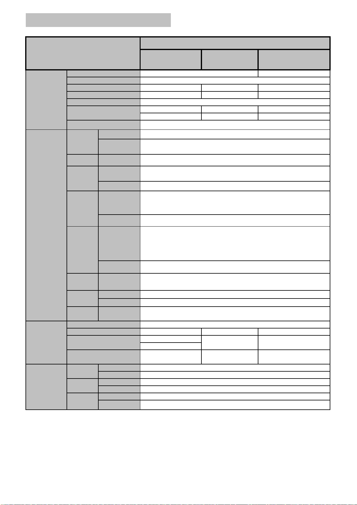
PDP TV
r
Specifications
Item
42" SD 50" HD42" HD
Display
In / Out
Terminals
Screen Size(Active Area)
Aspect ratio
Number of Pixels
Pixel Pitch
Displayable Colors
Brightness
Viewing Angle
Speaker
Output
RS-232C
HDMI
Input
RGB
Input
Internal Speaker
External
Speaker
3.5mm Jack
HDMI Jack
RCA-pin x 1
D-Sub 15-pin x1
Ear Jack x 1
RCA-pin x 2
Component
Input
42" (920.1(H) x 518.4(V)±5mm)
16:9
852 (H) x 480 (V) 1024 (H) x 768 (V)
1.080(H) x 1.080(V) [mm] 0.900(H) x 0.676(V) [mm]
16.7 Million Colors
1500 cd/㎡
10000:1
10W(L) + 10W(R) [RMS] / 8 Ω
10W(L) + 10W(R) [RMS] / 8 Ω
2 Way 3 Speaker System
TXD/RXD
Digital RGB : TMDS
MAX : 1920 x 1080i
Audio : 0.5V[rms] (L+R)
RGB:0.7V[p-p](75Ω), H/CS/V:TTL (2.2 kΩ), SOG:1V[p-p](75Ω)
MAX : 1024 X 768 / 60 Hz (XGA)[42"] , 1360 X 768 / 60 Hz (nVidia
Only)[50"]
Audio : 0.5V[rms] (L+R)
Y:1V[p-p](75Ω) , Pb/Cb:0.7V[p-p](75Ω) , Pr/Cr:0.7V[p-p](75Ω)
SDTV : 525i (480i), 625i(576i), 525p(480p), 625p(576p)
HDTV : 750p(720p), 1125i(1035i,1080i)
1200 cd/㎡
8000:1
Over 160 degrees
50" (1106.5(H) x 622.1(V)±5mm)
1366 (H) x 768 (V)
0.810(H) x 0.810(V) [mm]
1000 cd/㎡
8000:1
Audio : 0.5V[rms] (L+R)
Y: 1V[p-p] ( 75 Ω) , C: 0.286V[p-p] ( 75 Ω)[NTSC]
Y: 1V[p-p] ( 75 Ω) , C: 0.3V[p-p] ( 75 Ω)[PAL]
Video : 1V[p-p] ( 75 Ω) [ NTSC/PAL]
Audio : 0.5V[rms] (L+R)
Analog Air/Cable (75 Ω) [Unbalanced]
NTSC/PAL - M/ N
S-Video
Input
Video
Input
Antenna
Input
RCA-pin x 2
Mini DIN 4-pin x1
RCA-pin x 2
RCA-pin x 2
F - Type x 1
Power Supply
290W
1028 x 625 x 89.8
1028 x 625 x 107.4
34.8 Kg
General
Environment
Condition
Power Consumption (Typical)
Dimensions (Without Stand)
[ W mm x H mm x D mm ]
Weight (Without Stand)
Temperatu
Humidity
Pressure
Operational
Stora
e
Operational
Stora
e
Operational
Storage
* The specifications are subject to change without notice
AC 100V ~ 240V, 50/60Hz
350W
1028 x 625 x 107.4
35.8 Kg
0 ~ 40 ℃
-20 ~ 60 ℃
20 ~ 80% RH (No condensation)
10 ~ 90% RH (NO condensation)
800 ~ 1100 hPa (Altitude : 0 ~ 2,000 m)
700 ~ 1100 hPa (Altitude : 0 ~ 3,000 m)
450W
1205 x 721 x 117.3
42 Kg
Page 6
m
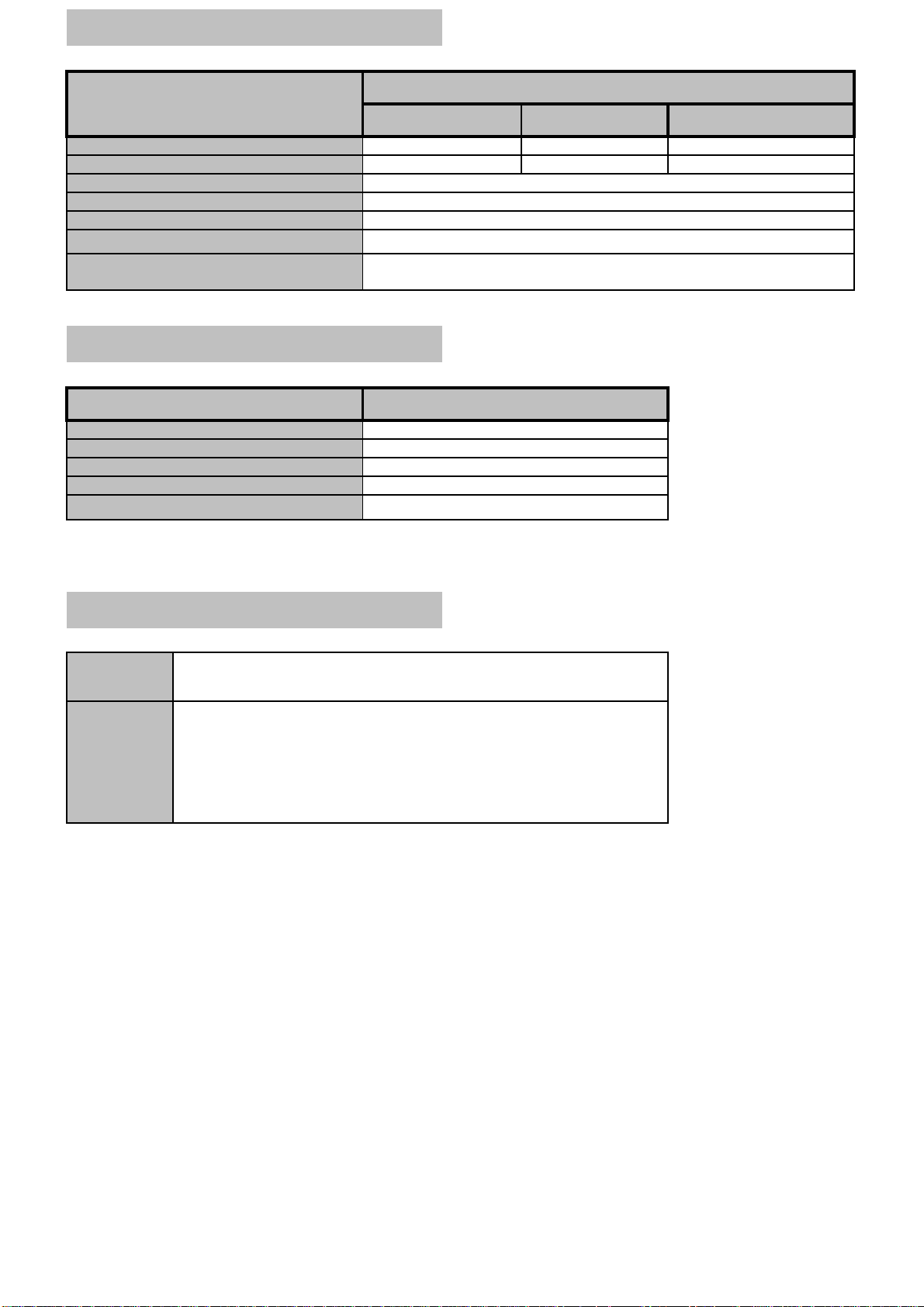
External Speaker (Optional)
e
l
e
c
Item
42" (A) 42" (B)
Dimensions (W mm x H mm x D
Weight
Typ
Input
Impedence
Output Sound Pressure
113 x 626.6 x 82.2
5 Kg ( L + R )
Specifications
90 x 625 x 68
2.9 Kg (L+R)
2 Way 3 Speaker System
10 W ( RMS)
8 Ω
87 dB/W/M
0 mm x 721 mm x 68 m
50"
3 Kg ( L + R )
Frequency Response
Internal Speaker (Optional)
Item
Typ
Input
Impedence
Output Sound Pressure
Frequency Response
* The specifications are subject to change without notice
Specifications
1 Way 1 Speaker System
Accessories
Standard
Optional
Owner's Instruction , Remote Controller/AAA Batteries , Antenna Cab
Power Cord , Speaker Cable
Foot Stand , Table-Top stand , Wall-Mount Bracket , Ceiling-Mount Bra
Internal Speaker System , External Speaker System ,
HDMI Cable , VGA(D-SUB) Cable , Audio Cable , Component Cable ,
RCA Video/Audio Cable , S-Video Cable
45 Hz ~ 20 KHz
10 W ( RMS)
8 Ω
88 dB/W/M
140 Hz ~ 10 KHz
* The specifications are subject to change without notice
Page 7
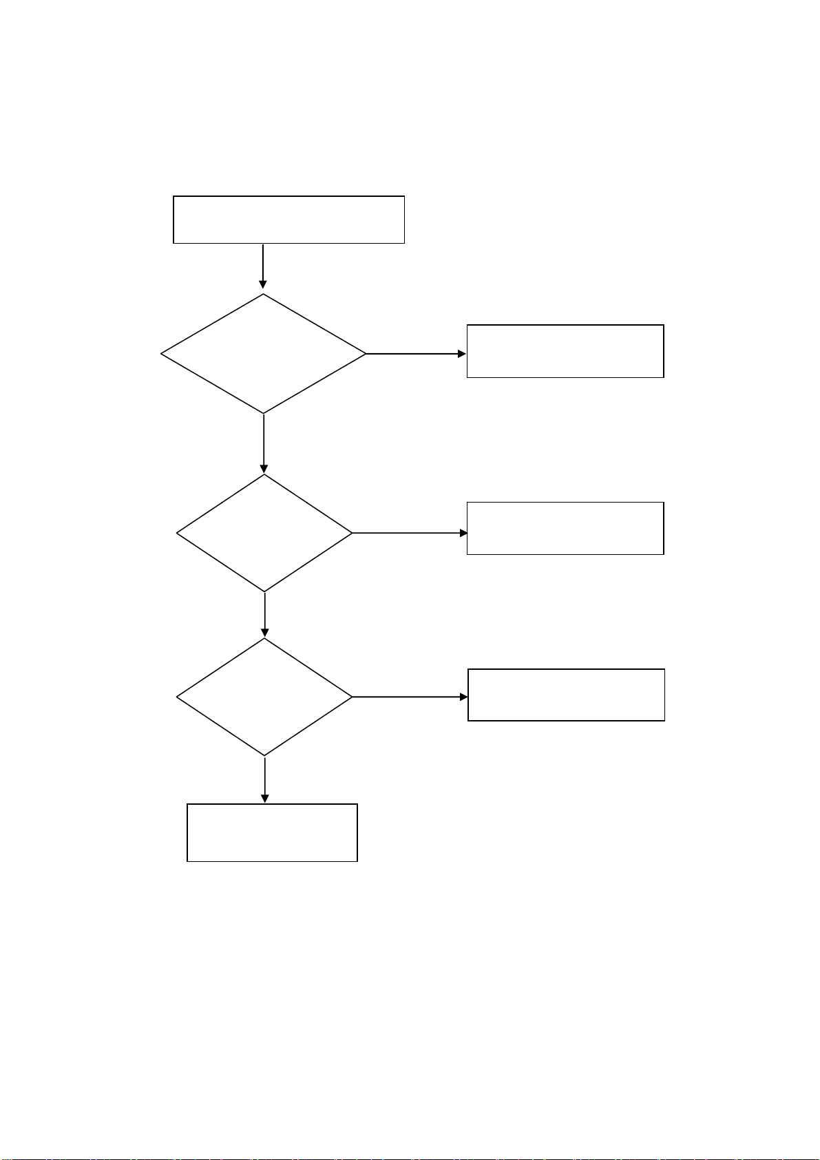
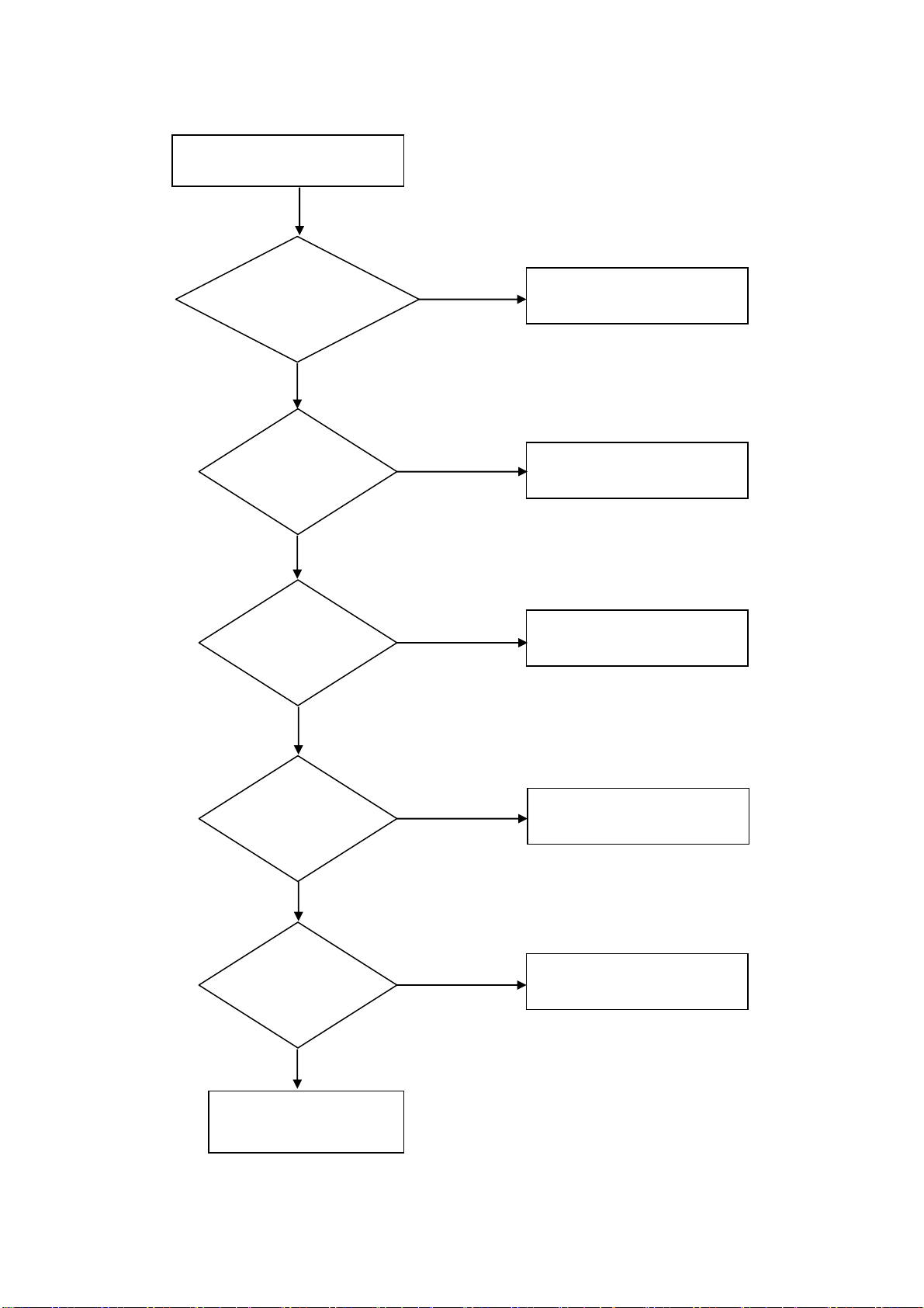
Image Board Trouble Shooting Guide
Abnormal TV Signal
Replace RF Cable
/ Check
NO
Replace Sub
(Tuner) Board
/ Check
NO
Replace
Main Board
/ Check
YES
YES
YES
Replace Cable
Replace Sub Board
Replace Main Board
NO
Replace PDP Module
Page 8
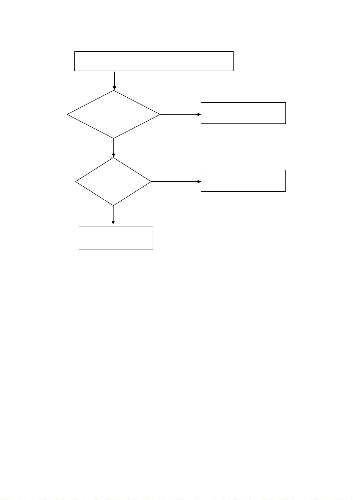
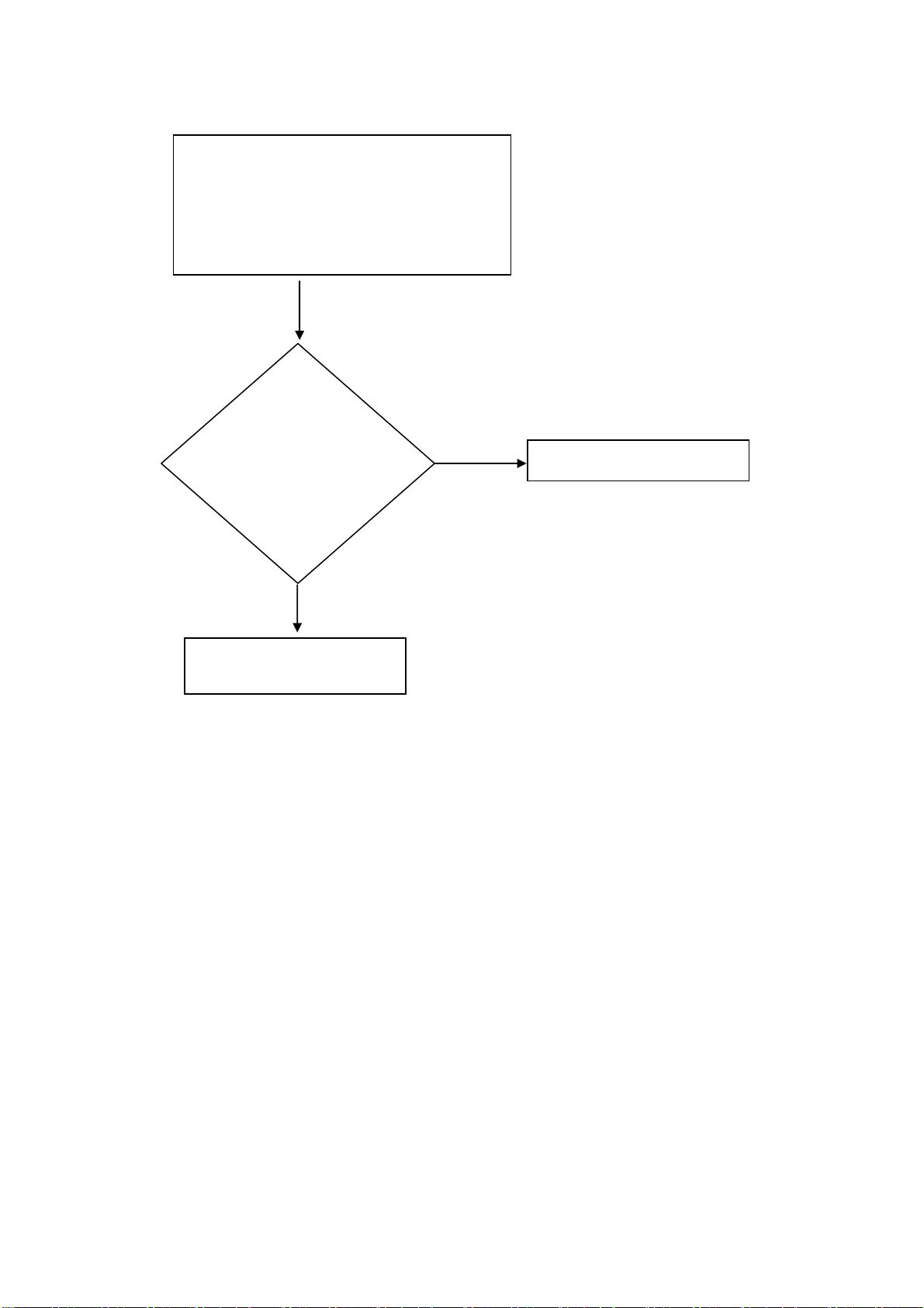
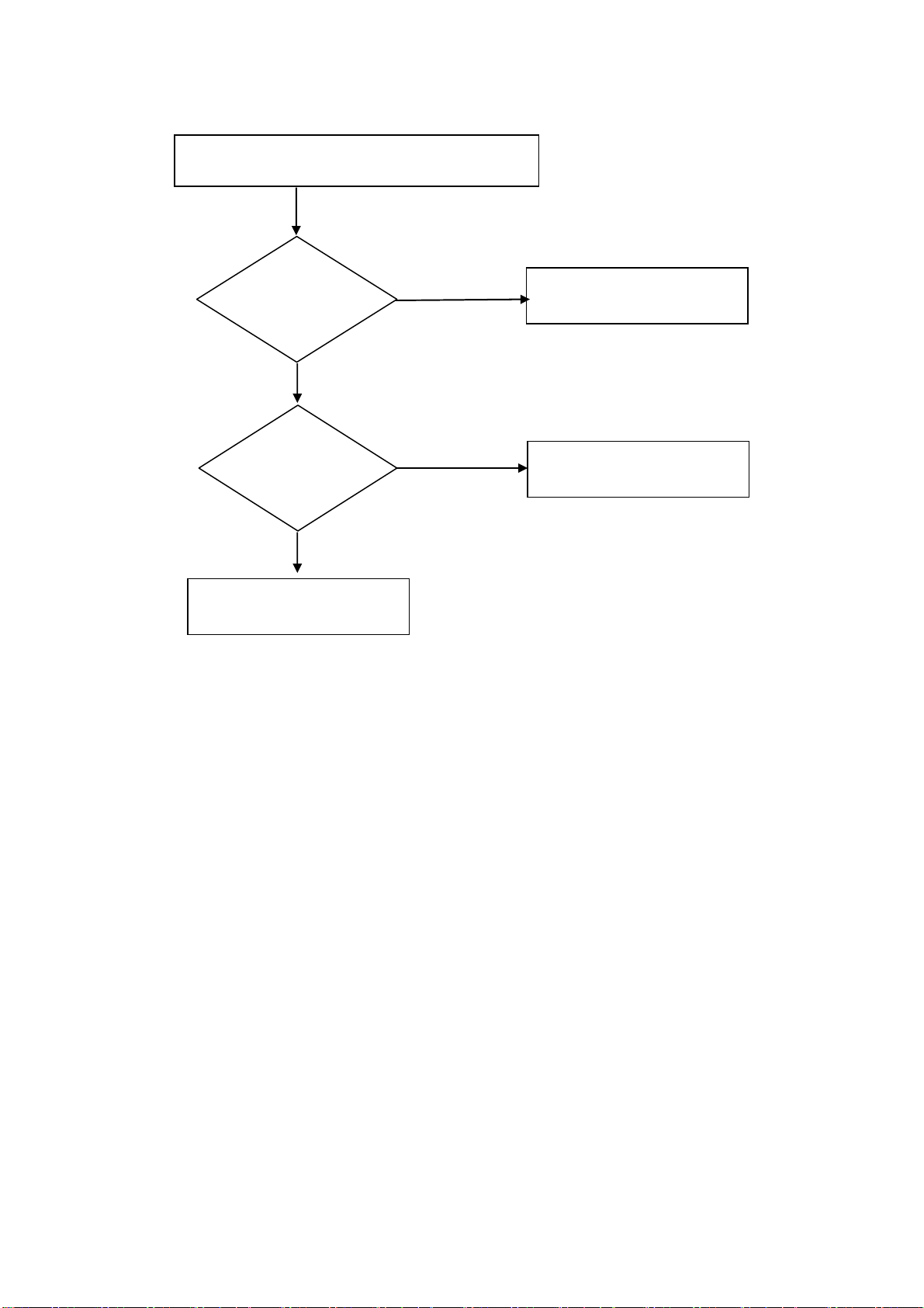
Abnormal HDMI, RGB, Component Video Signal
Replace HDMI,
RGB, RCA Cable
/ Check
NO
Replace
Main Board
/ Check
NO
Replace PDP Module
YES
YES
Replace Cable
Replace Main Board
Page 9
Abnormal Audio Signal
- HDMI (RCA Jack),
PC RGB (3.5mm Stereo),
Component (RCA Jack)
Replace
RCA Cable (HDMI)
3.5mm Cable(PC),
RCA Cable (ComponentI)
/ Check
NO
YES
Replace Cable
Replace Main Board
Page 10
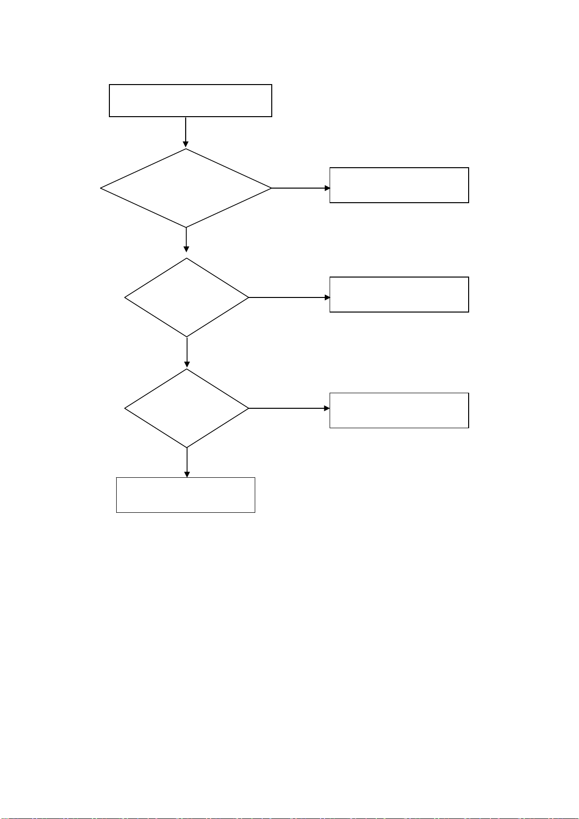
Abnormal S-Video Video Signal
Replace S-Video Cable
/ Check
NO
Replace
Sub Board
/ Check
NO
Replace
Main Board
/ Check
NO
YES
YES
YES
Replace Cable
Replace Sub Board
Replace Main Board
Replace PDP Module
Page 11
Abnormal Video Signal
Replace
RCA Cable
/ Check
NO
Replace
Sub Board
/ Check
NO
Replace
Main Board
/ Check
YES
YES
YES
Replace Cable
Replace Sub Board
Replace Main Board
NO
Replace PDP Panel
Page 12
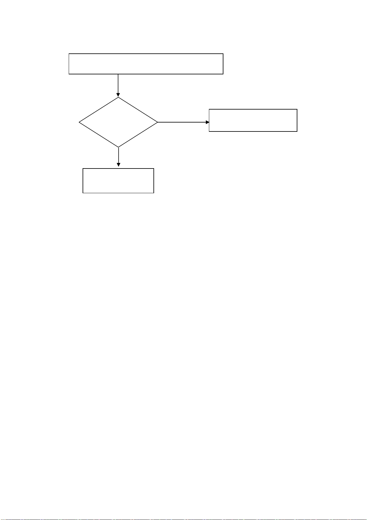
TV Main is displayed, but Caption is Failed
Replace Sub
(Tuner) Board
/ Check
NO
Replace Main Board
YES
Replace Sub Board
Page 13
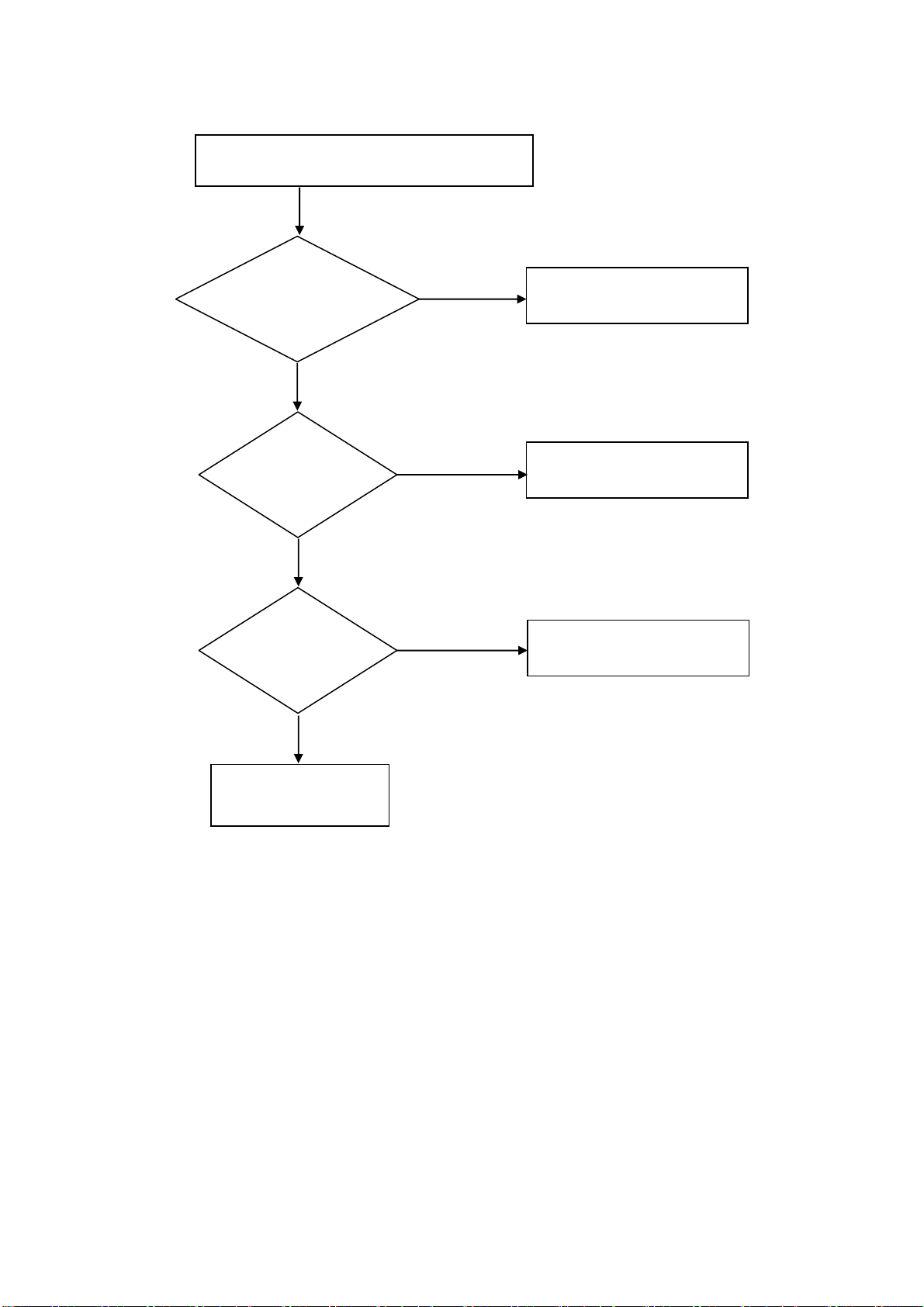
Power On Failure
Replace
Connector Ass'y
/ Check
NO
Replace
Control Board
/ Check
NO
Replace
Power Board
/ Check
YE
YES
YES
Replace Connector Ass'y
Replace Control Board
Replace Power Board
NO
Replace
Main Board
/ Check
NO
Replace
Sub Board
/ Check
NO
Replace PDP Module
YES
YES
Replace Main Board
Replace Sub Board
Page 14
None Working Control Key, LED, IR
Replace
Connector Ass'y
/ Check
NO
Replace
Control Board
/ Check
NO
Replace Main Board
YES
YES
Replace Cable
Replace Control Board
Page 15

WoosungNextier Corp.
------------------------------------------------------------------------------------------------------------
Engineering Product Specification
(MODEL : NP – 42S5, NP-42H5, NP-50H5)
PDP – TELEVISION
Page 16

TABLE OF CONTENTS
1. SCOPE
1.1 Introduction.
1.2 Product Definition.
1.3 Mass Production Release.
1.4 Change Control.
1.5 Service.
2. GENERAL SPECIFICATION
2.1 General Spec.
2.2 Input / Output Terminal.
3. INPUT SIGNAL INTERFACE
3.1 HDMI Signal Interface.
3.2 RGB Signal Interface.
3.3 RGB/HDMI Mode Table.
3.4 Component Signal Interface.
3.5 Component Mode Table.
3.6 S-Video Signal Interface.
3.7 Composite Signal Interface.
3.8 Antenna Signal Interface.
4. POWER
4.1 Power Supply.
5. CONTROLS AND INDICATORS
5.1 Hardware Control.
5.2 Remote control.
5.3 Menu Control
6. PLASMA DISPLAY PANEL(PDP) Specifications
Page 17

6.1 42”SD Specifications
6.2 42”HD Specifications
6.3 50”HD Specifications
7. DISPLAY CELL DEFECT SPECIFICATION
7.1 42”SD Cell Defect Specifications
7.2 42”HD Cell Defect Specifications
7.3 50”HD Cell Defect Specifications
8. MECHANICAL
8.1 Fan.
8.2 Dimension.(without stand)
8.3 Weight.
9. ENVIRONMENTAL
9.1 42”SD Environmental Conditions.
9.2 42”HD Environmental Conditions.
9.3 50”HD Environmental Conditions.
10. PACKAGING
10.1 Packaging Specifications.
10.2 Vibration.
10.3 Drop.
11. AUDIO SYSTEM
11.1 External Speaker System.
11.2 Internal Speaker System.
Page 18
1. SCOPE
1.1 Introduction
Product configuration
Plasma Displays
1.2 Product Definition
Top Level Assembly
This specification defines the configuration and performance
requirements for the following Plasma
Displays.
Product Name : PDP-TELEVISION
Display Type : 42” SD / 42” HD / 50” HD
Model Name : NP – 42S5 / NP-42H5 / NP-50H5
The top level assembly shall contain :
1. Plasma Display : NP – 42S4 / NP-42H4 / NP-50H4
2. Power Cord 1.8M (Option by buyer)
3. Antenna Cable(NTSC) (Option)
4. Remote Control Unit
5. “AAA” Batteries N=2
6. Owner’s Instructions
7. External Speaker Cable
(Include in the External Speaker System)
8. Foot Stand / Table-Top Stand (Option)
9. Wall-Mount Bracket (Option)
10. Internal Speaker System (Option)
11. External Speaker System (Option)
12. Speaker Stand (Option)
1.3 Mass Production Release
Mass Production Approval
Component Approvals
Mass Production shall not begin until Woosung
Nextier Corp. has issued a Mass Production
Release.
All exterior plastic components, screen printed components,
labels, shipping cartons, protective foam, and printed
materials require approvel by WoosungNextier Corp. prior to
Mass production Release.
Page 19

1.4 Change Control
All Engineering changes to the product shall be made in
ECR/ECN
1.5 Service
Documentation / Service Manual
accordance with the WoosungNextier Corp. ECR/ECN
Procedure
Complete Spare Parts List, Schematic, Service Manual, and
Assembly Drawings shall be provided within one month of
Mass Production Release.
Page 20
2. GENERAL SPECIFICATION
2.1 General Spec.
Display Type 42”SD 42”HD 50”HD
Model Name
Native Resolution & Frequency
NP-42S5 NP-42H5 NP-50H5
852 X 480 @ 60Hz 1024 X 768 @ 60Hz 1366x768 @ 60Hz
AC100V ~ 240V,
AC100V ~ 240V,
Input Voltage
50/60Hz
2.2 Input/Output Terminal
HDMI Jack x 1
HDMI Input
RGB Input
Component Input
Audio Line Output (Analog) RCA Jack(L+R) × 1
S-Video Input Mini DIN S-terminal × 1
(Type A)
RCA Jack(L+R) × 1
D-Sub 15-pin Jack ×1
3.5MM STEREO Jack(L+R) × 1
RCA(YPbPr/YCbCr) Jack × 2
RCA(L+R) Jack × 2
50/60Hz
AC100V ~ 240V,
50/60Hz
Composite Input RCA Jack × 2
Antenna Input F-Type × 1
RS-232C 3.5mm Jack × 1
Page 21
3. INPUT SIGNAL INTERFACE
3.1 HDMI Interface
HDMI Input Connector Type A Female Contacts
Type A Connector Pin Assignment Pin 1 TMDS Data 2+
Pin 2 TMDS Data 2 Shield
Pin 3 TMDS Data 2-
Pin 4 TMDS Data 1+
Pin 5 TMDS Data 1 Shield
Pin 6 TMDS Data 1Pin 7 TMDS Data 0+
Pin 8 TMDS Data 0 Shield
Pin 9 TMDS Data 0Pin 10 TMDS ClockPin 11 TMDS Clock Shield
Pin 12 TMDS ClockPin 13 CEC
Pin 14 Reserved(N.C. on device)
Pin 15 SCL
Pin 16 SDA
Pin 17 DDC/CEC Ground
Pin 18 +5V Power
Pin 19 Hot Plug Detect
Sync Signals Digital RGB : TMDS (Video + Audio)
Audio - 48kHz / 2 Channel (L + R)
DDC 1/2B EDID 1.3
Audio Input Connector RCA (L+R) Jack
Page 22
3.2 RGB Interface
RGB Input Connector D-Sub 15-Pin Jack (Female)
Audio Input Connector 3.5mm Stereo Jack
D-Sub 15-Pin Cable Connector Pin out
Pin 1 Red analog Signal
Pin 2 Green analog Signal
Pin 3 Blue analog Signal
Pin 4 GND
Pin 5 GND
Pin 6 GND for Red signal
Pin 7 GND for Green signal
Pin 8 GND for Blue signal
Pin 9 NC
Pin 10 GND
Pin 11 GND
Pin 12 SDA (Input only)
Pin 13 H-Sync or composited H/V Sync Signal
Pin 14 V-Sync
Pin 15 SCL (Input only)
RGB Signals 700 mV full scale
RGB Signal Impedance 75 Ohms
RGB Audio Input Level 0.5V[rms] (L+R)
RGB Audio Output Level 0.5V[rms] (L+R)
RGB Sync Signals TTL 2.2k ohm internal pull-up resistors.
DDC 1/2B VER 1.3(Option)
Page 23

3.3 RGB Mode Table
Mode Resolution Horizontal
Frequency(kHz)
VGA
640 x 400 37.861 85.08 31.500
640 x 480
SVGA 800 x 600
XGA
1024 x 768
31.469 70.087 25.175 640 x 350
37.861 85.08 31.5
31.469 70.087 28.322 720 x 400
37.927 85.039 35.5
31.469 59.94 25.175
37.861 72.809 29.765
37.500 75.000 31.500
35.156 56.25 36.0
37.879 60.317 40.0
43.764 70.020 45.5
48.077 72.188 50.0
46.875 75.0 49.5
48.780 60.001 64.11
Vertical
Frequency (Hz)
Pixel Clock Frequency
(MHz)
48.363 60.004 65.0
56.476 70.069 75.0
60.030 75.029 78.75
60.241 74.927 80
1280 x 768 47.700 60.0 80.136
1360 x 768
(nVidia
only)
SDTV 576p 720 x 576 31.250 50.000 26.566
HDTV 1080i 1920 x 1080
60.000
31.469 59.94 25.175 SDTV 480p 720 x 480
31.5 60 27.027
44.964 59.94 74.176 HDTV 720p 1280 x 720
45 60 74.25
33.750 60.0 74.25
33.176 59.94 74.176
28.125 50.0 74.25
31.25 49.96 74.25
Page 24
3.4 Component Interface
Component Input Connector RCA(YPbPr/YCbCr) Jack x 2
Audio Input Connector RCA(L+R) Jack x 2
Component Signal Y : 1V[p-p]
Pb/Cb : 0.7V[p-p]
Pr/Cr : 0.7V[p-p]
Component Signal Impedance 75 Ohms
Audio Input 0.5[rms] (L+R)
Audio Input Impedance 470K Ohms
Component Signal Type SDTV : 525i(480i), 625i(576i )
EDTV : 625p(576p), 525p(480p)
HDTV : 750p(720p), 1125i(1035i, 1080i)
3.5 Component/HDMI Mode Table
Mode Resolution Horizontal
Frequency
(kHz)
SDTV 480i 720 x 480 15.730 29.970 13.5000
SDTV 575i 720 x 576 15.630 25.000 13.5000
31.469 59.94 25.175 EDTV 480p 720 x 480
31.5 60 27.027
EDTV 575p 720 x 576 31.250 50.000 26.566
44.964 59.94 74.176 HDTV 720p 1280 x 720
45 60 74.25
HDTV 1080i 1920 x 1080
33.750 60.0 74.25
33.176 59.94 74.176
28.125 50.0 74.25
31.25 49.96 74.25
Vertical
Frequency
(Hz)
Pixel Clock Frequency
(MHz)
Page 25
3.6 S-Video Interface
S-Video Input Connector Mini DIN4-pin
S-Video Signal Y : 1V[p-p]
C : 0.286V[p-p] (NTSC)
C : 0.3V[p-p] (PAL/SECAM)
S-Video Signal Impedance 75 Ohms
3.7 Composite Interface
Composite Input Connector RCA(Video) J ack x 2
Audio Input Connector RCA(L+R) Jack
Composite Input Signal V : 1V[p-p]
Composite Audio Input Level 0.5[rms] (L+R)
Composite Input Signal Impedance 75 Ohms
Composite Audio Input Impedance 470K Ohms
3.8 Antenna Interface
Antenna Input Connector F - Type x 1
Antenna Input Signal
Channel Coverage VHF Low Band : 54.00 ~ 132.00 MHz
NTSC-M/PAL-M/N
Analog Air / Cable (75 ohm) [Unbalanced]
VHF High Band : 132.00 ~ 366.00 MHz
UHF Band : 366.00 ~ 806.00 MHz
Page 26

4. POWER
4.1 Power Supply
Model Name NP-42S5 NP-42H5 NP-50H5
Input Voltage Range AC 100 ~ 240V AC 100 ~ 240V AC 100 ~ 240V
Input Frequency Range 50/60 Hz 50/60 Hz 50/60 Hz
Power Consumption Tpy : 290W
Standby : 7 W
Tpy : 350W
Standby : 7 W
Tpy : 450W
Standby : 7 W
Page 27
5. CONTROLS AND INDICATORS
5.1 Hardware Controls
Main Power Switch None
LED Power / Standby : Red
Operation Lamp : Green
Controls Switch Input
Menu
VOL-
VOL+
CH-
CH+
Power
Infrared Receiver Arrival Distance : Min 7m
Resonance Frequency : 38 KHz
5.2 Remote Control
Distance 7 m
Angle 30 degrees angle on each side of the sensor
Page 28

5.3 Menu Controls
TV /
Video/
S-Video/
Component/
HDMI
Input
Picture Size [Wide/Panorama/Zoom/4:3/14:9]
Picture Mode [Standard/Movie/Mild/Custom/Dynamic]
Brightness, Contrast, Sharpness, Tint, Color
Color Tone [Normal/Warm1/Warm2/Cool1/Cool2]
Channel Air/Cable/Hrc/Irc
Auto Search
Add/Delete
Fine Tune
Sound Sound Mode [Standard/Music/Movie/Speech/Custom]
Equalizer
Auto Volume [On/Off]
PIP PIP [On/Off]
Input Source
Size
Position
Swap
Setup Time
RGB
Input
Clock
On Timer
Off Timer
Sleep Timer
On Time Channel
On Time Volume
Blue Screen
Language
DNR
Screen Wiper
Pixel Shift
Caption
V-Chip
Picture Size [Wide/4:3/Real]
Picture Mode [High/Middle/Low]
Brightness
Contrast
Sharpness
Page 29

Color Tone
Picture PC
Auto in Progress
Reset
Position
Frequency
Phase
Page 30

6. PLASMA DISPLAY PANEL (PDP) SPECIFICATIONS
6.1 42” SD Specifications
Panel Type 42V7
Number of Pixels 852(H) × 480(V) pixels (1pixel = 3 RGB cells)
Pixel Pitch 1.080 mm (H) × 1.080 mm (V)
Cell Pitch 0.320 mm (H) × 1.080mm (V)
Display Area 920.1mm (H) × 518.4mm (V) ± 0.5mm
Outline Dimension 1005(H) × 597(V) × 60.6(D) ± 1mm
Pixel Type RGB Closed type
Number of Gradations (R)1024 × (G)1024 × (B)1024
Aspect Ratio 16:9
Peak Brightness Typical 1,500cd/㎡
Contrast Ratio(in Dark Room) Typical 10,000:1
Life-time More than 60,000 Hours of continuous operation
6.2 42” HD Specifications
Panel Type 42X3
Number of Pixels 1024(H) × 768(V) (1pixel=3 RGB cells)
Pixel Pitch 0.900 mm (H) × 0.676 mm (V)
Cell Pitch 0.300 mm (H) × 0.676 mm (V)(Green Cell basis)
Display Area 920.1mm (H) × 518.4mm (V) ± 0.5mm
Outline Dimension 1005(H) × 597(V) × 60.6(D) ± 1mm
Pixel Type RGB Closed type
Number of Gradations (R)1024 × (G)1024 × (B)1024
Aspect Ratio 16:9
Peak Brightness Typical 1,500cd/㎡
Contrast Ratio(in Dark Room) Typical 10,000:1
Expected Life-time More than 60,000 Hours of continuous operation
Page 31

6.3 50” HD Specifications
Panel Type 50X3
Number of Pixels 1366(H) × 768(V) (1pixel=3 RGB cells)
Pixel Pitch 0.810 mm (H) × 0.810 mm (V)
Cell Pitch 0.270 mm (H) × 0.810 mm (V)(Green Cell basis)
Display Area 1106.5mm (H) × 622.1mm (V) ± 0.5mm
Outline Dimension 1190(H) × 700(V) × 58(D) ± 1mm
Pixel Type RGB Closed (Well)type
Number of Gradations (R)1024 × (G)1024 × (B)1024
Aspect Ratio 16:9
Peak Brightness Typical 1,000cd/㎡
Contrast Ratio(in Dark Room) Typical 8,000:1
Expected Life-time More than 60,000 Hours of continuous operation
Page 32

7. Display Cell Defect Specification
7.1 42” SD Cell Defect Specifications
☞1) Non-Ignition Dot(Dark Defect) is defined as “A cell of which more than 50% area is not ignited”
☞2) Unstable Dot (Flickering) is defined as “A cell which repeats On and Off”
☞3) Uncontrollable Dot is defined as “A cell which is distinctly brighter or darker than other cells around it” and/or
“A cell of which color is distinctly different from that of other cells around it”
☞4) Non-Extinguishing Dot (brightness defect) is defined as “A cell of which more than 50% area is always ON”
☞5) Stain is defined as “A blob due to local color contamination in white or simple color pattern”
Page 33

7.2 42” HD Cell Defect Specifications
☞1) Non-Ignition Dot(Dark Defect) is defined as “A cell of which more than 50% area is not ignited”
☞2) Unstable Dot (Flickering) is defined as “A cell which repeats On and Off”
☞3) Uncontrollable Dot is defined as “A cell which is distinctly brighter or darker than other cells around it” and/or
“A cell of which color is distinctly different from that of other cells around it”
☞4) Non-Extinguishing Dot (brightness defect) is defined as “A cell of which more than 50% area is always ON”
☞5) Stain is defined as “A blob due to local color contamination in white or simple color pattern”
Page 34

7.3 50” HD Cell Defect Specifications
☞1) Non-Ignition Dot(Dark Defect) is defined as “A cell of which more than 50% area is not ignited”
☞2) Unstable Dot (Flickering) is defined as “A cell which repeats On and Off”
☞3) Uncontrollable Dot is defined as “A cell which is distinctly brighter or darker than other cells around it” and/or
“A cell of which color is distinctly different from that of other cells around it”
☞4) Non-Extinguishing Dot (brightness defect) is defined as “A cell of which more than 50% area is always ON”
☞5) Stain is defined as “A blob due to local color contamination in white or simple color pattern”
Page 35

8. MECHANICAL
8.1 Fan
Fans N/A (No Fans are used in the unit)
8.2 Dimensions (without stand)
Model Name NP-42S5 NP-42H5 NP-50H5
Width
Height
Depth
1028mm 1028mm 1205mm
625mm 625mm 721mm
89.8mm [A-type]
107.4mm[B-type]
107.4mm 114.3mm[C-type]
114.3mm[D-type]
8.4 Weight(without stand)
Model Name NP-42S4 NP-42H4 NP-50H4
Net Weight 29Kg 31.0Kg 43Kg
9. ENVIRONMENTAL
9.1 42”SD Environmental Conditions
Operating Temperature Range 0°C to +55°C
Storage Temperature -20°C to 60°C (Packing condition)
Operating Relative Humidity 20% to 80% (Non-Condensing)
Storage Relative Humidity 10% to 90% (Non-Condensing)
Operating Atmospheric Pressure 800~1100hpa (Altitude : 0 ~ 2,000 m)
Storage Atmospheric Pressure 700~1100hpa (Altitude : 0 ~ 3,000 m)
9.2 42”HD Environmental Conditions
Operating Temperature Range 0°C to +40°C
Storage Temperature -20°C to 60°C (Packing condition)
Operating Relative Humidity 20% to 80% (Non-Condensing)
Storage Relative Humidity 10% to 90% (Non-Condensing)
Operating Atmospheric Pressure 800~1100hpa (Altitude : 0 ~ 2,000 m)
Storage Atmospheric Pressure 700~1100hpa (Altitude : 0 ~ 3,000 m)
Page 36

9.3 50”HD Environmental Conditions
Operating Temperature Range 0°C to +40°C
Storage Temperature -20°C to 60°C (Packing condition)
Operating Relative Humidity 20% to 80% (Non-Condensing)
Storage Relative Humidity 10% to 90% (Non-Condensing)
Operating Atmospheric Pressure 800~1100hpa (Altitude : 0 ~ 2,000 m)
Storage Atmospheric Pressure 700~1100hpa (Altitude : 0 ~ 3,000 m)
10. PACKAGING
10.1 Package Specifications
Model Name NP-42S5 NP-42H5 NP-50H5
Ink The ink shall not rub off after a suitable drying time.
Shipping Carton Type One Piece Construction
Carton Material Double Wall
Handle Cartons shall incorporate four holes on sides sides for
Width TBD TBD TBD
Height TBD TBD TBD
Depth TBD TBD TBD
Gross Weight TBD TBD TBD
Vertical Flute
16 kg/cm2 burst strength.
handling.
10.2 Vibration
Bottom Back and Sides
Vibration Frequency 5-30Hz 30-50Hz 5-50Hz
Acceleration 1.1G 0.7G 0.7G
Duration 15minutes / 1 cycle 15minutes / 1 cycle
Test Time 75minutes 15minutes
Vibration Test Data
10.3 Drop
Bottom 30cm
Four Bottom Edges (one side support) 40cm (another side edge support at 15cm height )
Drop Test Data
Page 37

11. AUDIO SYSTEM
11.1 External Speaker System (Option)
NP-42S5 NP-42H5 NP-50S5
Dimension(W × H × D) 113 mm × 626.6 mm × 82.2 mm 90 mm × 721 mm × 68 mm
Weight 5 kg (L+R) 3 kg (L+R)
Type 2 Way 6 Speaker System
Input 10 W (RMS)
Impedence 8 ohm
Output Sound Pressure 87 dB/W/M
Frequency Response 45 Hz ~ 20 KHz
11.2 Internal Speaker System (Option)
Type 2 Way 2 Speaker System
Input 10 W (RMS)
Impedence 8 ohm
Output Sound Pressure 88 dB/W/M
Frequency Response 140 Hz ~ 10 KHz
Page 38

Control Board
LED
IR
HDMI
COMPONENT1
COMPONENT2
S-Video
AV1
AV2
TV
RS-232C
HDMI Input
RGB Input
Component
Input
S-VIDEO
CVBS
CVBS
TUNER
RXD
TXD
EEPROM(DDC)
EEPROM(DDC)
Component_2IN
HDMI IN
RGB_IN
Component_1IN
MUX
AV1-S
AV1
AV2
CVBS
E2PROM
ADC
TMDS
MST3388M
VIDEO
DECODER
(3D COM
FILTER
TW9919
(6Y2C)
VCHIP ZILOG
Z86129
CAPTION
I2S HDMI AUDIO
24BIT RGB
CCIR656
SDRAM
(1M*16 OR
4M*16)
Ver.01
A
PROM
SRAM
EEPROM
2006.03.16
DDR Flash ROM
SCALER
PW218
E2PROM
INPU
T
LVDS1
LVDS2
2LED
7KEY
RCU
RECEIVER
MUX
UART FOR
A/S
MENU
-VOL +
CON
CON
-CH +
LG PDP
PANEL
Audio PC
HDMI
COMPONENT 1
COMPONENT 2
AV1/S-VIDEO
AV2
AUDIO OUT
L R
L R
L R
L R
L R
L R
TUNER
AUDIO
V
AUDIO
AUDIO
AUDIO
AUDIO
AUDIO
SIF
STEREO JACK
AUDIO
AUDIO
PROCESSOR
MICRONAS MSP4440K
OR
MICRONAS MSP4410K
I2S HDMI AUDIO
AUDIO AMP
MAX10W*2
TDA7262
A
CON
Rint
Lint
POWER
R
Internal
Speaker
Output
L
AUDIO PART
Page 39

5
D D
4
3
2
1
Project : 218 Main
Version : A1
C C
B B
Confidential
A A
Date
Date
CONFIDENTIAL
CONFIDENTIAL
Title
Title
Title
01 Cover story
01 Cover story
01 Cover story
Designer
Designer
Designer
Address
Address
5
4
3
2
Address
CONFIDENTIAL
Date
Friday, February 10, 2006
Friday, February 10, 2006
Friday, February 10, 2006
110
110
110
Sheet
Sheet
Sheet
Size Document NumberRev
Size Document NumberRev
Size Document NumberRev
A1
A1
A1
A3
A3
A3
Note
Note
Note
LAB 3
LAB 3
LAB 3
1
of
of
of
<Doc>
<Doc>
<Doc>
Page 40

5
Stby_5V
PC2_5V
JACK1
JACK1
20
20
21
CEC/DDC GND
21
22
22
23
Dat2 shield
23
Dat1 shield
Dat0 shield
HDMI Type A CON
HDMI Type A CON
TS
TS
JACK2
JACK2
W
W
R
R
3
SJB0213-W-W.R-N
SJB0213-W-W.R-N
TS
TS
JACK3
JACK3
DSUB 15P
DSUB 15P
TS
TS
+5V
HPD
DDC SCL
DDC SDA
CEC
NC
clk shield
DAT0+
DAT0-
DAT1+
DAT1-
DAT2+
DAT2-
CLK+
CLK-
1
2
SJ3512-5 _PC Audio in
SJ3512-5 _PC Audio in
TS
TS
D D
C C
B B
A A
D1
D1
BAV70L
BAV70L
18
19
15
16
13
14
17
2
5
8
11
7
9
4
6
1
3
10
12
TS
TS
1K_OHM_200MA
1K_OHM_200MA
FB25
FB25
FB26
FB26
1K_OHM_200MA
1K_OHM_200MA
TS
TS
16 17
JACK8
JACK8
DVI_5V
TS
TS
PC2_5V
DVI_DDC_SCL
DVI_DDC_SDA
C457
C457
15pF
15pF
C465
C465
C464
C464
15pF
15pF
15pF
15pF
T
T
T
T
NS
NS
NS
NS
6
1
11
7
2
12
8
3
13
9
4
14
10
5
15
B
b
C
c
E
e
F
f
D
d
R308
R308
1K
1K
B
B
NS
NS
PC2_5V
C454
C454
15pF
15pF
T
T
NS
NS
C467
C467
330pF
330pF
TS
TS
PC_R
PC_G
DDC1_DAT
PC_B
PC_HYNC
PC_5V
PC_VSYNC
DET_PC
DDC1_CLK
5
D6
D6
BAV99
BAV99
BS
BS
TS
TS
HPD
C456
C456
15pF
15pF
B
B
NS
NS
R309
R309
2k
2k
TS
TS
C455
C455
C458
C458
15pF
15pF
15pF
15pF
T
T
T
T
NS
NS
NS
NS
C468
C468
330pF
330pF
TS
TS
Stby_5V
PC_5V
FB27
FB27
0 BS
0 BS
FB28
FB28
0 BS
0 BS
FB29
FB29
0 BS
0 BS
FB30
FB30
1K_OHM_200MA
1K_OHM_200MA
BS
BS
FB31
FB31
1K_OHM_200MA
1K_OHM_200MA
BS
BS
DVI_5V DVI_5V
C461
C461
15pF
15pF
T
T
NS
NS
R644
R644
3.3k
3.3k
TS
TS
C462
C462
C459
C459
15pF
15pF
15pF
15pF
T
T
T
T
NS
NS
NS
NS
D13
D13
MMBZ5V6ALT1
MMBZ5V6ALT1
TNS
TNS
DSUB_5V
D20
D20
BAV70L
BAV70L
T
T
S
S
C469
C469
15pF
15pF
BNS
BNS
C481
C481
330pF
330pF
BS
BS
D11
D11
BAV99
BAV99
BS
BS
DVI_DDC_SCL 3
DVI_DDC_SDA 3
C463
C463
15pF
15pF
T
T
NS
NS
C471
C471
C470
C470
15pF
15pF
15pF
15pF
BNS
BNS
BNS
BNS
C482
C482
330pF
330pF
BS
BS
High Active
C460
C460
100nF
100nF
TS
TS
2
3
1
C472
C472
15pF
15pF
BNS
BNS
D21
D21
MMBZ5V6ALT1
MMBZ5V6ALT1
BNS
BNS
D12
D12
BAV99
BAV99
TS
TS
2 3
CHK_DVI 7
2
D14
D14
MMBZ5V6ALT1
MMBZ5V6ALT1
3
TNS
TNS
1
DSUB_5V
D15
D15
BAV99
BAV99
B
B
NS
NS
C473
C473
C474
C474
15pF
15pF
15pF
15pF
BNS
BNS
BNS
BNS
2
1
Q1
Q1
MMBT3904
MMBT3904
TS
TS
1
R327 1KTSR327 1K
R328 1KTSR328 1K
C475
C475
15pF
15pF
BNS
BNS
2
3
1
D22
D22
MMBZ5V6ALT1
MMBZ5V6ALT1
BNS
BNS
R318
R318
4.7K
4.7K
T
T
S
S
R331
R331
10K
10K
B
B
S
S
DVI_DDC_SCL3
DVI_DDC_SDA3
3
4
DVI_5V
R320
R320
R319
R319
10K
10K
10K
10K
R322
R322
100
100
BS
BS
R323
R323
100
100
BS
BS
HPD0 7
D2
D10
D10
BAV99
BAV99
BS
BS
TS
TS
C476
C476
15pF
15pF
BNS
BNS
D2
D3
BAV99
BAV99
BS
BS
DVI_L_IN 6
DVI_R_IN 6
R332
R332
10K
10K
B
B
S
S
4
D3
BAV99
BAV99
BS
BS
D17
D17
BAV99
BAV99
B
B
NS
NS
U42
U42
SCL6VCC
5
SDA
1
A0
2
A1
3
A2
AT24C02N
AT24C02N
BS
BS
PC_R_IN 6
PC_L_IN 6
D9
D9
BAV99
BAV99
BS
BS
D16
D16
BAV99
BAV99
B
B
NS
NS
Confidential
R338
R338
1K
1K
BS
BS
R339
R339
1K
1K
BS
BS
BS
BS
R333
R333
10K
10K
B
B
S
S
D4
D4
BAV99
BAV99
BS
BS
GND
BS
BS
U41
U41
SCL6VCC
5
SDA
1
A0
WP
2
A1
3
GND
A2
AT24C04
AT24C04
BS
BS
Stby_5V
D7
D7
D5
D5
BAV99
BAV99
BS
BS
D18
D18
BAV99
BAV99
B
B
NS
NS
8
7
WP
4
R335
R335
10K
10K
B
B
S
S
BAV99
BAV99
BS
BS
D19
D19
BAV99
BAV99
B
B
NS
NS
DSUB_5V
D8
D8
BAV99
BAV99
BS
BS
C477
C477
100nF
100nF
BS
BS
R334
R334
10K
10K
B
B
S
S
DVI_5V
8
7
4
R315 10TSR315 10
R314 10TSR314 10
R31310TS
R31310TS
R31210TS
R31210TS
R31110TS
R31110TS
R31010TS
R31010TS
R31610TS
R31610TS
R31710TS
R31710TS
DSUB_R 3
DSUB_G 3
DSUB_B 3
DET_PC 7 ADC_HS 3
Low Active
C466
C466
100nF
100nF
BS
BS
TS
TS
3
RX0P 3
RX0M 3
RX1P 3
RX1M 3
RX2P 3
RX2M 3
RXCP 3
RXCM 3
3
JACK5
JACK5
SHRCA-623-G.B.R
SHRCA-623-G.B.R
TS
TS
PC_HYNC
C479
C479
33pF
33pF
BS
BS
PC_VSYNC
C480
C480
33pF
33pF
BS
BS
D23
D23
BAV99
BAV99
B
B
NS
NS
4
10
Y
Y
2
Pb
Pb
Pr
Pr
5
6
11
Bottom
JACK6
JACK6
SHRCA-415-W.R
SHRCA-415-W.R
TS
TS
3 4
R
W
R
W
1 2
R
W
R
W
6
5
VADC3.3V
147
1 2
U43A
U43A
SN74LVC14APWR
SN74LVC14APWR
TS
TS
VADC3.3V
U43C
U43C
147
SN74LVC14APWR
SN74LVC14APWR
TS
TS
5 6
Y
Y
Pb
Pb
Pr
Pr
TOP
Stby_5V
93
8
71
3 4
9 8
R342
R342
10K
10K
B
B
S
S
D24
D24
BAV99
BAV99
B
B
NS
NS
C483
C483
15pF
15pF
B
B
NS
NS
Stby_5V Stby_5V Stby_5V
D25
D25
D26
D26
BAV99
BAV99
BAV99
BAV99
T
T
T
T
NS
NS
NS
NS
C489
C489
C490
C490
15pF
15pF
15pF
15pF
B
B
B
B
NS
NS
NS
NS
FB38
FB38
1K_OHM_200MA
1K_OHM_200MA
BS
BS
FB39
FB39
1K_OHM_200MA
1K_OHM_200MA
BS
BS
FB40
FB40
1K_OHM_200MA
1K_OHM_200MA
BS
BS
FB41
FB41
1K_OHM_200MA
1K_OHM_200MA
BS
BS
U43BTSU43B
147
TS
VADC3.3V
C478
C478
100nF
100nF
T
T
S
S
147
U43DTSU43D
TS
2
R343
R343
10K
10K
B
B
S
S
C484
C484
15pF
15pF
B
B
NS
NS
D27
D27
BAV99
BAV99
T
T
NS
NS
C491
C491
15pF
15pF
B
B
NS
NS
2
3
1
C496
C496
C495
C495
330pF
330pF
330pF
330pF
B
B
B
B
S
S
S
S
ADC_VS 3
2
High Active
DTV1_DET 7
DTV2_DET 7
C485
C485
15pF
15pF
B
B
NS
NS
R344
R344
75
75
B
B
NS
NS
R345
R345
75
75
B
B
NS
NS
PAL change points
FB35 HB-1M2012-121 BSFB35 HB-1M2012-121 BS
FB36 HB-1M2012-121 BSFB36 HB-1M2012-121 BS
FB37 HB-1M2012-121 BSFB37 HB-1M2012-121 BS
2
2
2
D29
D29
MMBZ5V6ALT1
1
3
1
C497
C497
330pF
330pF
B
B
S
S
11 10
MMBZ5V6ALT1
3
TNS
TNS
VADC3.3V
147
R347 1KBSR347 1K
R348 1KBSR348 1K
R349 1KBSR349 1K
R350 1KBSR350 1K
U43ETSU43E
TS
Title
Title
Title
Designer
Designer
Designer
Address
Address
Address
3
1
C498
C498
330pF
330pF
B
B
S
S
Signal
DETECT
GND
ESD Circuit in MUX
HB-1M2012-121
HB-1M2012-121
FB32
HB-1M2012-121
HB-1M2012-121
FB33
HB-1M2012-121
HB-1M2012-121
FB34
R346
R346
75
75
B
B
NS
NS
C493
C493
C492
C492
18pF
18pF
68pF
68pF
B
B
B
B
S
S
S
S
D30
D30
MMBZ5V6ALT1
MMBZ5V6ALT1
TNS
TNS
BS
DTV2_L_IN 6
BS
DTV2_R_IN 6
BS
DTV1_R_IN 6
BS
DTV1_L_IN 6
U43FTSU43F
147
TS
13 12
02 Graphic Input
02 Graphic Input
02 Graphic Input
BSFB32
BS
BSFB33
BS
BSFB34
BS
C494
C494
18pF
18pF
B
B
S
S
D31
D31
MMBZ5V6ALT1
MMBZ5V6ALT1
TNS
TNS
CONFIDENTIAL
CONFIDENTIAL
CONFIDENTIAL
C486
C486
68pF
68pF
BS
BS
D28
D28
MMBZ5V6ALT1
MMBZ5V6ALT1
TNS
TNS
1
C487
C487
18pF
18pF
BS
BS
1
DTV2_Y 3
DTV2_Pb 3
DTV2_Pr 3
C488
C488
18pF
18pF
BS
BS
DTV1_Y 3
DTV1_Pb 3
DTV1_Pr 3
Date
Date
Date
Friday, February 10, 2006
Friday, February 10, 2006
Friday, February 10, 2006
210
210
210
Sheet
Sheet
Sheet
Size Document NumberRev
Size Document NumberRev
Size Document NumberRev
C
C
C
A1
A1
A1
Note
Note
Note
LAB 3
LAB 3
LAB 3
of
of
of
<Doc>
<Doc>
<Doc>
Page 41

5
D D
DTV2_Pr2
DTV2_Y2
DTV2_Pb2
DTV3_Pr10
DTV3_Y10
DTV3_Pb10
DTV3 = DTV Module Input
C C
PAL change points
B B
+
+
+
+
+
+
+
+
+
+
+
+
C508
10nF
10nF
C510
C510
47uF/16V
47uF/16V
C511
10nF
10nF
C513
C513
47uF/16V
47uF/16V
C515
10nF
10nF
C516
C516
47uF/16V
47uF/16V
C518
10nF
10nF
C519
C519
47uF/16V
47uF/16V
C521
10nF
10nF
C523
C523
47uF/16V
47uF/16V
C525
10nF
10nF
C526
C526
47uF/16V
47uF/16V
R361
R361
470K
470K
B
B
NS
NS
BNSC508
BNS
TNS
TNS
BNSC511
BNS
TNS
TNS
BNSC515
BNS
TNS
TNS
TNSC518
TNS
TNS
TNS
TNSC521
TNS
TNS
TNS
TNSC525
TNS
TNS
TNS
C502
C502
470pF
470pF
B
B
NS
NS
1
RED1_in
2
HD_Sync
3
GREEN1_in
4
GND1
5
BLU1_in
6
GND2
7
RED2_in
8
GND3
9
GREEN2_in
10
GND4
11
BLU2_in
12
VD1_in
BA7657-SOP24
BA7657-SOP24
B
B
NS
NS
DTV2_Y
DTV2_Pb
DTV2_Pr
U45
U45
R398
R398
0 BS
0 BS
R390
R390
0 BS
0 BS
R401
R401
0 BS
0 BS
A A
VDDP3.3V VADC3.3V
+
+
C551
C551
C557
C557
C558
C558
C559
C559
C560
10uF/16V
10uF/16V
T
T
S
S
5
100nF
100nF
B
B
S
S
100nF
100nF
T
T
S
S
100nF
100nF
B
B
S
S
C560
100nF
100nF
T
T
S
S
C561
C561
100nF
100nF
B
B
S
S
C562
C562
100nF
100nF
B
B
S
S
C563
C563
100nF
100nF
T
T
S
S
4
ADC_HS2
ADC_VS2
5Vcc
FB43
FB43
FB_50_600mA
FB_50_600mA
TNS
TNS
+
+
C506
R371
R371
2K
2K
T
T
NS
NS
C506
10nF
10nF
T
T
NS
NS
DTV_SEL_Pr
DTV_SEL_Y
DTV_SEL_Pb
DTV_SEL_Pb
DTV_SEL_Y
DTV_SEL_Pr
C505
C505
47uF/16V
47uF/16V
T
T
NS
NS
DTV_2_3_SEL 7
R391
R391
75
75
B
B
S
S
R399
R399
75
75
B
B
S
S
R404
R404
75
75
B
B
S
S
RESET_DEVICE4,5,6,7
HD1_in
HD2_in
HD_out
RED_out
GREEN_out
VIDEO_in
SYNC_out
BLUE_out
VD_out
VD2_in
DTV_SEL_Y
DTV_SEL_Pb
DTV_SEL_Pr
R370
R370
68K
68K
T
T
NS
NS
24
23
22
21
20
Vcc
19
18
17
16
CTL
15
14
13
Confidential
VDVI3.3V VMPLL3.3VVPLL3.3V VDDC2.5
+
+
+
C552
C552
10uF/16V
10uF/16V
T
T
S
S
C564
C564
C565
C565
100nF
100nF
100nF
100nF
T
T
B
B
S
S
S
S
4
C566
C566
100nF
100nF
T
T
S
S
+
C553
C553
10uF/16V
10uF/16V
T
T
S
S
DTV1_Pr2
R389 33 BSR389 33 BS
C540
C540
18pF
18pF
B
B
S
S
R393 68 BSR393 68 BS
R395 390 BSR395 390 BS
R396 33 BSR396 33 BS
C544
C544
18pF
18pF
B
B
S
S
R400 68 BSR400 68 BS
R402 33 BSR402 33 BS
C548
C548
18pF
18pF
B
B
S
S
R405 68 BSR405 68 BS
C567
C567
100nF
100nF
B
B
S
S
DSUB_B2
DSUB_G2
DSUB_R2
DTV1_Pb2
DTV1_Y2
C568
C568
100nF
100nF
B
B
S
S
R411
R411
1K
1K
B
B
S
S
FB42
FB42
0 TS
0 TS
R357
R357
100 TS
100 TS
VADC3.3V
1
+
+
C554
C554
10uF/16V
10uF/16V
T
T
S
S
3
R362
R362
75
75
B
B
S
S
R366
R366
75
75
B
B
S
S
R369
R369
75
75
B
B
S
S
R374
R374
75
75
T
T
S
S
R378
R378
75
75
T
T
S
S
R385
R385
75
75
T
T
S
S
C536 47nF BSC536 47nF BS
C541 47nF BSC541 47nF BS
C542 1nF BSC542 1nF BS
C543 47nF BSC543 47nF BS
C545 47nF BSC545 47nF BS
C547 47nF BSC547 47nF BS
C550 47nF BSC550 47nF BS
R408
R408
10K
10K
B
B
S
S
32
Q2
Q2
MMBT3904
MMBT3904
B
B
S
S
C569
C569
100nF
100nF
B
B
S
S
3
R355
R355
1K TS
1K TS
C499 33pF TSC499 33pF TS
R356 2.2K TSR356 2.2K TS
R358 1K TSR358 1K TS
C500 220pF TSC500 220pF TS
R359 10K TSR359 10K TS
R360 33 BSR360 33 BS
C503
C503
18pF
18pF
B
B
S
S
R363 68 BSR363 68 BS
R364 390 BSR364 390 BS
R365 68 BSR365 68 BS
C512
C512
18pF
18pF
B
B
S
S
R367 33 BSR367 33 BS
R368 33 BSR368 33 BS
C520
C520
18pF
18pF
B
B
S
S
R372 68 BSR372 68 BS
R373 33 TSR373 33 TS
C527
C527
18pF
18pF
T
T
R375 68 TSR375 68 TS
S
S
R376 390 TSR376 390 TS
R377 33 TSR377 33 TS
C531
C531
18pF
18pF
T
T
S
S
R381 68 TSR381 68 TS
R384 33 TSR384 33 TS
C534
C534
18pF
18pF
T
T
S
S
R386 68 TSR386 68 TS
ADC_INT7
SCL17,8,10
SDA17,8,10
Active HIGH
+
+
C555
C555
10uF/16V
10uF/16V
T
T
S
S
C501 47nF BSC501 47nF BS
C504 47nF BSC504 47nF BS
C507 1nF BSC507 1nF BS
C509 47nF BSC509 47nF BS
C514 47nF BSC514 47nF BS
C517 47nF BSC517 47nF BS
C522 47nF BSC522 47nF BS
C524 47nF TSC524 47nF TS
C528 47nF TSC528 47nF TS
C529 1nF TSC529 1nF TS
C530 47nF TSC530 47nF TS
C532 47nF TSC532 47nF TS
C533 47nF TSC533 47nF TS
C535 47nF TSC535 47nF TS
RX0M2
RX0P2
RX1M2
RX1P2
RX2M2
RX2P2
RXCM2
RXCP2
DVI_DDC_SCL2
DVI_DDC_SDA2
R409 100 BSR409 100 BS
R410 100 BSR410 100 BS
C570
C570
100nF
100nF
T
T
S
S
ID2mstar10
R406 100
R406 100
R407 100
R407 100
+
+
C556
C556
10uF/16V
10uF/16V
T
T
S
S
C571
C571
100nF
100nF
T
T
S
S
2
VDDP3.3VVADC3.3V
VDDP139VDDP253VDDP365VDDP473VDDP586VDDP688VDDP790VDDP8
0
GND11
GND12
103
104
105
107
VPLL3.3VVMPLL3.3V VDDC2.5
102
GND13
GND14
110
DVI_HDCP_SCL
DVI_HDCP_SDA
VDVI3.3V
U44
U44
2
HSYNC0
3
VSYNC0
6
BIN0P
7
BIN0N
8
SOGIN0
9
GIN0P
10
GIN0N
11
RIN0P
12
RIN0N
13
HSYNC1
14
VSYNC1
15
BIN1P
16
BIN1N
17
SOGIN1
18
GIN1P
19
GIN1N
20
RIN1P
21
RIN1N
22
BIN2P
23
BIN2N
24
SOGIN2
25
GIN2P
26
GIN2N
27
RIN2P
28
RIN2N
108
RX0N
109
RX0P
111
RX1N
112
RX1P
114
RX2N
115
RX2P
117
RXCKN
118
RXCKP
BS
BS
124
DDCSCL
BS
BS
125
DDCSDA
40
INT
37
SCL
38
SDA
35
HWRESET
MST3388-110
MST3388-110
TS
TS
C572
C572
C573
C573
100nF
100nF
100nF
100nF
T
T
B
B
S
S
S
S
2
32
126
119
113
AVDD_DVI1
AVDD_DVI2
AVDD_MPLL
AVDD_ADC14AVDD_ADC229AVDD_ADC3
MST3388-11
I2C Address = 9Ch (Port 1)
GND15GND230GND331GND454GND566GND674GND787GND889GND991GND10
C574
C574
100nF
100nF
B
B
S
S
123
AVDD_PLL
GND15
GND16
GND17
NC151NC252NC363NC4
116
122
127
R617
R617
10K
10K
B
B
S
S
Title
Title
Title
Tango
Tango
Tango
03 Graphic_ADC
03 Graphic_ADC
03 Graphic_ADC
Designer
Designer
Designer
Address
Address
Address
106
VDDC167VDDC275VDDC392VDDC4
DATA3
DATA2
DATA1
DATA0
DATA7
DATA6
DATA5
DATA4
DATA11
DATA10
DATA9
DATA8
DATA15
DATA14
DATA13
DATA12
DATA19
DATA18
DATA17
DATA16
DATA23
DATA22
DATA21
DATA20
DATACK
SOGOUT
HSOUT
VSOUT
FIELD/GPO
AUSD
AUSCK
AUWS
AUMUTE
MCLKO
SPDIF
REXT
VREFP
VREFN
XOUT
MCL
MDA
NC17
NC10
NC9
NC684NC785NC8
64
80
81
82
83
76
77
78
79
59
60
61
62
55
56
57
58
47
48
49
50
43
44
45
46
68
69
70
71
72
96
97
98
99
100
101
120
128
C538
C538
100nF
100nF
BS
BS
1
36
A0
33
34
XIN
41
42
121
95
94
93
5Vcc
R618
R618
10K
10K
B
B
S
S
1
GBE5
GBE4
GBE3
GBE2
GBE9
GBE8
GBE7
GBE6
GGE5
GGE4
GGE3
GGE2
GGE9
GGE8
GGE7
GGE6
GRE5
GRE4
GRE3
GRE2
GRE9
GRE8
GRE7
GRE6
R379 22 TSR379 22 TS
R380 47 TSR380 47 TS
R382 47 TSR382 47 TS
R383 47 TSR383 47 TS
R648 47
R648 47
BNS
BNS
R387 390 1%
R387 390 1%
DVI_HDCP_SCL
DVI_HDCP_SDA
C537
C537
100nF
100nF
BS
BS
C539
C539
100nF
100nF
BS
BS
If A0 = high,
Then Address : 9E
C546
C546
22pF
22pF
TS
TS
Y4
Y4
14.318MHz
14.318MHz
TS
TS
C549
C549
22pF
22pF
TS
TS
w/ HDCP Key
U72
U72
SCL6VCC
5
SDA
1
A0
2
A1
3
A2
AT24C04?
AT24C04?
B
B
S
S
CONFIDENTIAL
CONFIDENTIAL
CONFIDENTIAL
1
TP102
TP102
T POINT R BS
T POINT R BS
TP103
TP103
T POINT R TS
T POINT R TS
TP104
T POINT R
T POINT R
WP
GND
GBE[9:2] 7
GGE[9:2] 7
GRE[9:2] 7
IN0CLK 7
IN0SOG 7
IN0HS 7
IN0VS 7
HDMI_DAT 6
HDMI_CLK 6
HDMI_WS 6
TSTP104
TS
VDVI3.3V
BS
BS
8
7
4
Date
Date
Date
Friday, February 10, 2006
Friday, February 10, 2006
Friday, February 10, 2006
Sheet
Sheet
Sheet
Size Document NumberRev
Size Document NumberRev
Size Document NumberRev
C
C
C
A1
A1
A1
Note
Note
Note
5Vcc
C820
C820
100nF
100nF
B
B
S
S
of
of
of
310
310
310
<Doc>
<Doc>
<Doc>
LAB 3
LAB 3
LAB 3
Page 42

5
TUNER_CVBS10
D D
AV1_CVBS_IN10
AV2_CVBS_IN10
HS/AV3_CVBS10
LU1_IN10
C C
FS_CVBS/LU210
CH1_IN10
CH2_IN10
B B
C821
C821
330pF
330pF
B
B
S
S
C823
C823
330pF
330pF
B
B
S
S
C825
C825
330pF
330pF
B
B
S
S
C827
C827
330pF
330pF
B
B
S
S
C829
C829
330pF
330pF
B
B
S
S
C831
C831
330pF
330pF
B
B
S
S
C833
C833
330pF
330pF
B
B
S
S
C835
C835
330pF
330pF
B
B
S
S
L6
L6
3.3uH/b
3.3uH/b
B
B
S
S
L7
L7
3.3uH/b
3.3uH/b
B
B
S
S
L8
L8
3.3uH/b
3.3uH/b
B
B
S
S
L9
L9
3.3uH/b
3.3uH/b
B
B
S
S
L10
L10
3.3uH/b
3.3uH/b
B
B
S
S
L11
L11
3.3uH/b
3.3uH/b
B
B
S
S
L12
L12
3.3uH/b
3.3uH/b
B
B
S
S
L13
L13
3.3uH/b
3.3uH/b
B
B
S
S
C822
C822
330pF
330pF
B
B
S
S
C824
C824
330pF
330pF
B
B
S
S
C826
C826
330pF
330pF
B
B
S
S
C828
C828
330pF
330pF
B
B
S
S
C830
C830
330pF
330pF
B
B
S
S
C832
C832
330pF
330pF
B
B
S
S
C834
C834
330pF
330pF
B
B
S
S
C836
C836
330pF
330pF
B
B
S
S
Tuner_CVBS_TW
R625
R625
75
75
B
B
S
S
AV1_CVBS_IN_TW
R626
R626
75
75
B
B
S
S
AV2_CVBS_IN_TW
R627
R627
75
75
B
B
S
S
HS/AV3_CVBS_TW
R631
R631
75
75
B
B
S
S
LU1_IN_TW
R632
R632
75
75
B
B
S
S
FS_CVBS/LU2_TW
R633
R633
75
75
B
B
S
S
CH1_IN_TW
R634
R634
75
75
B
B
S
S
CH2_IN_TW
R635
R635
75
75
B
B
S
S
SCART_R10
SCART_G10
SCART_B10
H_CVBS_OUT10
4
R628
R628
75
75
T
T
S
S
R431 0 TSR431 0 TS
R629
R629
75
75
T
T
S
S
SCART_FB10
FB95 1K_OHM_200MA TSFB95 1K_OHM_200MA TS
FB96 1K_OHM_200MA TSFB96 1K_OHM_200MA TS
FB97 1K_OHM_200MA TSFB97 1K_OHM_200MA TS
PAL change points
CC_5V
C620
C620
100nF
100nF
T
T
S
S
TTX_CVBS5
Q5
Q5
MMBT3904
MMBT3904
T
T
S
S
R448
R448
560
560
T
T
S
S
Q6
Q6
MMBT3904
MMBT3904
T
T
S
S
R450
R450
0
0
T
T
S
S
32
CC_5V
32
R630
R630
75
75
T
T
S
S
T
T
S
S
R451
R451
1K
1K
T
T
S
S
1
R446
R446
22K
22K
T
T
S
S
1
Tuner_CVBS_TW
AV1_CVBS_IN_TW
AV2_CVBS_IN_TW
HS/AV3_CVBS_TW
LU1_IN_TW
FS_CVBS/LU2_TW
CH1_IN_TW
CH2_IN_TW
C604 100nF TSC604 100nF TS
C605 100nF TSC605 100nF TS
C606 100nF TSC606 100nF TS
TTX_R
TTX_R5
TTX_G
TTX_G5
TTX_B
TTX_B5
SCL35,7,10
SDA35,7,10
C612
C612
22pF
22pF
T
T
S
S
R439
R439
20K
20K
YBFOUT
+
+
C621
C621
10uF/16V
10uF/16V
T
T
S
S
C596 100nF BSC596 100nF BS
C597 100nF BSC597 100nF BS
C598 100nF BSC598 100nF BS
C599 100nF BSC599 100nF BS
C600 100nF BSC600 100nF BS
C601 100nF BSC601 100nF BS
C602 100nF BSC602 100nF BS
C603 100nF BSC603 100nF BS
TTX_FB5
C607 100nF BSC607 100nF BS
C608 100nF BSC608 100nF BS
C611 100nF BSC611 100nF BS
RESET_DEVICE3,5,6,7
1 2
Y5 27MhzTSY5 27Mhz
TS
R438
R438
1M
1M
T
T
IO Pad Power
S
S
Analog Power
AVDP_3.3V
+
+
C628
C628
10uF/16V
10uF/16V
T
T
S
S
Analog 3.3V Power
3
TTX_FB
R434 100 BSR434 100 BS
R435 100 BSR435 100 BS
TP105
TP105
T POINT R
T POINT R
BS
BS
C613
C613
22pF
22pF
T
T
VDDE_3.3V
S
S
VDD_2.5V
Digital Power
AVD_2.5V
C629
C629
100nF
100nF
T
T
S
S
U49
U49
59
MUX0
58
MUX1
57
MUX2
56
MUX3
55
MUX4
54
MUX5
60
YGND
62
CGND
YBFOUT
53
YBOUT
63
CIN0
64
CIN1
50
FB0
51
FB1
47
RIN0
43
GIN0
41
BIN0
46
RIN1
44
GIN1
40
BIN1
75
SCLK
76
SDAT
74
SIAD0
77
RST
73
PDN
78
INTREQ
36
TMODE
80
XTI
79
XTO
6
VDDE
27
VDDE
82
VDDE
102
VDDE
116
VDDE
17
VSSE
26
VSSE#26
81
VSSE#81
101
VSSE#101
115
VSSE#115
125
VSSE#125
15
VDD
34
VDD
90
VDD
110
VDD
16
VSS
35
VSS#35
68
VSS#68
91
VSS#91
119
VSS#119
39
AVD
45
AVD
52
AVD
65
AVD
42
AVS
48
AVS
49
AVS
61
AVS#61
37
AVDPLL
67
AVDPLL#67
C858
C858
100nF
100nF
38
AVSPLL
T
T
66
AVSPLL#66
S
S
TW9919
TW9919
I2C Address = 88h (Port 3
TW9919
TW9919
TS
TS
DRAM_DQ15
DRAM_DQ14
DRAM_DQ13
DRAM_DQ12
DRAM_DQ11
DRAM_DQ10
DRAM_DQ9
DRAM_DQ8
DRAM_DQ7
DRAM_DQ6
DRAM_DQ5
DRAM_DQ4
DRAM_DQ3
DRAM_DQ2
DRAM_DQ1
DRAM_DQ0
DRAM_AD11
DRAM_AD10
DRAM_AD9
DRAM_AD8
DRAM_AD7
DRAM_AD6
DRAM_AD5
DRAM_AD4
DRAM_AD3
DRAM_AD2
DRAM_AD1
DRAM_AD0
DRAM_BA0
DRAM_BA1
DRAM_LDM
DRAM_UDM
DRAM_WE
DRAM_CAS
DRAM_RAS
DRAM_CS
DRAM_CLK
VD16
VD17
VD18
VD19
VD12
VD13
VD14
VD15
VD11
VD10
VCLK1
VCLK2
FIELD
HSYNC
VSYNC
DVALID
MPOUT
AMCLK
AMXCLK
ASCLK
ALRCLK
24
25
28
29
30
31
32
33
13
14
18
19
20
21
22
23
120
4
121
122
123
124
126
127
128
1
2
3
7
5
12
117
11
10
9
8
118
93
92
89
88
97
96
95
94
98
99
104
VD9
105
VD8
106
VD7
107
VD6
108
VD5
109
VD4
111
VD3
112
VD2
113
VD1
114
VD0
103
100
87
85
86
84
83
72
71
70
69
)
2
TDQ15
TDQ14
TDQ13
TDQ12
TDQ11
TDQ10
TDQ9
TDQ8
TDQ7
TDQ6
TDQ5
TDQ4
TDQ3
TDQ2
TDQ1
TDQ0
TAD11
TAD10
TAD9
TAD8
TAD7
TAD6
TAD5
TAD4
TAD3
TAD2
TAD1
TAD0
TBA0
TBA1
TLDM
TUDM
/TWE
/TCAS
/TRAS
/TCS
TCLK
R649 22
R649 22
TS
TS
Y6
Y7
Y8
Y9
Y2
Y3
Y4
Y5
Y1
Y0
R651 33 TNSR651 33 TNS
R650 33 TNSR650 33 TNS
R440 33 TSR440 33 TS
HSYNC
VSYNC
TP106 T POINT R BSTP106 T POINT R BS
TP107 T POINT R BSTP107 T POINT R BS
TP108 T POINT R BSTP108 T POINT R BS
TP109 T POINT R BSTP109 T POINT R BS
TP110 T POINT R BSTP110 T POINT R BS
R441 33 TSR441 33 TS
R442 33 TSR442 33 TS
R443 33 TSR443 33 TS
R447 33 TSR447 33 TS
RP74
RP74
33R
33R
TS
TS
5 4
6
7
8 1
5 4
6
7
8 1
RP75
RP75
33R
33R
TS
TS
V-MEM_3.3V
R38
R38
4.7K
4.7K
B
B
S
S
VG6
VG7
3
VG8
2
VG9
VG2
VG3
3
VG4
2
VG5
VG1
VG0
IN1CLK 7
CKE
VG[9:0]
7
IN1FLD 7
IN1HS 7
IN1VS 7
IN1PEN 7
HSYNC
R652 33 BSR652 33 BS
VSYNC
R653 33 BSR653 33 BS
TAD0
TAD1
TAD2
TAD3
TAD4
TAD5
TAD6
TAD7
TAD8
TAD9
TAD10
TBA0
TUDM
TLDM
/TRAS
/TCAS
/TWE
/TCS
CKE
TCLK
U48
U48
21
22
23
24
27
28
29
30
31
32
20
19
36
14
17
16
15
18
34
35
33
37
K4S161622
K4S161622
BNS
BNS
TAD0
TAD1
TAD2
TAD3
TAD4
TAD5
TAD6
TAD7
TAD8
TAD9
TAD10
TAD11
TBA0
TBA1
TUDM
TLDM
/TRAS
/TCAS
/TWE
/TCS
CKE
TCLK
TTX_HSYNC 5
TTX_VSYNC 5
1
A0
A1
A2
A3
A4
A5
A6
A7
A8
A9
A10/AP
BA
UDQM
LDQM
RAS
CAS
WE
CS
CKE
CLK
N.C
N.C/RFU
1Mx16 DRAM
U73
U73
23
A0
24
A1
25
A2
26
A3
29
A4
30
A5
31
A6
32
A7
33
A8
34
A9
22
A10/AP
35
A11
20
BA0
21
BA1
39
UDQM
15
LDQM
18
RAS
17
CAS
16
WE
19
CS
37
CKE
38
CLK
36
N.C
40
N.C/RFU
28
VSS
41
VSS
54
VSS
K4S641632
K4S641632
BS
BS
2
DQ0
3
DQ1
5
DQ2
6
DQ3
8
DQ4
9
DQ5
11
DQ6
12
DQ7
39
DQ8
40
DQ9
42
DQ10
43
DQ11
45
DQ12
46
DQ13
48
DQ14
49
DQ15
1
VDD
25
VDD
7
VDDQ
13
VDDQ
44
VDDQ
38
VDDQ
50
VSS
26
VSS
4
VSSQ
10
VSSQ
47
VSSQ
41
VSSQ
DQ0
DQ1
DQ2
DQ3
DQ4
DQ5
DQ6
DQ7
DQ8
DQ9
DQ10
DQ11
DQ12
DQ13
DQ14
DQ15
VDD
VDD
VDD
VDDQ
VDDQ
VDDQ
VDDQ
VSSQ
VSSQ
VSSQ
VSSQ
4Mx16 DRAM
TDQ0
TDQ1
TDQ2
TDQ3
TDQ4
TDQ5
TDQ6
TDQ7
TDQ8
TDQ9
TDQ10
TDQ11
TDQ12
TDQ13
TDQ14
TDQ15
2
4
5
7
8
10
11
13
42
44
45
47
48
50
51
53
1
14
27
3
9
43
49
6
12
46
52
V-MEM_3.3V
TDQ0
TDQ1
TDQ2
TDQ3
TDQ4
TDQ5
TDQ6
TDQ7
TDQ8
TDQ9
TDQ10
TDQ11
TDQ12
TDQ13
TDQ14
TDQ15
V-MEM_3.3V
PAL change points
VDDE_3.3V
Confidential
+
+
C646
C646
C649
C649
C648
C648
10uF/16V
10uF/16V
100nF
100nF
TS
TS
TS
TS
A A
100nF
100nF
TS
TS
C650
C650
100nF
100nF
TS
TS
C651
C651
100nF
100nF
TS
TS
C647
C647
10uF/16V
10uF/16V
TS
TS
+
+
C652
C652
C653
C653
C859
C859
C654
C654
100nF
100nF
100nF
100nF
100nF
100nF
100nF
100nF
TS
TS
TS
TS
TS
TS
TS
TS
C630
C630
10uF/16V
10uF/16V
TS
TS
+
+
C633
C631
C631
100nF
100nF
BS
BS
C632
C632
100nF
100nF
TS
TS
C633
100nF
100nF
TS
TS
C634
C634
100nF
100nF
BS
BS
C635
C635
100nF
100nF
TS
TS
C636
C636
2.2nF
2.2nF
BS
BS
C637
C637
2.2nF
2.2nF
TS
TS
C638
C638
2.2nF
2.2nF
TS
TS
C639
C639
470pF
470pF
TS
TS
C640
C640
470pF
470pF
BS
BS
C641
C641
470pF
470pF
BS
BS
V-MEM_3.3VAVD_2.5VVDD_2.5V
C623
C623
C625
C625
100nF
100nF
2.2nF
2.2nF
BS
BS
TS
TS
C622
C622
C624
C624
100nF
100nF
100nF
100nF
BS
BS
TS
TS
for 4x16 SDRAM
V-MEM_3.3V
C615
C615
100nF
100nF
BNS
BNS
C614
C614
C616
C616
100nF
100nF
100nF
100nF
BNS
BNS
TNS
TNS
for 1x16 SDRAM
C617
C617
100nF
100nF
TNS
TNS
C618
C618
100nF
100nF
BNS
BNS
C619
C619
2.2nF
2.2nF
BNS
BNS
PAL change points
Date
Date
1
Date
Friday, February 10, 2006
Friday, February 10, 2006
Friday, February 10, 2006
410
410
410
Sheet
Sheet
Sheet
Size Document NumberRev
Size Document NumberRev
Size Document NumberRev
C
C
C
A1
A1
A1
Note
Note
Note
LAB 3
LAB 3
LAB 3
of
of
of
<Doc>
<Doc>
<Doc>
CONFIDENTIAL
CONFIDENTIAL
Title
Title
Title
04 Video_Decoder & CC
04 Video_Decoder & CC
04 Video_Decoder & CC
Designer
Designer
Designer
Address
Address
5
4
3
2
Address
CONFIDENTIAL
Page 43

5
4
3
2
1
U56
U56
50
RST
53
XTAL1
52
XTAL2
9
P0.0
10
P0.1
11
P0.2
12
P0.3
13
P0.4
14
P0.5
15
P0.6
16
P0.7
41
P1.0/PWM0
42
P1.1/PWM1
43
P1.2/PWM2
44
P1.3/PWM3
45
P1.4/PWM4
46
P1.5/PWM5
47
P1.6/PWM6
62
P1.7PWM7
24
P2.0/ADC0
25
P2.1/ADC1
26
P2.2/ADC2
27
P2.3/ADC3
31
P3.0
32
P3.1/TXD
33
P3.2/INT0
34
P3.3/INT1
35
P3.4/T0
36
P3.5/T1
37
P3.6
38
P3.7/RXD
48
P4.2
49
P4.3
17
ENE
18
STOP
19
OCF
20
EXTIF
21
CVBS
29
HS/SSC
30
VS
SDA5550_PQFP100
SDA5550_PQFP100
T
T
S
S
SDA3.3V SDA2.5AVSDA2.5V
8
40
75
92
VDD3.32
VDD3.31
VDD3.33
VDD3.34
VSSA2
VSSA1
23
55
)
6
73
VDD2.51
VSS1
74
91
22
VDD2.52
VDDA2.51
BLANK/COR
VSS4
VSS3
VSS2
7
39
56
VDDA2.52
PSEN
FL_CE
FL_RST
FL_PGM
XROM
UD[0:7]
U54
U54
SA0
20
SA1
SA2
SA3
SA4
SA6
SA7
SA8
SA9
SA10
SA11
SA12
SA13
SA14
SA16
SA17
SA18
RAM_OE
RAM_WE
SA15
C848
C848
560pF
560pF
B
B
S
S
A0
19
A1
18
A2
17
A3
16
A4
15
A5
14
A6
13
A7
3
A8
2
A9
31
A10
1
A11
12
A12
4
A13
11
A14
7
A15
10
A16
9
A17
OE32CS2
5
WE
CS18LV20483/b
CS18LV20483/b
BS
BS
C849
C849
560pF
560pF
B
B
S
S
SA[0:19]
UD0
99
D0
UD1
1
D1
UD2
3
D2
UD3
4
D3
UD4
2
D4
UD5
100
D5
UD6
98
D6
UD7
96
D7
SA0
97
A0
SA1
94
A1
SA2
93
A2
SA3
89
A3
SA4
86
A4
SA5
84
A5
SA6
82
A6
SA7
79
A7
SA8
81
A8
SA9
83
A9
SA10
90
A10
SA11
85
A11
SA12
77
A12
SA13
78
A13
SA14
76
A14
SA15
71
A15
SA16
69
A16
SA17
70
A17
SA18
68
A18
SA19
67
A19
PSEN-P
88
87
ALE
RAM_OE
65
RD
RAM_WE
64
WR
28
NC1
51
NC2
54
NC3
61
NC4
63
NC5
66
NC6
95
80
72
57
R
58
G
59
B
60
5
R532
R532
0
0
BS
BS
21
I/O1
22
I/O2
23
I/O3
25
I/O4
26
I/O5
27
I/O6
28
I/O7
29
I/O8
SDA3.3V
8
VCC
24
VSS
6
30
CS1
R526 100
R526 100
R528 100
R528 100
R529 100
R529 100
R530 5.6K
R530 5.6K
C850
C850
C851
C851
560pF
560pF
100pF
100pF
B
B
B
B
S
S
NS
NS
UD0
UD1
UD2
UD3
UD4
UD5
UD6
UD7
BS
BS
BS
BS
BS
BS
BS
BS
C729
C729
100nF
100nF
T
T
S
S
R533
R533
120pF
120pF
B
B
S
S
SA[0:19]
TTX_EEP_SCL
TTX_EEP_SDA
R534
R534
120pF
120pF
B
B
S
S
TTX_R
TTX_G
TTX_B
TTX_FB
R535
R535
120pF
120pF
B
B
S
S
R515
R515
0
0
TNS
TNS
SA13
SA14
SA15
SA16
SA17
SA18
C852
C852
100pF
100pF
B
B
NS
NS
SA10
SA11
SA12
SA0
SA1
SA2
SA3
SA4
SA5
SA6
SA7
SA8
SA9
12
11
10
9
8
7
6
5
27
26
23
25
4
28
29
3
2
30
31
R536
R536
100
100
BS
BS
R537
R537
100
100
BS
BS
TTX_R 4
TTX_G 4
TTX_B 4
TTX_FB 4
U55
U55
A0
A1
A2
A3
A4
A5
A6
A7
A8
A9
A10
A11
A12
A13
A14
A15
A16
A17
A18
M27W101_PLCC32
M27W101_PLCC32
TS
TS
5
1
2
3
VCC
G
E
VPP
Q0
Q1
Q2
Q3
Q4
Q5
Q6
Q7
VSS
U57
U57
SCL6VCC
SDA
A0
A1
A2
AT24C02N/24LC21
AT24C02N/24LC21
BS
BS
32
24
22
1
13
14
15
17
18
19
20
21
16
WP
GND
SDA3.3V
C735
C735
100nF
100nF
PSEN-P
BS
BS
UD0SA5
UD1
UD2
UD3
UD4
UD5
UD6
UD7
UD[0:7]
R506
R506
0
0
TS
TS
SDA3.3V
8
C739
C739
100nF
100nF
TS
TS
7
4
D D
RESET_DEVICE3,4,6,7
SDA3.3V
< Local settings >
(P1.7) (P1.6) (P1.0) : Language selection
(P1.5) : LCB
(P1.4) : 8/30 Info display
(P1.3) : Default LIST
(P1.2) : Enable I2C(1)
(P1.1) : RGB Gain
C C
SDA3.3V
+
+
C730
C730
C731
C731
C732
100nF
100nF
B
B
S
S
C725
C725
100nF
100nF
B
B
S
S
C732
100nF
100nF
B
B
S
S
C726
C726
22uF/16V
22uF/16V
T
T
S
S
22uF/16V
22uF/16V
T
T
S
S
SDA2.5V SDA2.5AV
C723
C723
C724
C724
22uF/16V
22uF/16V
100nF
100nF
T
T
B
B
S
S
S
S
C733
C733
100nF
100nF
T
T
S
S
C727
C727
100nF
100nF
B
B
S
S
C734
C734
100nF
100nF
T
T
S
S
C728
C728
100nF
100nF
B
B
S
S
R507
R507
R508
R508
R509
R509
3.3K
3.3K
3.3K
3.3K
3.3K
3.3K
B
B
B
B
B
B
NS
NS
NS
NS
NS
NS
R518
R518
R517
R517
R516
R516
0
0
0
0
0
0
B
B
B
B
B
B
S
S
S
S
S
S
AV3_DET_ID7,10
SCL27,8,10
SDA27,8,10
TTX_CVBS4
Euro Version
TTX Decoder
R510
R510
R511
R511
3.3K
3.3K
3.3K
3.3K
B
B
B
B
NS
NS
S
S
R519
R519
R520
R520
0
0
0
0
B
B
B
B
S
S
NS
NS
R524 100 BSR524 100 BS
R525 100 BSR525 100 BS
R531
R531
75
75
B
B
NS
NS
C736 20pF TSC736 20pF TS
X1
X1
6Mhz
6Mhz
TS
TS
C737 20pF TSC737 20pF TS
R513
R513
R514
R514
R512
R512
3.3K
3.3K
3.3K
3.3K
3.3K
3.3K
B
B
B
B
B
B
S
S
NS
NS
S
S
R523
R523
R522
R522
R521
R521
0
0
0
0
0
0
B
B
B
B
B
B
S
S
NS
NS
NS
NS
C738
C738
100nF
100nF
BS
BS
TTX_HSYNC4
TTX_VSYNC4
I2C Address = 22h (Port 2
R681
R681
100
100
BNS
BNS
TTX_EEP_SCL
TTX_EEP_SDA
R527
R527
0
0
BS
BS
B B
RREF
)
BLUE
CC_5V
12
VDD
17
BOX
18
RED
2
3
C692
C692
C693
C693
560pF
560pF
100nF
100nF
B
B
B
B
NS
NS
NS
NS
8
9
LPF
10
R491
R491
10K 1%
10K 1%
B
B
NS
NS
R492
R492
6.8K
6.8K
B
B
C694
C694
6.8nF
6.8nF
B
B
NS
NS
C696
C696
NS
NS
100nF
100nF
B
B
NS
NS
C695
C695
68nF
68nF
B
B
NS
NS
Date
Date
CONFIDENTIAL
CONFIDENTIAL
Title
Title
Title
05 Video_TTX
05 Video_TTX
05 Video_TTX
Designer
Designer
Designer
Address
Address
3
2
Address
CONFIDENTIAL
Date
Friday, February 10, 2006
Friday, February 10, 2006
Friday, February 10, 2006
of
of
of
510
510
510
Sheet
Sheet
Sheet
Size Document NumberRev
Size Document NumberRev
Size Document NumberRev
A1
A1
A1
A2
A2
A2
<Doc>
<Doc>
LAB 3
LAB 3
LAB 3
<Doc>
Note
Note
Note
1
U52
US Version
CC Decoder
A A
5
SCL34,7,10
SDA34,7,10
TTX_VSYNC4
VVINT7
TTX_HSYNC4
C690 100nF TNSC690 100nF TNS
TTX_CVBS4
RESET_DEVICE3,4,6,7
R578 100 BNSR578 100 BNS
R579 100 BNSR579 100 BNS
R580 0 BNSR580 0 BNS
R479 470 TNSR479 470 TNS
R490 100 BNSR490 100 BNS
Confidential
C691
C691
560pF
560pF
T
T
NS
NS
I2C Address = 28h (Port 3
4
15
14
16
13
11
5
7
4
6
1
U52
SCL
SDA
SDO
VIN_INTRO
HIN
VIDEO
SEN
SMS
ASEL
VSSA
Z86129
Z86129
B
B
NS
NS
GREEN
Z86229
Z86229
CSYNC
Page 44

5
4
3
2
1
R469 100 BSR469 100 BS
DTV2_L_IN2
R470 100 BSR470 100 BS
DTV2_R_IN2
R471 100 BSR471 100 BS
DTV1_L_IN2
R472
DTV1_R_IN2
R473 100 BSR473 100 BS
PC_L_IN2
R474 100 BSR474 100 BS
PC_R_IN2
R475 100 BSR475 100 BS C664 330nF BSC664 330nF BS
DVI_L_IN2
R476 100 BSR476 100 BS
DVI_R_IN2
R654 100 TSR654 100 TS
D D
TUNER_SIF10
C C
C674
C674
100pF
100pF
TS
TS
TS
TS
18pF
18pF
C679
C679
C685
C685
18pF
18pF
TS
TS
AV_L10
AV_R10
Y6
Y6
18.432MHz
18.432MHz
T
T
S
S
R655 100 TSR655 100 TS
R480
R480
4.7K
4.7K
T
T
S
S
1 2
SCL3_57,10
SDA3_57,10
SPDIF_OUT10
MUX_SEL210
MUX_SEL10
BSR472
BS
100
100
C675 56pF TSC675 56pF TS
C677 56pF BSC677 56pF BS
C680 56pF BSC680 56pF BS
TP112
T POINT R
T POINT R
MSP_5V
C658 330nF BSC658 330nF BS
C659 330nF BSC659 330nF BS
C660 330nF BSC660 330nF BS
C661 330nF BSC661 330nF BS
C662 330nF BSC662 330nF BS
C663 330nF BSC663 330nF BS
C665 330nF BSC665 330nF BS
C860 330nF TSC860 330nF TS
C861 330nF TSC861 330nF TS
C668
C668
100nF
100nF
T
T
S
S
MSP_5V
BSTP112
BS
R486
R486
1k
1k
TS
TS
I2S_DTV_CLK10
I2S_OUT10
I2S_DTV_DATA10
C669
C669
+
+
10uF/16V
10uF/16V
T
T
S
S
65
AVSUP1
66
AVSUP2
67
ANA_IN1+
68
ANA_IN-
69
ANA_IN2+
70
TESTEN
71
XTAL_IN
72
XTAL_OUT
73
TP
74
AUD_CL_OUT
75
NC16
76
SPDIF_OUT
77
D_CTR_1/O_1
78
D_CTR_1/O_0
79
ADR_SEL
80
STANDBYQ
R488 100 BSR488 100 BS
R489 100 BSR489 100 BS
R657 100 BSR657 100 BS
R659 100 BSR659 100 BS
R661 100 BSR661 100 BS
MSP_5V
+
+
C666
C666
3.3uF/35V TS
3.3uF/35V TS
58
62
56
59
64
NC11I2C_CL2I2C_DA3I2S_CL4I2S_WS5I2S_DA_OUT6I2S_DA_IN17I2S_DEL_IN8I2S_DEL_OUT9I2C_DEL_CL10I2C_DEL_WS11DVSUP212DVSUP313DVSS114DVSS215DVSS316I2S_DA_IN217NC218I2C_CL319I2S_WS320RESETQ21I2S_DA_IN322I2S_DA_IN423DACA_R
C708
C708
22uF/16V
22uF/16V
T
T
S
S
55
57
60
NC1163NC10
AVSS261AVSS1
SC1_IN_L
SC5_IN_L
VREFTOP
SC1_IN_R
SC5_IN_R
C710
C710
C709
C709
100nF
100nF
100nF
100nF
B
B
B
B
S
S
S
S
47
50
53
49
52
46
45
48
51
54
NC13
ASG3
ASG1
ASG2
AGNDC
SC4_IN_L
SC3_IN_L
SC2_IN_L
SC4_IN_R
SC3_IN_R
SC2_IN_R
TP113
TP113
T POINT R
T POINT R
BS
BS
C711
C711
100nF
100nF
B
B
S
S
+
+
C667
C667
100nF TS
100nF TS
42
44
AHVSS243AHVSS1
SC3_OUT_L
TP114
TP114
T POINT R
T POINT R
BS
BS
MSP_5V
41
CAPL_M
AHVSUP
CAPL_A
SC3_OUT_R
SC1_OUT_L
SC1_OUT_R
VREF1
SC2_OUT_L
SC2_OUT_R
DACM_SL
DACM_SR
DACM_SUB
DACM_C
DACM_L
DACM_R
VREF2
DACA_L
24
R487
R487
1.2K
1.2K
BS
BS
C700
C700
100nF
100nF
BS
BS
C672 10uF/16V TS
C672 10uF/16V TS
40
+
+
39
C676 10uF/16V TS
C676 10uF/16V TS
38
+
+
R477 100 BSR477 100 BS
37
R478 100 BSR478 100 BS
36
35
R481 100 BSR481 100 BS
34
R483 100 BSR483 100 BS
33
32
31
30
29
28
27
26
C686
C686
C687
25
MSP44x0K
MSP44x0K
ST
ST
I2C Address = 80h
(Port 3
R656 100 BSR656 100 BS
R658 100 BSR658 100 BS
R660 100 BSR660 100 BS
RESET_DEVICE 3,4,5,7
C687
1nF
1nF
1nF
1nF
B
B
B
B
S
S
S
S
)
ONE POINT CONNECT
GND_AMP
MSP_8V
R484
R484
470 BS
470 BS
R485
R485
470 BS
470 BS
HDMI_DAT 3
HDMI_WS 3
HDMI_CLK 3I2S_DTV_WS10
C683
C683
C681
C681
C682
C682
6.8nF
6.8nF
6.8nF
6.8nF
6.8nF
6.8nF
BS
BS
BS
BS
BS
BS
C688
C688
1nF
1nF
B
B
S
S
MSP_8V MSP_5V
+
C716
+
C716
100uF/16V
100uF/16V
T
T
S
S
C689
C689
1nF
1nF
B
B
S
S
C717
C717
100nF
100nF
B
B
S
S
C684
C684
6.8nF
6.8nF
BS
BS
+
+
+
+
+
+
+
+
C670
C670
10uF/16V
10uF/16V
C671
C671
10uF/16V
10uF/16V
C673
C673
10uF/16V
10uF/16V
C678
C678
10uF/16V
10uF/16V
MSP_L_OUT1
MSP_R_OUT1
+
+
TS
TS
TS
TS
TS
TS
TS
TS
C713
C713
22uF/16V
22uF/16V
T
T
S
S
TV_L_OUT 10
TV_R_OUT 10
Line_L_OUT
Line_R_OUT
C715
C715
C714
C714
100nF
100nF
100nF
100nF
B
B
B
B
S
S
S
S
JACK7
JACK7
1
W
W
2
R
R
3
SJB0213-W-W.R-N
SJB0213-W-W.R-N
T
T
S
S
Audio Line Out
2
MMBZ5V6ALT1
MMBZ5V6ALT1
1
D33
D33
T
T
NS
NS
3
2
MMBZ5V6ALT1
MMBZ5V6ALT1
1
D32
D32
T
T
NS
NS
FB98
FB98
1K_OHM_200MA
1K_OHM_200MA
SB
SB
FB99
C863
C863
C862
C862
300pF
300pF
300pF
300pF
B
B
B
B
S
S
S
S
3
FB99
1K_OHM_200MA
1K_OHM_200MA
SB
SB
Line_L_OUT
Line_R_OUT
Audio Power AMP
B B
U53
EC3
2.2uF/35V
2.2uF/35V
EC7
2.2uF/35V
2.2uF/35V
TSEC3
TS
TSEC7
TS
11
3
1
5
7
3
U53
ST-BY
IN_R
IN_L
NC1
NC2
TDA7262
TDA7262
T
T
S
S
VCC1
OUT_R+
OUT_R-
OUT_L+
OUT_L-
GND1
R502
R502
2.2K
2.2K
BS
MSP_R_OUT1
A A
BS
R503
R503
2.2K
2.2K
BS
BS
R504
R504
R505
R505
1.5K
1.5K
1.5K
1.5K
B
B
B
B
S
S
S
S
5
AMP_R
AMP_L
C722
C722
C721
C721
3.3nF
3.3nF
3.3nF
3.3nF
B
B
B
B
S
S
S
S
GND_AMP GND_AMPGND_AMP GND_AMP
S_MUTE7MSP_L_OUT1
Confidential
4
R496
R496
10K
10K
BS
BS
R493
R493
220
220
B
B
S
S
Q7
Q7
1
MMBT3904
MMBT3904
B
B
2 3
S
S
GND_AMP GND_AMP
R495
R495
0
0
BS
BS
+
+
EC6
EC6
470uF/16V
470uF/16V
TS
TS
AMP_R
AMP_L
AMP_Vcc
9
10
2
8
4
6
GND_AMP GND_AMP GND_AMP GND_AMP GND_AMP GND_AMP GND_AMP GND_AMP
+
+
EC8
EC8
100uF/50V(8X10)
100uF/50V(8X10)
TS
TS
EC2 220uF/16V
EC2 220uF/16V
TS
TS
EC5 220uF/16V
EC5 220uF/16V
TS
TS
BC1
BC1
100nF
100nF
B
B
S
S
C720
C720
1nF
1nF
B
B
S
S
R494
R494
1.3K
1.3K
B
B
S
S
R498
R498
18
18
B
B
S
S
R497
R497
1.3K
1.3K
BS
BS
C718
C718
100nF
100nF
BS
BS
R499
R499
R500
R500
18
18
5.1
5.1
BS
BS
BS
BS
2
C719
C719
100nF
100nF
BS
BS
R501
R501
5.1
5.1
BS
BS
EC1
EC1
2200uF/16V
2200uF/16V
TS
TS
EC4
EC4
2200uF/16V
2200uF/16V
TS
TS
Title
Title
Title
Designer
Designer
Designer
Address
Address
Address
06 Audio
06 Audio
06 Audio
4
CON35
CON35
SMW250-04P
SMW250-04P
T
T
NS
NS
1122334
GND_AMP
CONFIDENTIAL
CONFIDENTIAL
CONFIDENTIAL
CON15
CON15
6
6
5
5
4
4
3
3
2
2
1
1
SMW250-06P
SMW250-06P
T
T
S
S
X
Right
GND
X
Left
GND
1
Date
Date
Date
Friday, February 10, 2006
Friday, February 10, 2006
Friday, February 10, 2006
610
610
610
Sheet
Sheet
Sheet
Size Document NumberRev
Size Document NumberRev
Size Document NumberRev
C
C
C
A1
A1
A1
Note
Note
Note
LAB 3
LAB 3
LAB 3
of
of
of
<Doc>
<Doc>
<Doc>
Page 45

5
R685 47
IN0CLP
IN0CST
U3
R4
Y4
AA1
AB6
AB2
Y3
W4
W1
AB5
W2
AA5
AA3
AB4
T3
V3
R1
AB3
R2
T2
T1
V4
AA2
Y5
U1
U2
V1
P4
U4
V2
W5
P5
T4
C745
C745
B
B
NS
NS
K3
K2
IN1CLK
IN1PEN
IN1VBI
IN1AHS
IN1HS
IN1VS
IN1FLD
IN1R2
IN1R3
IN1R4
IN1R5
PW218
PW218
IN1R6
IN1R7
IN1R8
Video Port
Video Port
IN1R9
IN1G0
IN1G1
IN1G2
IN1G3
IN1G4
IN1G5
IN1G6
IN1G7
IN1G8
IN1G9
IN1B2
IN1B3
IN1B4
IN1B5
IN1B6
IN1B7
IN1B8
IN1B9
PW218_10
PW218_10
TS
TS
LVDS_PWR
1
44
26
RS
VCC19VCC2
U58
U58
THC63LVDM83R
THC63LVDM83R
BNS
BNS
GND15GND213GND321GND429GND53PLLGND133PLLGND235LVDSGND136LVDSGND243LVDSGND3
R685 47
R686 47
R686 47
U20B
U20B
LVDSVCC
49
LED_G10
LED_R10
TP3
TP3
T POINT R
T POINT R
TS
TS
VG[9:0]4
S_MUTE6
LCDON9
100nF
100nF
DRE[9:0]
DGE[9:0]
DBE[9:0]
AV3_DET_ID5,10
SVIDEO2_DET10
SVIDEO1_DET10
Reset_Debug
LVDS_CON
HPD02
C741
C741
B
B
NS
NS
R225
R225
0
0
GRE2
GRE3
GRE4
GRE5
GRE6
GRE7
GRE8
GRE9
GGE2
GGE3
GGE4
GGE5
GGE6
GGE7
GGE8
GGE9
GBE2
GBE3
GBE4
GBE5
GBE6
GBE7
GBE8
GBE9
IN1CLK4
IN1PEN4
CHK_DVI2
DET_PC2
AV1_DET10
AV2_DET10
C752
C752
10pF
10pF
B
B
NS
NS
L4
L5
L3
TS
TS
L1
J3
J1
M4
C6
A5
B5
C5
A4
D6
B4
C4
B3
D4
F5
N3
E6
B2
E5
D3
D2
E3
N4
A2
E4
A1
F4
B1
H4
E2
P2
D1
G4
M2
M3
F3
P1
E1
K5
F2
N1
F1
J4
G3
L2
G1
H2
K1
K4
H1
J2
P3
IN1VS4
IN1HS4
IN1FLD4
R548 47
R548 47
R549 47
R549 47
R550 47
R550 47
R551 47
R551 47
C742
C742
100nF
100nF
B
B
NS
NS
C753
C753
10pF
10pF
B
B
NS
NS
IN0CLK
IN0PEN
IN0VBI
IN0SOG
IN0HS
IN0VS
IN0FLD
IN0RE2
IN0RE3
IN0RE4
IN0RE5
IN0RE6
IN0RE7
IN0RE8
IN0RE9
IN0GE2
IN0GE3
IN0GE4
IN0GE5
IN0GE6
IN0GE7
IN0GE8
IN0GE9
IN0BE2
IN0BE3
IN0BE4
IN0BE5
IN0BE6
IN0BE7
IN0BE8
IN0BE9
IN0RO2
IN0RO3
IN0RO4
IN0RO5
IN0RO6
IN0RO7
IN0RO8
IN0RO9
IN0GO2
IN0GO3
IN0GO4
IN0GO5
IN0GO6
IN0GO7
IN0GO8
IN0GO9
IN0BO2
IN0BO3
IN0BO4
IN0BO5
IN0BO6
IN0BO7
IN0BO8
IN0BO9
PW218_10
PW218_10
T
T
S
S
TP13 T POINT R TSTP13 T POINT R TS
TP14 T POINT R TSTP14 T POINT R TS
RP59
RP59
47R TS
47R TS
2
2
RP62
RP62
47R TS
47R TS
RP67
RP67
47R
47R
TS
TS
5 4
6
3
7
2
8 1
C743
C743
100nF
100nF
B
B
NS
NS
DRE2
DRE3
DRE4
DRE5
DRE6
DRE7
DRE8
DRE9
DGE2
DGE3
DGE4
DGE5
DGE6
DGE7
DGE8
DGE9
DBE2
DBE3
DBE4
DBE5
DBE6
DBE7
DBE8
DBE9
C754
C754
10pF
10pF
B
B
NS
NS
5
PW218
PW218
Graphics
Graphics
Port
Port
Internal PD
Internal PD
Internal PD
6543
7
81
6543
7
81
VG0
VG1
VG2
VG3
VG4
VG5
VG6
VG7
VG8
VG9
TS
TS
TS
TS
TS
TS
TS
TS
C744
C744
100nF
100nF
B
B
NS
NS
50
2
51
52
54
55
56
3
8
10
4
6
7
11
12
14
16
18
15
19
20
22
23
24
27
28
30
25
31
17
32
C755
C755
10pF
10pF
B
B
NS
NS
U20A
U20A
100nF
100nF
TD0(R0)
TD1(R1)
TA0(R2)
TA1(R3)
TA2(R4)
TA3(R5)
TA4(R6)
TA5(R7)
TD2(G0)
TD3(G1)
TA6(G2)
TB0(G3)
TB1(G4)
TB2(G5)
TB3(G6)
TB4(G7)
TD4(B0)
TD5(B1)
TB5(B2)
TB6(B3)
TC0(B4)
TC1(B5)
TC2(B6)
TC3(B7)
TC4(H_sync)
TC5(V_sync)
TC6(BLANK)
TD6
CLKIN
R_F
PWRDN
IN0CLK3
IN0SOG3
IN0SOG3
IN0HS3
IN0VS3
GRE[9:2]3
D D
GGE[9:2]3
GBE[9:2]3
C C
Reset_Debug8
LVDS_CON
B B
POWERON/OFF9
DTV_2_3_SEL3
A A
DHS
DVS
DEN
DCLK
LVDS_ON
C239
C239
18pF
18pF
TS
TS
RESET_DEVICE3,4,5,6
POWER10
SOURCE10
MENU10
CH+10
CH-10
VOL+10
VOL-10
ADC_INT3
FSCART_ID8,10
HSCART_ID8,10
IN1CLP
IN1CST
LVDS_3.3V
34
PLLVCC
TD+
TD-
TCLK+
TCLK-
TC+
TC-
TB+
TB-
TA+
TA-
BS
BS
DVD_1 10
BS
BS
DVD_2 10
Y3
Y3
14.318MHz
14.318MHz
TS
TS
IRRCVR10
C240
C240
R230
R230
18pF
18pF
1M
1M
TS
TS
TS
TS
R302
R302
10K
10K
T
T
S
VVINT5
LVDS_ON
A3
A6
B6
C1
C2
C3
D5
G2
G5
H3
M1
N2
R3
W6
Y1
Y2
AA4
SDA34,5,10
SCL13,8,10
SDA25,8,10
SCL34,5,10
SCL25,8,10
SDA13,8,10
W3
AB1
A3
A6
B6
C1
C2
C3
D5
G2
G5
H3
M1
N2
R3
W6
Y1
Y2
AA4
S
RP33 47R TSRP33 47R TS
8 1
7
2
6
3
5 4
8 1
7
2
6
3
5 4
RP35 47R TSRP35 47R TS
RP38 47R TSRP38 47R TS
5 4
6
7
8 1
R544 47
R544 47
R545 47
R545 47
R546 47
R546 47
R547 47
R547 47
R636 0
R636 0
R637 0
R637 0
TP100 T POINT R TSTP100 T POINT R TS
TP101 T POINT R TSTP101 T POINT R TS
TP4 T POINT R TSTP4 T POINT R TS
TP5 T POINT R TSTP5 T POINT R TS
TP6 T POINT R TSTP6 T POINT R TS
TP7 T POINT R TSTP7 T POINT R TS
TP8 T POINT R TSTP8 T POINT R TS
R687
R687
47
47
BS
BS
I_PWM 9
"AV3_DET_ID" => NT = AV3_DET / EURO = TTX I2C_ID
LVDS_OPT2
R662 0
R662 0
SCL13,8,10
R663 0
R663 0
SDA13,8,10
R552
R552
4.7K
4.7K
BNS
BNS
R553 22
BNS
R553 22
37
38
39
40
41
42
45
46
47
48
BNS
R554 22
BNS
R554 22
BNS
R555 22
BNS
R555 22
BNS TP133TP133
R556 22
BNS
R556 22
BNS
R558 22
BNS
R558 22
BNS
R559 22
BNS
R559 22
BNS
R561 22
BNS
R561 22
BNS
R562 22
BNS
R562 22
BNS
R564 22
BNS
R564 22
BNS
R566 22
BNS
R566 22
BNS
For LG PDP Panel
(Part Locate on Solder Side)
4
J1
J1
TNS
TNS
Header 2x1
PW_D3.3V
32
31
PW218
PW218
Misc
Misc
TS
TS
TS
TS
TS
TS
TS
TS
TS
TS
TS
TS
TS
TS
TS
TS
R226
R226
2K
2K
TS
TS
U20D
U20D
M19
M20
M21
T20
T21
T22
R19
R20
R21
R22
P19
L22
N20
K22
L21
K21
H20
F21
D22
H19
G20
E21
D21
C21
B21
F19
E19
C20
D19
C19
E18
D18
LVDS_3.3V
ROMWE
MD0
MD1
MD2
MD3
MD4
MD5
MD6
MD7
MD8
MD9
MD10
MD11
MD12
MD13
MD14
MD15
MD16
MD17
MD18
MD19
MD20
MD21
MD22
MD23
MD24
MD25
MD26
MD27
MD28
MD29
MD30
MD31
TS
TS
Header 2x1
1
2
C238
C238
100nF
100nF
TS
TS
A1
A20
A17
A16
A15
A14
A13
A12
A11
A10
A9
A19
A18
A8
A7
A6
A5
A4
A3
A2
A21
A22
A23
D0
D8
D1
D9
D2
D10
D3
D11
D4
D12
D5
D13
D6
D14
D7
D15
RD
WR
ROMOE
CS0
CS1
NMI
PW218
PW218
DDR
DDR
Memory
Memory
FB48
FB48
FB_50_600mA
FB_50_600mA
TS
TS
C746
C746
22uF/16V
22uF/16V
TS
TS
A1
D12
A20
B7
A17
D9
A16
B11
A15
C7
A14
B8
A13
D7
A12
D8
A11
C10
A10
C9
A9
A11
A19
D10
A18
A7
A8
C8
A7
C11
A6
E12
A5
D11
A4
C12
A3
A10
A2
B12
R234 47
R234 47
A8
R235 47
R235 47
B10
R236 47
R236 47
E9
B17
A16
D14
C16
D17
B15
C17
B16
D16
D13
D15
B14
C14
A14
C15
A15
TP9 T POINT R TSTP9 T POINT R TS
A12
TP10 T POINT R TSTP10 T POINT R TS
A9
B9
A13
TP11 T POINT R BSTP11 T POINT R BS
C13
TP12 T POINT R TSTP12 T POINT R TS
B13
NMI
Y8
R246
R246
4.7K
4.7K
TS
TS
U20F
U20F
+
+
DHS
DVS
DEN
DCLK
LVDS_ON
D0
D8
D1
D9
D2
D10
D3
D11
D4
D12
D5
D13
D6
D14
D7
D15
MRERIN0
MREFIN1
MCKFBK
MCKFBK
MDQS0
MDQS1
MBNK0
MBNK1
MDQS2
MDQS3
PW218_10
PW218_10
C747
C747
100nF
100nF
T
T
S
S
DBE[9:0]
DGE[9:0]
DRE[9:0]
A[20:1] 8
TS
TS
TS
TS
BS
BS
C242
C242
100nF
100nF
TS
TS
M22
C22
V22
MCK
U21
MCK
U20
T19
A18
MCKE
B20
MRAS
A19
MCAS
A17
MWE
B18
MCS
N22
MDM0
N21
MDM1
P21
P22
G22
MA0
L20
MA1
L19
MA2
J21
MA3
E22
MA4
B19
MA5
J20
MA6
F22
MA7
K19
MA8
K20
MA9
A20
MA10
G21
MA11
K18
MA12
M18
H22
E20
MDM2
D20
MDM3
A22
G19
C748
C748
100nF
100nF
T
T
S
S
C756
C756
C757
C757
10pF
10pF
10pF
10pF
TS
TS
TS
TS
RX
RX10
TX
TX10
R307
R307
0
0
TS
RESET_PW8
R229 0TSR229 0
PW_D3.3V
3
2
RP28
RP28
10K
10K
B
B
S
S
8 176
5 4
3
2
BS
BS
BS
BS
BS
BS
BS
BS
BS
BS
BS
BS
R244
R244
0
0
T
T
S
S
MD[31:0]8
DVD_3 10
BNS
BNS
BNS
BNS
Confidential
4
TS
TS
AA8
RESET
W7
XO
V7
XI
RX
Y13
3
2
RXD
TX
W13
TXD
RP29
RP29
10K
10K
B
B
S
S
AB13
8 176
5 4
IRRCVR0
AA13
IRRCVR1
Y9
PORTA0
AB11
PORTA1
AA10
PORTA2
AA9
PORTA3
AB12
PORTA4
AB10
PORTA5
W9
PORTA6
W10
PORTA7
Y10
PORTB0
W11
PORTB1
AA11
PORTB2
AA12
PORTB3
AB9
PORTB4
W12
PORTB5
Y11
PORTB6
Y12
PORTB7
AA6
ADC0
AB7
ADC1
V6
ADC2
V5
ADC3
W21
TMS
Y21
TDO
AA22
TDI
AB22
TRST
Y22
TCK
AA21
JTAGSEL
W22
TESTMODE
AB21
ADR24B
AB8
EXTRSTEN
Y6
ANLGTST
R245
R245
R624
R624
PW218_10
PW218_10
0
0
0
0
T
T
S
S
B
B
T
T
S
S
S
S
MD0
RP49 47R
RP49 47R
MD1
MD2
MD3
MD4
RP51 47R
RP51 47R
MD5
MD6
MD7
MD8
RP52 47R
RP52 47R
MD9
MD10
MD11
MD12
RP54 47R
RP54 47R
MD13
MD14
MD15
MD16
RP56 47R
RP56 47R
MD17
MD18
MD19
MD20
RP57 47R
RP57 47R
MD21
MD22
MD23
MD24
RP60 47R
RP60 47R
MD25
MD26
MD27
MD28
RP63 47R
RP63 47R
MD29
MD30
MD31
CON16
CON16
303032
29
29
28
28
27
27
26
26
25
25
24
24
23
23
22
22
21
21
20
20
19
19
18
18
17
17
16
16
15
15
14
14
13
13
12
12
11
11
10
10
9
9
8
8
7
7
6
6
5
5
4
4
3
3
2
2
1
1
31
12507WR-30000
12507WR-30000
B
B
NS
NS
DTV1_DET 2
DTV2_DET 2
RS232_SEL
1
J2
J2
HEADER 2
HEADER 2
TNS
TNS
RP50 47R
RP50 47R
RP53 47R
RP53 47R
RP55 47R
RP55 47R
RP58 47R
RP58 47R
RP61 47R
RP61 47R
RP64 47R
RP64 47R
RP65 47R
RP65 47R
RP66 47R
RP66 47R
C749
C749
100nF
100nF
T
T
S
S
C759
C759
C758
C758
10pF
10pF
10pF
10pF
TS
TS
TS
TS
RS232_SEL 10
D[15:0] 8
PROMOEN 8
PROMWEN 8
2
C750
C750
100nF
100nF
T
T
S
S
DBE2
15
DBE3
19
DBE4
20
DBE5
22
DBE6
23
DBE7
24
DBE8
16
DBE9
18
DGE2
DGE3
DGE4
DGE5
11
DGE6
12
DGE7
14
DGE8
DGE9
10
DRE2
51
DRE3
52
DRE4
54
DRE5
55
DRE6
56
DRE7
DRE8
50
DRE9
27
28
30
31
25
32
17
3
3.3V(St-by)
BS
BS
BS
BS
BS
BS
BS
BS
BS
BS
BS
BS
BS
BS
BS
BS
C751
C751
100nF
100nF
T
T
S
S
U59
U59
TxIN15
TxIN18
TxIN19
TxIN20
TxIN21
TxIN22
TxIN16
TxIN17
4
TxIN7
6
TxIN8
7
TxIN9
TxIN12
TxIN13
TxIN14
8
TxIN10
TxIN11
TxIN0
TxIN1
TxIN2
TxIN3
TxIN4
3
TxIN6
TxIN27
2
TxIN5
TxIN24
TxIN25
TxIN26
TxCLK IN
TxIN23
PWRDWN
R_FB
THC63LVDM83R
THC63LVDM83R
TS
TS
3
MDQS2
MDQS3
R243
R243
1K
1K
TS
TS
MA0
MA1
MA2
MA3
MA4
MA5
MA6
MA7
MA8
MA9
MA10
MA11
MA12
MDM2
MDM3
1
MDM0
MDM1
MDQS0
MDQS1
26
VCC
VCC9VCC
TSSOP56
GND5GND13GND21GND29GND
PW218_10
PW218_10
T
T
S
S
LVDS_PWR
53
V19
DVS
V18
DHS
V17
DCLK
AA19
DEN
DR0
DR0
DR1
DR1
AB14
DR0
AB15
DR1
AA15
DR6
T
T
T
T
AB18
DR5
AA14
DR4
S
S
S
S
AB17
DR3
PW218
DisplayPort
MREFIN 8
RKCK0 8
RKCK0n 8
RMCKE 8
SDRAS 8
SDCAS 8
SDCLK 8
MDQS0 8
MDQS1 8
MA[12:0] 8
MBNK0 8
MBNK1 8
MDQS2 8
MDQS3 8
SDWE 8
MDM0 8
MDM1 8
MDM2 8
MDM3 8
U20C
U20C
PW218
PW218
DISPLAY PORT
DISPLAY PORT
AB16
DR2
W14
DR8
W20
DR9
Y14
DR7
DG0
DG0
DG1
DG1
AA16
DG0
AA17
DG1
AB19
DG2
T
T
T
T
Y15
DG3
V20
DG4
S
S
S
S
W15
DG8
AB20
DG9
V14
DG5
AA18
DG6
Y16
DG7
DB1
DB1
DB0
DB0
Y17
DB0
Y18
DB1
W16
DB2
T
T
T
T
Y20
DB8
W19
DB9
S
S
S
S
V21
DB3
AA20
DB4
Y19
DB5
W17
DB6
W18
DB7
PW218 Power Block
For SamSung PDP & LCD Panel
34
44
LVDS VCC
TxCLKOUT+
TxCLKOUT-
LVDS GND36LVDS GND43LVDS GND49PLL GND
PLL VCC
TxOUT3+
TxOUT3-
TxOUT2+
TxOUT2-
TxOUT1+
TxOUT1-
TxOUT0+
TxOUT0-
PLL GND
35
33
ODD3+
37
ODD3-
38
ODDCLK+
39
ODDCLK-
40
ODD2+
41
ODD2-
42
ODD1+
45
ODD1-
46
ODD0+
47
ODD0-
48
R557 22
R557 22
R560 22
R560 22
R563 22
R563 22
R565 22
R565 22
R567 22
R567 22
R568 22
R568 22
R569 22
R569 22
R570 22
R570 22
R571 22
R571 22
R572 22
R572 22
SDA13,8,10
SCL13,8,10
TS
TS
TS
TS
TS
TS
TS
TS
TS
TS
TS
TS
TS
TS
TS
TS
TS
TS
TS
TS
2
DRE6
DRE5
DRE4
DRE3
DRE2
DRE8
DRE9
DRE7
DGE2
DGE3
DGE4
DGE8
DGE9
DGE5
DGE6
DGE7
DBE2
DBE8
DBE9
DBE3
DBE4
DBE5
DBE6
DBE7
PW_D1.8V
RP30
RP30
47R
47R
TS
TS
PW_A3.3V
81
7
6543
DRE[9:0]
DGE[9:0]
DBE[9:0]
R665 0
R665 0
R664 0
R664 0
2
DCLK
DEN
DVS
DHS
FB21 1k_OHM_200MA TSFB21 1k_OHM_200MA TS
FB22 1K_OHM_200MA BSFB22 1K_OHM_200MA BS
FB23 1k_OHM_200MA TSFB23 1k_OHM_200MA TS
C246
C246
C245
C245
C247
C247
100nF
100nF
100nF
100nF
100nF
100nF
B
B
B
B
B
B
S
S
S
S
S
S
V_LCD
1
LV1
TNS
TNS
2
3
LV2
TNS
TNS
4
5
LV3
6
LV4
7
8
LV5
9
LV6
10
11
LV7
12
LV8
13
14
LV9
15
LV10
16
17
LV11
18
LV12
19
20
LVDS_OPT2
21
LVDS_OPT1
22
23
24
V_LCD
25
26
27
28
29
30
TS
TS
2
C249
C249
47uF/16V
47uF/16V
T
T
S
S
PW_D2.5V
C275
C275
47uF/16V
47uF/16V
T
T
S
S
C276
C276
47uF/16V
47uF/16V
T
T
S
S
C248
C248
100nF
100nF
B
B
S
S
U20E
U20E
31
CON17
CON17
1
2
3
4
5
6
7
8
9
10
11
12
13
14
15
16
17
18
19
20
21
22
23
24
25
26
27
28
29
30
32
12507WR-30000
12507WR-30000
PW_D2.5V
C250
C250
100nF
100nF
B
B
S
S
C260
C260
C261
C261
100nF
100nF
100nF
100nF
B
B
B
B
S
S
S
S
PW_A1.8V
C277
C277
C278
C278
100nF
100nF
100nF
100nF
B
B
B
B
S
S
S
S
PW_D3.3V
C288
C288
C289
C289
100nF
100nF
100nF
100nF
B
B
B
B
S
S
S
S
U5
Y7
AA7
U19
VAA33
PVAA18
DVAA18
MVAA18
GND
GNDJ9GND
J10
B22
PW218_10
PW218_10
TS
TS
LVDS TEST ZIG Points
V_LCD
31
LV1
LV2
LV3
LV4
LV5
LV6
LV7
LV8
LV9
LV10
LV11
LV12
LVDS_OPT2
LVDS_OPT1
V_LCD
32
R247
R247
4.7K
4.7K
BS
BS
SDA3_56,10
SCL3_56,10
C271
C271
47uF/16V
47uF/16V
T
T
S
S
C251
C251
100nF
100nF
B
B
S
S
C262
C262
100nF
100nF
B
B
S
S
C279
C279
100nF
100nF
B
B
S
S
C290
C290
100nF
100nF
B
B
S
S
VDD33E7VDD33E8VDD33H5VDD33J5VDD33R5VDD33T5VDD33
PW218 POWER
PW218 POWER
GND
GND
GND
GND
GNDK9GND
J11
J12
J13
J14
LVDS TX Block
C252
C252
100nF
100nF
B
B
S
S
C263
C263
100nF
100nF
B
B
S
S
U17
K10
K11
PW_A3.3V
C280
C280
100nF
100nF
B
B
S
S
C291
C291
100nF
100nF
B
B
S
S
V11
V12
V13
VDD33
VDD33
GND
GND
GND
K12
K13
K14
TP122TP122
TP130TP130
TP127TP127
TP126TP126
TP128TP128
TP129TP129
TP123TP123
TP124TP124
TP125TP125
TP121TP121
TP131TP131
TP132TP132
TP134TP134
TP135TP135
TP136TP136
TP137TP137
TP138TP138
TP140TP140
TP139TP139
TP141TP141
TP143TP143
TP142TP142
TP144TP144
TP145TP145
TP146TP146
TP147TP147
TP148TP148
TP149TP149
TP150TP150
Stby_5V
R248
R248
4.7K
4.7K
BS
BS
3
D
U23 2n7002(SOT-23) TSU23 2n7002(SOT-23) TS
3
D
R300 0
R300 0
R301 0
R301 0
C272
C272
100nF
100nF
T
T
S
S
C253
C253
100nF
100nF
B
B
S
S
C264
C264
100nF
100nF
B
B
S
S
C281
C281
100nF
100nF
B
B
S
S
C292
C292
100nF
100nF
B
B
S
S
PW_D2.5V PW_A1.8VPW_D3.3V
C18
E13
A21
E14
E15
VDD33
VDD25
VDD25
VDD25
VDD25
VDD25
GND
GNDL9GND
GND
GND
GND
GND
L10
L11
L12
L13
L14
Title
Title
Title
07 Scaler PW218
07 Scaler PW218
07 Scaler PW218
Designer
Designer
Designer
Address
Address
Address
U22
U22
2n7002(SOT-23)
2n7002(SOT-23)
TS
TS
S
G
S
G
C273
C273
47uF/16V
47uF/16V
T
T
S
S
C254
C254
100nF
100nF
B
B
S
S
C265
C265
100nF
100nF
B
B
S
S
C282
C282
100nF
100nF
B
B
S
S
C293
C293
100nF
100nF
B
B
S
S
E17
F17
F18
F20
VDD25
VDD25
VDD25
VDD25
GNDM9GND
GND
GND
M10
M11
M12
G18
VDD25
GND
M13
2
1
2
1
BNS
BNS
BNS
BNS
PW_D1.8V
C255
C255
100nF
100nF
B
B
S
S
C266
C266
100nF
100nF
B
B
S
S
C283
C283
100nF
100nF
B
B
S
S
C294
C294
100nF
100nF
B
B
S
S
H18
H21
VDD25
GND
M14
3.3V(St-by)
C274
C274
100nF
100nF
B
B
S
S
J18
VDD25
VDD25
GNDN9GND
N10
C256
C256
100nF
100nF
B
B
S
S
C267
C267
100nF
100nF
B
B
S
S
J19
J22
N18
VDD25
VDD25
GND
GND
N11
N12
N13
1
C243
C243
100nF
100nF
TS
TS
SDA3 4,5,10
SCL3 4,5,10
C257
C257
100nF
100nF
B
B
S
S
C268
C268
100nF
100nF
B
B
S
S
C284
C284
100nF
100nF
B
B
S
S
C295
C295
100nF
100nF
B
B
S
S
P18
P20
R18
T18
U22
VDD25
VDD25
VDD25
VDD25
VDD25
GND
GND
GND
GNDP9GND
P10
P11
N14
N19
CONFIDENTIAL
CONFIDENTIAL
CONFIDENTIAL
1
C285
C285
100nF
100nF
B
B
S
S
C296
C296
100nF
100nF
B
B
S
S
VDD25
GND
GND
P12
E10
VDD18
GND
P13
E11
E16
VDD18
VDD18
GND
GND
P14
U18
LVDS_CON
12Vcc
C258
C258
100nF
100nF
B
B
S
S
C269
C269
100nF
100nF
B
B
S
S
VDD18F6VDD18M5VDD18
GNDV8GND
LVDS_3.3V
LVDS_3.3V
5Vcc
Date
Date
Date
Sheet
Sheet
Sheet
Size Document NumberRev
Size Document NumberRev
Size Document NumberRev
Note
Note
Note
C259
C259
100nF
100nF
T
T
S
S
C270
C270
100nF
100nF
B
B
S
S
C287
C287
C286
C286
100nF
100nF
100nF
100nF
B
B
B
B
S
S
S
S
C297
C297
100nF
100nF
B
B
S
S
L18
V10
V15
V16
VDD18N5VDD18V9VDD18
VDD18
VDD18
W8
LVDS_CON
R575
R575
0
0
TNS
TNS
LVDS_OPT2
R576
R576
0
0
BNS
BNS
R573
R573
0
0
TNS
TNS
LVDS_OPT1
R574
R574
0
0
TS
TS
FB49
FB49
FB_50_3A
FB_50_3A
TS
TS
FB50
FB50
FB_50_3A
FB_50_3A
TNS
TNS
Friday, February 10, 2006
Friday, February 10, 2006
Friday, February 10, 2006
710
710
710
A1
A1
A1
LAB 3
LAB 3
LAB 3
R666
R666
0
0
BNS
BNS
V_LCD
of
of
of
<Doc>
<Doc>
<Doc>
Page 46

5
DDR_2.5V
R249
R249
1K
1K
TS
TS
C300
C300
C299
MREFIN7
RKCK07
RKCK0n7
RMCKE7
SDRAS7
SDCAS7
SDWE7
SDCLK7
MDM07
MDM17
MDM27
MDM37
MDQS07
MDQS17
MDQS27
MDQS37
MA[12:0]7
MBNK07
MBNK17
GND2
GND1
B4
B11
C298
C298
100nF
100nF
T
T
S
S
C11
NC1C4NC2
GND3D4GND4D5GND5D6GND6D9GND7
D10
D11
DDR_2.5V
C305
C305
100uF/16V
100uF/16V
T
T
S
S
DDR_2.5V
C314
C314
100nF
100nF
B
B
S
S
C299
100nF
100nF
100nF
100nF
T
T
T
T
S
S
S
S
H11
L12
NC3H4NC4
GND8
GND9E5GND10E6GND11E7GND12E8GND13E9GND14
U25A
U25A
N13
VREF
M11
CK
M12
CK
N12
CKE
M2
RAS
L2
CAS
L3
WE
N2
CS
B3
DM0
H12
DM1
H3
DM2
B12
DM3
B2
DQS0
H13
DQS1
H2
DQS2
B13
DQS3
MA0
N5
A0
MA1
N6
A1
MA2
M6
A2
MA3
N7
A3
MA4
N8
A4
MA5
M9
A5
MA6
N9
A6
MA7
N10
A7
MA8 MD27
N11
A8/AP
MA9
M8
A9
MA10
L6
A10
MA11
M7
A11
MA12
L9
RFU1
M10
RFU2
N4
BA0
M5
BA1
HY5DU283222AF
HY5DU283222AF
T
T
S
S
DDR_2.5V
L13
N3
E11
NC5
NC6
NC7M3NC8M4NC9
VDD1D7VDD2D8VDD3E4VDD4
VDD5L4VDD6L7VDD7L8VDD8
HY5DU283222AF
HY5DU283222AF
GND15F5GND16F6GND17F7GND18F8GND19F9GND20
GND21G5GND22G6GND23G7GND24G8GND25G9GND26
F10
E10
C307
C307
C308
100nF
100nF
B
B
S
S
C316
C316
100nF
100nF
B
B
S
S
C308
100nF
100nF
B
B
S
S
C317
C317
100nF
100nF
B
B
S
S
C306
C306
100nF
100nF
B
B
S
S
C315
C315
100nF
100nF
B
B
S
S
R250
R250
1K
1K
T
T
S
D D
C C
B B
S
U25B
U25B
T
T
S
S
4
FBGA DDR SDRAM 128M
G11
VDDQ11G4VDDQ12
VDDQ13J4VDDQ14
C311
C311
100nF
100nF
B
B
S
S
C320
C320
100nF
100nF
B
B
S
S
J11
K11
VDDQ15K4VDDQ16
GND39K5GND40K6GND41K7GND42K8GND43K9GND44
J10
C312
C312
100nF
100nF
B
B
S
S
C321
C321
100nF
100nF
B
B
S
S
MD[31:0] 7
GND45L5GND46
L10
K10
C313
C313
100nF
100nF
B
B
S
S
DQ0
DQ1
DQ2
DQ3
DQ4
DQ5
DQ6
DQ7
DQ8
DQ9
DQ10
DQ11
DQ12
DQ13
DQ14
DQ15
DQ16
DQ17
DQ18
DQ19
DQ20
DQ21
DQ22
DQ23
DQ24
DQ25
DQ26
DQ27
DQ28
DQ29
DQ30
DQ31
MCL
L11
VDDQ1C3VDDQ2C5VDDQ3C7VDDQ4C8VDDQ5
G10
C309
C309
100nF
100nF
B
B
S
S
C318
C318
100nF
100nF
B
B
S
S
MD0
B7
MD1
C6
MD2
B6
MD3
B5
MD4
C2
MD5
D3
MD6
D2
MD7
E2
MD8
K13
MD9
K12
MD10
J13
MD11
J12
MD12
G13
MD13
G12
MD14
F13
MD15
F12
MD16
F3
MD17
F2
MD18
G3
MD19
G2
MD20
J3
MD21
J2
MD22
K2
MD23
K3
MD24
E13
MD25
D13
MD26
D12
C13
MD28
B10
MD29
B9
MD30
C9
MD31
B8
M13
C10
C12
E12
F4
VDDQ6
VDDQ7E3VDDQ8
VDDQ9
GND27H5GND28H6GND29H7GND30H8GND31H9GND32
GND33J5GND34J6GND35J7GND36J8GND37J9GND38
H10
C310
C310
100nF
100nF
B
B
S
S
C319
C319
100nF
100nF
B
B
S
S
F11
VDDQ10
3
2
1
FLASH 8M
D[15:0] 7
BS
BS
BS
BS
TS
TS
A1
A2
A3
A4
A5
A6
A7
A8
A9
A10
A11
A12
A13
A14
A15
A16
A17
A18
A19
A1
D0
D1
D2
D3
D12
D13
D14
D15
A15
A13
A11
A9
A19
A8
A6
A4
A2
PW_D3.3V
PW_D3.3V
U26
U26
26
VCC
CE
28
OE
11
WE
NC1
12
RP
14
NC2
47
BYTE
25
A0
24
A1
23
A2
22
A3
21
A4
20
A5
19
A6
18
A7
8
A8
7
A9
6
A10
5
A11
4
A12
3
A13
2
GND1
A14
1
GND2
A15
48
A16
17
A17
16
A18
RY/BY
9
NC3
NC4
M29W800DT-70/b
M29W800DT-70/b
B
B
S
S
JP2
JP2
112
334
556
778
9910
111112
131314
151516
171718
191920
212122
232324
252526
272728
292930
313132
333334
353536
373738
393940
414142
434344
454546
474748
494950
515152
52
HDR_25X2
HDR_25X2
T
T
NS
NS
1.27mm X 2.54mm
1.27mm X 2.54mm
D10
D11
D12
D13
D14
D15
D0
D1
D2
D3
D4
D5
D6
D7
D8
D9
2
4
6
8
10
12
14
16
18
20
22
24
26
28
30
32
34
36
38
40
42
44
46
48
50
N.C
37
R254 0
R254 0
13
BNS
BNS
29
31
33
35
38
40
42
44
30
32
34
36
39
41
43
45
27
46
15
10
PW_D3.3V
PW_D3.3V
D0
D1
D2
D3
D4
D5
D6
D7
D8
D9
D10
D11
D12
D13
D14
D15
ICEn
D8
D9
D10
D11
D4
D5
D6
D7
A17
A16
A14
A12
A10
A20
A18
A7
A5
A3
+
+
C301
C301
47uF/16V
47uF/16V
T
T
S
S
PW_D3.3V
R258
R258
10K
10K
B
B
S
S
R259 22 BSR259 22 BS
* NOTE
1-2 : SELECT FLASH
2-3: SELECT PROMJET
C302
C302
100nF
100nF
B
B
S
S
R257
R257
10K
10K
B
B
S
S
1
2
3
C303
C303
100nF
100nF
B
B
S
S
CON13
CON13
1
2
3
HDR_3X1
HDR_3X1
TNS
TNS
C304
C304
100nF
100nF
B
B
S
S
N.C
R251 47K
R251 47K
R252 10K
R252 10K
R253 10K
R253 10K
PROMOEN7
PROMWEN7
R255 0
R255 0
BNS
BNS
N.C
R256
R256
1K
1K
B
B
NS
NS
A[20:1]7
PW_D3.3V
U24
SCL13,7,10
SDA13,7,10
A A
U24
SCL6VCC
5
SDA
1
A0
2
A1
3
A2
24LC256
24LC256
T
T
S
S
I2C Address = a0h (Port 1
5
8
C244
C244
7
WP
GND
100nF
100nF
T
T
4
S
S
Confidential
3.3V(St-by)
C453
SDA25,7,10
SCL25,7,10
Reset_Debug7
C453
100nF
100nF
T
T
S
S
R538 100
R538 100
R540 100
R540 100
3.3V(St-by)
BNS
BNS
BNS
BNS
)
4
I2C Address = 40h (Port 2
U40
U40
1
8
VDD
VSS
R539 0
2
3
PIC12F675
PIC12F675
TS
TS
SOP type
GP5
GP4
GP34GP2
R539 0
7
GP0
R541 0
R541 0
6
GP1
5
R543 0
R543 0
BNS
BNS
BNS
BNS
BS
BS
RESET_PWReset_Debug
3
FSCART_ID 7,10
HSCART_ID 7,10
RESET_PW 7
)
2
Title
Title
Title
8 Memory_Flash&DDR
8 Memory_Flash&DDR
8 Memory_Flash&DDR
Designer
Designer
Designer
Address
Address
Address
CONFIDENTIAL
CONFIDENTIAL
CONFIDENTIAL
1
Date
Date
Date
Friday, February 10, 2006
Friday, February 10, 2006
Friday, February 10, 2006
Sheet
810
810
810
Sheet
Sheet
Size Document NumberRev
Size Document NumberRev
Size Document NumberRev
C
C
C
A1
A1
A1
Note
Note
Note
LAB 3
LAB 3
LAB 3
of
of
of
<Doc>
<Doc>
<Doc>
Page 47

5
4
3
2
1
CON18
CON18
D D
SMW200-12/YEONHO
SMW200-12/YEONHO
TS
TS
Power1
CON36
CON36
RLY_ON
VS_ON
A-5045-7A
A-5045-7A
TNS
TNS
Power2
(for LG PDP only)
5045-04A
5045-04A
TS
POWERON/OFF7
LCDON7
TS
Power3
(Audio Power)
LCDON
High : Power ON
Low : Power OFF
C C
B B
A A
Supply_12V
1
+12V/2A
2
+12V/2A-2
3
NC
4
GND1
5
+5VDD/4A
6
+5VDD/4A-2
7
+5VST/1A
8
GND2
9
BRI-ADJ
10
GND3
11
BL ON/OFF
12
CONTROL
SC_GND
Supply_5V
1
ACD
2
3
5VSB
Supply_12V
4
GND
5
6
5VD
7
NC
SC_GND
Supply_AMP
CON31
CON31
1
1
2
2
3
3
4
4
GND_AMP
R598
R598
4.7K
4.7K
T
T
S
S
R602
R602
4.7K
4.7K
T
T
NS
NS
POWERON/OFF
High : Power ON
Low : Power OFF
R592
R592
10K
10K
TS
TS
1
1 2
Relay_ON(SS) Relay_ON(LCD_LG)
R643
R643
10K
10K
TS
TS
1
1 2
5
Supply_33V
Supply_5V
Vbr-A
BL_VS_ON
R577 100 TSR577 100 TS
3.3V(St-by)
Open or High For
Max Lum For LG
Vbr-A
1 2
R600
R600
100
100
T
T
NS
NS
1 2
SC_GND
Relay_ON(SS)
High : Power OFF
Low : Power ON
Stby_5V
R588
R588
10K
10K
T
T
S
S
1 2
Relay_ON(SS)
Q12
Q12
MMBT3904
MMBT3904
T
T
2 3
S
S
R667
R667
1.2K
1.2K
TNS
TNS
VS_ON (for LG)
High : Power On
Low : Power Off
* USE 5V
Stby_5V Stby_5V3.3V(St-by)
R641
R641
R640
R640
4.7K
4.7K
10K
10K
T
T
T
T
NS
NS
S
S
1 2
1 2
1
Q16
Q16
MMBT3904
MMBT3904
T
T
2 3
S
S
Stby_5V(Supply)
12
1
C805
C805
10nF
10nF
T
T
S
S
12
Q15
Q15
MMBT3904
MMBT3904
T
T
2 3
S
S
Relay_ON(LCD_LG)
R589
R589
1.2K
1.2K
T
T
S
S
1 2
Relay_ON(LCD_LG)
Q11
Q11
MMBT3904
MMBT3904
T
T
2 3
S
S
R642
R642
4.7K
4.7K
T
T
S
S
1 2
I_PWM 7
Relay_ON(LCD_LG)
High : Power On
Low : Power Off
Relay_ON(LCD_LG)
C806
C806
10nF
10nF
T
T
S
S
BL_ON (for LCD BackLight)
High : Power On
Low : Power Off
BL_VS_ON
C843
C843
10nF
10nF
T
T
S
S
L14
L14
33uH_3A
Stby_5V(Supply)
BC5
BC5
EC15
EC15
+
+
100nF
100nF
470uF/16V
470uF/16V
B
B
T
T
S
S
S
S
SC_GND SC_GND
Supply_5V 5Vcc
C837
C837
+
+
470uF/16V
470uF/16V
T
T
S
S
Power Filter
SC_GND SC_GND
Supply_12V 12Vcc
+
+
C800
C800
470uF/16V
470uF/16V
T
T
S
S
Supply_AMP AMP_Vcc
C841
C841
100nF
100nF
B
B
S
S
GND_AMP GND_AMP
Supply_33V
EC24
EC24
+
+
100uF/16V
100uF/16V
T
T
NS
NS
SC_GND SC_GND
GND_AMP
33uH_3A
TNS
TNS
FB88
FB88
FB_50_3A
FB_50_3A
T
T
S
S
L15
L15
33uH_3A
33uH_3A
TNS
TNS
FB89
FB_50_3A
FB_50_3A
FB87
FB87
FB_50_3A
FB_50_3A
T
T
C838
C838
S
S
100nF
100nF
B
B
S
S
L16
L16
33uH_3A
33uH_3A
TNS
TNS
FB75
FB75
FB_50_3A
FB_50_3A
T
T
C799
C799
S
S
100nF
100nF
B
B
S
S
SC_GNDSC_GND
C842
C842
10nF
10nF
B
B
S
S
FB101
FB101
FB_50_3A
FB_50_3A
T
T
BC6
BC6
NS
NS
100nF
100nF
T
T
NS
NS
SC_GND SC_GND
L4
L4
33uH_3A
33uH_3A
TNS
TNS
FB83
FB83
FB_50_3A
FB_50_3A
T
T
S
S
+
+
470uF/16V
470uF/16V
+
+
470uF/16V
470uF/16V
+
+
470uF/16V
470uF/16V
Tuner_33V
Stby_5V
C864
C864
BC3
BC3
BC4
BC4
100nF
100nF
10nF
B
B
S
S
C839
C839
100nF
100nF
B
B
S
S
C801
C801
10nF
10nF
B
B
S
S
GND_AMP
10nF
B
B
S
S
C840
C840
10nF
10nF
B
B
S
S
C802
C802
100nF
100nF
BS
BS
EC23
EC23
1000uF/50V
1000uF/50V
T
T
S
S
T
T
S
S
T
T
SFB89
S
C865
C865
T
T
S
S
C866
C866
T
T
S
S
Scaler & DDR Power MST3788M Power
C764
C764
22uF/16V
22uF/16V
T
T
S
S
C773
C773
22uF/16V
22uF/16V
T
T
S
S
C780
C780
22uF/16V
22uF/16V
T
T
S
S
Stby_5V
+
+
Stby_5V
+
+
Stby_5V
C867
C867
100nF
100nF
B
B
S
S
3
C767
C767
100nF
100nF
B
B
S
S
2.5V ; 600mA Requirement
(include Power for DDR)
3
C776
C776
100nF
100nF
B
B
S
S
3
+
+
C781
C781
100nF
100nF
B
B
S
S
Stby_5V
3
U61
U61
RC1117_2.5V
RC1117_2.5V
BS
BS
U63
U63
RC1117_3.3V
RC1117_3.3V
BS
BS
2
VI
VO
4
TAB
GND
C768
C768
1
100nF
100nF
B
B
S
S
2
VI
VO
4
TAB
GND
C778
C778
100nF
100nF
1
B
B
S
S
3.3V ; 100mA Requirement
U64
U64
AP1117E18-SOT223
AP1117E18-SOT223
BS
BS
2
VI
VO
4
TAB
GND
C783
C783
100nF
100nF
1
B
B
S
S
1.8V ; 800mA Requirement
U74
U74
AP1117E18-SOT223
AP1117E18-SOT223
BS
BS
2
VI
VO
4
TAB
GND
C868
C868
100nF
100nF
1
B
B
S
S
2nd 1.8V Generator
(Away from 1st)
EC9
EC9
100uF/16V
100uF/16V
T
T
S
S
EC10
EC10
100uF/16V
100uF/16V
T
T
S
S
+
+
C782
C782
47uF/16V
47uF/16V
T
T
S
S
+
+
C869
C869
47uF/16V
47uF/16V
T
T
S
S
FB51
FB51
FB_50_600mA
FB_50_600mA
BS
BS
C760
C760
22uF/16V
22uF/16V
TS
TS
FB52
FB52
FB_50_600mA
FB_50_600mA
BS
BS
C770
C770
100nF
100nF
B
B
S
S
FB55
FB55
FB_50_600mA
FB_50_600mA
BS
BS
FB24
FB24
1k_OHM_200MA
1k_OHM_200MA
BS
BS
FB63
FB63
FB_50_600mA
FB_50_600mA
TS
TS
FB102
FB102
FB_50_600mA
FB_50_600mA
TS
TS
PW_D2.5V
+
+
DDR_2.5V
PW_D3.3V3.3V(St-by)
+
+
PW_A3.3V
+
+
PW_D1.8V
PW_A1.8V
PW_D1.8V
PW_A1.8V
C765
C765
100nF
100nF
T
T
S
S
+
+
C769
C769
22uF/16V
22uF/16V
T
T
S
S
C771
C771
22uF/16V
22uF/16V
T
T
S
S
C779
C779
22uF/16V
22uF/16V
T
T
S
S
EC12
EC12
100uF/16V
100uF/16V
T
T
S
S
C772
C772
22uF/16V
22uF/16V
T
T
S
S
C784
C784
22uF/16V
22uF/16V
T
T
S
S
C791
C791
22uF/16V
22uF/16V
T
T
S
S
C870
C870
22uF/16V
22uF/16V
T
T
NS
NS
5Vcc
+
+
5Vcc
+
+
5Vcc
5Vcc
+
+
MSPG34XX POWER
12Vcc
C788
C788
100uF/16V
100uF/16V
T
T
NS
NS
Confidential
12Vcc
C795
C795
100uF/16V
100uF/16V
T
T
S
S
4
3
2
U62
U62
RC1117_3.3V
RC1117_3.3V
BS
BS
3
VI
C774
C774
100nF
100nF
1
B
B
S
S
U65
U65
RC1117_2.5V
RC1117_2.5V
BS
BS
3
VI
GND
C785
C785
100nF
100nF
1
B
B
S
S
TW9919 Power
U67
U67
RC1117_3.3V
RC1117_3.3V
BS
BS
3
VI
C793
C793
+
+
100nF
100nF
1
B
B
S
S
U76
U76
RC1117_2.5V
RC1117_2.5V
TNS
TNS
3
VI
C877
C877
100nF
100nF
1
T
T
NS
NS
U66
U66
KIA7805
KIA7805
BNS
BNS
1
1
+
+
C789
C789
100nF
100nF
B
B
NS
NS
C796
C796
+
+
100nF
100nF
B
B
S
S
3
U68
U68
LM78L08/b
LM78L08/b
BS
BS
VI
4
2
Title
Title
Title
Designer
Designer
Designer
Address
Address
Address
VO
TAB
GND
LVDS Power
ADC
DVI
Master PLL
PLL
Output
TTX Power
VO
TAB
VO
TAB
GND
VO
TAB
GND
3
3
4
VO
GND
TAB
4
9 Power
9 Power
9 Power
2
4
2
4
C786
C786
100nF
100nF
B
B
S
S
2
4
2
4
FB68
FB68
FB_50_600mA
FB_50_600mA
B
B
S
S
C790
C790
100nF
100nF
B
B
NS
NS
1
C797
C797
100nF
100nF
B
B
S
S
C777
C777
100nF
100nF
B
B
S
S
C878
C878
100nF
100nF
T
T
NS
NS
C794
C794
100nF
100nF
B
B
S
S
C775
C775
100uF/16V
100uF/16V
T
T
S
S
MST_2.5V
C787
C787
22uF/16V
22uF/16V
T
T
S
S
FB103
FB103
0 (3216)
0 (3216)
T
T
S
S
EC25
EC25
100uF/16V
100uF/16V
T
T
S
S
5Vcc
MUX_9V
TW_3.3V
C792
C792
100uF/16V
100uF/16V
T
T
S
S
EC13
EC13
100uF/16V
100uF/16V
T
T
S
S
EC14
EC14
100uF/16V
100uF/16V
T
T
S
S
+
+
+
+
MST_2.5V
CONFIDENTIAL
CONFIDENTIAL
CONFIDENTIAL
1
FB53
BSFB53
BS
FB_50_600mA/b
FB_50_600mA/b
FB54
BSFB54
BS
FB_50_600mA
FB_50_600mA
FB56
BSFB56
BS
FB_50_600mA
FB_50_600mA
FB58
TSFB58
TS
FB_50_600mA
FB_50_600mA
FB59
BSFB59
BS
FB_50_600mA
FB_50_600mA
FB60
BSFB60
BS
FB_50_600mA
FB_50_600mA
FB62
TSFB62
TS
FB_50_600mA
FB_50_600mA
FB64
BSFB64
BS
FB_50_600mA
FB_50_600mA
FB65
BSFB65
BS
FB_50_600mA
FB_50_600mA
FB66
TSFB66
TS
FB_50_600mA
FB_50_600mA
FB70
BSFB70
BS
FB_50_600mA
FB_50_600mA
FB72
BSFB72
BS
FB_50_600mA
FB_50_600mA
FB74
BSFB74
BS
FB_50_600mA
FB_50_600mA
FB71
FB71
FB_50_600mA
FB_50_600mA
TS
TS
FB73
FB73
FB_50_600mA
FB_50_600mA
TS
TS
FB67
FB67
FB_50_600mA
FB_50_600mA
BS
BS
FB69
FB69
FB_50_600mA
FB_50_600mA
BS
BS
FB94
FB94
FB_50_600mA
FB_50_600mA
BS
BS
LVDS_3.3V
VADC3.3V
VDVI3.3V
VMPLL3.3V
VPLL3.3V
VDDP3.3V
SDA3.3V
VDDC2.5
SDA2.5AV
SDA2.5V
Digital Core
TTX
TTX
VDDE_3.3V
AVDP_3.3V
V-MEM_3.3V
AVD_2.5V
VDD_2.5V
MSP_5V
CC_5V
MSP_8V
Date
Date
Date
Friday, February 10, 2006
Friday, February 10, 2006
Friday, February 10, 2006
910
910
910
Sheet
Sheet
Sheet
Size Document NumberRev
Size Document NumberRev
Size Document NumberRev
A1
A1
A1
A2
A2
A2
Note
Note
Note
LAB 3
LAB 3
LAB 3
BC2
BC2
100nF
100nF
B
B
S
S
of
of
of
<Doc>
<Doc>
<Doc>
Page 48

5
SUB Board Connection
12Vcc
5Vcc
CON23
CON23
DVDIR7
TXD_DTV
I2S_DTV_DATA6
R638
R638
10K
10K
B
B
S
S
I2S_DTV_WS6
SVIDEO2_DET7
DTV3_Pr3
DTV3_Pb3
SCL3_56,7
MUX_SEL6
MUX_R
TV_R_OUT6
TUNER_SIF6
AV2_DET7
AV2_CVBS_IN4
SVIDEO1_DET7
AV1_CVBS_IN4
AV1_DET7
HS/AV3_CVBS4
SCART_R4
SCART_G4
D D
Tuner_33V
Stby_5V
HSCART_ID7,8 FSCART_ID 7,8
59 60
57 58
55 56
53 54
51 52
49 50
47 48
45 46
43 44
41 42
39 40
37 38
35 36
33 34
31 32
29 30
27
25
23
21
19
17
15 16
13 14
11 12
9 10
7 8
5 6
3 4
1 2
SH1605-230_female
SH1605-230_female
ST
ST
5Vcc
RXD_DTV
I2S_OUT 6
I2S_DTV_CLK 6
FS_CVBS/LU2 4
SCART_FB 4
SCART_B 4
SPDIF_OUT 6
DTV3_Y 3
SDA3_5 6,7
MUX_SEL2 6
TV_L_OUT 6
MUX_9V
TUNER_CVBS 4
CH1_IN 4
LU1_IN 4
H_CVBS_OUT 4
R684 0TSR684 0
TS
28
26
24
22
20
18
MUX_L
4
5Vcc
R608
R608
R607
R607
R606
R606
R605
R605
R604
R604
10K
10K
10K
10K
TS
TS
TS
TS
AV1_DET
AV2_DET
AV3_DET_ID
SVIDEO1_DET
SVIDEO2_DET
Stby_5V
C808
C808
100uF/16V
100uF/16V
T
T
S
R639
R639
10K
10K
B
B
S
S
S
R669
R669
0 TNS
FSCART_ID7,8
0 TNS
10K
10K
TS
TS
C809
C809
100nF
100nF
T
T
S
S
10K
10K
10K
10K
TNS
TNS
TS
TS
C810
C810
10nF
10nF
T
T
S
S
ID2mstar 3
JACK4
JACK4
TC38-066-01
TC38-066-01
T
T
S
S
3
Stby_5V
Stby_5V
12
C49
D35
D34
D34
BAV99
BAV99
T
T
NS
NS
FB105
TSFB105
TS
1k_OHM_200MA
1k_OHM_200MA
D
d
F
f
E
e
C
c
B
b
FB106
TSFB106
TS
1k_OHM_200MA
1k_OHM_200MA
D35
BAV99
BAV99
T
T
NS
NS
12
12
C46
C46
10nF
10nF
T
T
NS
NS
C49
100nF
100nF
B
B
S
S
12
C47
C47
C48
C48
10nF
10nF
100nF
100nF
T
T
B
B
NS
NS
S
S
Stby_5V
12
C50
C50
100nF
100nF
B
B
S
S
13
14
15
2
VCC16C1P
VP2C1M
RIN1
RIN28ROUT2
T1OUT
7
TOUT2
6
VM
GND
B
B
S
S
U1
U1
ROUT1
MAX232A
MAX232A
1
R683
R683
0
0
TS
R668
R668
10K
10K
T
T
NS
NS
TS
R682
R682
0
0
T
T
S
S
U4
U4
12
RXD
TXD
X0
14
X1
15
X2
11
X3
1
Y0
5
Y1
2
Y2
4
Y3
6
INH
10
A
9
B
4052
4052
T
T
NS
NS
16
VDD
VSS8VEE
13
X
3
Y
7
RX
TX
FB104
FB104
1k_OHM_200MA
1k_OHM_200MA
TNS
TNS
C871
C871
18pF
18pF
TNS
TNS
RX
TX
Stby_5V
RX 7
TX 7
RXD
TXD
C38
C38
100nF
100nF
SB
SB
1 2
1
3
12
9
11
TIN1
10
TIN2
4
C2P
5
C2M
C41
C41
100nF
100nF
SB
SB
RXD
TXD
12
RXD_DTV
TXD_DTV
RS232_SEL
RS232_SEL7
Bottom Side of Main Board
IR Port
C C
3.3V(St-by)
R690
R690
R689
R689
R688
R688
10K
10K
B
B
NS
NS
C879
C879
100nF
100nF
B
B
NS
NS
DVD_37
DVD_27
DVD_17
B B
IRRCVR7
SOURCE7
MENU7
POWER7
CH-7
VOL-7
VOL+7
CH+7
LED_R7
LED_G7
A A
<<I2C Port 1>
MST3788M ; 9C
EEPROM ; A0
Panel ;
>
h
h
3.3V(St-by)
R610
R610
10K
10K
B
B
S
S
C811
C811
100nF
100nF
B
B
S
S
5
TP178T POINT RTS TP178T POINT RTS
TP179T POINT RTS TP179T POINT RTS
R611
R611
10K
10K
B
B
S
S
C812
C812
100nF
100nF
B
B
S
S
SCL13,7,8
SDA13,7,8
10K
10K
10K
10K
B
B
B
B
NS
NS
NS
NS
C881
C881
C880
C880
100nF
100nF
100nF
100nF
B
B
B
B
NS
NS
NS
NS
CON37
CON37
6
5
4
3
2
1
12505WS06
12505WS06
TNS
TNS
Control (IR & Key Input) Port
R613
R613
R612
3.3V(St-by)
R612
10K
10K
B
B
S
S
C813
C813
100nF
100nF
B
B
S
S
CON26
CON26
1
2
3
4
HDR_4X1
HDR_4X1
T
T
NS
NS
R614
R614
10K
10K
10K
10K
B
B
B
B
S
S
S
S
C815
C815
C814
C814
100nF
100nF
100nF
100nF
B
B
B
B
S
S
S
S
3.3V(St-by) 3.3V(St-by)
SCL25,7,8 SCL34,5,7
HS/AV3_L
HS/AV3_R
C857
C857
100nF
100nF
TNS
TNS
3.3V(St-by)
FB85
R616
R616
10K
10K
B
B
S
S
C817
C817
100nF
100nF
B
B
S
S
FB85
FB_50_600mA
FB_50_600mA
T
T
S
S
C818
C818
10uF/16N
10uF/16N
T
T
NS
NS
R615
R615
10K
10K
B
B
S
S
C816
C816
100nF
100nF
B
B
S
S
Confidential
CON27
CON27
1
2
3
4
HDR_4X1
HDR_4X1
T
T
NS
NS
<<I2C Port 2>
SDA5500
MICOM ; 40h
>
; 22
h
SDA34,5,7SDA25,7,8
4
3.3V(St-by)
CON32
CON32
1
IRRCVR7
2
3
LED_R7
4
LED_G7
5
12505WS05A
12505WS05A
TNS
TNS
Side Port (AV3 & S-Video2)
Stby_5V
+
+
12505WS14A
12505WS14A
TS
TS
CON25
CON25
14
13
12
11
10
9
8
7
6
5
4
3
2
1
3.3IR
1 2
3 4
5 6
7 8
9 10
C819
C819
100nF
100nF
T
T
S
S
CON28
CON28
1
2
3
4
HDR_4X1
HDR_4X1
T
T
NS
NS
CON34
CON34
CON10A
CON10A
TNS
TNS
AV3_DET_ID 5,7
HS/AV3_CVBS 4
SVIDEO2_DET 7
CH2_IN 4
<<I2C Port 3>
TW9918 ; 88
Tuner ; C0h
MSP34xx ; 80h
TDA6244 ; 9a
Z86129 ; 28
FS_CVBS/LU2 4
>
h
h
h
MUX_R
MUX_L
HS/AV3_R
HS/AV3_L
Side Port Zig points
TP151T POINT RTS TP151T POINT RTS
TP152T POINT RTS TP152T POINT RTS
TP153T POINT RTS TP153T POINT RTS
TP154T POINT RTS TP154T POINT RTS
TP155T POINT RTS TP155T POINT RTS
TP156T POINT RTS TP156T POINT RTS
TP158T POINT RTS TP158T POINT RTS
TP157T POINT RTS TP157T POINT RTS
TP159T POINT RTS TP159T POINT RTS
TP160T POINT RTS TP160T POINT RTS
IR Control Zig points
TP161T POINT RTS TP161T POINT RTS
TP162T POINT RTS TP162T POINT RTS
TP163T POINT RTS TP163T POINT RTS
TP164T POINT RTS TP164T POINT RTS
TP165T POINT RTS TP165T POINT RTS
TP166T POINT RTS TP166T POINT RTS
TP168T POINT RTS TP168T POINT RTS
TP167T POINT RTS TP167T POINT RTS
TP169T POINT RTS TP169T POINT RTS
TP170T POINT RTS TP170T POINT RTS
TP171T POINT RTS TP171T POINT RTS
TP172T POINT RTS TP172T POINT RTS
TP174T POINT RTS TP174T POINT RTS
TP173T POINT RTS TP173T POINT RTS
TP175T POINT RTS TP175T POINT RTS
TP176T POINT RTS TP176T POINT RTS
TP177T POINT RTS TP177T POINT RTS
TP111 T POINT R BSTP111 T POINT R BS
TP116 T POINT R BSTP116 T POINT R BS
TP117 T POINT R BSTP117 T POINT R BS
TP118 T POINT R BSTP118 T POINT R BS
TP119 T POINT R BSTP119 T POINT R BS
TP120 T POINT R BSTP120 T POINT R BS
3
C872
C872
330nF
330nF
TNS
TNS
C874
C874
330nF
330nF
TNS
TNS
C876
C876
330nF
330nF
TNS
TNS
C875
C875
330nF
330nF
TNS
TNS
Stby_5V
3.3IR
5V_Amux
R671
R671
R670
R670
4.7K
4.7K
4.7K
4.7K
T
T
T
T
NS
NS
NS
NS
R672
R672
R673
R673
4.7K
4.7K
4.7K
4.7K
B
B
B
B
NS
NS
NS
NS
5V_Amux
R675
R675
R674
R674
4.7K
4.7K
4.7K
4.7K
T
T
T
T
NS
NS
NS
NS
R679
R679
R680
R680
4.7K
4.7K
4.7K
4.7K
B
B
B
B
NS
NS
NS
NS
AV3_DET_ID 5,7
HS/AV3_CVBS 4
HS/AV3_L
SVIDEO2_DET 7
HS/AV3_R
FS_CVBS/LU2 4
CH2_IN 4
MUX_SEL26
IRRCVR 7
SOURCE 7
MENU 7
POWER 7
CH- 7
VOL- 7
VOL+ 7
CH+ 7
LED_R 7
LED_G 7
DVD_3 7
DVD_2 7
DVD_1 7
R676
R676
10K
10K
BNS
BNS
FB107
FB107
1k_OHM_200MA
1k_OHM_200MA
BNS
BNS
5V_Amux
C873
C873
18pF
18pF
BNS
BNS
16
U75
U75
12
14
15
11
1
5
2
4
6
10
9
13
X0
X
X1
VDD
X2
X3
3
Y0
Y
Y1
Y2
Y3
INH
A
B
VSS8VEE
7
4052
4052
NS
NS
B
B
MUX_R
MUX_L
MSP_5V
AV_R 6
AV_L 6
R677
R677
TS
TS
0
0
R678
R678
TS
TS
0
0
AV_R 6
AV_L 6
Mechanical EMI용
Stby_5V
I2C Address = 40h (Port 2
C882
C882
100nF
100nF
U77
U77
BS
BS
1
8
VDD
R691 100 SBR691 100 SB
SDA25,7,8
R692 100 SBR692 100 SB
SCL25,7,8
IRRCVR
Title
Title
Title
10 Sub_Connection
10 Sub_Connection
10 Sub_Connection
Designer
Designer
Designer
Address
Address
2
Address
VSS
2
GP5
GP0
3
GP4
GP1
GP34GP2
PIC12F675
PIC12F675
BS
BS
SOP type
R695 100 NSBR695 100 NSB
7
6
DVDIRDVDIRDVDIRDVDIR
5
CONFIDENTIAL
CONFIDENTIAL
CONFIDENTIAL
1
M2M2
M3M3
M4M4
M1M1
M5M5
저항
Date
Date
Date
Friday, February 10, 2006
Friday, February 10, 2006
Friday, February 10, 2006
Sheet
Sheet
Sheet
10 10
10 10
10 10
Size Document NumberRev
Size Document NumberRev
Size Document NumberRev
C
C
C
A1
A1
A1
Note
Note
Note
LAB 3
LAB 3
LAB 3
SC_GND
)
of
of
of
R620
R620
0
0
T
T
S
S
GND_AMP
R623
R623
0
0
T
T
S
S
GND_AMP
R621
R621
0
0
T
T
S
S
R619
R619
0
0
T
T
S
S
R622
R622
0
0
T
T
S
S
<Doc>
<Doc>
<Doc>
Page 49

5
4
3
2
1
Stby_5V
D10
D10
D9
D9
//BAV99
//BAV99
//BAV99
//BAV99
NST
NST
NST
D D
C C
Top view
5
B B
NST
Detect : HIGH
AV1_DET 1
6
10
11
8910
Y
Y
W
W
R
R
TOP Side
11
AV2_DET 1
RCA-623(GBRx2)
RCA-623(GBRx2)
93
8
71
JACK4
JACK4
4
Y
Y
2
W
W
R
R
5
ST
ST
6
1
234
7
Stby_5V
FB14
1K_OHM_200MA
1K_OHM_200MA
FB15
1K_OHM_200MA
1K_OHM_200MA
FB12
1K_OHM_200MA
1K_OHM_200MA
FB13
1K_OHM_200MA
1K_OHM_200MA
Stby_5V
D17
D17
T
T
BAV99
BAV99
NS
NS
7
D
D
11 12
C
C
Y
Y
5 8
6
JACK5
JACK5
DIN-401K
DIN-401K
T
T
S
S
D11
D11
T
T
BAV99
BAV99
NS
NS
STFB14
ST
STFB15
ST
C54
C54
/15pF
/15pF
T
T
NS
NS
Stby_5V
STFB12
ST
STFB13
ST
C57
C57
15pF
15pF
T
T
NS
NS
SVIDEO1_DET 1
9
21
15
43
1413
10
D14
D14
BAV99
BAV99
T
T
NS
NS
MMBZ5V6ALT1
MMBZ5V6ALT1
2
1
C22
C22
300pF
300pF
T
T
S
S
D15
D15
MMBZ5V6ALT1
MMBZ5V6ALT1
TNS
TNS
C52
C52
300pF
300pF
T
T
S
S
D18
D18
BAV99
BAV99
C60
C60
15pF
15pF
T
T
NS
NS
D21
D21
TNS
TNS
2
1
T
T
NS
NS
3
3
C24
C24
300pF
300pF
T
T
S
S
Stby_5V
D22
D22
MMBZ5V6ALT1
MMBZ5V6ALT1
TNS
TNS
2
1
D16
D16
MMBZ5V6ALT1
MMBZ5V6ALT1
TNS
TNS
2
1
C53
C53
300pF
300pF
T
T
S
S
D20
D20
T
T
BAV99
BAV99
NS
NS
Mechanical EMI용
M1M1
R619
M4M4
Stby_5V
R619
0
0
T
T
S
S
R621
R621
0
0
T
T
S
S
GND_TU
SCL3_5
MUX_R
TUNER_SIF
AV2_DET7
AV2_CVBS_IN4
SVIDEO1_DET
AV1_CVBS_IN
AV1_DET
3
R35 1K
R35 1K
T
T
S
S
R36 1K
R36 1K
T
T
S
S
3
R29 1K
R29 1K
T
T
S
S
R30 1K
R30 1K
T
T
S
S
Svideo1_C
Svideo1_Y
C61
C61
15pF
15pF
T
T
NS
NS
AV2_CVBS_IN 1
AV2_L_IN 1
AV2_R_IN 1
Tuner_33V_Inlet
AV1_CVBS_IN 1
AV1_L_IN 1
AV1_R_IN 1
저항
M2M2
R620
R620
0
0
T
T
S
S
M3M3
R623
R623
0
0
T
T
S
S
GND_TU
5Vcc12Vcc
CON2
CON2
ST
ST
39 40
37 38
35 36
33 34
31 32
29 30
27
28
25
26
23
24
21
22
19
20
17
18
15 16
13 14
11 12
9 10
7 8
5 6
3 4
1 2
SH1605-230(male)
SH1605-230(male)
Bottom Side of Main Board
SDA3_5
MUX_SEL2 6MUX_SEL6
MUX_L
TUNER_CVBS
Svideo1_C
Svideo1_Y
AV1_R_IN
AV1_L_IN
AV2_R_IN
AV2_L_IN
5Vcc
+
+
C18
C17
C17
100uF/16V
100uF/16V
T
T
S
S
C18
100nF
100nF
T
T
S
S
Connection to Main B/D
Audio Multiplexer
5V_Amux
R670
R670
R671
R671
22K
22K
22K
C872
C872
330nF
330nF
TS
TS
C874
C874
330nF
330nF
TS
TS
C876
C876
330nF
330nF
TS
TS
C875
C875
330nF
330nF
TS
TS
22K
T
T
T
T
S
S
S
S
R672
R672
R673
R673
22K
22K
22K
22K
T
T
T
T
S
S
S
S
5V_Amux
MUX_SEL26
R675
R675
R674
R674
22K
22K
T
T
S
S
R679
R679
22K
22K
T
T
S
S
MUX_SEL6
22K
22K
T
T
S
S
R680
R680
22K
22K
T
T
S
S
Stby_5V
+
C19
C19
100uF/16V
100uF/16V
T
T
S
S
R676
R676
10K
10K
TS
TS
+
12
X0
14
X1
15
X2
11
X3
1
Y0
5
Y1
2
Y2
4
Y3
6
INH
10
A
9
B
5V_Amux
16
VDD
VSS8VEE
C20
C20
100nF
100nF
T
T
S
S
X
Y
7
FB107
FB107
1k_OHM_200MA
1k_OHM_200MA
TS
TS
C873
C873
18pF
18pF
TS
TS
13
3
U75
U75
4052
4052
S
S
T
T
C21
C21
10nF
10nF
T
T
S
S
5Vcc
MUX_R
MUX_L
C23
C23
10nF
10nF
T
T
S
S
R677
R677
1K
1K
TS
TS
Tuner_33V_Inlet
12Vcc
FI1
FI1
SDOS-1608-472M
SDOS-1608-472M
TS
TS
1 2
+
+
C35
C35
33uF/16V
33uF/16V
T
T
S
S
GND_TU GND_TU
A A
12Vcc
C48
C48
C47
C47
100nF
100nF
220uF/16V
220uF/16V
+
+
T
T
T
T
S
S
S
S
GND_TU GND_TU
C38
C38
100nF
100nF
T
T
S
S
1
2
3
1
5Vcc
U3
U3
T
T
INPUT
KIA7805AF
KIA7805AF
U1
U1
BA6161F-SOP8
BA6161F-SOP8
T
T
S
S
NS
NS
D19
TSD19
TS
RB160L-60 (SOD-106)
RB160L-60 (SOD-106)
2 1
DRIVE
NC1
NC4
NC2
NC5
Vin4GND
L16
L16
33uH_3A
33uH_3A
TNS
TNS
FB11
FB11
FB_50_3A TNS
FB_50_3A TNS
OUTPUT
GND
4
GND_TU
5
8
FB
7
6
5
3
C49
C49
100nF
100nF
T
T
S
S
R15 0
R15 0
T
T
NS
NS
R18
R18
1.2K TS
1.2K TS
+
+
C25
C25
4.7uF/50V(4X5.3)
4.7uF/50V(4X5.3)
T
T
S
S
GND_TU
GND_TU GND_TU
Tuner_5V
Tuner_33V
C50
C50
100uF/16V
100uF/16V
+
+
T
T
S
S
Tuner_33V
GND_TU
Tuner Block
+
+
C27
C27
47uF/50V
47uF/50V
T
T
S
S
C39
C39
22pF
22pF
T
T
S
S
GND_TU GND_TU
FB10
TUNER_SIF
FB_50_600mA
FB_50_600mA
C45
C45
+
+
100nF
100nF
T
T
S
S
AS
R19
R19
4.7K
4.7K
T
T
S
S
GND_TU
Tuner_5V
+
+
C40
C40
470uF/16V
470uF/16V
T
T
S
S
Tuner_33V
TSFB10
TS
C46
C46
100uF/50V(8X10)
100uF/50V(8X10)
T
T
S
S
GND_TU
TSCL
TSDA
C28
C28
33pF
33pF
T
T
S
S
GND_TU
CVBS
R21
R21
56
56
R26
R26
T
T
75
75
S
S
T
T
S
S
GND_TU
3
ANT
ANT
TU1
TU1
+
+
C26
C26
22uF/16V
R20
R20
0
0
T
T
S
S
R24
R24
36K
36K
T
T
NS
NS
Confidential
20
20
21
21
22
22
23
23
GND_TU
TCPN3081PC29D(H)
TCPN3081PC29D(H)
T
T
S
S
I2C Address = C0h (Port 3
RF ACC
SIF OUT
AUDIO
VIDEO
5
N.C5
6
N.C1
7
N.C2
8
9
SAS
10
SCL
11
SDA
12
MB
13
14
VT
15
16
AFT
17
4
22uF/16V
T
T
NS
NS
GND_TU GND_TU
AS
TSCL
TSDA
TP2TSTP2
TS
CVBS
GND_TU GND_TU GND_TU
R31
R31
10K
10K
T
T
S
S
)
C29
C29
33pF
33pF
T
T
S
S
C36
47uF/16V
47uF/16V
R16
R16
100 TS
100 TS
SCL3_5
SDA3_5
R17
R17
100 TS
100 TS
Tuner_5V
R25
R25
15K
15K
T
T
TS+C36
TS
S
S
+
R23
R23
22K
22K
T
T
S
S
Tuner_5V
32
Q1
Q1
MMBT3904
MMBT3904
1
TS
R22
R22
100
100
T
T
S
S
TS
R28
R28
1K
1K
TS
TS
TUNER_CVBS
R27
R27
75
75
TS
TS
GND_TU
R32
R32
56
56
T
T
NS
NS
2
1
Page 50

[NP-42S5**] TANGO TRI-BOM 06. 03. 20
March. 20. 2006
Kim Myung Kyu
NO Part Code Part Name Description Q'ty Remark
1 PPM42V7M462 PDP Module PDP42V7M462(V7 SEM) 1
2 RPFG42SSSC7 Filter Glass PS08OZ001 1
3 RPBAMA42STR Board Ass`y Main SIGMACOM TANGO_TRI 42"SD MAIN Board Ass`y 1
4 RPBASUTRI00 Board Ass`y Sub SIGMACOM TANGO_TRI SUB Board Ass`y 1
5 PBACO42S502 Board Ass`y Control BA-Control-42S5-02 1
6 PCS42T303120 Conn Ass`y LVDS 42H5-30P+31P=200 1
7 PCS42T141425 Conn Ass`y Control 42H5-14P+14P=250 1
8 PCS429633333 Conn Ass`y Speaker 429-6.3PI=330+330 1
9 PCS42T071220 Conn Ass`y DC Power 42H5-7P+12P=200 1
10 PCS42T120720 Conn Ass`y DC Power 42H5-12P+7P=200 1
11 PCS42T040420 Conn Ass`y DC Power 42H5-4P+4P=200 1
12 PASMTRI000 Manual Tango_TRI 42/50" PDP_MANUAL(미주향) 1
13 RPASRE180TR Remote Controller SIGMACOM TANGO_TRI E-180 1
14 RPASB3A0000 Battery R03 1.5V Size AAA 2
15 RPASPUSA111 Power Cord PH8B2EDGN0A-060 SeMyoung(USA) 1
16 PASCANTNT0 Cable Antenna NTSC CABLE 1.5M 1
17 PASGE00000 Bag BAG 8 Language (230 X 300) 1
18 RPSI1261101 Speaker System Internal(성음전자) FB-12611LH-01-9050 1
19 PDPA300271 ASS'Y COVER FRONT-HD 2 TONE (SILVER+PIANO BLACK), B/D : TANGO, ENGLISH, RoHS 1
20 PDPA300332 ASS'Y BACK COVER-P AL 3003 1.2T, 1020.0 x 617.0 x 65.8, RoHS 1
21 PDP2401S10 BKT PANEL L/R-HD EGI 1.0T, 613.4 x 27.5 x 36.1 2
22 PDP2401R10 BKT PANEL BTM-HD EGI 1.0T, 1006.0 x 28.7 x 36.1 1
23 PDP2401Q10 BKT PANEL TOP-HD EGI 1.0T, 1006.0 x 28.7 x 36.1 1
24 PDP2400C10 BKT PCB COVER EGI 0.8T, 526.6 x 205.6 x 5.0 1
25 PDP2400ZE1 BKT MAIN NEXTIER-THTRI AL5052 1.0T, 582.6 x 255.3 x 49.0, TANGO-BOARD TRI, RoHS 1
26 PDP2402F10 BKT IO TANGO-TRI AL5052 1.0T, 498.0 x 48.8 x 8.0, TANGO TRI BOARD 1
27 PDP2401N01 BKT WALL MOUNT-HD EGI 2.0T, 404.0 x 75.0 x 59.2, RoHS2
28 PDP2400F01 BKT SPK GUIDE EGI 2.0T, 139.1 x 62.6 x 43.4 2
29 PDP3300E00 SHIELD PANEL T/B-P NI GASKET, 955.0 x 10.0 x 1.0T, RoHS 2
30 PDP3300200 SHIELD PANEL L/R NI GASKET, 555.0 x 10.0 x 2.5T 3
31 PDP3300D00 SHIELD PANEL BOTTOM-AL AL GASKET, 1015.0 x 12.0 x 1.0T, RoHS 2
32 PDP3300B00 SHIELD PANEL L/R-AL AL GASKET, 592.0 x 12.0 x 1.0T, RoHS 2
33 PDP2800P00 SPACER PANEL L/R-S SPONGE, 555.0 x 10.0 x 3.0T, RoHS
34 PDP2800Q00 SPACER MODULE T/B-S SPONGE, 955.0 x 10.0 x 6.0T, RoHS2
35 PDP0500601 STAND INNER-LG ALDC 12.1, 28.9 x 114.0 x 53.9, RoHS 2
36 SCR3100301 SCREW MACHINE PAN SW+PW M8X16 BK, RoHS 4
37 SCR3100H01 SCREW MACHINE PAN SW+PW M4X10 BK, RoHS 19
38 SCR3100801 SCREW MACHINE FLAT M3X10 BK, RoHS 2
39 SCR3101101 SCREW MACHINE BIN M5X12, RoHS 4
40 SCR3100201 SCREW MACHINE PAN SW+PW M3X10 BK, RoHS 28
41 SCR3100401 SCREW TAPTITE TT2 PAN 4X14 BK, RoHS 28
42 SCR3101201 SCREW TAPTITE TT2 PAN PW 4X14 BK, RoHS 2
43 SCR3101001 SCREW TAPTITE TT2 BIN 5X12 BK, RoHS 4
44 SCR3100701 SCREW TAPTITE TT2 PAN 3X12 BK, RoHS 7
45 SCR3100600 SCREW UNIFY HEX #4-1/4 2
46 SCR3101G00 SCREW UNIFY(NUT) HEX 12.5 x 2.2T, SPEAKER JACK(NUT) 2
47 SCR3101H00 WASHER FLAT Φ13.9 x 0.6T, SPEAKER JACK 2
48 PDP5802A00 LABEL MAIN-T PS, 245.0 x 22.0 x 0.3T, TANGO-BOARD, ENGLISH 1
49 PDP5804B00 LABEL SUB-TRI PS, 340.0 x 22.0 x 0.3T, TANGO TRI, ENGLISH 1
50 PDP5800N00 LABEL GROUND STICKER, Φ13.0 x 0.08T 1
51 PDP4900K00 CUSHION-HD RIGHT EPP, 단위 : 조 1
52 PDP4900L00 CUSHION-HD LEFT EPP, 단위 : 조 1
53 PDP7400300 SILICA GEL 100g 1
54 PDP9300000 SPEC PLATE PE, 0.125T x 149.5 x 59.5 1
55 PDP4800100 PE BAG PE 1150.0 X 700.0 + 100.0 1
56 PDP3900101 BOX CARTON TOP DW-2(SU.S.S.S.SU), 1140.0 x 715.0 x 360.0, STANDARD-PDP42" 1
57 PDP3900200 BOX CARTON BOTTOM DW-2(SU.S.S.S.SU), 1130.0 x 345.0 x 160.0, STANDARD-PDP42" 1
2
WOOSUNG NEXTIER CORP. NP-TANGO TRI-BOM.xls 2006-03-31
Page 51

[NP-42H5**] TANGO TRI-BOM 06. 03. 20
March. 20. 2006
Kim Myung Kyu
NO Part Code Part Name Description Q'ty Remark
1 PPM42X32000 PDP Module PDP42X32000 (X3 HD Ver.) 1
2 RPFG42SSSC7 Filter Glass PS08OZ001 1
3 RPBAMA42STR Board Ass`y Main SIGMACOM TANGO_TRI 42"SD MAIN Board Ass`y 1
4 RPBASUTRI00 Board Ass`y Sub SIGMACOM TANGO_TRI SUB Board Ass`y 1
5 PBACO42S502 Board Ass`y Control BA-Control-42S5-02 1
6 PCS42T303135 Conn Ass`y LVDS 42H5-30P+31P=350 1
7 PCS42T141425 Conn Ass`y Control 42H5-14P+14P=250 1
8 PCS429633333 Conn Ass`y Speaker 429-6.3PI=330+330 1
9 PCS42T071225 Conn Ass`y DC Power 42H5-7P+12P=250 1
10 PCS42T120740 Conn Ass`y DC Power 42H5-12P+7P=400 1
11 PCS42T040425 Conn Ass`y DC Power 42H5-4P+4P=250 1
12 PASMTRI000 Manual Tango_TRI 42/50" PDP_MANUAL(미주향) 1
13 RPASRE180TR Remote Controller SIGMACOM TANGO_TRI E-180 1
14 RPASB3A0000 Battery R03 1.5V Size AAA 2
15 RPASPUSA111 Power Cord PH8B2EDGN0A-060 SeMyoung(USA) 1
16 PASCANTNT0 Cable Antenna NTSC CABLE 1.5M 1
17 PASGE00000 Bag BAG 8 Language (230 X 300) 1
18 RPSI1261101 Speaker System Internal(성음전자) FB-12611LH-01-9050 1
19 PDPA300271 ASS'Y COVER FRONT-HD 2 TONE (SILVER+PIANO BLACK), B/D : TANGO, ENGLISH, RoHS 1
20 PDPA300332 ASS'Y BACK COVER-P AL 3003 1.2T, 1020.0 x 617.0 x 65.8, RoHS 1
21 PDP2401S10 BKT PANEL L/R-HD EGI 1.0T, 613.4 x 27.5 x 36.1 2
22 PDP2401R10 BKT PANEL BTM-HD EGI 1.0T, 1006.0 x 28.7 x 36.1 1
23 PDP2401Q10 BKT PANEL TOP-HD EGI 1.0T, 1006.0 x 28.7 x 36.1 1
24 PDP2400C10 BKT PCB COVER EGI 0.8T, 526.6 x 205.6 x 5.0 1
25 PDP2400ZE1 BKT MAIN NEXTIER-THTRI AL5052 1.0T, 582.6 x 255.3 x 49.0, TANGO-BOARD TRI, RoHS 1
26 PDP2402F10 BKT IO TANGO-TRI AL5052 1.0T, 498.0 x 48.8 x 8.0, TANGO TRI BOARD 1
27 PDP2401N01 BKT WALL MOUNT-HD EGI 2.0T, 404.0 x 75.0 x 59.2, RoHS2
28 PDP2400F01 BKT SPK GUIDE EGI 2.0T, 139.1 x 62.6 x 43.4 2
29 PDP3300E00 SHIELD PANEL T/B-P NI GASKET, 955.0 x 10.0 x 1.0T, RoHS 2
30 PDP3300200 SHIELD PANEL L/R NI GASKET, 555.0 x 10.0 x 2.5T 3
31 PDP3300D00 SHIELD PANEL BOTTOM-AL AL GASKET, 1015.0 x 12.0 x 1.0T, RoHS 2
32 PDP3300B00 SHIELD PANEL L/R-AL AL GASKET, 592.0 x 12.0 x 1.0T, RoHS 2
33 PDP2800P00 SPACER PANEL L/R-S SPONGE, 555.0 x 10.0 x 3.0T, RoHS
34 PDP2800Q00 SPACER MODULE T/B-S SPONGE, 955.0 x 10.0 x 6.0T, RoHS2
35 PDP0500601 STAND INNER-LG ALDC 12.1, 28.9 x 114.0 x 53.9, RoHS 2
36 SCR3100301 SCREW MACHINE PAN SW+PW M8X16 BK, RoHS 4
37 SCR3100H01 SCREW MACHINE PAN SW+PW M4X10 BK, RoHS 19
38 SCR3100801 SCREW MACHINE FLAT M3X10 BK, RoHS 2
39 SCR3101101 SCREW MACHINE BIN M5X12, RoHS 4
40 SCR3100201 SCREW MACHINE PAN SW+PW M3X10 BK, RoHS 28
41 SCR3100401 SCREW TAPTITE TT2 PAN 4X14 BK, RoHS 28
42 SCR3101201 SCREW TAPTITE TT2 PAN PW 4X14 BK, RoHS 2
43 SCR3101001 SCREW TAPTITE TT2 BIN 5X12 BK, RoHS 4
44 SCR3100701 SCREW TAPTITE TT2 PAN 3X12 BK, RoHS 7
45 SCR3100600 SCREW UNIFY HEX #4-1/4 2
46 SCR3101G00 SCREW UNIFY(NUT) HEX 12.5 x 2.2T, SPEAKER JACK(NUT) 2
47 SCR3101H00 WASHER FLAT Φ13.9 x 0.6T, SPEAKER JACK 2
48 PDP5802A00 LABEL MAIN-T PS, 245.0 x 22.0 x 0.3T, TANGO-BOARD, ENGLISH 1
49 PDP5804B00 LABEL SUB-TRI PS, 340.0 x 22.0 x 0.3T, TANGO TRI, ENGLISH 1
50 PDP5800N00 LABEL GROUND STICKER, Φ13.0 x 0.08T 1
51 PDP4900K00 CUSHION-HD RIGHT EPP, 단위 : 조 1
52 PDP4900L00 CUSHION-HD LEFT EPP, 단위 : 조 1
53 PDP7400300 SILICA GEL 100g 1
54 PDP9300000 SPEC PLATE PE, 0.125T x 149.5 x 59.5 1
55 PDP4800100 PE BAG PE 1150.0 X 700.0 + 100.0 1
56 PDP3900101 BOX CARTON TOP DW-2(SU.S.S.S.SU), 1140.0 x 715.0 x 360.0, STANDARD-PDP42" 1
57 PDP3900200 BOX CARTON BOTTOM DW-2(SU.S.S.S.SU), 1130.0 x 345.0 x 160.0, STANDARD-PDP42" 1
2
WOOSUNG NEXTIER CORP. NP-TANGO TRI-BOM.xls 2006-03-31
Page 52

H
[NP-50H5D*] TANGO TRI-BOM 06. 03. 20
March. 20. 2006
Kim Myung Kyu
NO Part Code Part Name Description Q'TY Remark
1 PPM50X34012 PDP Module PDP50X34012 (50 X3 Rev.01) 1
2 PFG50NAA05 Filter Glass FG510NAA-05 1
3 PBAMA50HTR Board Ass`y Main SIGMACOM TANGO_TRI 50"HD MAIN Board Ass`y 1
4 PBASUTRI00 Board Ass`y Sub SIGMACOM TANGO_TRI SUB Board Ass`y 1
5 PBACO50H502 Board Ass`y Control BA-Control-50H5-02 1
6 PCS50T303113 Conn Ass`y LVDS 50H5-30P+31P=130 1
7 PCS429141448 Conn Ass`y Control 429-14P+14P=480 1
8 PCS429633333 Conn Ass`y Speaker 429-6.3PI=330+330 1
9 PCS50T071240 Conn Ass`y DC Power 50H5-7P+12P=400 1
10 PCS50T120755 Conn Ass`y DC Power 50H5-12P+7P=550 1
11 PCS50T040435 Conn Ass`y DC Power 50H5-4P+4P=350 1
12 PASMTRI000 Manual Tango_TRI 42/50" PDP_MANUAL(미주향) 1
13 RPASRE180TR Remote Controller SIGMACOM TANGO_TRI E-180 1
14 RPASB3A0000 Battery R03 1.5V Size AAA 2
15 RPASPUSA111 Power Cord PH8B2EDGN0A-060 SeMyoung(USA) 1
16 PASCANTNT0 Cable Antenna NTSC CABLE 1.5M 1
17 PASGE00000 Bag BAG 8 Language (230 X 300) 1
18 RPSI1261104 Speaker System Internal(성음전자) FB-12611LH-04-1470 1
19 PDPA200J61 ASS'Y COVER FRONT-50 2 TONE (SILVER + BLACK), B/D : TANGO, ENGLISH, RoHS 1
20 PDPA300521 ASS'Y JACK-50 AL5052 1.0T, 778.0 x 148.9 x 69.3, MOLD TYPE, RoHS 1
21 PDP2402202 BKT BACK COVER-50 AL 3003 1.2T, 1198.0X714.0X70.5, RoHS 1
22 PDP2400C01 BKT PCB COVER AL5052 1.0T, 526.6 X 205.6 X 5.0, RoHS1
23 PDP2400F01 BKT SPK GUIDE EGI 2.0T, 139.1 x 62.6 x 43.4, RoHS 2
24 PDP2402F10 BKT IO TANGO-TRI AL5052 1.0T, 498.0 x 48.8 x 8.0, TANGO TRI-BOARD 1
25 PDP2402D10 BKT FILTER LEFT/RIGHT-50 AL5052 1.0T, 607.0 x 36.0 x 40.6, RoHS 2
26 PDP2402R00 BKT FILTER TOP-50M AL5052 1.0T, 1091.0 x 34.0 x 40.6, MOLD TYPE, RoHS 1
27 PDP2402R10 BKT FILTER BOTTOM-50M AL5052 1.0T, 1091.0 x 34.0 x 40.6, MOLD TYPE, RoHS 1
28 PDP2402E11 BKT WALL-50 GI 2.0T, 498.0 x 100.0 x 64.2, RoHS 2
29 PDP2401J71 BKT MAIN NEXTIER-TRI50 AL5052 1.0T, 608.6 x 221.0 x 76.7, TANGO TRI-BOARD, RoHS 1
30 PDP0500601 STAND INNER-LG ALDC 12.1, 28.9 x 114.0 x 53.9, RoHS2
31 PDP3300910 SHIELD MODULE TOP/BOTTOM-50 NI GASKET 3.0T x 1153.0 x 15.0, RoHS 2
32 PDP3300A10 SHIELD MODULE LEFT/RIGHT-50 NI GASKET 3.0T x 673.0 x 15.0, RoHS 2
33 PDP3300L00 SHIELD CONTROL-50 NI GASKET 1.0T x 280.0 x 30.0, RoHS1
34
PDP3300H10 SHIELD INNER NI GASKET, 39.0 x 39.0 x 55.7, RoHS 2
35 PDP3300M00 SHIELD BACK COVER-LR50 AL GASKET 1.0 x 710.0 x 9.0, RoHS 2
36 PDP3300N00 SHIELD BACK COVER-TOP50 AL GASKET 1.0 x 1175.0 x 9.0, RoHS 1
37 PDP3300Q00 SHIELD BACK COVER-BLR50 AL GASKET 1.0 x 213.0 x 9.0, RoHS 2
38 PDP3300R00 SHIELD BACK COVER-BC50 AL GASKET 1.0 x 744.0 x 9.0, RoHS 1
39 PDP3300K01 SHIELD PCB COVER GASKET, 160.0 x 10.0 x 0.5T, RoHS 2
40 PDP3300F10 SHIELD IO-9 GASKET, 498.0 x 8.0 x 2.0T, RoHS 1
41 PDP2800U00 SPACER MODULE L/R-50S SPONGE, 5.0T X 10.0 X 607.0, RoHS 2
42 PDP2800T00 SPACER MODULE T/B-50S SPONGE, 5.0T X 10.0 X 1091.0 , RoHS 2
43 PDP2800X00 SPACER MAIN-50 EVA75%, 36.5 x 20.0 x 20.0, RoHS 1
44 PDP5800N00 LABEL GROUND STICKER, Φ13.0x0.08T, RoHS 1
45 SCR3100301 SCREW MACHINE PAN SW+PW M8X16 BK, RoHS 4
46 SCR3100H01 SCREW MACHINE PAN SW+PW M4X10 BK, RoHS 16
47 SCR3100801 SCREW MACHINE FLAT M3X10 BK, RoHS 2
48 SCR3100201 SCREW MACHINE PAN SW+PW M3X10 BK, RoHS 27
49 SCR3100701 SCREW TAPTITE TT2 PAN 3X12 BK, RoHS 7
50 SCR3100401 SCREW TAPTITE TT2 PAN 4X14 BK, RoHS 28
51 SCR3101R01 SCREW TAPTITE TT2 BIN 6X18 BK, RoHS 4
52 SCR3100M01 SCREW TAPTITE BIN TT2 3X8 BK, RoHS 31
53 SCR3100600 SCREW UNIFY HEX #4-1/4 2
54 SCR3101G00 SCREW UNIFY(NUT) HEX 12.5 x 2.2T, SPEAKER JACK(NUT)2
55 SCR3101H00 WASHER FLAT Φ13.9 x 0.6T, SPEAKER JACK 2
56 PDP5802A00 LABEL MAIN-T PS, 245.0 x 22.0 x 0.3T, TANGO-BOARD, ENGLISH 1
57 PDP5804B00 LABEL SUB-TRI PS, 340.0 x 22.0 x 0.3T, TANGO TRI-BOARD, ENGLISH 1
58 PDP9300000 SPEC PLATE PE 0.125T, 149.5 x 59.5, STANDARD 1
59 PDP3900G00 BOX CARTON BOTTOM DW-2(SU.K.SU.K.SU), 1350.0 X 347.0 X 180.0, STANDARD 1
60 PDP3900N00 BOX CARTON TOP-50 DW-2(SU.K.SU.K.SU),1375.0 X 865.0 X 360.0, DAYTEK, PDP-50, Ro
61 PDP4900T00 CUSHION BOTTOM-LEFT-50 PE, 180.0 X 340.0 X 180.0 1
62 PDP4900S00 CUSHION BOTTOM-CENTER-50 PE, 120.0 X 340.0 X 120.0 1
63 PDP4900R00 CUSHION BOTTOM-RIGHT-50 PE, 180.0 X 340.0 X 180.0 1
64 PDP4900Q00 CUSHION TOP-LEFT-50 PE, 180.0 X 350.0 X 180.0 1
65 PDP4900P00 CUSHION TOP-CENTER-50 PE, 120.0 X 350.0 X 120.0 1
66 PDP4900N00 CUSHION TOP-RIGHT-50 PE, 180.0 X 350.0 X 180.0 1
67 PDP4800B00 PE BAG-50 PE 0.5T, 1350.0 X 850.0 + 150.0 1
68 PDP7400300 SILICA GEL 100g 1
1
WOOSUNG NEXTIER CORP. NP-TANGO TRI-BOM.xls 2006-03-31
Page 53

[NP-50H5C*] TANGO TRI-BOM 06. 03. 20
March. 20. 2006
Kim Myung Kyu
NO Part Code Part Name Description Q'TY Remark
1 PPM50X34012 PDP Module PDP50X34012 (50 X3 Rev.01) 1
2 PFG50NAA05 Filter Glass FG510NAA-05 1
3 PBAMA50HTR Board Ass`y Main SIGMACOM TANGO_TRI 50"HD MAIN Board Ass`y 1
4 PBASUTRI00 Board Ass`y Sub SIGMACOM TANGO_TRI SUB Board Ass`y 1
5 PBACO50H502 Board Ass`y Control BA-Control-50H5-02 1
6 PCS50T303113 Conn Ass`y LVDS 50H5-30P+31P=130 1
7 PCS429141448 Conn Ass`y Control 429-14P+14P=480 1
8 PCS429633333 Conn Ass`y Speaker 429-6.3PI=330+330 1
9 PCS50T071240 Conn Ass`y DC Power 50H5-7P+12P=400 1
10 PCS50T120755 Conn Ass`y DC Power 50H5-12P+7P=550 1
11 PCS50T040435 Conn Ass`y DC Power 50H5-4P+4P=350 1
12 PASMTRI000 Manual Tango_TRI 42/50" PDP_MANUAL(미주향) 1
13 RPASRE180TR Remote Controller SIGMACOM TANGO_TRI E-180 1
14 RPASB3A0000 Battery R03 1.5V Size AAA 2
15 RPASPUSA111 Power Cord PH8B2EDGN0A-060 SeMyoung(USA) 1
16 PASCANTNT0 Cable Antenna NTSC CABLE 1.5M 1
17 PASGE00000 Bag BAG 8 Language (230 X 300) 1
18 RPSI1261104 Speaker System Internal(성음전자) FB-12611LH-04-1470 1
19 PDP0600301 COVER FRAME TOP-50 AL 6063, 1205.0 X 39.0 X 50.0, SILVER 1
20 PDP0600440 COVER FRAME BOTTOM-50 AL 6063, 1205.0 X 39.0 X 50.0, SILVER, TANGO-BOARD, ENGLISH 1
21 PDP0600501 COVER FRAME LEFT/RIGHT-50 AL 6063, 721.0 X 39.0 X 50.0, SILVER 2
22 PDP1600400 LENS LED-HD ACRYL, 44.0 X 12.0 X 11.4 1
23 PDPA300502 ASS'Y JACK-50 EGI 1.0T, 778.0 x 148.9 x 69.3, EXTRUDE TYPE, RoHS 1
24 PDP2402201 BKT BACK COVER-50 AL 3003 1.2T, 1198.0X714.0X70.5 1
25 PDP2400C10 BKT PCB COVER EGI 0.8T, 526.6 X 205.6 X 5.0 1
26 PDP2402F10 BKT IO TANGO-TRI AL5052 1.0T, 498.0 x 48.8 x 8.0, TANGO TRI-BOARD 1
27 PDP2402C10 BKT FILTER LEFT/RIGHT-50E EGI 1.0T, 607.0 x 26.0 x 4.0, RoHS 2
28 PDP2402C00 BKT FILTER TOP/BOTTOM-50 EGI 1.0T, 1091.0 x 26.0 x 4.0, RoHS 2
29 PDP2402E11 BKT WALL-50 GI 2.0T, 498.0 x 100.0 x 64.2, RoHS 2
30 PDP2401J71 BKT MAIN NEXTIER-TRI50 AL5052 1.0T, 608.6 x 221.0 x 76.7, TANGO TRI-BOARD, RoHS 1
31 PDP2400F01 BKT SPK GUIDE EGI 2.0T, 139.1 x 62.6 x 43.4 2
32 PDP0700000 FRAME GUIDE-50 AL, 52.5 x 52.5 x 16.9 4
33 PDP0500601 STAND INNER-LG ALDC 12.1, 28.9 x 114.0 x 53.9, RoHS 2
34 PDP3300900 SHIELD MODULE TOP/BOTTOM-50 GASKET, 1091.0 x 10.0 x 4.0T 2
35 PDP3300A00 SHIELD MODULE LEFT/RIGHT-50 GASKET, 607.0 x 10.0 x 4
36 PDP2800U00 SPACER MODULE L/R-50S SPONGE, 10.0 X 607.0 x 10.0 x 5.0T 2
37 PDP2800T00 SPACER MODULE T/B-50S SPONGE, 1091.0 x 10.0 x 5.0T 2
38 PDP2800H00 SPACER AL T/B-50 SPONGE, 1131.0 x 10.0 x 1.0T 2
39 PDP2800J00 SPACER AL L/R-50 SPONGE, 647.0 x 10.0 x 1.0T 2
40 PDP2800S00 SPACER LED-HD SUM24L, HEX 5.0 x 10.6L 3
41 PDP2800K00 SPACER FILTER-50 EVA75%, 26.0 X 4.0 X 2.0 4
42 PDP4300200 TAPE ADHESIVE 10.0 X 10.0 2
43 PDP2800X00 SPACER MAIN-50 EVA75%, 36.5 x 20.0 x 20.0 1
44 PDP5800N00 LABEL GROUND STICKER, Φ13.0x0.08T 1
45 PDP9300000 SPEC PLATE PE, 0.125T X 149.5 X 59.5 (STANDARD), PDP42" & 50"공용 1
46 SCR3100301 SCREW MACHINE PAN SW+PW M8X16 BK, RoHS 4
47 SCR3100H01 SCREW MACHINE PAN SW+PW M4X10 BK, RoHS 42
48 SCR3100801 SCREW MACHINE FLAT M3X10 BK, RoHS 2
49 SCR3100201 SCREW MACHINE PAN SW+PW M3X10 BK, RoHS 45
50 SCR3100701 SCREW TAPTITE TT2 PAN 3X12 BK, RoHS 7
51 SCR3101A01 SCREW MACHINE PAN SW+PW M3X8, RoHS 31
52 SCR3101B01 SCREW MACHINE PAN SW+PW M6X14, RoHS 4
53 SCR3100600 SCREW UNIFY HEX #4-1/4 2
54 SCR3101H00 WASHER FLAT Φ13.9 x 0.6T, SPEAKER JACK 2
55 SCR3101G00 SCREW UNIFY(NUT) HEX 12.5 x 2.2T, SPEAKER JACK(NUT) 2
56 PDP5802A00 LABEL MAIN-T PS, 245.0 x 22.0 x 0.3T, TANGO-BOARD, ENGLISH 1
57 PDP5804B00 LABEL SUB-TRI PS, 340.0 x 22.0 x 0.3T, TANGO TRI-BOARD, ENGLISH 1
58 PDP3900G00 BOX CARTON BOTTOM DW-2(SU.K.SU.K.SU), 1350.0 X 347.0 X 180.0, STANDARD 1
59 PDP3900F01 BOX CARTON TOP DW-2(SU.K.SU.K.SU),1375.0 X 865.0 X 360.0, STANDARD 1
60 PDP4900T00 CUSHION BOTTOM-LEFT-50 PE, 180.0 X 340.0 X 180.0 1
61 PDP4900S00 CUSHION BOTTOM-CENTER-50 PE, 120.0 X 340.0 X 120.0 1
62 PDP4900R00 CUSHION BOTTOM-RIGHT-50 PE, 180.0 X 340.0 X 180.0 1
63 PDP4900Q00 CUSHION TOP-LEFT-50 PE, 180.0 X 350.0 X 180.0 1
64 PDP4900P00 CUSHION TOP-CENTER-50 PE, 120.0 X 350.0 X 120.0 1
65 PDP4900N00 CUSHION TOP-RIGHT-50 PE, 180.0 X 350.0 X 180.0 1
PDP4800B00 PE BAG-50 PE 0.5T, 1350.0 X 850.0 + 150.0 1
66
67 PDP7400300 SILICA GEL 100g 1
.0T 2
WOOSUNG NEXTIER CORP. NP-TANGO TRI-BOM.xls 2006-03-31
Page 54

Page 55

Page 56

Page 57

Page 58

1. Coverage
These specifications apply to PDP-TV products manufactured by WoosungNextier Corp.
2. Applicable Models: TRI MODEL (NP-42S5, NP-42H5, NP-50H5 Series)
General Instructions
This inspection is subject to change depending on the scale of the mass-production.
However, any changes should be based on reasonable requests from the production departments
and decisions by the research departments through appropriate review.
4. Conditions :
The inspection is conducted at a normal temperature of 20 and a normal humidity of 65% and unless ℃
otherwise specified, a higher temperature (15 - 35 ) and humidity (45 ℃ - 85%) may be permitted.
5. . Notes :
If you have any problems or require additional information with regard to this inspection,
contact our Institute.
Registration Date
• Whole document
distribution prohibited
Read by and Opinions from the ( ) Department
Distributed From
• Cover page distributed
from
WoosungNextier Corp.
Page 59

6. Inspection of S tandardization
6.1 General Specification
1) In/Out Terminals Spec.
2) Speaker Output Spec.
6.2 Inspection of Standardization
1) Pattern
2) Speaker Output
3) Input
6.3 Inspection of Circuit Functions
1) LED On/Off Test
2) KEY PAD / REMOTE CONTROL Test
3) TV Input
4) VIDEO Input
5) S-VIDEO Input
6) COMPONENT Input
7) RGB Input
8) HDMI Input
9) OSD Menu
10) Remote Controller
Function Key
Page 60

6.4 Out Going Specification
1) Menu Mode Setting
Page 61

7. Inspection Method
1) In/Out Terminals Spec.
NO. ITEM SPECIFICATION
1 RS-232C
2
HDMI Input
3
RGB
Input
4
Component
Input
5 Audio Output
6
S-Video Input
3.5MM JACK x 1
HDMI Jack x 1
(Type A)
RCA Jack x 1
D-Sub Jack x 1
(15 Pin)
3.5MM Jack x 1
RCA Jack x 2
RCA Jack x 2
RCA Jack x 1
Mini DIN Jack x 1
(4 pin)
TXD/RXD(1:1)
Digital RGB : TMDS (Videl + Audio)
MAX : Video – 720p, 1080i
Audio - 48kHz / 2 Channel (L + R)
Audio : 0.5V[rms](Normal)/2 Channel (L+R)
Analog RGB : 0.7V[p-p](75Ω), H/CS/V:TTL(2.2 kΩ),
SOG:1V[p-p](75Ω)
MAX : 720p, 1080i,1360 x 768 / 60 Hz (nVidia only)
Audio : 0.5V[rms](Normal)/2 Channel (L+R)
Y:1V[p-p](75Ω)
Pb/Cb:0.7V[p-p](75Ω) ,
Pr/Cr:0.7V[p-p](75Ω)
Resolution : 480i, 576i, 576p, 480p, 720p, 1080i
Audio : 0.5V[rms](Normal)/2 Channel (L+R)
Audio : 0.5V[rms](Normal)/2 Channel (L+R)
Y: 1V[p-p] (75 Ω), C: 0.286V[p-p] (75 Ω)[NTSC]
Y: 1V[p-p] (75 Ω), C: 0.300V[p-p] (75 Ω)[PAL/SECAM]
7
Video Input
8 Antenna Input
RCA Jack x 2
F – Type x 1
Video : 1V[p-p] (75 Ω)[NTSC/PAL/SECAM]
Audio : 0.5V[rms](Normal)/2 Channel (L+R)
UHF / VHF (75 Ω) [Unbalanced]
Channel coverage : 48.25 MHz ~ 855.25 MHz
System : NTSC-M, PAL-M, PAL-N
Page 62

2) Speaker Output Spec.
(1)Internal speaker
NO. ITEM SPECIFICATION UNIT REMARK
1 Freq. Response 0.14 ~ 10 KHz Speaker Output
2 T.H.D Max. : 5 % 400Hz 10W
3 Output 10 + 10 W RMS
4 Impedance 8 + 8 Ω
5 Output sound pressure 88 dB/W/M
(2)External Speaker
SPECIFICATION NO. ITEM
UNIT REMARK
42” 50”
1 Dimensions
113 mm x 626.6 mm x 82.2 mm 90 mm x 721 mm x 68 mm
(W x H x D)
2 Weight 5Kg(L + R) 3Kg(L + R)
3 Freq. Response 0.045 ~ 20 KHz Speaker
Output
4 T.H.D Max. : 5 % 400Hz 10W
5 Output 10 + 10 W RMS
6 Impedance 8 + 8 Ω
7 Output
87 dB/W/M
sound pressure
Page 63

7.2 Inspection of Standardization
1) TEST PATTERN
(1) MONO SCOPE
ITEM Condition Standard
Resolution
MONOSCOPE
Normal Screen Mode
OVER SHOOT Same as above
PRE SHOOT ″ ″
Synchronous Lead-in
MONOSCOPE
Range
MONOSCOPE
OVER SCAN
Medium Brightness
Maximum Contrast
Location of OSD MONOSCOPE
RETMA PATTERN
Vertical Center Adjustment
Horizontal Center
Clear View
Same as above
Adjustment
400 (H) or Higher
Recognizable
More than±120lines and less than
Horizontal
±480lines
More than –15 lines and less than –9
Vertical
lines
Horizontal Less than +10%
Vertical Less than +10%
Should not be cropped off on the screen
The central horizontal line of the RETMA PATTERN
matches the physical center of the PDP panel Vertical
Center ±5mm
The central vertical line of the RETMA PATTERN
balances the left and right areas. Horizontal Center ±
10mm
<MONO SCOPE>
Page 64

(2) Stair 10-Steps
- Check the left/right black/white patterns for saturation (Brightness, Contrast test)
- Should be saturated less than Step 2 black and le ss than step 2 white to the left and to the right.
- Check if any unnecessary chrominance signals other than black and white enter the picture.
- No distortion or noise on the screen
< Stair 10-Steps(pal,ntsc)>
(3) Color Bar
- Check each color bar for the boundary nesting.
- Check each color bar for color diff erence.
- Check the screen for any distortion or noise.
White
Cyan
Yellow
Green
Red
Green
Magenta
Black
<PAL, PAL-M, PAL-N> <NTSC,NTSC-4.43MHz>
White
<Full Color Bar>
Cyan
Yellow
Green
Red
Magenta
blue
Page 65

(4) Multi Burst
- Check frequency response for the range.
- Check the screen for any distortion or noise.
< Multi burst>
Color System NTSC, NTSC-4.43MHz PAL, PAL-M, PAL-N, SECAM
Multi-Burst
0.5-1.0-2.0-3.0-3.58-4.2MHz 0.5-1.0-2.0-3.0-4.0-4.8MHz
Frequency
Frequency
Within 1.0dB Within 1.0dB
characteristic
Setup 0% 7.5%NTSC only 0%
White REF Signal 714.3mV 714.3mV 700.0mV
Multi-Burst
357.2mV 384.0mV 385.0mV
pedestal
Black level 0mV 53.6mV 0mV
Page 66

(5) Cross Pattern
- Check the horizontal/vertical lines for any loss.
- Check that the intervals between the crosshatches are regular.
- Check the screen for any distortion or noise.
< Cross Pattern 16:9>
Line
system
Black Level 0%setup NTSC only 53.6 mV
NO. of horizontal crosshatch 17 23
No. of vertical crosshatch 13 13
Pulse width
Horizontal
Vertical
Crosshatch width
Horizontal
Vertical 525system
625system
Aspect ratio
4:3 16:9
White Level 0%setup 525 625 525 625
White Level 0%setup 714.3mV 700.0mV 714.3mV 700.0mV
NTSC only 714.3mV 714.3mV
Black Level 0%setup 0 mV 0 mV 0 mV 0 mV
53.6mV
296ns±100ns
2 lines
2.96us±0.3us
36 lines
44 lines
2.22us±0.3us
296ns±100ns
2 lines
36 lines
44 lines
Page 67

(6) 64-gradation block glay
- Check each splinter for saturation areas.
- Check the brightness and contrast for differences.
- Check the screen for any distortion or noise.
<64-Gradation Block Gray>
(7) Crosshatch & circle & gray
<Crosshatch & Circle & Gray>
Page 68

- Check the crosshatches for any loss in the horizontal/vertical lines.
- Check that the intervals between the crosshatch lines are regular.
- Check if the circle is properly displayed.
- Check the brightness and contrast based on the gray patterns on the scree n.
- Check for any distortion or noise on the screen.
(8) Crosstalk
- Check if burst lines are properly displayed.
- Check for any distortion or noise on the screen.
< Crosstalk>
(9) 8-black Crosshatch
- Check the horizontal/vertical lines for any loss.
- Check if the intervals between the crosshatch lines are regular.
- Check for any distortion or noise on the screen.
Page 69

<8-black Crosshatch>
(10) Display Position
< Display position>
- Check to ensure that the corresponding areas at the top, bottom, right and left are balanced,
based on the vertical line in the center .
- Check if the central horizontal line matches the physical center o f the PDP panel.
- Check for any distortion or noise on the screen
Page 70

(11) SMPTE RP-133
- Check the cross patt e rns for any loss.
- Check if there is any problem dealing with high frequencies.
- Check multi-burst for its signal frequencies.
- Check for any distortion or noise on the screen.
< SMPTE RP-133>
(12) 256Gray+RGBW Color Bar
]
- Check each color bar for the boundary nesting.
- Check if the color of the color bar is properly displayed.
- Check for the saturation areas.
- Check if any horizontal or vertical noise occurs.
<256gray+RGBW color bar>
Page 71

※ Patterns (1) to (5) are based on signals from ShibaSoku (TG 848).
※ Patterns (1) to (5) are applied to VIDEO, S-VIDEO, SCART or TV Input.
※ Patterns (6) to (12) are based on signals from ASTRODESIGN (VG-848).
※ Patterns (6) to (12) are applied to RGB, DIV or Component Input.
2) Speaker Output
Item Condition Standard
Signal/Noise
Ratio
Signal/Buzz
Ratio
Max. Audio
output
Sound: 1KHz, MODULATION over 30%
Picture: Black
50mW output
Sound : 1KHz, MODULATION over 30%
Picture: COLOR BAR
50mW output
Sound : 1KHz, 100% MODULATION
Volume : Max.
37dB or Higher
35dB or Higher
9 W or higher
A resi stance of 8Ω
Page 72

3) Input
Input Condition Standard
Digital RGB
HDMI Input
Video Input V Signal
S-Video Input
Component Input
R,G,B Input
Antenna In RF Signal
Audio
Audio In
Y Signal
C Signal
Audio In
Y
Pb, Pr
Audio In
R,G,B
H,V
Audio In
No distortion or noise on the screen
No distortion or noise in the audio output
No distortion or noise on the screen
No distortion or noise on the screen
No distortion or noise in the audio output
No distortion or noise on the screen
No distortion or noise in the audio output
No distortion or noise on the screen
No distortion or noise in the audio output
No distortion or noise on the screen
No distortion or noise in the audio output
※ Per Video Signal Cross-Talk Level
- There should be no interference from the signals of other terminals when
all input terminals are provided with the appropriate signals.
Page 73

7.3 Inspection of Circuit Functions
1) LED 0n/Off Test
(1) Check if the red LED indicating the standby status lights is out when connected to the power.
(2) Check if the green LED indicating the operation status lights is out
when the power switch is turned on
2) KEY / REMOCON Test
Press the front keys and the MENU key on the remote control and
check if they are operating properly as below
3) TV Input
(1) Use an RF Cable to connect the TV output signals to the TV Input terminal.
(2) Turn on the power by pressing the front key or the POWER key on the remote control.
(3) Press the front key or the INPUT key on the remote control then select TV Input.
Input Source
TV
.
PC
(4) Press the MENU key to go into TV Function (Channel) mode.
Channel
Color System
Air/Std/Hrc/Irc
Auto Search
Add/Delete
Fine Tune
(5) Choose Color TV Video System (Auto, NTSC-M, PAL-M, PAL-N) from System Menu.
(6) Choose TV broadcasting from “Air/Std/Hrc/Irc”.
Page 74

(7) Check that broadcasting of TV is accordant with TV frequency by pushing “Auto
Searching” in remocon.
(8) Check that video signal of TV mode in screen is OK.
(9) Choose “Add” or “Delete” through Add/Delete Key.
(10) Choose “Detail adjustment” through Fine.
(11) Check that changing channel is O.K through pushing “control key” or “-CH+”
of remocon.
(12) Check that audio function is O.K through “Control Key” or “-CH+”
of remocon.
(13) Check that all of each function is O.K through putting “closed caption” Mode
of “set up” on Menu screen.
(14) Check that all of each function is O.K through putting “V chip” mode in “set up”
on Menu.
Page 75

4) VIDEO Input
(1) Connect the video input signals to the VIDEO Input terminals using the RCA cable.
(2) Turn on the power by pressing the front key or the POWER key on the remote control.
(3) Select “Video” port using front panel button or Remote Controller.
Input Sources
TV
.
AV1 (AV2)
(4) Check if the video signals display properly on the screen for each mode.
(5) Check if there is any problem with the audio output by pressing the CONTROL key or the VOL key on
the remote control.
* The video signals should be tested for both NTSC and PAL systems respectively, as they have
different signaling routes according to the broadcasting system.
.
5) S-VIDEO Input
(1) Connect the video input signals to the S-VIDEO Input terminals using the S-Video cable..
(2) Connect the Audio Input terminal (Video1’s Audio Port) to the Audio Output terminal
of the video signal generator using the RCA audio cable
(3) Turn on the power by pressing the front key or the POWER key on the remote control.
(4) Select the “S-Video” port using front panel button or Remote Controller..
Input Sources
TV
S-VIDEO
.
.
(5) ) Check if the video signals display properly on the screen for each mode.
(6) Check if there is any problem with the audio output by pressing the CONTROL key or the VOL key on
the remote control.
Page 76

6) COMPONENT Input
(1) Connect the Component Video Input terminal to the video signal generator’s output terminal
using the RCA cable
(2) Connect the Audio Output terminal of the video signal ge nerator to the
Component Audio Input using the RCA cable
(3) Turn on the power by pressing the front key or the POWER key on the remote control.
(4) Select the “Component” port using front panel button or Remote Controller..
Input Sources
TV
.
COMPONENT1 (2)
.
(5) ) Check if the video signals display properly on the screen for each mode.
(6) Check if there is any problem with the audio output by pressing the CONTROL key or the VOL key on
the remote control..
(Check if there is any problem with the signals from the Component/HDMI Mode Table.)
Page 77

Horizontal Frequency
Vertical Frequency
Pixel Clock
Mode
Resolution
(kHz)
(Hz)
Frequency (MHz)
SDTV 480i 720 x 480 15.730 29.970 13.5000
SDTV 576i 720 x 576 15.630 25.000 13.5000
SDTV 480p 720 x 480 31.470 59.940 27.000
SDTV 576p 720 x 576 31.250 50.000 27.000
HDTV 720p 1280 x 720
44.964 59.94 74.176
45.000 60.00 74.25
HDTV 1080i 1920 x 1080
33.750 60.0 74.25
33.176 59.94 74.176
28.125 50.0 74.25
31.25 49.96 74.25
<Component, HDMI Mode Table >
7) RGB Input
(1) Connect the Output terminal of the RGB video signal generator to the RGB Input
using the 15 Pin D-Sub cable
(2) Connect the Output terminal of the RGB audio signal generator to the RGB Audio Input
using the 3.5mm Stereo audio cable.
(3) Turn on the power by pressing the front key or the POWER key on the remote control.
(4) Select the “PC” port using front panel button or Remote Controller..
Input Sources
TV
.
PC
(5) Switch to RGB mode and check if the RGB video signals are properly displayed on the screen.
(Check if there is any problem with the signals from the RGB Mode Table.)
(6 ) Check if there is any problem with the audio output by pressing the CONTROL key or
the VOL key on the remote control..
Page 78

Mode Resolution
Horizontal Frequency
(kHz)
Vertical Frequency
(Hz)
Pixel Clock Frequency
(MHz)
640 x 350
640 x 400 37.861 85.08 31.500
VGA
720 x 400
640 x 480
SVGA 800 x 600
31.469 70.087 25.175
37.861 85.08 31.5
31.469 70.087 28.322
37.927 85.039 35.5
31.460 50.000 25.170
31.500 60.000 25.175
37.700 72.000 31.500
35.156 56.25 36.0
37.879 60.317 40.0
43.764 70.020 45.5
48.077 72.188 50.0
46.875 75.0 49.5
35.156 56.25 36.0
48.780 60.001 64.11
48.363 60.004 65.0
XGA
1024 x 768
56.476 70.069 75.0
60.030 75.029 78.75
60.241 74.927 80
1280 x 768 47.700 60.0 80.136
1360 x 768 (nVIDA
60.000
Only)
< RGB Mode Table >
Page 79

Mode Resolution
Horizontal Frequency
(kHz)
SDTV 480p 720 x 480 31.470 59.940 27.000
SDTV 576p 720 x 576 31.250 50.000 27.000
Vertical Frequency
(Hz)
Pixel Clock Frequency
(MHz)
HDTV 720p 1280 x 720
45.000 60.00 74.25
33.750 60.0 74.25
33.176 59.94 74.176
44.964 59.94 74.176
HDTV 1080i 1920 x 1080
28.125 50.0 74.25
31.25 49.96 74.25
< RGB Mode Table >
8) HDMI Input
(1) Connect the Output terminal of the HDMI AV signal generator to the HDMI Input
using the HDMI cable
(2) Connect the Output terminal of the HDMI Analog audio signal generator to
the HDMIRGB Audio Input using the RCA Stereo audio cable.
(3) Turn on the power by pressing the front key or the POWER key on the remote control.
(4) Select the “HDMI” port using front panel button or Remote Controller..
Input Sources
TV
.
HDMI
PC
(5) Switch to HDMI mode and check if the HDMI video signals are properly displayed on the screen.
(Check if there is any problem with the signals from the Component/HDMI Mode Table.)
(6 ) Check if there is any problem with the audio output by pressing the CONTROL key or
the VOL key on the remote control..
Page 80

9) Picture Menu
(1) Enter into “Picture Menu” by pushing “front Key” or “Menu Key of Remocon.”
Picture
Size
Picture Mode
Brightness
Contrast
Sharpness
Tint
Color
Color Tone
(2) Check that any mode you can control is O.K by pushing front key or key of remocon.
- Size : Wide/Panorama/Zoom/4;3/14:9
- Picture Mode : Standard/Movie/Mild/Custom/Dynamic
You can enter into “Custom Mode” by pushing “Enter Key” in Picture Mode.
-- Brightness
-- Contrast
-- Sharpness
-- Tint
-- Color
- Color Tone : Choose White Balance (Norma;/Warm2/Warm1/Cool2/Cool1)
10) Channel
- Setting TV Channel
Page 81

11) Sound Menu
(1) Enter into “Sound Menu” by pushing front key or “menu key” of remocon.
Sound
Sound Mode
Equalizer
Auto Volume
(2) Check that any mode you can control is O.K by pushing front key or key of remocon.
- Sound Mode : Standard / Music / Movie / Speech / Custom
You can enter into “Custom Mode”by pushing “Enter key” in Sound mode.
- Equalizer : Audio control for each Volume, Left/Right Balance 및 100Hz, 300Hz, 1kHz,
3kHz, 10kHz
- Auto Volume : Setting volume level for each broadcasting
12) PIP Menu
(1) Enter into “PIP MENU” by pushing “the front key” or “Menu Key” of Remocon.
PIP
PIP
Input Source
Size
Position
Swap
(2) PIP : On/Off Control for PIP Function
(3) Input Source : Choosing Input Source
(4) Size : Small/Double1/Double2
- Choosing PIP Size
(5) Position : Adjusting position when PIP size is small
- Right Bottom/Right Top/Left Top/Left Bottom
(6) Swap : Changing the screen of Main abd Sub
Page 82

12) Setup Menu
(1) Enter into “Setup MENU” by pushing “the front key” or “Menu Key” of Remocon.
Setup
Time
Blue Screen
Language
DNR
Screen Wiper
Pixel Shift
Caption
V-Chip
(2) Time : You can enter into Sub Menu by pushing “Enter Key”.
Clock : Setting on current time
On Timer : TV is automatically on when it is appointed.
Off Timer : TV is automatically off when it is appointed.
Sleep Timer : TV is automatically when it is Off/30/60/90/120/150/180
On Time Channel : The appointed channel after it is On Timer
On Volume : The appointed volume after it is On Timer
(3) Blue Screen : Setting “Blue” color in screen when it is no signal.
(4) Language : Choosing OSD
(5) DNR : Digital Noise Reduction
(6) Screen Wiper : Deletion for the Screen Noise of PDP
(7) Pixel Shift : Protection for the Screen Noise
(8) Caption :
(9) V-Chip :
Page 83

16) Remocon
Function Key Test
(1) MUTE : Once it is pushed there is no sound.
Once it is pushed again it return to default.
(2) Source Select
- TV : TV Hotkey
- PC/HDMI : PC/HDMI Hotkey
- AV.SEL : Component, S-Video, Video Source toggle
- SOURCE
(3) Screen Function
- PIC.SIZE : Controlling Screen Size
- PIC.MODE : Controlling Screen Mode
- STILL : Screen Still
(4) Audio Function
- MTS : To choose Mono, Stereo or Bilingual
- S.MODE : Controlling the audio mode
- AVC : Auto Volume control Hotkey
(5) SLEEP : Sleeper Timing
(6) PIP Function
- PIP : PIP On/Off
- P.INPUT : PIP Source
- P.POSITION : Adjusting position when PIP size is small
- P.SIZE : Adjusting PIP Size
- P.SWAP : Main / Sub Swap
(7) Number Key & PRE-CH
- 1~9 : Choosing the broadcasting channel number
- PRE-CH : Moving to the previous channel
- CH.ADD : Save/Delete the present broadcasting
(8) Direction Key & Menu/EXIT
(9) KEY LOCK : Locking the button of TV System
(10) POWER : POWER On/Off
Page 84

7.4 Out Going Specification
1) Menu Mode Setting
(1) TV, Video, S-Video, Component Input
NO. Menu Function Default REMARK
1 Picture SIZE
PICTURE MODE
BRIGHTNESS
CONTRAST
SHARPNESS
TINT
COLOR
COLOR TONE
2 Sound SOUND MODE
EQUALIZER
AUTO VOLUME
WIDE
STANDARD
50
70
50
50
50
NORMAL
STANDARD
OFF
3 PIP PIP OFF
4 SETUP TIME
BLUE SCREEN
Language
DNR
N/A
OFF
for Each Country
OFF
Screen Wiper
Pixel Shift
Caption
V-Chip
OFF
OFF
N/A
N/A
< Chart 1 >
Page 85

(2) TV INPUT
NO. Menu Function Default REMARK
5 CHANNEL Color System
Air/Std/Hrc/Irc
Auto Search
Add/Delete
Fine Tune
< Chart 2 >
※ Picture, Window, Sound, Setting Menu is the same condition as Chart 1.
AUTO
AIR
N/A
N/A
N/A
Page 86

※TV Broadcasting System (PAL )※
PAL
B/G D/K N M I
Country Afghanistan
Albania
Algeria
Australia
Austria, Azores
Bahrain
Bangladesh
Brunei, Cameroon
Canary Islands
Cape Verde
Cyprus, Denmark
Fiji, Finland
Germany, Grana
Iceland, India
Indonesia, Israel
Italy, Jordan
Konya, Kuwait
Madeira
Majorca islands
Malaysia, Malawi
Mozambique
Netherlands
New Zealand
Nigeria, Norway
Oman
Pakistan
Palestine
Papua new guinea
Portugal, Qatar
Sierra Leone
Singapore, Spain
Sri Lanka
Sudan, Swaziland
Sweden, Switzerland
China
Korea
(North)
Argentina
Paraguay
Uruguay
Brazil Angola
Botswana
Hong Kong
South Africa
Zanzibar
Laos
Liechtenstein
Thailand, Turkey
Uganda
Yemen
United Arab Emirates
Zambia, Zimbabwe
Page 87

※TV Broadcasting System (SECAM/NTSC )※
Country Egypt
Iran
Iraq
Lebanon
Lesotho
Libya
Mauritania
Saudi-
Arabia
Tunisia
SECAM
B/G D/K I L
Bulgaria
CIS(USSR)
Congo
Czech republic
Burkina Faso
Burundi
Djibouti
French Guiana
Gabor
Guadeloupe
Guinea
Guinea-Bissau
Guiana
Hungary
Ivory coast
Madagascar
Matinique
Mongolia
Poland
Reunion
Rumania
Slovakia
Tahiti
Togo
Zaire
New Caledonia
Niger
Gambia France
Rwanda
Country KOREA
USA
CANADA
JAPAN
Senegal
NTSC
M
Page 88

PDP TV Firmware Update
A. The method of Firmware update
1. Remove AC Power Cord from PDP for Power Off.
2. Connect the serial cable with between PC-TV.
- Connect the D-Sub Conn of cable of Main FW update being provided to PC
Connect 3.5mm Jack to PDP-TV.
The position of Port of PDP-TV Back / Update cable
3. Move to "Firmware Folder" in PC.
4. Run "Flashexpress_logo.exe" in your PC.
5. Select "Folder" which is put firmware in Flashexpress.
Remove
Power Cord
Page 89

6. Sellect the port of PC and the speed of communication.
(It can be adjustable per setting of PC)
7. Sellect installing " Inf file".
Sellect "WARE3_boot.inf" at this time.
Page 90

8. Connect Power Cord by pushing "Flash" button.
Connect Power Cord of your TV
Page 91

펌웨어 업데이트가 진행됩니다.
Updating firmware is done completely.
9. Disconnect the updated cable.
The Power of TV can be On according to above Options at this time.
Page 92

B. TV System Reset
You must do system reset after updating the firmware of main board.
1. Push the button as following order after Power On in TV.
1
2
3
4
5
MUTE -> SLEEP -> PIC.MODE -> MENU -> INFO(ENTER)
Page 93

2. Following as below
1. Calibration
2. Option Table
3. Color Control
4. Device Adjustment
5. Heatrun
6. Version
7. Reset
3. Check firmware update by choosing the 6.Version.
4. Do reset by choosing the "7.Reset"
7. Reset
Press Enter To Reset Factory Default
Page 94

EVADININDÚSTRIASAMAZÔNIAS.A.
AV.BURITI,2350-DISTRITOINDUSTRIAL
MARECHALCASTELOBRANCO-MANAUS-AM
C.N.P.J.04.180.279/0001-93-IND.BRASILEIRA
 Loading...