

AIE 920 schematic
MODEL
920
STANDARD
DEVIATION
METER
INSTRUCTION
MANUAL
AUTOMATED INDUSTRIAL ELECTRONICS CORP.
MEASUREMENTS
BATESBURG SOUTH CAROLINA
NO PART OF THIS MANUAL
REPRODUCED IN WHOLE OR IN PART
EXCEPT
BY
MEAS
PERMISSION
URE
ME NTS
MAY
OF
BE
MODEL
STANDARD DEVIATION METER
OPERATING INSTRUCTIONS
COPYRIGHT
197
Printed in
920
0
BY
MEASUREMENTS
U.
So
A.
AUTOMATED INDUSTRIAL ELECTRONICS CORP.
MEASUREMENTS DIVISION
Batesburg,
S.
C.
29006
(803)
532-9256
Foreword
Front View
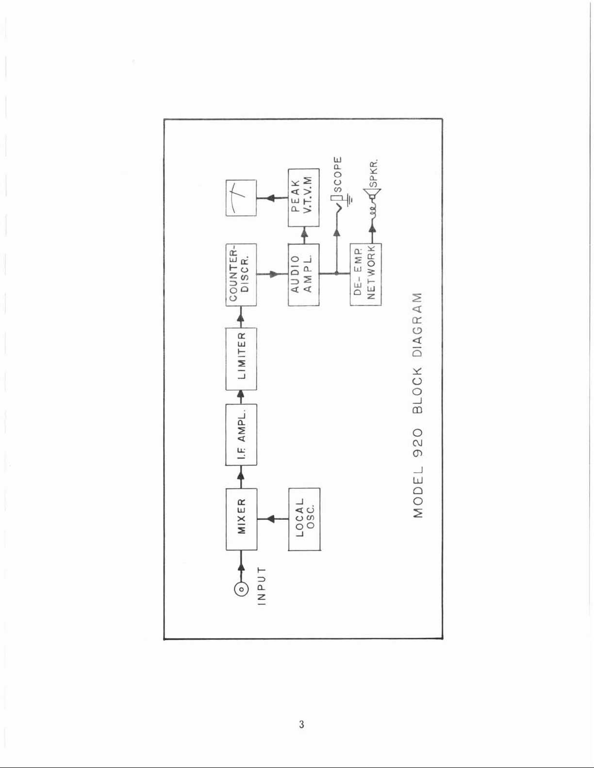
Block Diagram
of
Model
92
TABLE OF CONTENTS
PAGE
0
Section
Section
Section
Section IV POWER SUPPLY
I
I1
111
INTRODUCTION
A.
DESCRIPTION
A.
B.
C.
D.
E.
CONTROL
A.
B.
C.
Dm FineTuning
E.
F.
G.
H.
.
I
A.
B.
C. Battery Recharging Procedure
Scope of manual
General
Technical Characteristics
DesignFeatures
Components Supplied
Packaging
FUNCTIONS
Power
Input
Local Oscillator Tuning
Meter Range Switch
Audio Spkr
Audio Level
Scope
+
Battery Operation
A.
Gain
Deviation
C.
Operation
AND
Control
DATA
-
Section
Section
V
VI
OPERATION
A.
B.
C. Noise Measurements
MAINTENANCE
A.
B.
C. Removing the Instrument from the Case
Dm Distortion Adjust
Deviation Measurements
Distortion Measurements
General Precautions
Battery Installation
PAGE
E.
F.
G.
H.
I.
Section
VII STORAGE AND SHIPMENT
A.
B.
Section VIII
Section IX
APPENDIX I SCHEMATIC DIAGRAM
TABLE OF REPLACEABLE PARTS
PRINTED CIRCUIT BOARD PARTS LAYOUT
A.
B.
C. Pulse Network Board
D.
Em
Filter Termination Adjust
DividerAdjust
Meter Adjust
Discriminator Adjust
Power Overloads (Mixer CR4) Replacement
Storage
Shipment
Local Oscillator Board
I. F. Board
Audio Board
Filter and Power Supply Board
FOREWORD
Additional information with regard to the applications and
maintenance of this equipment will be available from time to time.
Users of the Model
their problems with us and to suggest such modifications as might make
the instrument more adaptable to their special requirements.
Whenever possible, maintenance difficulties should be reported to MEASUREMENTS before proceeding with the actual repairs.
Through our familiarity with the instrument, we are in
suggest the most expedient and accurate repair procedure.
920
Standard Deviation Meter are urged to discuss
a
position to
Your Model
and manufactured to the highest standards of instrument quality. With
reasonable care, many years of trouble-free service can be expected
it.
of
920
Standard Deviation Meter has been designed
Engineering Department
MEASURE
MENTS
AUTOMATED INDUSTRIAL ELECTRONICS CORP.
10
Granite Street
Batesburg,
S.
C.
29006

Figure
1.
Front View
of
the Model
920
Standard Deviation Meter
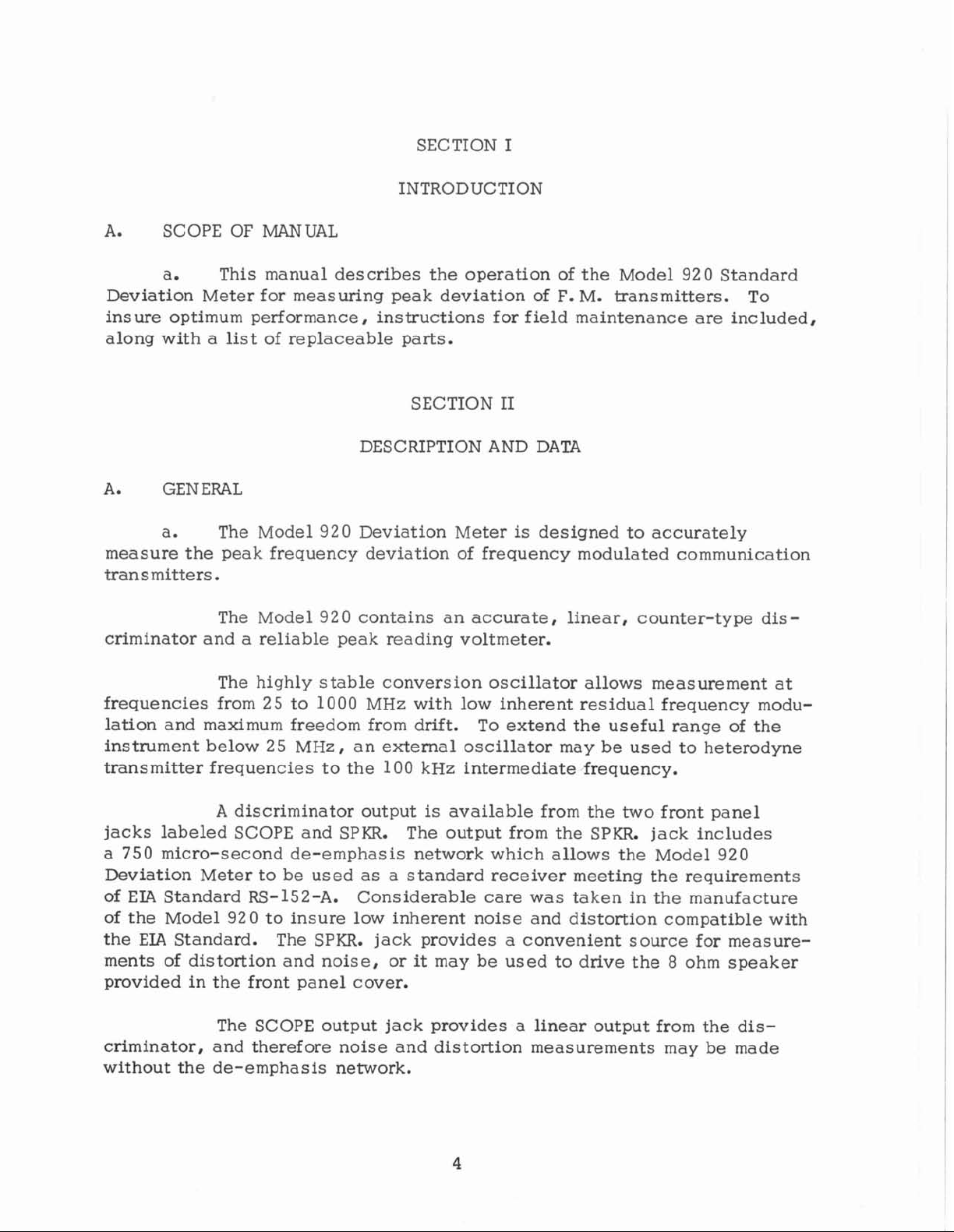
SECTION I
INTRODUCTION
A.
Deviation Meter for measuring peak deviation of
SCOPE OF
MANUAL
a. This manual describes the operation of the Model
F.
M.
transmitters. To
920
Standard
insure optimum performance, instructions for field maintenance are included,
along with a list of replaceable parts.
A.
GENERAL
a. The Model
SECTION
DESCRIPTION AND
920
Deviation Meter is designed to accurately
I1
DATA
measure the peak frequency deviation of frequency modulated communication
transmitters.
920
The Model
contains an accurate, linear, counter-type dis-
criminator and a reliable peak reading voltmeter.
The highly stable conversion oscillator allows measurement at
25
frequencies from
lation and maximum freedom from drift.
instrument below
to 1000 MHz with low inherent residual frequency modu-
To extend the useful range of the
25
MHz, an external oscillator may be used to heterodyne
transmitter frequencies to the 100 kHz intermediate frequency.
A
discriminator output is available from the two front panel
jacks labeled SCOPE and SPKR. The output from the
a 750 micro-second de-emphasis network which allows the Model
SPKR.
jack includes
920
Deviation Meter to be used as a standard receiver meeting the requirements
of
EIA
Standard RS-152-A. Considerable care was taken in the manufacture
of the Model
EIA
the
Standard.
ments of distortion and noise, or it may be used to drive the
92
0
to insure low inherent noise and distortion compatible with
The SPKR. jack provides a convenient source for measure-
8
ohm speaker
provided in the front panel cover.
The SCOPE output jack provides a linear output from the dis-
criminator, and
theref ore noise and distortion measurements may be made
without the de-emphasis network.
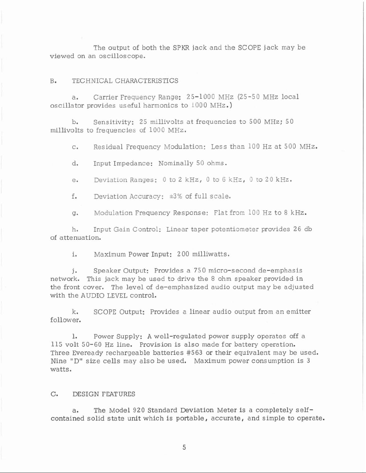
The output of both the SPKR jack and the SCOPE jack may be
viewed on an oscilloscope.
TECHNICAL CHARACTERISTICS
a. Carrier Frequency Range: 25-1000 MHz (25-50 MHz local
oscillator provides useful harmonics to
100
0
MHz.
)
be Sensitivity:
millivolts to frequencies of
c.
d. Input Impedance: Nominally 50 ohms.
e.
f.
g. Modulation frequency Response: Flat
h.
of attenuation.
i.
j.
network.
the front cover.
with the AUDIO
Residual Frequency Modulation:
geviation
Deviation Accuracy:
Input Gain Control: Li~ear taper potentiometer provides
Maximum Power Input: 2 00 milliwatt
Speaker Output: Provides a
This jack may be used to drive the
The level of de-emphasized audio output
LEVEL
Ranges:
control.
25
millivolts at frequencies to 500 MHz; 50
1000 MHz.
Less than 100 Hz at 500 MHz.
0
to
2
kHz,
*306
of full scale.
0 to
5
kzz,
froc
12
to
2
0
Hz
s.
75 0 micro-s econd de-emphasis
8
ohm speaker provided in
may be adjusted
kHz.
to 8 kHz.
26
db
k.
follower.
1
.
115 volt 50-60
Three
Nine "D" size
watts.
Ce
contained solid state unit which
Eveready rechargeable batteries
DESIGN FEATURES
a. The Model 920 Standard Deviation Meter
SCOPE Output: Provides a linear audio output from an emitter
Power Supply: A well-regulated power supply operates off a
Hz
line.
cells
Provision
may also be used.
is
also made for battery operation.
#563
is
portable, accurate, and simple to operate.
or their equivalent may be used.
Maximum power consumption
is
a
completely self-
is
3
b.
band panel meter.
Measurements are easily read on a large, linear,
taught-
c.
up to
dual noise.
batteries, (nominally 13. 5 volts) or from a
from the AC
supply provides good stability and low residual hum and noise.
up to their nominal voltage.
20 kHz are provided.
in the front cover.
emphasis network, and a level control.
output
1000 MHz.
d.
e.
f.
g.
h.
i,
is
An extremely stable local oscillator provides useful harmonics
This
oscill~i::,.r
For maximum portability the Model 920 may be powered from
When the Model
powzr line, a well-regulated and well-filtered
A
charging circuit
Three deviation ranges from
SPKR Output
SCOPE Output
linear and may be viewed on an oscilloscope,
is
provided along with an 8 ohm speaker mounted
The speaker output includes a 750 micro-second de-
is
is
completely shielded to minimize resi-
115
volt 50-60 Hz power line.
92
0 Standard Deviation Meter
is
provided to recharge rechargeable batteries
0 to 2 kHz, 0 to 6 kHz, and 0 to
available from a front panel jack. This
is
D.
operated
C. power
A
j.
deviation on both sides of the carrier.
D.
COMPONENTS SUPPLIED
a,
deviation
The following
1
Model 92 0 Standard Deviation Meter
Approx. Weight (less batteries)
1
Cover with speaker
1
Power Cord
1
Manual of Operating and Maintenance Instructions
1
Antenna
(+)
(-)
switch allows the measurement of peak
is
included with each shipment:
Height
Width
Depth 8-1/2"
Volume
10 lbs.
9"
7"
.
3
cu. ft.
 Loading...