

Page 1
Alarm Trigger Module
Connects to Sprinkler & EN54 Fire Systems (24V)
Instruction Manual
Contains vital information on the product’s operation and
installation. Read and retain carefully. If you are just installing
this product the manual MUST be given to the householder.
1. Introduction
The Ei129 is designed to sound interconnected Ei Electronics
Mains Powered Alarms to give a fire warning. When the
external normally open contacts connected to it, close.
Its main applications are:
1. To trigger the Smoke/Heat/Fire Alarms to sound when a
Sprinkler System is activated.
2. To trigger all the Smoke/Heat/Fire Alarms in an apartment
to sound when the EN54 Fire System in the common areas
of the HMO* sense fire. This greatly increases the alarm
sound level throughout the apartment (this helps meet the
recommendations of the BS5839-6: 2004 Clause 13.2e)
which requires 85dB(A) at each bedroom doorway. (It can
also help meet the recommendations of Clause 13.2f) of
75dB(A) at each bed head where the fire risk assessment
warrants it).
* HMO - House in Multiple Occupancy
2. Installation Instruction
2.1 Installation of Ei129 under Ei Electronics Easi-Fit Alarms.
WARNING: Mains powered Alarm Trigger Modules should be
installed by a qualified electrician in accordance with the
regulations for Electrical Installations published by the
Institution of Electrical Engineers (UK) (i.e. BS7671). Failure
to install the unit correctly may expose the user to shock or fire
hazards. This unit is not waterproof and must not be exposed
to dripping or splashing.
WARNING: First disconnect the mains from the circuit to be
used.
2.1.1 Choose a mounting position following the siting
instructions in the Smoke/Heat/Fire Alarm leaflet. Bring the
wiring from the external N/O contacts to this position. (With
an EN54 System an Input/Output Module is required and with
a Sprinkler System Changeover contacts should be specified
when it is being installed).
1
Model: Ei129
230V~ with
Battery Backup
A16697-R0-Ei129-UC-ENG 28/7/09 2:30 PM Page 1
Page 2
Caution:
The N/O contacts in the external device connected to the
Ei129, must be electrically isolated and rated for 230V~.
2.1.2 Where the incoming wiring is on the surface of the
ceiling, the appropriately sized ducting/conduit must be
chosen to mate with the unit. Use a sharp knife to remove
material from the selected knockout, making sure there is no
gap when mated with ducting / conduit. There are three
knockouts – two on the sidewall and one on the rear. (Do no
use the knockout next to the circuit board as the wiring may
damage the components).
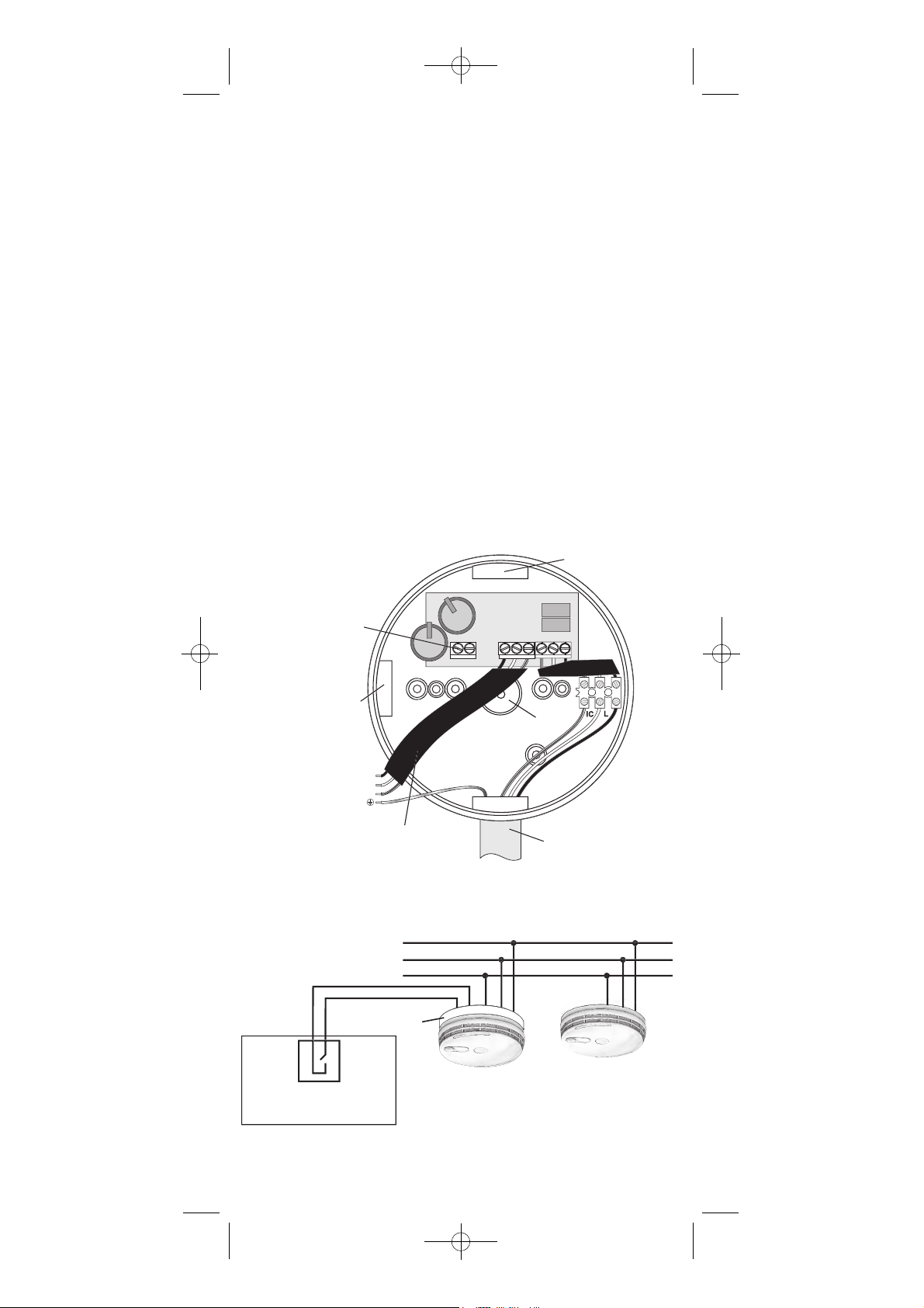
2.1.3 Screw the Ei129 Module to the ceiling after first
removing the required knockout and bring the house wires
through it (see Figure 1). If the contact knockout is being
used, seal around the wires with silicone or similar to prevent
air draughts affecting the smoke or heat entering the alarm.
2.1.4 Connect the wires from the alarms (L – Live, N –
Neutral, and IC – Interconnect) to the terminal block on the
Ei129 Module as shown in Figure 1. Make the wiring
connections as shown in Figure 2.
SU
CE
CONDUIT
S
CO
O
R
CO
S
CO
T
SMO
M
S
CT
L
O
G
OCKOUT
Figure 1- Ei129 Model
Figure 2
2
S
m
s
e
ct
al
9
A16697-R0-Ei129-UC-ENG 28/7/09 2:30 PM Page 2
NNECT T
TRIGGE
NTACT
CONTACTS IN
(DON'T USE THI
KNOCKOUT)
IC LN
NNECT TO EASI-FI
KE / HEAT / FIRE ALAR
MOUNTING PLATE TERMINAL
IC - INTERCONNE
EARTH - (IF PRESENT)
prinkler or EN54 Fire Syste
N/O Contact
(Electricly Isolated & rated 230V~)
KN
-
N - NEUTRA
REM
AN EASI-FIT ALARM ON
TOP OF BASE AND USING
AN Ei128COV COVER
IC-Interconne
-Neutr
VE IF NOT FITTIN
L-Liv
Ei12
KNOCKOUT
RFA
CABLE
ENTRY
i161RC/164RC/166RC
41/144/146/2110 Alarm
Page 3

2.1.5 Connect the two wires from the external N/O contacts to
the “Contacts In” terminals.
2.1.6 Connect the three short wires (“L” Brown, “N” Blue and
“IC White) from the Ei129 Module to the connector block on
the Smoke/Heat/Fire Alarm Easi-Fit Mounting Plate. Connect
the earth wire (if present) from the house wiring directly to the
terminal on the Easi-Fit Mounting Plate (see relevant
Smoke/Heat/Fire Alarm instructions). Replace the cover over
the terminal wires on the mounting plate.
2.1.7 Screw the Mounting Plate to the Ei129 Module Base
pillars using the two screws supplied.
2.1.8 Slide the alarm on to the mounting plate.
2.1.9 Re-Connect the mains power – the green LED on the
alarm should be on. Check the alarms as per their instruction
manuals by pressing the test buttons.
NOTE: A maximum of 12 Smoke/Heat/Fire Alarms of the
types specified may be interconnected to one or more Ei129
Alarm Trigger Modules.
2.1.10 Trigger the external contacts (e.g. at the Sprinkler
System Control Panel or the EN54 Fire System Panel) and
check that all the Smoke / Heat / Fire Alarms sound.
2.2 Installation of Ei129 with Cover Plate Ei128COV
2.2.1 If it is not convenient to install the Ei129 Module under
an alarm and / or it is preferable to mount it near the external
contacts then it can be installed as described above on a
suitable wall or ceiling. An Ei128COV Cover Plate is needed
which must be purchased separately.
2.2.2 Connect the wires from the alarms (L – Live, N –
Neutral, and IC – Interconnect) to the terminal block on the
Ei129 Module as shown in Figure 1. Then connect the two
wires from the external N/O contacts to the “CONTACTS IN “
terminals.
2.2.3 Important: Now remove the three short sleeved wires
from the central terminal block on the circuit board on the
Ei129 as they are now not needed (see figure 1). This is
essential to prevent them shorting and damaging the alarms
or blowing fuses.
3
Figure 3
m
s
e
ct
al
A16697-R0-Ei129-UC-ENG 28/7/09 2:30 PM Page 3
L-Liv
IC-Interconne
-Neutr
prinkler or EN54 Fire Syste
N/O Contact
(Electricly Isolated & rated 230V~)
Ei129 with Cover Plate
Ei128COV
Ei161RC/164RC/166RC
141/144/146/2110 Alarm
Page 4

2.2.4 Screw the Ei128COV Cover Plate to the Ei129 Module
using the two screws supplied.
2.2.5 Now follow the instructions from 2.1.9 and 2.1.10 above
and check the system is operation correctly.
3. Checking and Maintaining Your Fire Alarm
System
3.1.1 We recommend a weekly check is made of your Alarm
System as described in the Smoke/Heat/Fire alarm
instructions. When checking the system also check the green
light is lit on the nearest alarm to the Ei129 module.
3.1.2 When the external system is being routinely checked
(e.g. the Sprinkler System or the EN54 Fire Alarm 24V
System), the contacts connected to the Ei129 Module should
be operated. Check that all the alarms connected to the
Ei129 Module, sound.
3.2 Checking the Back-Up Lithium Cells in the Ei129
It is important to check that the rechargeable cells in the Ei129
Module are charged and capable of triggering all the alarms
to sound. This should be done after installation and then at
least annually (when Smoke/Heat Alarms rechargeable cells
are being checked0.
3.2.1. Disconnect the mains supply. Trigger the Ei129 Module
as described in 3.1.2 above. Check all the alarms sound
loudly. If everything is satisfactory, re-connect the mains.
3.3 End of Life
After 10 years, or if it fails to operate and the fault has been
traced to the Ei129, it is defective and must be replaced. (See
the ‘replace by’ label on the side of the Ei129 Module base).
4. Getting your Alarm Trigger Module serviced
If you Ei129 Module fails to work after you have carefully read
all the instructions, checked that the unit has been installed
correctly, and is receiving AC power, then contact Customer
Assistance at the nearest address given at the end of this
leaflet. If it needs to be returned for repair or replacement,
remove the unit. Put the Ei129 Module in a padded box and
send it to “Customer Assistance And Information” at the
nearest address given on the unit or in this leaflet. State the
nature of the fault, where the Base was purchased and date
of purchase.
5. Five Year Guarantee
Ei Electronics, guarantees the Ei129 Module for five years
from date of purchase against any defects that are due to
faulty materials or workmanship. This guarantee only applies
to normal conditions of use and service, and does not include
damage resulting from accident, neglect, misuse,
unauthorised dismantling, or contamination howsoever
4
A16697-R0-Ei129-UC-ENG 28/7/09 2:30 PM Page 4
Page 5

caused. This guarantee does not cover costs associated with
the removal and/or installation of units. If this Module should
become defective within the guarantee period, it must be
returned to with proof of purchase, carefully packaged, and
with the problem clearly stated to one of the addresses
detailed below (see “Getting your Alarm Trigger Module
serviced”). We shall at our discretion repair or replace the
faulty unit.
Do not interfere with the Module or attempt to tamper with it.
This will invalidate the guarantee, but more importantly may
expose the user to shock or fire hazards. This guarantee is in
addition to your statutory rights as a consumer.
Aico Ltd
Mile End Business Park,
Maesbury Road, Oswestry, Shropshire SY10 8NN, U.K.
Telephone: 0870 7584000
www.aico.co.uk
Ei Electronics
Shannon Industrial Estate,
Shannon, Co. Clare, Ireland.
www.eielectronics.com
5
The crossed out wheelie bin symbol that is on your
product indicates that this product should not be disposed
of via the normal household waste stream. Proper
disposal will prevent possible harm to the environment or
to human health. When disposing of this product please
separate it from other waste streams to ensure that it can
be recycled in an environmentally sound manner. For
more details on collection and proper disposal, please
contact your local government office or the retailer where
you purchased this product.
A16697-R0-Ei129-UC-ENG 28/7/09 2:30 PM Page 5
Page 6

Technical Specifications
Supply Voltage: 230V AC, 50Hz, 25mA, 0.5W.
Battery Back-Up: Rechargeable Lithium Cells.
Standby back-up will last up to 12 months.
Alarm Back-up will last up to 20 Hours.
Alarm Connection: Up to 12 Ei2110/Ei141/Ei144/Ei146
Ei161RC/Ei164RC/Ei166RC/Ei261ENRC
Smoke/Heat/Fire/CO Alarms can be
connected to one or more Ei129 modules
Trigger Input: Normally Open Contacts that are 230VAC
mains rated and electronically isolated.
(EN54 Fire Systems, 24V, normally
require Input/Output Units such as
Hochiki CHQ- MRC-Mains Relay
Controller or Apollo XP95 Mains
Isolated Input/Output Unit.
Fixing: Mounts directly under any Ei140, Ei160RC
or Ei2110 series alarm. Alternatively can
be remotely sited when used with an
Ei128COV Cover Plate
(Purchased Separately).
Temperature
Range: 0
0
C to 400C
Humidity Range: 0% to 95% R.H.
Dimensions: 141mm (dia) x 25mm (height)
Weight: 160g
Guarantee: 5 year (limited)
Electrical Safety: Complies with BSEN60065: 2002
(Tested by BSI)
Approvals: CE Marked
6
© Ei Electronics 2009P/N A16697 Rev0
A16697-R0-Ei129-UC-ENG 28/7/09 2:30 PM Page 6
 Loading...