

Page 1
RELAY BASES & COVERS
FOR SMOKE, HEAT & CARBON MONOXIDE ALARMS
Common Instruction Manual
Contains vital information on the product’s operation and
installation. Read and retain carefully. If you are just installing
this product the manual MUST be given to the householder.
1. Description of Models & Usage
Ei128R - Relay Base with remote terminal. Relay Output
250VAC / 5 Amps. Normally used directly
underneath Easi-fit Smoke & Heat Alarms. When
used with accessory cover Ei128COV the
combination may be sited at the fuse box or
other suitable locations. The combination can
also be used with other Ei Smoke, Heat &
Carbon Monoxide Alarms - see section 3.
Ei128RBU - Same as the Ei128R above but with the addition
of a rechargeable cell backup.
Ei128COV - Plastic cover for use with Ei128R & Ei128RBU
Relay Bases when they are not sited underneath
the actual alarms they are serving.
2. Ei128R & Ei128RBU Instructions
2.1 Introduction
The Ei128R & Ei128RBU Relay Bases switch a relay upon
receipt of an alarm signal from a suitable Ei Smoke, Heat or
Carbon Monoxide Alarm. The electrically isolated contacts
can be used for many applications such as signalling, turning
on lights, etc. The Relay Bases are powered by 230VAC
mains - with the Ei128RBU model having recharbeagle backup cells.
As supplied the relay operates continuously (e.g. it switches
when one of the Smoke / Heat Alarms detects fire and
switches back when the smoke clears).When the slide switch
is moved to the pulse ‘P’ position (see figures 1 & 2) the relay
will switch when fire is detected but will automatically switch
back after 5 seconds. This is commonly used with warden call
systems where only momentary short circuit signalling is
required.
2.2 Installation under Easifit Smoke / Heat Alarms
WARNING: Mains powered Relay Bases should be installed
by a qualified electrician in accordance with the Regulations
for Electrical Installations published by the Institution of
Electrical Engineers (UK) (i.e. BS7671). Failure to install the
1
Ei128R
Ei128RBU
Ei128COV
Models:
A15420-R1-Ei128RBU-UC-ENG 9/1/08 10:56 AM Page 1
Page 2
unit correctly may expose the user to shock or fire hazards.
This unit is not waterproof and must not be exposed to
dripping or splashing.
WARNING: First disconnect the mains from the circuit to be used.
1. Choose a mounting position following the siting instructions
in the Smoke/Heat Alarm leaflet. Where the incoming wiring
is on the surface of the ceiling, the appropriately sized
ducting/conduit must be chosen to mate with the unit. Use a
sharp knife to remove material from the selected knockout,
making sure that there is no gap when mated with ducting /
conduit. There are three knockouts – two on the sidewall and
one on the rear.
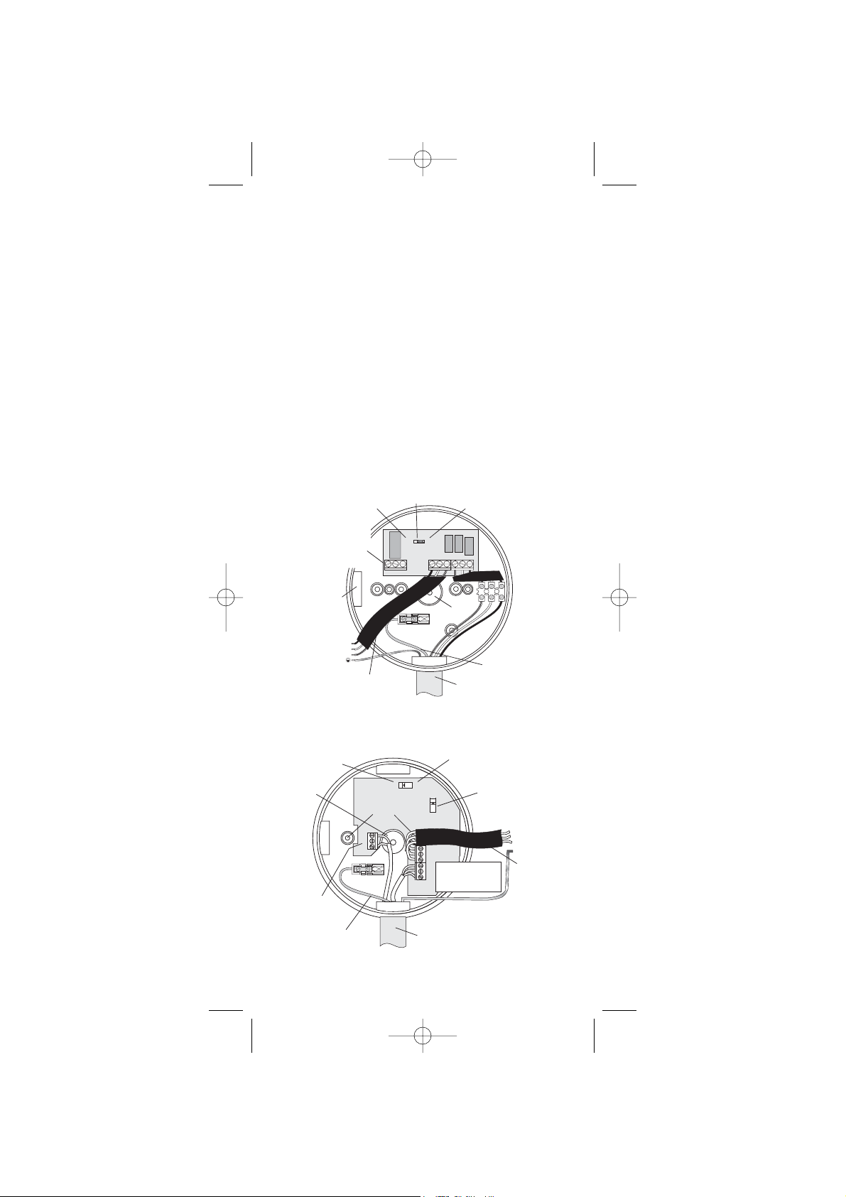
2. Screw the Relay Base to the ceiling after first removing the
required knockout and bringing the house wires through it
(see figure 1a for Ei128R & figure 1b for Ei128RBU). If the
central knockout is being used, seal around the wires with
silicone or similar to prevent air draughts affecting the smoke
entering the alarm.
Figure 1b - E128RBU Model
Figure 1a - E128R Model
2
A15420-R1-Ei128RBU-UC-ENG 9/1/08 10:56 AM Page 2
CONNECT RELAY
WIRES TO THE
TERMINAL BLOCK
NO - NORMALLY OPEN
NC - NORMALLY CLOSED
C - COMMON
(DOUBLE INSULATE ALL WIRES)
MOUNTING PLATE TERMINALS
KNOCKOUT
CONNECT TO EASI-FIT
SMOKE / HEAT ALARM
IC - INTERCONNECT
N - NEUTRAL
EARTH - (IF PRESENT)
RELAY CHANGES
FOR 5 SECONDS
L - LIVE
REMOVE IF NOT FITTING
AN EASI-FIT ALARM ON
TOP OF BASE
SLIDE SWITCH
OFF ON
NCC
NO
R
CONTINUOUS RELAY
ICICLLN
KNOCKOUT
SURFACE
CONDUIT
CABLE
ENTRY
N
FOR Ei161R/164R/166R
REMOTE CONTROL ONLY
REAR ENTRY
KNOCKOUT
SURFACE
CONDUIT
CABLE
ENTRY
CONNECT RELAY
WIRES TO THE
TERMINAL BLOCK
NO - NORMALLY OPEN
NC - NORMALLY CLOSED
C - COMMON
(DOUBLE INSULATE ALL WIRES)
FOR Ei161R/164R/166R
REMOTE CONTROL ONLY
P - PULSE
RELAY CHANGES
FOR 5 SECONDS
SCREW
MOUNTING
HOLES
NO
NC
C
R
P
C - CONTINUOUS RELAY
C
ON
OFF
N
IC
L
L
CONNECT MAINS
IC
TO TERMINAL BLOCK
L - LIVE
N
N - NEUTRAL
IC - INTERCONNECT
SURFACE
CONDUIT
CABLE
ENTRY
RECHARGEABLE
CELLS
ON/OFF
SLIDE SWITCH
CONNECT TO EASI-FIT SMOKE / HEAT ALARM
MOUNTING PLATE TERMINALS
N - NEUTRAL
IC - INTERCONNECT
L - LIVE
EARTH IF PRESENT
REMOVE IF NOT FITTING
AN EASI-FIT ALARM ON
TOP OF BASE
Page 3

3. Connect the house wires (L - Live, N - Neutral and IC Interconnect, (if it is being used)) to the terminal block on the
Relay Base. If an Ei161R, Ei164R or Ei166R Smoke Alarm is
being used with an Ei152 Control Switch or an
MCP400/MCP401 Manual Call Point, attach the “R” wire from
the Ei152 or the MCP400/MCP401 to the terminal marked “R”
in the Relay Base (see figure 1a & 1b).
If an Ei152 Control Switch and an MCP400/MCP401 Manual
Call Point are being used on the same circuit (see figure 2),
attach both “R” wires to the terminal marked “R” in the Relay
Base. Otherwise do not connect anything to the ”R” terminal.
4. Connect the three wires (“L”, “N” and “IC”) from the Relay
Base to the connectors on the Smoke/Heat Alarms mounting
plate. This “IC” wire must be connected even if it is a single
alarm installation. Connect the earth wire (if present) from the
house wiring directly to the terminal on the mounting plate
(see relevant Smoke Alarm Instructions). Replace the cover
over the terminal wires.
Connect the wires to the required relay contacts for controlling
the auxiliary device (the contacts are isolated and are rated at
250VAC, 5 Amps resistive).
5. Connect the rechargeable cells (Ei128RBU only) by
carefully and gently sliding the switch to the “on” position (see
figure 1b). This switch must be in the ‘on’ position to ensure
correct operation.
6. Screw the mounting plate to the Relay Base pillars using
the two screws supplied.
7. Slide the alarm on to the mounting plate.
8. Re-connect the mains power – the green LED light on the
alarm should be on. When the test button is pressed the horn
should sound and the relay will switch within 10 seconds.
(Note - with ionisation alarms the relay normally switches 4
seconds after the horn sounds. With optical alarms the relay
normally switches within 2 seconds of the horn sounding).
Note: A maximum of 12 Smoke/Heat Alarm of the types
specified may be interconnected to one Relay Base. When
one alarm senses fire all interconnected units will alarm and
the relay will switch.
3. Checking & Maintaining Your Smoke Alarm System
We recommend a weekly check is made of your alarm system.
When checking the system also check the Relay Base as follows:
Figure 2
3
A15420-R1-Ei128RBU-UC-ENG 9/1/08 10:56 AM Page 3
Ei128RBU
or
Ei128R
Page 4

1.Check the green mains light is lit on the Smoke Alarm that
is electrically connected to the Relay Base.
2.Check the relay switches and that the associated device
operates when the system is in alarm (e.g. due to a smoke
alarm test button being pressed).
3. On the Ei128RBU only the rechargeable cells are capable
of powering the relay for up to 2 months in the event of the
mains being off.
4. Checking Relay Back-Up Cells
Model Ei128RBU only
It is important to check that the rechargeable cells in the
Ei128RBU Relay Base are switched on, charged and capable
of powering the system. This should be done after installation
and then at least annually.
(i) Disconnect the mains supply. Check the relay as described
in section 3 above.
(ii) If everything is satisfactory, re-connect the mains.
If the relay fails to operate then the unit is defective and must
be replaced (see getting your Relay Base Serviced as per
section 5 below).
End of Life
After 10 years (see date label on the side of the Relay Base)
the Ei128RBU Relay Base must be replaced.
5. Installation away from the alarm
5.1 Introduction
Whenever there is a need to install the Relay Base at
locations other than underneath the Easi-fit alarms then an
Ei128COV is required. This is to ensure that the user is not
exposed to fire or shock hazards.
Note that in addition to the Ei Easi-fit Alarms, other Ei devices can
be connected to the Relay Bases. The Ei mains range of Smoke
& Heat Alarms Ei150 Series and the interconnectable Carbon
Monoxide Alarms Ei261EN & Ei261DEN can be connected to
trigger the Relay.
Warning: The Relay Bases must not be used with any other
devices - otherwise they would not comply with the mandatory
safety regulations.
5.2 Installation
The installation of the Relay Bases themselves is covered in
section 2 previously.
WARNING: Mains powered Carbon Monoxide / Smoke / Heat
Alarms should be installed by a qualified electrician in
accordance with the Building Regulations for Electrical
Installations published by the Institution of Electrical
Engineers (UK). Failure to install the unit correctly may
expose the user to shock or fire hazards.
Warning: First disconnect the mains from the circuit to be used.
4
A15420-R1-Ei128RBU-UC-ENG 9/1/08 10:56 AM Page 4
Page 5

1. Install the Carbon Monoxide / Smoke / Heat Alarm as
described in the leaflet supplied with the unit. The Relay
Module can be located near the fuse box or in some other
location convenient to the Carbon Monoxide / Smoke / Heat
Alarm wiring. Where the incoming wiring is on the surface of
the ceiling, the appropriately sized ducting/conduit must be
chosen to mate with the unit. Use a sharp knife to remove to
material from the selected knockout, making sure that there is
no gap when mated with ducting / conduit. There are three
knockouts – two on the sidewall and one on the rear.
2. Screw the Relay Base to the ceiling after first removing the
required knockout and bringing the house wires through it
(see figures 1a & 1b).
3. Connect the three wires (L - Live, N - Neutral and IC Interconnect) from the Carbon Monoxide / Smoke / Heat
Alarm to the alarm relay module as shown in figures 1a & 1b.
The IC - Interconnect wire must be connected even if it is a
single alarm installation.
As an Easi-fit Alarm is not being mounted on top of the Relay
Base, remove the three cables (for the Easi-fit Alarm connection)
from the terminal block and discard (see figures 1a & 1b).
Connect the wires to the required relay contacts for controlling
the auxiliary device (the contacts are isolated and are rated at
250VAC, 5 Amps resistive). If momentary (pulse) relay
operation is required, carefully and gently slide the yellow
switch to the ‘off’ (Ei128R) or ‘P’ (Ei128RBU) position with a
small screwdriver (see figures 1a & 1b).
4. Screw the cover plate to the Relay Module using the two
screws supplied.
5. Connect the mains power – the green LED light on the
alarm should be on. When the test button is pressed the horn
should sound and the relay will switch within 10 seconds.
With some alarms it may take up to 5 seconds for the relay to
switch after the horn has sounded.
Note 1: A maximum of 12 Carbon Monoxide Alarms or 12
Smoke Alarm of the types specified may be interconnected to
one Relay Base. When one unit alarms all interconnected
units will alarm and the relay will switch.
Figure 4
5
A15420-R1-Ei128RBU-UC-ENG 9/1/08 10:56 AM Page 5
Ei261DEN
The above shows the connection for Carbon Monoxide Alarms.
Connect the Smoke/Heat Alarm similarly but on a seperate circuit to the
Carbon Monoxide Alarm (unless an Ei159 Locator Switch is used on the system)
Ei261D/
Ei261/
Ei261EN
Ei128R / Ei128RBU
& Ei128COV
Page 6

Warning: Do not connect Carbon Monoxide Alarms and
Smoke / Heat Alarms on the same system without using an
Ei159 Locator Switch. The Ei159 Locator Switch will allow the
user to identify the source of the alarm (e.g. smoke or CO
gas). This is important because if the Carbon Monoxide Alarm
triggers the user must ventilate the premises. If the Smoke
Alarm triggers the user should close doors to slow down the
spread of fire.
Note 2: An alarm with battery back-up will continue to operate
during a mains failure but will not be able to switch the Ei128R
relay (the relay requires the 230 VAC to operate). However the
Ei128RBU relay will be able to switch during mains failure
because of its back-up cells.
Note 3: Devices connected to the relay contacts do not give a
warning until the contacts have switched for at least 200mSec.
6. Getting your Relay Base Serviced
If your Relay fails to work after your have carefully read all the
instructions, checked that the unit has been installed correctly,
and is receiving AC power, then contact Customer Assistance
at the nearest address given at the end of this leaflet. If it
needs to be returned for repair or replacement, remove the unit
and turn off the rechargeable cells with slide switch (see
Figure1b). Put the Relay in a padded box and send it to
“Customer Assistance and Information” at the nearest address
given on the unit or in this leaflet. State the nature of the fault,
where the Base was purchased and date of purchase.
7. Five Year Guarantee
Ei Electronics, guarantees the Relay Bases for five years from date of
purchase against any defects that are due to faulty materials or
workmanship. This guarantee only applies to normal conditions of use and
service, and does not include damage resulting from accident, neglect,
misuse, unauthorised dismantling, or contamination howsoever caused.
This guarantee does not cover costs associated with the removal and/or
installation of units. If this Relay Base should become defective within the
guarantee period, it must be returned to with proof of purchase, carefully
packaged, and with the problem clearly stated to one of the addresses
detailed below (see “Getting Your Relay Base Serviced”). We shall at our
discretion repair or replace the faulty unit.
Do not interfere with the Relay Base or attempt to tamper with it. This will
invalidate the guarantee, but more importantly may expose the user to
shock or fire hazards. This guarantee is in addition to your statutory rights
as a consumer.
Aico Ltd. Mile End Business Park,
Maesbury Road, Oswestry, Shropshire SY10 8NN, U.K.
Telephone: 0870 7584000 www.aico.co.uk
Ei Electronics. Shannon Industrial Estate,
Shannon, Co. Clare, Ireland. www.eielectronics.com
6
© Ei Electronics 2006P/N A15420 Rev1
A15420-R1-Ei128RBU-UC-ENG 9/1/08 10:56 AM Page 6
The crossed out wheelie bin symbol that is on your
product indicates that this product should not be disposed
of via the normal household waste stream. Proper
disposal will prevent possible harm to the environment or
to human health. When disposing of this product please
separate it from other waste streams to ensure that it can
be recycled in an environmentally sound manner. For
more details on collection and proper disposal, please
contact your local government office or the retailer where
you purchased this product.
 Loading...