

AIC Vela User Manual

Vela
Server Motherboard
User's Manual
UM_Vela_v1.1_110419

Table of Contents
Preface ��������������������������������������������������������������������������������������������������������� i
Safety Instructions ��������������������������������������������������������������������������������������ii
About This Manual �������������������������������������������������������������������������������������� iii
Chapter 1� Product Features ����������������������������������������������������������������������1
1�1 Component ���������������������������������������������������������������������������������������1
1.2 Specications ����������������������������������������������������������������������������������� 2
1�3 Feature ���������������������������������������������������������������������������������������������3
Chapter 2� Hardware Setup ������������������������������������������������������������������������4
2�1 Central Processiong Unit Setup ���������������������������������������������������������4
2.1.1 Processor Support ..............................................................................................4
2.1.2 Processor Heat Sink Module and Processor Socket Assembly .......................5
2.1.3 Processor Heat Sink Module ..............................................................................6
2�2 System Memory ��������������������������������������������������������������������������������8
2.2.1 Placement ...........................................................................................................8
2.2.2 DIMM Population ...............................................................................................9
2.2.3 DCPMM DIMM Population ............................................................................. 11
2.2.4 Installation ....................................................................................................... 12
Chapter 3� Motherboard Settings ������������������������������������������������������������� 13
3�1 Block Diagram ��������������������������������������������������������������������������������13
3�2 Content List ������������������������������������������������������������������������������������ 14
3�3 Placement ��������������������������������������������������������������������������������������15
3�4 Connector and Jumper �������������������������������������������������������������������� 16
3.4.1 Connector ......................................................................................................... 16
3.4.2 Jumper ............................................................................................................. 19
3�5 LED Indicator ����������������������������������������������������������������������������������20
Chapter 4. BIOS Conguration Settings ���������������������������������������������������21
4�1 Navigation Keys ������������������������������������������������������������������������������ 21
4�2 BIOS Setup �������������������������������������������������������������������������������������22
4.2.1 Menu ................................................................................................................. 22
4.2.2 Startup .............................................................................................................. 22
4.2.3 Update .............................................................................................................. 24
4.2.4 DCPMM Setup .................................................................................................. 26
4�3 Main ����������������������������������������������������������������������������������������������31
4.3.1 Main .................................................................................................................. 31
4�4 Advanced ���������������������������������������������������������������������������������������� 32
4.4.1 Platform Information ....................................................................................... 32
4.4.2 Boot Conguration .......................................................................................... 32
4.4.3 Peripheral Conguration ................................................................................. 32
4.4.4 Video Conguration ......................................................................................... 33
4.4.5 ACPI Table/Features Control ........................................................................... 33
4.4.6 System Event Log ............................................................................................ 33
4.4.7 Debug Conguration........................................................................................ 35
4.4.8 OEMBoard Function ......................................................................................... 35
Content

4.4.9 SIO AST2500 .................................................................................................... 36
4.4.10 Socket Conguration ..................................................................................... 36
4.4.11 ME Conguration ........................................................................................... 40
4.4.12 PCH Conguration ......................................................................................... 41
4.4.13 H2O IPMI Conguration ................................................................................ 44
4.4.14 APEI Conguration ........................................................................................ 44
4.4.15 H2O Event Log Cong Manager .................................................................... 44
4.4.16 H2oUve Conguration ................................................................................... 44
4.4.17 Console Redirection ...................................................................................... 45
4�5 Security ������������������������������������������������������������������������������������������46
4.5.1 Security ............................................................................................................ 46
4�6 Power ���������������������������������������������������������������������������������������������47
4.6.1 Power ............................................................................................................... 47
4�7 Boot ������������������������������������������������������������������������������������������������48
4.7.1 Boot .................................................................................................................. 48
4�8 Exit �������������������������������������������������������������������������������������������������49
4.8.1 Exit .................................................................................................................... 49
Chapter 5. BMC Conguration Settings ����������������������������������������������������50
5�1 Login ����������������������������������������������������������������������������������������������50
5�2 Web GUI ���������������������������������������������������������������������������������������� 51
5.2.1 Menu Bar .......................................................................................................... 51
5.2.2 User Information and Quick Button ............................................................... 52
5.2.3 Dashboard ........................................................................................................ 53
5.2.4 Sensor .............................................................................................................. 53
5.2.5 FRU Information ............................................................................................... 54
5.2.6 Logs and Reports ............................................................................................ 54
5.2.7 Settings ............................................................................................................ 55
5.2.8 Remote Control ................................................................................................ 56
5.2.9 Power Control .................................................................................................. 60
5.2.10 Maintenance .................................................................................................. 61
5.2.11 Sign out .......................................................................................................... 62
5�3 Firmware Update �����������������������������������������������������������������������������63
Chapter 6� Technical Support ������������������������������������������������������������������� 64
Content

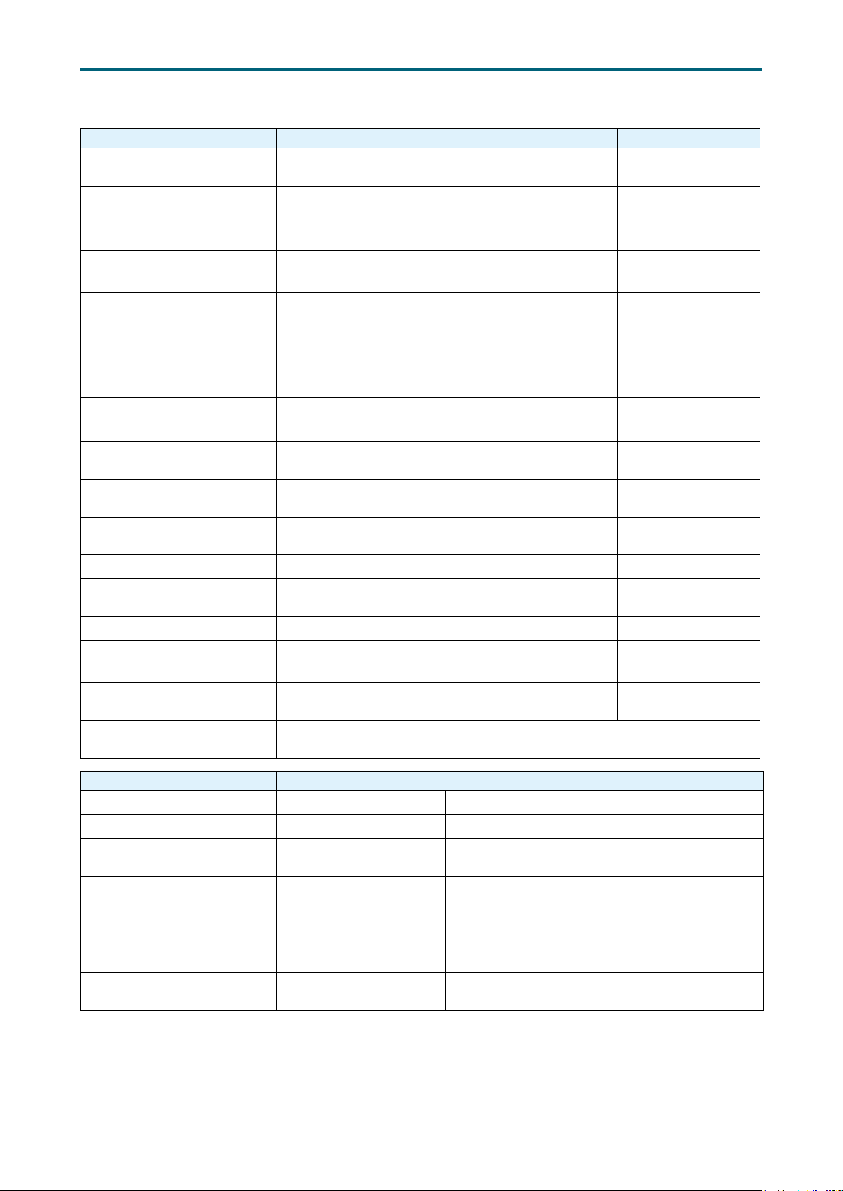
Document Release History
Release Date Version Update Content
September
2019
1 User's Manual release to public.
November
2019
1.1 Specication update.

Copyright © 2019 AIC, Inc� All Rights Reserved�
This document contains proprietary information about
AIC products and is not to be disclosed or used except in
accordance with applicable agreements.

Preface
Copyright
No part of this publication may be reproduced, stored in a retrieval system, or
transmitted in any form or by any means, electronic, mechanical, photo-static, recording
or otherwise, without the prior written consent of the manufacturer.
Trademarks
All products and trade names used in this document are trademarks or registered
trademarks of their respective holders.
Changes
The material in this document is for information purposes only and is subject to change
without notice.
Warning
1. A shielded-type power cord is required in order to meet FCC emission limits and also
to prevent interference to the nearby radio and television reception. It is essential
that only the supplied power cord be used.
2. Use only shielded cables to connect I/O devices to this equipment.
3. You are cautioned that changes or modifications not expressly approved by the
party responsible for compliance could void your authority to operate the equipment.
Disclaimer
AIC shall not be liable for technical or editorial errors or omissions contained herein.
The information provided is provided "as is" without warranty of any kind. To the
extent permitted by law, neither AIC or its afliates, subcontractors or suppliers will be
liable for incidental, special or consequential damages including downtime cost; lost
profits; damages relating to the procurement of substitute products or services; or
damages for loss of data, or software restoration. The information in this document
is subject to change without notice.
Instruction Symbols
Special attention should be given to the instruction symbols below.
NOTE
CAUTION
WARNING
This symbol indicates that there is an explanatory or
supplementary instruction.
This symbol denotes possible hardware impairment. Upmost
precaution must be taken to prevent serious harware damage.
This symbol serves as a warning alert for potential body
injury. The user may suffer possible injury from disregard or
lack of attention.
i

Safety Instructions
When installing, operating, or performing maintenance on this equipment, the following
safety precautions should always be taken into account in order to reduce the risk of fire,
electric shock, and personal injury.
Carefully read the safety instructions below before using this product.
• Observe all of the warning and instruction signs distinctively marked on the product.
• Before performing system installations, please consult the User’s Manual provided
with this product.
• Do not place this product on an uneven or weak surface (unstable cart, stand, table,
ect.) that might induce the product to fall and sustain serious damage.
• Install only the equipment or device identified in the User’s Manual. Deploying other
equipment or device with this motherboard could invoke improper connection of
circuitry that leads to fire or personal injury.
• This product should only be operated with the type of power source indicated on the
marked label. If you are questionable about which type of power supply is used in your
area, consult your dealer or local Power Company.
• Disconnect the power supply module before removing power from the system.
• Unplug this product from the wall outlet before cleaning. Use a damp cloth for
cleaning. Do not use liquid cleaners or aerosol cleaners.
• Do not use this product near a water source, including faucet and lavatory.
• Never spill liquids of any kind on this product.
• Never shove objects of any kind into this product’s open slots, as they may touch
dangerous voltage points or short out parts and could result in fire or electric shock.
• Do not block or cover slots and openings in this unit, as they were made for ventilation
and prevent this unit from overheating. Do not place this product in a built-in
installation unless proper ventilation is available.
• Do not disassemble this product. This product should only be taken apart by trained
personnel. Opening or removing covers and circuit boards may expose you to electric
shock or other risks. Incorrect reassembly can also cause electric shock when the
unit is subsequently used.
• Risk of explosion is possible if battery is replaced with an incompatible type. Dispose
of used batteries accordingly.
• This product is equipped with a three-wire grounding type plug, a plug with a third
(grounding) pin. As a safety feature, this plug is intended to fit only into a grounding
type power outlet. If you are unable to insert the plug into the outlet, contact your
electrician to replace the outlet. Do not remove the grounding type plug or use a
3-Prong To 2-Prong Adapter to circumvent the safety feature; doing so may result in
electric shock and/or damage to this product.
ii

About This Manual
Thank you for selecting and purchasing the Vela server board.
This user's manual is provided for professional technicians to perform easy hardware
setup, basic system configurations, and quick software startup. This document pellucidly
presents a brief overview of the product design, device installation, and firmware settings
for the Vela motherboard.
Chapter 1 Product Features
This chapter delivers the overall layout of the product, including the fundamental
components on the motherboard, design specifications, and noteworthy features. Vela is
an ideal server grade motherboard that is specifically designed to accommodate diverse
enterprises for managing heavy workloads, databases, nearline applications, and cloud
deployments. This product supports the dual processor with Socket SP3 socket type with
a memory support of 8 channel DDR4 RDIMM/LRDIMM/NVDIMM-N with EEC up to 2667
MHz.
Chapter 2 Hardware Setup
This chapter displays an easy installation guide for assembling the CPU (Central
Processing Unit) and memory module. Utmost caution for proceeding to set up the
hardware is highly advised. The components on the motherboard are highly fragile and
vulnerable to exterior influence. Do not attempt to endanger the device by placing the
device in a potentially unstable or hazardous surroundings, including positioning the
device on an uneven grounds or humid environments.
Chapter 3 Motherboard Settings
This chapter elaborates the overall layout of the server motherboard, including
multifarious connectors, jumpers, and LED descriptions. These descriptions assist users
to configure different settings and functions of the motherboard, as well as to confirm the
location of each connector and jumper.
Chapter 4 BIOS Configuration Settings
This chapter introduces the key features of BIOS, including the descriptions and option
keys for diverse functions. These details provide users to effortlessly navigate and
configure the input/output devices.
Chapter 5 BMC Configuration Settings
This chapter illustrates the diverse functions of IPMI BMC, including the details on logging
into the web page and assorted definitions. These descriptions are helpful in configuring
various functions through Web GUI without entering the BIOS setup. For more information
of BMC configurations, please refer to IPMI BMC (Aspeed AST2500) User's Manual for a
more detailed description.
Chapter 6 Technical Support
For more information or suggestion, please contact the nearest AIC corporation
representative in your district or visit the AIC website: http://www.aicipc.com/tw/en. It is
our greatest honor to provide the best service for our customers.
iii
Spica User Manual
PCIe Gen3 x16
8 x SATA3
Chapter 1. Product FeaturesVela User Manual
Chapter 1� Product Features
This section describes the hardware specifications and features of the Vela motherboard.
The fundamental components of the Vela severboard are provided below.
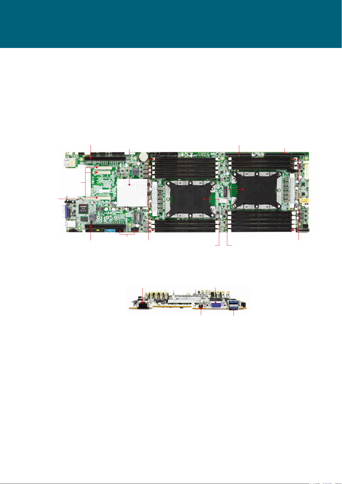
1�1 Component
Vela Serverboard
OCP V2.0 Mezz. (A+B+C)
Aspeed AST2500
Video + BMC
(from CPU0)
(from CPU0)
PCIe Gen3 x16
(from CPU0)
Intel PCH
(Lewisburg)
2 x SATA3
8 x DDR4 DIMM Slots
6 Channels (for CPU0)
RJ45 for BMC
Management
LGA3647 Socket P0 for
Intel Xeon Processor
Skylake/Cascade Lake
(CPU0)
VGA Port
by edge slot
LGA3647 Socket P0 for
Intel Xeon Processor
Skylake/Cascade Lake
(CPU1)
PCIe Gen3 x16 +8 (24lanes)
(from CPU1)
8 x DDR4 DIMM Slots
6 Channels (for CPU1)
Audio Jack
2 x USB 3.0COM Port By
Product specications and features are subject to change without prior notice.
1
1.2 Specications
Chapter 1. Product FeaturesVela User Manual
System
System BIOS
Processor
Support
CPU TDP
UPI Speeds
Socket Type
System
Memory
Expansion
Slots
BIOS Type
BIOS
Features
Intel® Xeon® Scalable Processors
(Skylake/Cascade Lake/Cascade Lake Refresh)
240W
10.4 GT/s, 9.6 GT/s
Socket P0 (LGA-3647 Socket)
• 6 x memory channels per CPU,
2 channels with 2DPC + 4 channels with 1DPC
• 16 x DIMM slots support:
DDR4 2933/2666MHz RDIMM/LRDIMM
- up to 256GB RDIMM SRx4
- up to 512GB RDIMM DRx4
- up to 2048GB RDIMM 3DS 8Rx4
- up to 1024GB LRDIMM QRx4
- up to 2048GB LRDIMM 3DS 8Rx4
• Intel® Optane™ DC Persistent Memory
(Apache Pass) support
• 2 x PCIe Gen3 slots
• 1 x OCP Mezz. V2.0 supports PCIe Gen3 x16
• 1 x high density connector supports 16 + 8
lanes of PCIe Gen3
Insyde UEFI BIOS
• ACPI
• PXE
• WOL
• AC loss recovery
• IPMI KCS interface
• SMBIOS
• Serial console redirection
• BIOS Recovery Mode
• SRIOV
• iSCSI
• TPM
On-board
Devices
Input/Output
SATA
BMC
Network
Controller
Graphics
SATA
LAN
USB
VGA
Serial Port
Other
Intel ® Lewisburg PCH on-chip solution
• 2 x SATA 6.0 Gb/s (by 2 x SATA 7 pin)
• 8 x SATA 6.0 Gb/s by edge slot for extension
Aspeed AST2500 Advanced PCIe Graphics &
Remote Management Processor
• Baseboard Management Controller
• Intelligent Platform Interface 2.0 (IPMI 2.0)
• iKVM, Media Redirection, IPMI over LAN,
Serial over LAN
• SMASH Support
• HTML5
• Via OCP Mezz. card/PCIe slots extension
• Realtek RTL8211E GbE Ethernet for BMC
dedicated management port
Aspeed AST2500 Advanced PCIe Graphics &
Remote Management Processor
• PCIe VGA/2D Controller
• 1920x1200@60Hz 32bpp
10 x SATA 6.0 Gb/s ports
• 2 x SATA 6.0 Gb/s (by 2 x SATA 7 pin) +
8 x SATA 6.0 Gb/s (by edge slot extension)
1 x GbE RJ45 dedicated to BMC management
• 2 x USB 3.0 Type A connectors
• 1 x USB internal pin-header to support 2 x
USB3.0/USB2.0
• 1 x USB internal pin-header to support 2 x
USB 2.0
• 1 x external VGA port
• 1 x internal VGA pin-header
(share with external VGA port)
• 1 x external COM port by 3.5mm phone jack
• 2 x internal COM pin-headers
1 x TPM 2.0 onboard
2

Chapter 1. Product FeaturesVela User Manual
1�3 Feature
The Vela server board offers the latest Xeon® Scalable Processors technology solutions
with compelling performance and provides premium power efficiency, which is optimized
for efficient performance platforms (storage, security and communications infrastructure).
By implementing Intel® Xeon® Scalable Processors, fully integrated microarchitecture
supports up to 72 lanes of PCIE Gen3, providing six channels per CPU with total sixteen
DIMM slots deployment which can support up to DDR4 2933/2666MHz, Vela server board
can meet both cost efficiency and performance requirement for lots of applications.
Featured with ground breaking technologies including Intel® Next Generation
Microarchitecture and Instruction Set (AVX-512, VMD, QAT - optional by PCH SKU), Speed
Shift Technology, UPI link speeds up to 10.4GT/s, the Vela server board enable next generation server solutions with an incredible leap in performance.
• Supports Intel® Xeon® Scalable Processors for highest server performance and improved power efficiency
• Supports 16 DDR4 DIMM slots for maximum memory performance
• Supports up to 72 lanes of PCIe Gen3 extension
(1) from CPU0: 1 x16 via OCP Mezz. V2.0;
2 x16 via PCIe x16 slots;
(2) from CPU1: the other 24 lanes via Max I/O®
• Onboard Baseboard Management Controller for system management and IPMI control
• Embedded components for 5+ year long life
• Rackmount Technology Extension (RTX) form factor utilizes full internal chassis vol-
ume for optimum I/O configurations
3
Spica User Manual
Chapter 2. Hardware SetupVela User Manual
Chapter 2� Hardware Setup
2�1 Central Processiong Unit
2�1�1 Processor Support
The server board includes two processor sockets (LGA3647) that provides one or two
processors of the Intel® Xeon® Processor Scalable Family and supports a Thermal
Design Power (TDP) of up to 240W on selected models.
4
Chapter 2. Hardware SetupVela User Manual
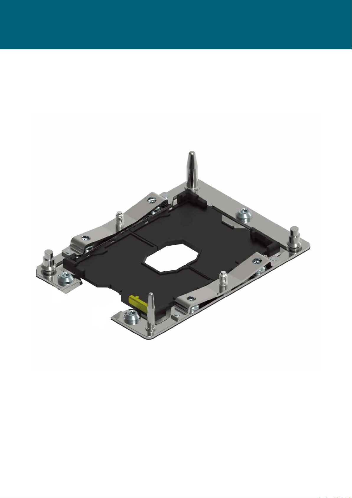
2�1�2 Processor Heat Sink Module and Processor Socket Assembly
Each processor socket on the server board is pre-assembled with a loading
mechanism that is designed to secure the Processor Heat Sink Module (PHM) to the
server board as shown below.
NOTE
Previous generations of the Intel Xeon Processors and heatsinks are not compatible
with the Intel Server Board S2600BP Product Family. Processor installation requires
that the processor be attached to the installation onto the server board.
5
Chapter 2. Hardware SetupVela User Manual
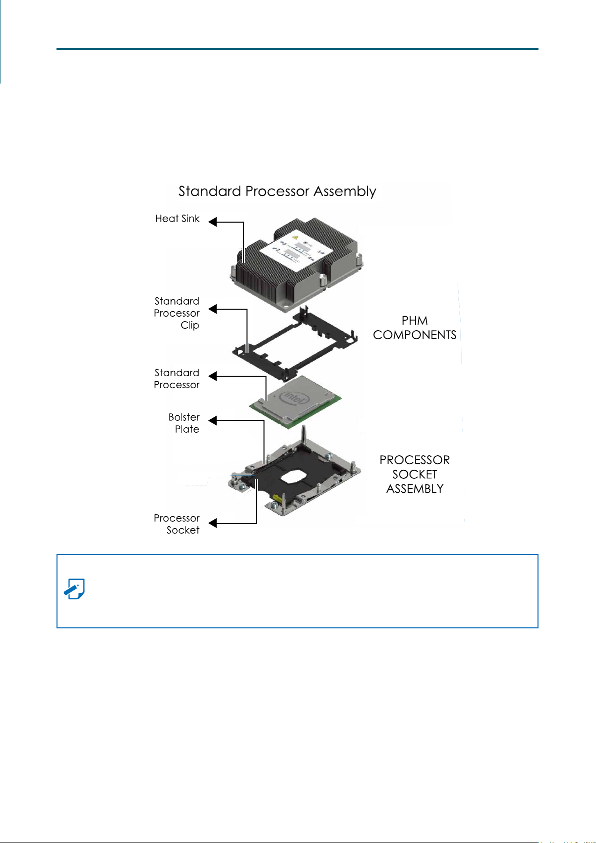
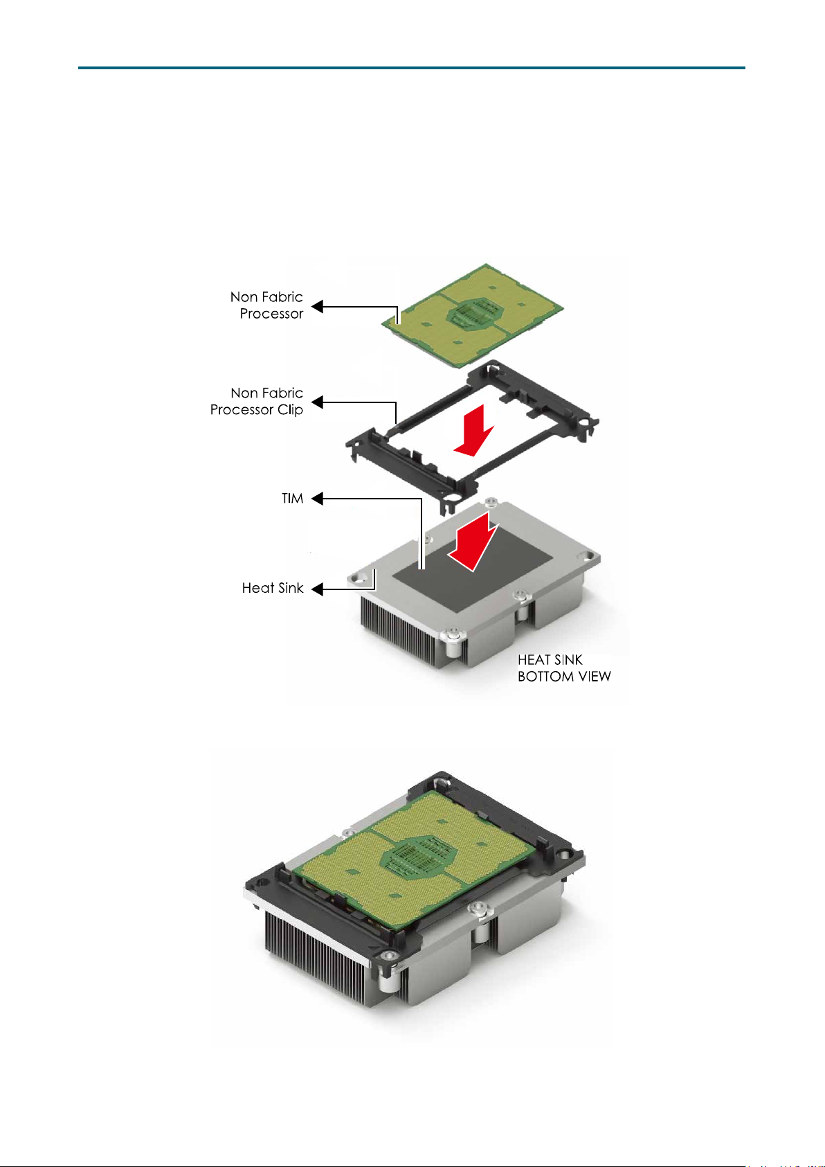
2�1�3 Processor Heat Sink Module
The PHM refers to the sub-assembly where the heat sink and processor are clipped
together onto the server board prior to installation. The PHM consists of the
components shown below.
Processor Heat Sink Module (PHM) Sub-Assembly
Processor Heatsink Module (PHM)
6
Chapter 2. Hardware SetupVela User Manual
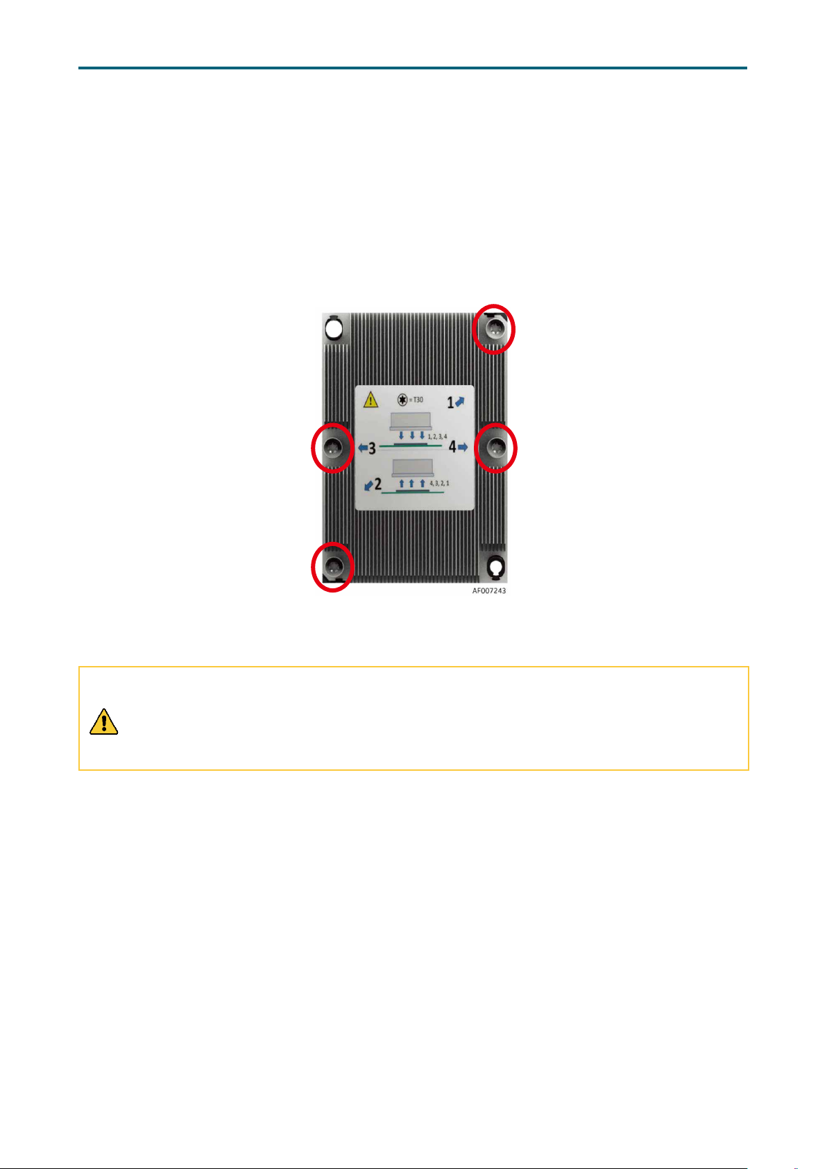
The PHM sits level with the processor socket assembly. The PHM is NOT installed
properly if it does not sit level with the processor socket assembly. Once the PHM is
seated over the processor socket assembly, the four heat sink torque screws must be
tightened in order as shown below.
Processor Heat Sink – Top View with Screw Tightening Order
CAUTION
Failure to tighten the heatsink screws in the specified order may cause damage to the
processor socket assembly. Heat sink screws should be tighted to 12 in-lbs torque
according to the indicated order on the top of the heatsink label.
7
2�2 System Memory
JDIMMC0
JDIMMB0
JDIMMA0
JDIMML0
JDIMMK0
JDIMMK1
JDIMMJ0
JDIMMJ1
JDIMMH0
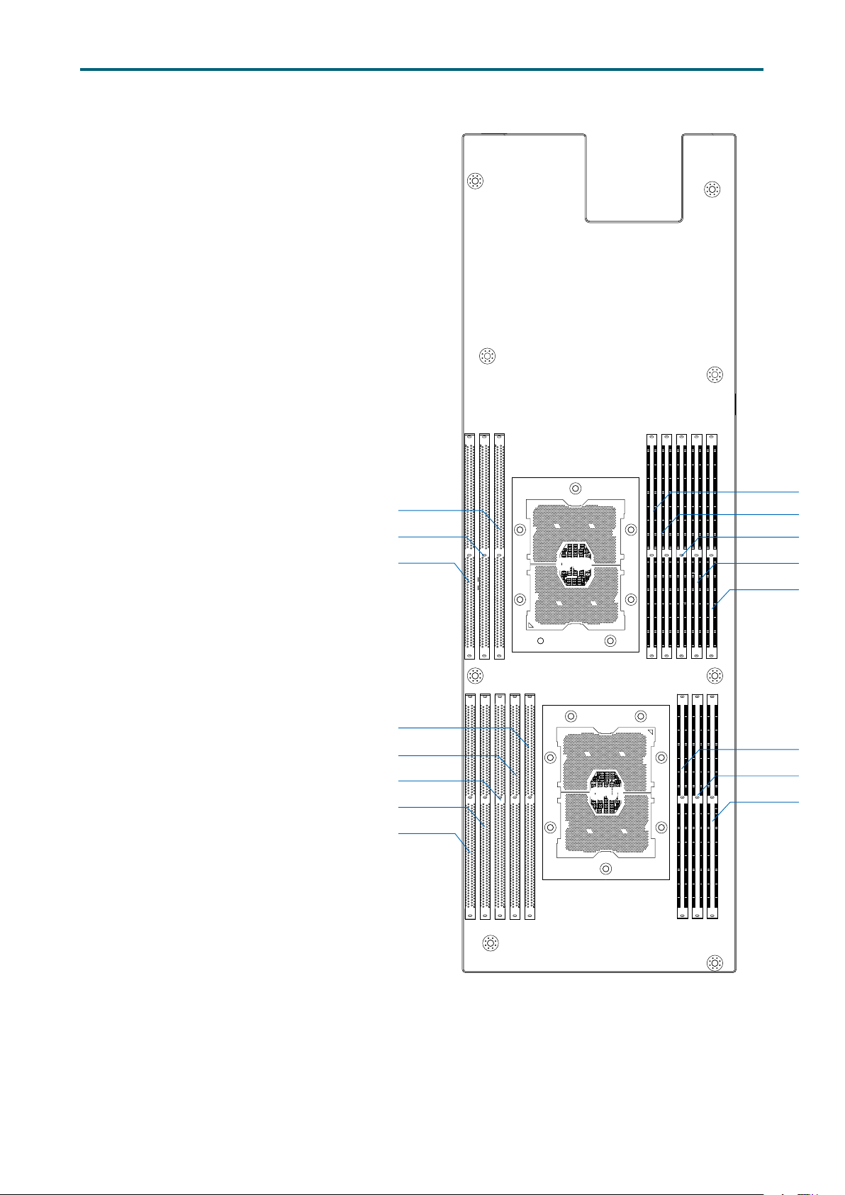
2�2�1 Placement
The DIMMs are displayed on
the Vela board as JDIMMC0/
JDIMMB0/JDIMMA0/JDIMMD0/
JDIMME1/ JDIMME0/JDIMMF1/
JDIMMF0/JDIMML0/JDIMMK0/
JDIMMK1/JDIMMJ0/JDIMMJ1/
JDIMMG0/JDIMMH0/JDIMMI0.
To ensure satisfactory
performance, you need to:
Verify the DIMM type:
This product supports DDR4
RDIMM/LRDIMM with EEC (Error
Correction Code).
Verify if all of the DIMMs
installed are of the same DIMM
type to avoid memory failure
and loss of performance speed.
CPU0
CPU0
Chapter 2. Hardware SetupVela User Manual
JDIMMD0
JDIMME1
JDIMME0
JDIMMF1
JDIMMF0
CPU1
CPU1
JDIMMG0
JDIMMI0
8
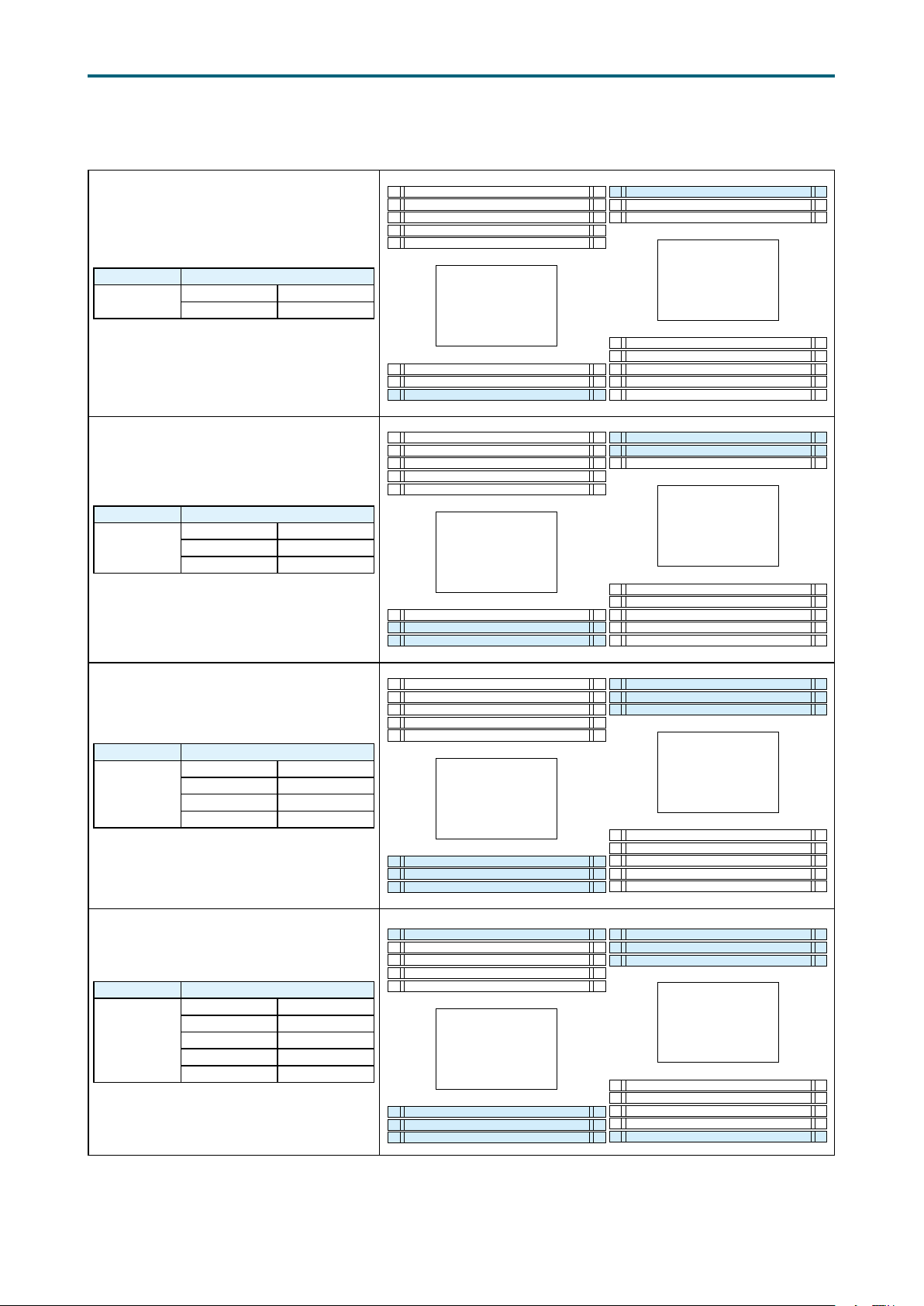
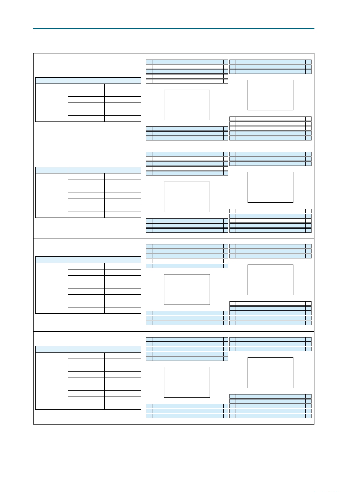
2�2�2 DIMM Population
JDIMMF0
JDIMMI0
JDIMMC0
JDIMML0
JDIMMF0
JDIMMI0
JDIMMC0
JDIMML0
JDIMMF0
JDIMMI0
JDIMMC0
JDIMMF0
JDIMMI0
JDIMMC0
JDIMML0
Chapter 2. Hardware SetupVela User Manual
DIMM Number DIMM Arrangement
2 DIMMs
CPU0 CPU1
JDIMMC0 JDIMMI0
DIMM Number DIMM Arrangement
CPU0 CPU1
4 DIMMs
JDIMMC0 JDIMMI0
JDIMMB0 JDIMMH0
JDIMMF1
JDIMME0
JDIMME1
JDIMMD0
CPU0
JDIMMA0
JDIMMB0
JDIMMF1
JDIMME0
JDIMME1
JDIMMD0
CPU0
JDIMMA0
JDIMMB0
JDIMMH0
JDIMMG0
CPU1
JDIMMJ1
JDIMMJ0
JDIMMK1
JDIMMK0
JDIMMH0
JDIMMG0
CPU1
JDIMMJ1
JDIMMJ0
JDIMMK1
JDIMMK0
DIMM Number DIMM Arrangement
CPU0 CPU1
6 DIMMs
JDIMMC0 JDIMMI0
JDIMMB0 JDIMMH0
JDIMMA0 JDIMMG0
DIMM Number DIMM Arrangement
CPU0 CPU1
JDIMMC0 JDIMMI0
8 DIMMs
JDIMMB0 JDIMMH0
JDIMMA0 JDIMMG0
JDIMMF0 JDIMML0
JDIMMF1
JDIMME0
JDIMME1
JDIMMD0
CPU0
JDIMMA0
JDIMMB0
JDIMMF1
JDIMME0
JDIMME1
JDIMMD0
CPU0
JDIMMA0
JDIMMB0
JDIMMH0
JDIMMG0
CPU1
JDIMMJ1
JDIMMJ0
JDIMMK1
JDIMMK0
JDIMML0
JDIMMH0
JDIMMG0
CPU1
JDIMMJ1
JDIMMJ0
JDIMMK1
JDIMMK0
9
Chapter 2. Hardware SetupVela User Manual
JDIMMF0
JDIMMI0
JDIMMC0
JDIMMF0
JDIMMI0
JDIMMC0
JDIMML0
JDIMMF0
JDIMMI0
JDIMMC0
JDIMML0
JDIMMF0
JDIMMI0
JDIMMC0
JDIMML0
DIMM Number DIMM Arrangement
CPU0 CPU1
JDIMMC0 JDIMMI0
10 DIMMs
JDIMMB0 JDIMMH0
JDIMMA0 JDIMMG0
JDIMMF0 JDIMML0
JDIMME0 JDIMMK0
DIMM Number DIMM Arrangement
CPU0 CPU1
JDIMMC0 JDIMMI0
JDIMMB0 JDIMMH0
12 DIMMs
JDIMMA0 JDIMMG0
JDIMMF0 JDIMML0
JDIMME0 JDIMMK0
JDIMMD0 JDIMMJ0
JDIMMF1
JDIMME0
JDIMME1
JDIMMD0
CPU0
JDIMMA0
JDIMMB0
JDIMMF1
JDIMME0
JDIMME1
JDIMMD0
CPU0
JDIMMA0
JDIMMB0
JDIMMH0
JDIMMG0
CPU1
JDIMMJ1
JDIMMJ0
JDIMMK1
JDIMMK0
JDIMMH0
JDIMMG0
CPU1
JDIMMJ1
JDIMMJ0
JDIMMK1
JDIMMK0
DIMM Number DIMM Arrangement
CPU0 CPU1
JDIMMC0 JDIMMI0
JDIMMB0 JDIMMH0
14 DIMMs
JDIMMA0 JDIMMG0
JDIMMF0 JDIMML0
JDIMME0 JDIMMK0
JDIMMD0 JDIMMJ0
JDIMMF1 JDIMMK1
DIMM Number DIMM Arrangement
CPU0 CPU1
JDIMMC0 JDIMMI0
JDIMMB0 JDIMMH0
JDIMMA0 JDIMMG0
16 DIMMs
JDIMMF0 JDIMML0
JDIMME0 JDIMMK0
JDIMMD0 JDIMMJ0
JDIMMF1 JDIMMK1
JDIMME1 JDIMMJ1
JDIMMF1
JDIMME0
JDIMME1
JDIMMD0
CPU0
JDIMMA0
JDIMMB0
JDIMMF1
JDIMME0
JDIMME1
JDIMMD0
CPU0
JDIMMA0
JDIMMB0
JDIMMH0
JDIMMG0
CPU1
JDIMMJ1
JDIMMJ0
JDIMMK1
JDIMMK0
JDIMMH0
JDIMMG0
CPU1
JDIMMJ1
JDIMMJ0
JDIMMK1
JDIMMK0
JDIMML0
10
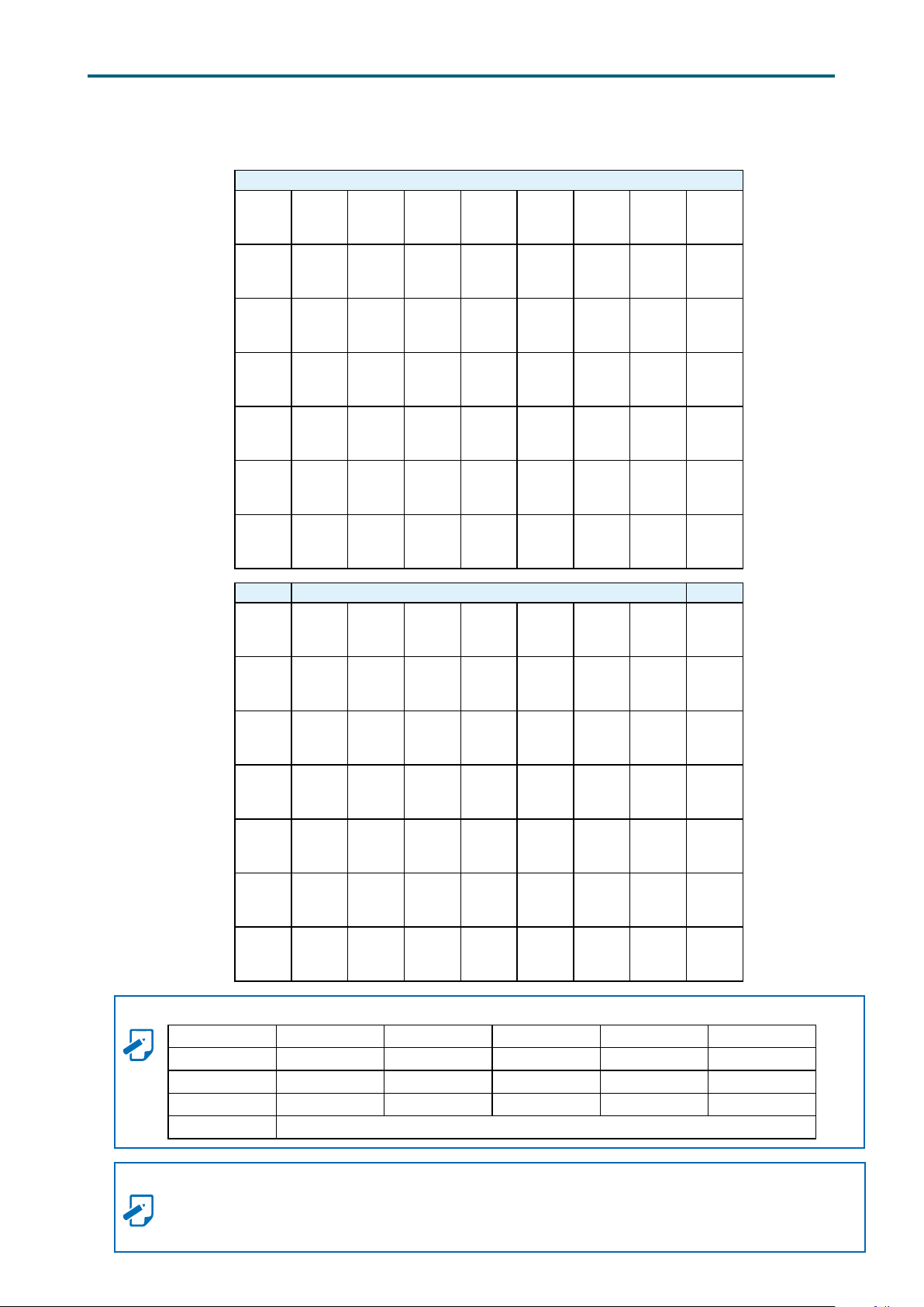
2�2�3 DCPMM DIMM Population
DIMM JDIMMF0 JDIMMF1 JDIMME0 JDIMME1 JDIMMD0 JDIMMA0 JDIMMB0 JDIMMC0
Chapter 2. Hardware SetupVela User Manual
CPU0
App Direct
Mode
Memory
Mode
Mixed
Memory
Mode
App Direct
Mode
Memory
Mode
Mixed
Memory
Mode
DCPMM DRAM1 DCPMM DRAM1 DRAM1 DCPMM DRAM1 DRAM1
DCPMM DRAM2 DCPMM DRAM2 DRAM2 DCPMM DRAM2 DRAM2
DCPMM DRAM3 DCPMM DRAM3 DRAM3 DCPMM DRAM3 DRAM3
DCPMM DRAM1 DCPMM DRAM1 DRAM1 DCPMM DRAM1 DRAM1
DCPMM DRAM2 DCPMM DRAM2 DRAM2 DCPMM DRAM2 DRAM2
DCPMM DRAM3 DCPMM DRAM3 DRAM3 DCPMM DRAM3 DRAM3
CPU1
DIMM JDIMMK0 JDIMMK1 JDIMMJ0 JDIMMJ1 JDIMML0 JDIMMG0 JDIMMH0 JDIMMI0
App Direct
Mode
- - - - - -
Memory
Mode
Mixed
Memory
Mode
App Direct
Mode
Memory
Mode
Mixed
Memory
Mode
- - - - - -
- - - - - -
DCPMM DRAM1 DCPMM DRAM1 DCPMM DRAM1 DRAM1 DRAM1
DCPMM DRAM2 DCPMM DRAM2 DCPMM DRAM2 DRAM2 DRAM2
DCPMM DRAM3 DCPMM DRAM3 DCPMM DRAM3 DRAM3 DRAM3
NOTE
DIMM Type RDIMM 3DS RDIMM LRDIMM 3DS LRDIMM Capacity
DRAM1
DRAM2
DRAM3
DCPMM Any Capacity (Uniformly for all channels for system configuration)
Any Capacity
≥32GB
Any Capacity
NOTE
Please abide to the DCPMM population rules listed below for your system to function accordingly.
• There is only a maximun of 1 DCPMM in each channel.
• Populate DCPMM DIMM on IMC0 before IMC1.
11
Chapter 2. Hardware SetupVela User Manual
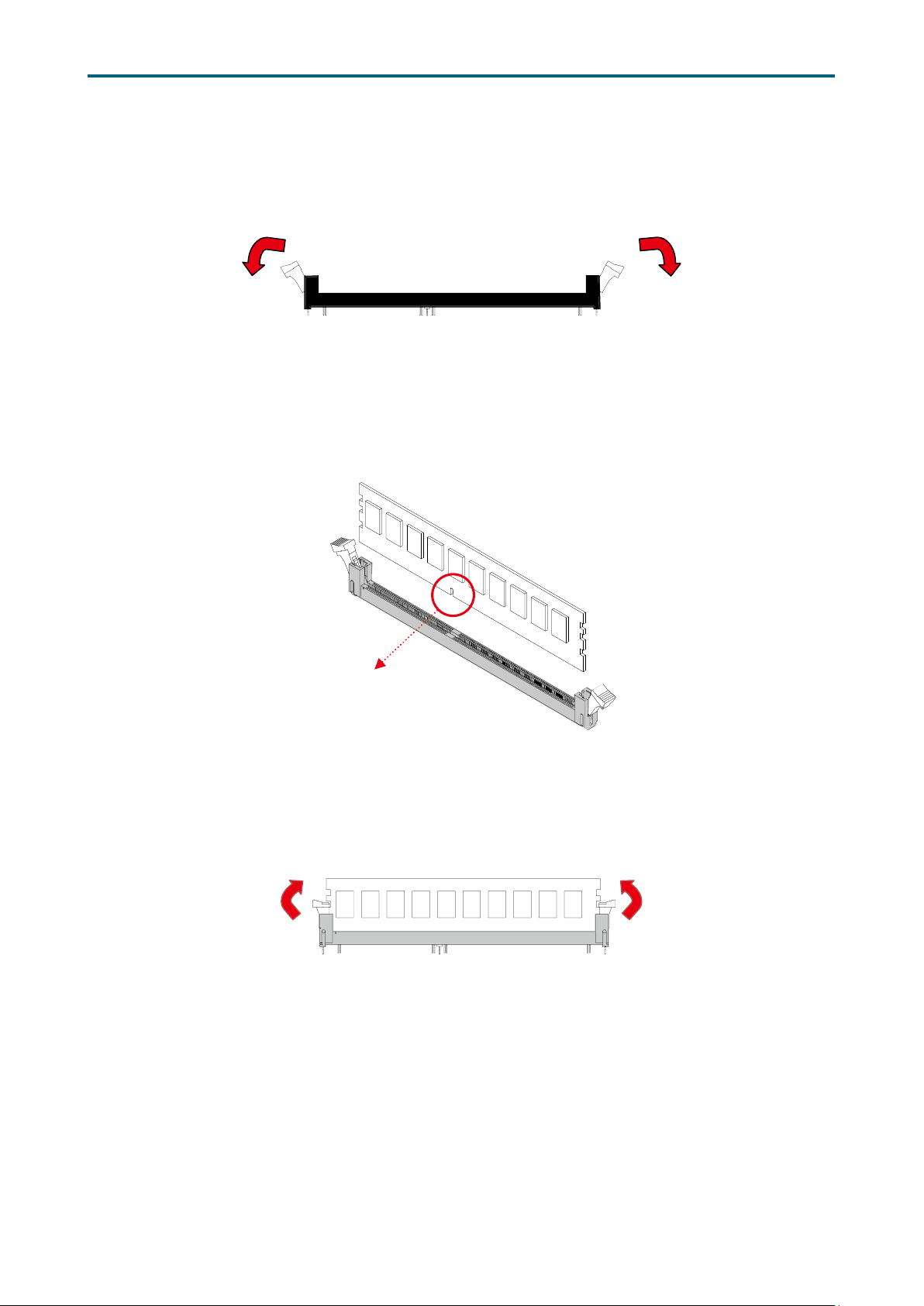
DIMM n
2�2�4 Installation Step 1 Unlock the DIMM socket by pressing the retaining clips outward.
Step 2 Insert the memory module into the slot. Make sure that the DIMM notch is
accurately positioned.
otch
Step 3 Close the retaining clips to complete installation.
12
Chapter 3. Motherboard SettingsVela User Manual
Chapter 3� Motherboard Settings
This section provides illustrations that display the internal jumpers, connectors, and
system LED indicators on the Vela motherboard. The motherboard layout and essential
connectors are listed below for your reference.
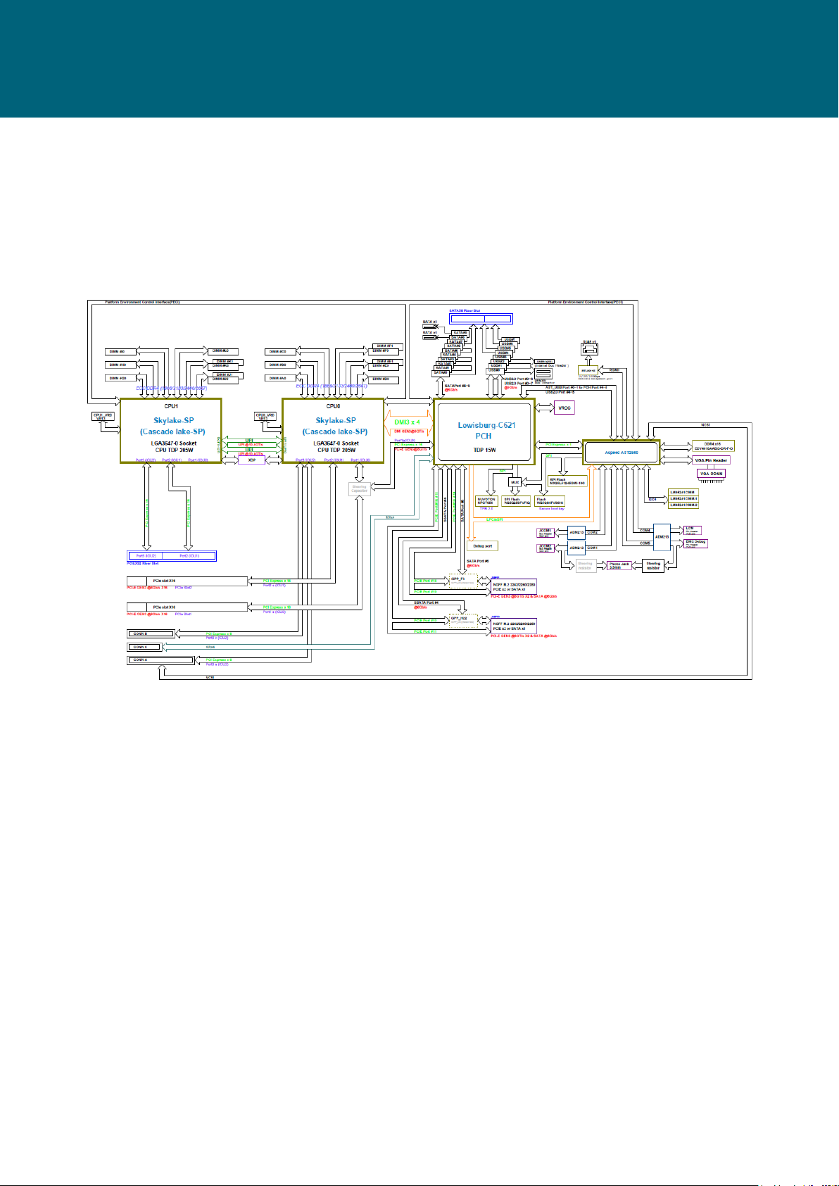
3�1 Block Diagram
13
Chapter 3. Motherboard SettingsVela User Manual
3�2 Content List
Connector and Header Location Connector and Header Location
1 VGA Header JVGA_INT 17
2a
OCP Mezzaine
2b
Connector
2c
3a
PCIe Connector
3b
4a
COM Header
4b
CN1~3 18
PCIE1
PCIE2
JCOM1
JCOM2
5 LCM Header JLCM 21 VROC Key JRAID_KEY
6a
BMC GPIO Header
6b
7a
7b
8
2
BMC I
C Header
Power Supply
Connector (1 x 4 pin)
JBMC_GPIO1
JBMC_GPIO2
JBMC_I2C1
JBMC_I2C2
JPWR_OCP
9 BIOS SPI ROM Socket JSPI_BIOS
Front panel Header for
Rack
Power Supply Connector
(2 x 4 pin)
JRACK
JPWR1
19 LAN Header JLAN2
Power Supply Connector
20
(2 x 10 pin)
SATA DOM Power
22
Header
J11
JDOM_PWR
23 Buzzer JBUZZER
24a
JNGFF Connector
24b
25a
Serial ATA Header
25b
JNGFF1
JNGFF2
SATA1
SATA2
10 Battery Socket JBAT1 26 Front I/O USB Header JUSB_INT1
11 PMBUS Header JPMBUS 27 Speaker JSPR
PCIE Hot-Plug SMB
12
Header
JPCIE_HP 28 PCH_GPIO Header JPCH_GPIO
13 Front Panel Header JFRNT_SSI 29 VRM SMB Header JSMB_VR
14a
SAMTEC Connector
14b
Power Supply
15
Connector (1 x 5 pin)
Power Supply
16
Connector (2 x 7 pin)
PCIE3
PCIE4
30 PCH SSGPIO Header JSSGPIO
J13 31 PCH SGPIO Header JSGPIO
JPWR2
Jumper Location Jumper Location
A Chassis Intrusion JINTRUDER G CMOS Jumper JCMOS
B NCSI_RXER J5 H NTB Jumper JNTB
BMC Debug Port
C
Configuration Jumper
Top Swap Override
D
Jumper
ME Force Recovery
E
Mode Jumper
No Reboot Mode
F
(Watch Dog) Jumper
J9 I
J8 J
J7 K BMC Reset Jumper JBMC_RST
J6 L BMC ARM Jumper JBMC_DIS
Power Good Lock
Jumper
Flash Descriptor
Security override
Jumper
JPG_LOCK
J4
14
 Loading...