

Page 1

UM_Ursa_v1.5_122218
Ursa
Server Motherboard
User's Manual
Page 2

Contents
Table of Contents
Preface ������������������������������������������������������������������������������������������������� i
Safety Instructions ������������������������������������������������������������������������������ ii
About This Manual ������������������������������������������������������������������������������ iii
Chapter 1� Product Features ��������������������������������������������������������������1
1�1 Components �������������������������������������������������������������������������������������1
1.2 Specications ����������������������������������������������������������������������������������� 2
1�3 Feature ���������������������������������������������������������������������������������������������3
Chapter 2� Hardware Setup ����������������������������������������������������������������4
2�1 Central Processing Unit Setup ���������������������������������������������������������� 4
2.1.1 Processor Installation ........................................................................................4
2.1.2 Heatsink ..............................................................................................................5
2�2 System Memory Setup ���������������������������������������������������������������������� 6
2.2.1 DIMM Installation ...............................................................................................6
2.2.2 DIMM Location ...................................................................................................7
2.2.3 DIMM Slot Installation Order..............................................................................8
Chapter 3� Motherboard Settings �������������������������������������������������������9
3�1 Motherboard Block Diagram ��������������������������������������������������������������9
3�2 Motherboard Layout ������������������������������������������������������������������������10
3�3 Content List ������������������������������������������������������������������������������������ 11
3�4 Connetor and Jumper����������������������������������������������������������������������12
3.4.1 Connector ......................................................................................................... 12
3.4.2 Jumper ............................................................................................................. 23
Chapter 4. BIOS Conguration Settings ������������������������������������������� 24
4�1 Navigation Keys ������������������������������������������������������������������������������ 24
4�2 BIOS Menu ��������������������������������������������������������������������������������������25
4�3 Main �����������������������������������������������������������������������������������������������26
4.3.1 Main .................................................................................................................. 26
4�4 Advanced ���������������������������������������������������������������������������������������� 27
4.4.1 iSCSI Conguration ......................................................................................... 27
4.4.2 Trusted Computing .......................................................................................... 27
Page 3

4.4.3 Serial Port Console Redirection ...................................................................... 28
4.4.4 PCI Subsystem Settings .................................................................................. 28
4.4.5 Network Stack Conguration .......................................................................... 28
4.4.6 Memory RAS Conguration Setup .................................................................. 28
4.4.7 CSM Conguration .......................................................................................... 29
4.4.8 IIO0 Conguration ........................................................................................... 29
4.4.9 IIO1 Conguration ............................................................................................ 29
4.4.10 IOAT Conguration ........................................................................................ 29
4.4.11 Intel VT for Directed I/O ................................................................................ 30
4.4.12 USB Conguration ......................................................................................... 30
4�5 Platform �����������������������������������������������������������������������������������������31
4.5.1 PCH Conguration ........................................................................................... 31
4.5.2 MIscellaneous Conguration .......................................................................... 31
4.5.3 Server ME Conguration ................................................................................. 31
4.6 Socket Conguration ����������������������������������������������������������������������32
4.6.1 Processor Conguration ................................................................................. 32
4.6.2 Common RefCode Conguration .................................................................... 32
4.6.3 UPI Conguration ............................................................................................ 33
4.6.4 Common RefCode Conguration .................................................................... 33
4.6.5 Memory Conguratiuon .................................................................................. 33
4.6.6 Memory Map .................................................................................................... 33
4.6.7 Memory RAS Conguration ............................................................................. 33
4�7 BMC �����������������������������������������������������������������������������������������������34
4.7.1 FB-2 Timer ....................................................................................................... 34
4.7.2 FB-2 Timer Policy ............................................................................................ 34
4.7.3 BMC Network Conguration ........................................................................... 34
4�8 Security ������������������������������������������������������������������������������������������35
4.8.1 Security ............................................................................................................ 35
4.8.2 Secure Boot ...................................................................................................... 36
4�9 Boot ������������������������������������������������������������������������������������������������37
4.9.1 Boot .................................................................................................................. 37
4�10 Save and Exit ��������������������������������������������������������������������������������38
4.10.1 Save and Exit.................................................................................................. 38
4�11 Update Requirement ���������������������������������������������������������������������39
4.11.1 Utility .............................................................................................................. 39
Contents
Page 4

4.11.2 Update under EFI Shell .................................................................................. 39
4.11.3 Update under Linux ...................................................................................... 39
4.11.4 Update under Windows ................................................................................ 39
Chapter 5. BMC Conguration Settings �������������������������������������������� 40
5�1 Login ����������������������������������������������������������������������������������������������40
5�2 Web GUI ���������������������������������������������������������������������������������������� 41
5.2.1 User Information and Quick Button ............................................................... 41
5.2.2 BMC Watchdog ................................................................................................ 42
5.2.3 System LED Indicator ...................................................................................... 42
5.2.4 LAN ................................................................................................................... 43
5.2.5 System Event Log (SEL) .................................................................................. 43
5.2.6 Serial Interface ................................................................................................. 44
5.2.7 RMCP(IPMI v1.5)/RMCP + (IPMI v2.0) and Payload Support ....................... 45
5.2.8 Remote KVM .................................................................................................... 46
5.2.9 BMC Booting .................................................................................................... 48
Chapter 6� Technical Support ����������������������������������������������������������� 49
Contents
Page 5
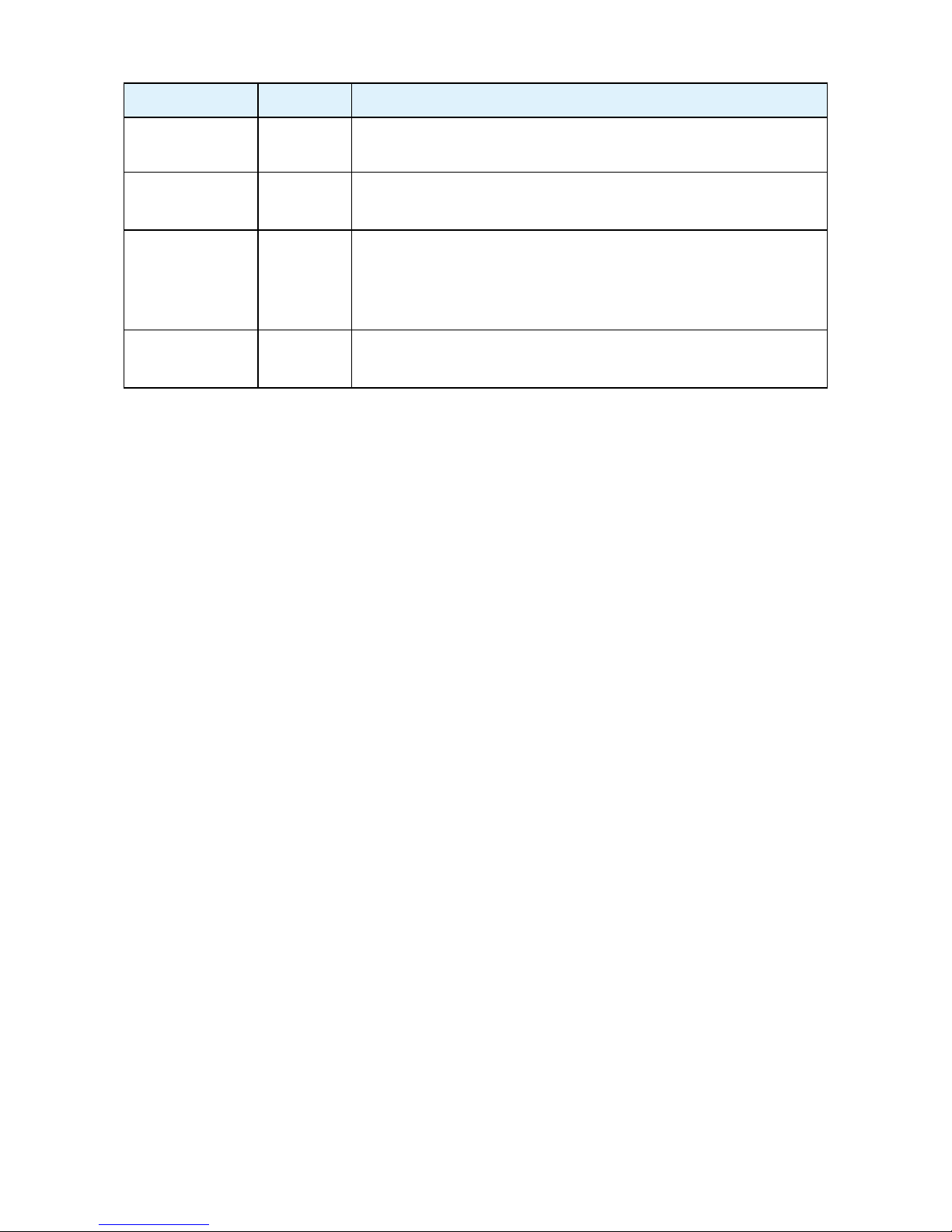
Document Release History
Release Date Version Update Content
September
2018
1 User's Manual release to public.
October
2018
1.2 1. Update MB Layout
November
2018
1.4
1. BIOS update
2. BMC update
3. Specications
December
2018
1.5 1. Update new cover
Contents
Page 6

Copyright © 2018 AIC, Inc� All Rights Reserved�
This document contains proprietary information about
AIC products and is not to be disclosed or used except in
accordance with applicable agreements.
Page 7

Copyright
No part of this publication may be reproduced, stored in a retrieval system, or
transmitted in any form or by any means, electronic, mechanical, photo-static, recording
or otherwise, without the prior written consent of the manufacturer.
Trademarks
All products and trade names used in this document are trademarks or registered
trademarks of their respective holders.
Changes
The material in this document is for information purposes only and is subject to change
without notice.
Warning
1. A shielded-type power cord is required in order to meet FCC emission limits and also
to prevent interference to the nearby radio and television reception. It is essential
that only the supplied power cord be used.
2. Use only shielded cables to connect I/O devices to this equipment.
3. You are cautioned that changes or modifications not expressly approved by the
party responsible for compliance could void your authority to operate the equipment.
Disclaimer
AIC shall not be liable for technical or editorial errors or omissions contained herein.
The information provided is provided "as is" without warranty of any kind. To the
extent permitted by law, neither AIC or its afliates, subcontractors or suppliers will be
liable for incidental, special or consequential damages including downtime cost; lost
profits; damages relating to the procurement of substitute products or services; or
damages for loss of data, or software restoration. The information in this document
is subject to change without notice.
Preface
i
Page 8

ii
Safety Instructions
When installing, operating, or performing maintenance on this equipment, the following
safety precautions should always be taken into account in order to reduce the risk of re,
electric shock, and personal injury.
Carefully read the safety instructions below before using this product.
• Observe all of the warning and instruction signs distinctively marked on the product.
• Before performing system installations, please consult the User’s Manual provided
with this product.
• Do not place this product on an uneven or weak surface (unstable cart, stand, table,
ect.) that might induce the product to fall and sustain serious damage.
• Install only the equipment or device identied in the User’s Manual. Deploying other
equipment or device with this motherboard could invoke improper connection of
circuitry that leads to re or personal injury.
• This product should only be operated with the type of power source indicated on the
marked label. If you are questionable about which type of power supply is used in your
area, consult your dealer or local Power Company.
• Disconnect the power supply module before removing power from the system.
• Unplug this product from the wall outlet before cleaning. Use a damp cloth for
cleaning. Do not use liquid cleaners or aerosol cleaners.
• Do not use this product near a water source, including faucet and lavatory.
• Never spill liquids of any kind on this product.
• Never shove objects of any kind into this product’s open slots, as they may touch
dangerous voltage points or short out parts and could result in re or electric shock.
• Do not block or cover slots and openings in this unit, as they were made for ventilation
and prevent this unit from overheating. Do not place this product in a built-in
installation unless proper ventilation is available.
• Do not disassemble this product. This product should only be taken apart by trained
personnel. Opening or removing covers and circuit boards may expose you to electric
shock or other risks. Incorrect reassembly can also cause electric shock when the
unit is subsequently used.
• Risk of explosion is possible if battery is replaced with an incompatible type. Dispose
of used batteries accordingly.
• This product is equipped with a three-wire grounding type plug, a plug with a third
(grounding) pin. As a safety feature, this plug is intended to t only into a grounding
type power outlet. If you are unable to insert the plug into the outlet, contact your
electrician to replace the outlet. Do not remove the grounding type plug or use a
3-Prong To 2-Prong Adapter to circumvent the safety feature; doing so may result in
electric shock and/or damage to this product.
Page 9

About This Manual
Thank you for selecting and purchasing the Ursa Serverboard.
This user's manual is provided for professional technicians to perform easy hardware
setup, basic system congurations, and quick software startup. This document pellucidly
presents a brief overview of the product design, device installation, and rmware settings
for the Ursa motherboard. For the latest version of this user's manual, please refer to the
AIC website.http://www.aicipc.com/tw/productdetail/51085.
Chapter 1 Product Features
This chapter delivers the overall layout of the product, including the fundamental
components on the motherboard, design specications, and noteworthy features. Ursa is
an ideal server grade motherboard that is specically designed to accommodate diverse
enterprises for managing heavy workloads, databases, nearline applications, and cloud
deployments. This product supports two Intel® Xeon™ E5-2600 v5 processors.
Chapter 2 Hardware Setup
This chapter displays an easy installation guide for assembling the CPU(Central
Processing Unit) and memory module. Utmost caution for proceeding to set up the
hardware is highly advised. The components on the motherboard are highly fragile and
vulnerable to exterior influence. Do not attempt to endanger the device by placing the
device in a potentially unstable or hazardous surroundings, including positioning the
device on an uneven grounds or humid environments.
Chapter 3 Motherboard Settings
This chapter elaborates the overall layout of the server motherboard, including
multifarious connectors and jumpers. These descriptions assist users to configure
different settings and functions of the motherboard, as well as to conrm the location of
each connector and jumper.
Chapter 4 BIOS Conguration Settings
This chapter introduces the key features of BIOS, including the descriptions and option
keys for diverse functions. These details provide users to effortlessly navigate and
congure the input/output devices.
Chapter 5 BMC Conguration Settings
This chapter illustrates the diverse functions of IPMI BMC, including the details on logging
into the web page and assorted denitions. These descriptions are helpful in conguring
various functions through Web GUI without entering the BIOS setup. For more information
of BMC congurations, please refer to IPMI BMC (Aspeed2500) User's Manual for a more
detailed description.
Chapter 6 Technical Support
For more information or suggestion, please contact the nearest AIC corporation
representative in your district or visit the AIC website: http://www.aicipc.com/en. It is our
greatest honor to provide the best service for our customers.
iii
Page 10
Chapter 1. Product FeaturesUrsa User Manual
1
Ursa User Manual Chapter 1. Product Features
Chapter 1� Product Features
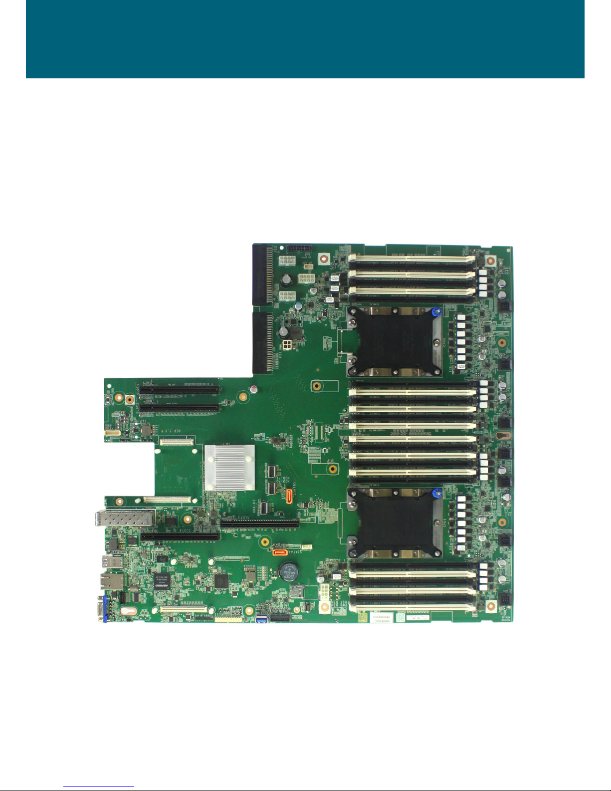
This section describes the hardware specications and features of the Ursa motherboard.
The fundamental components of the Ursa severboard are provided below.
1�1 Components
Ursa Serverboard
Product specications and features are subject to change without prior notice.
Page 11
2
Chapter 1. Product FeaturesUrsa User Manual
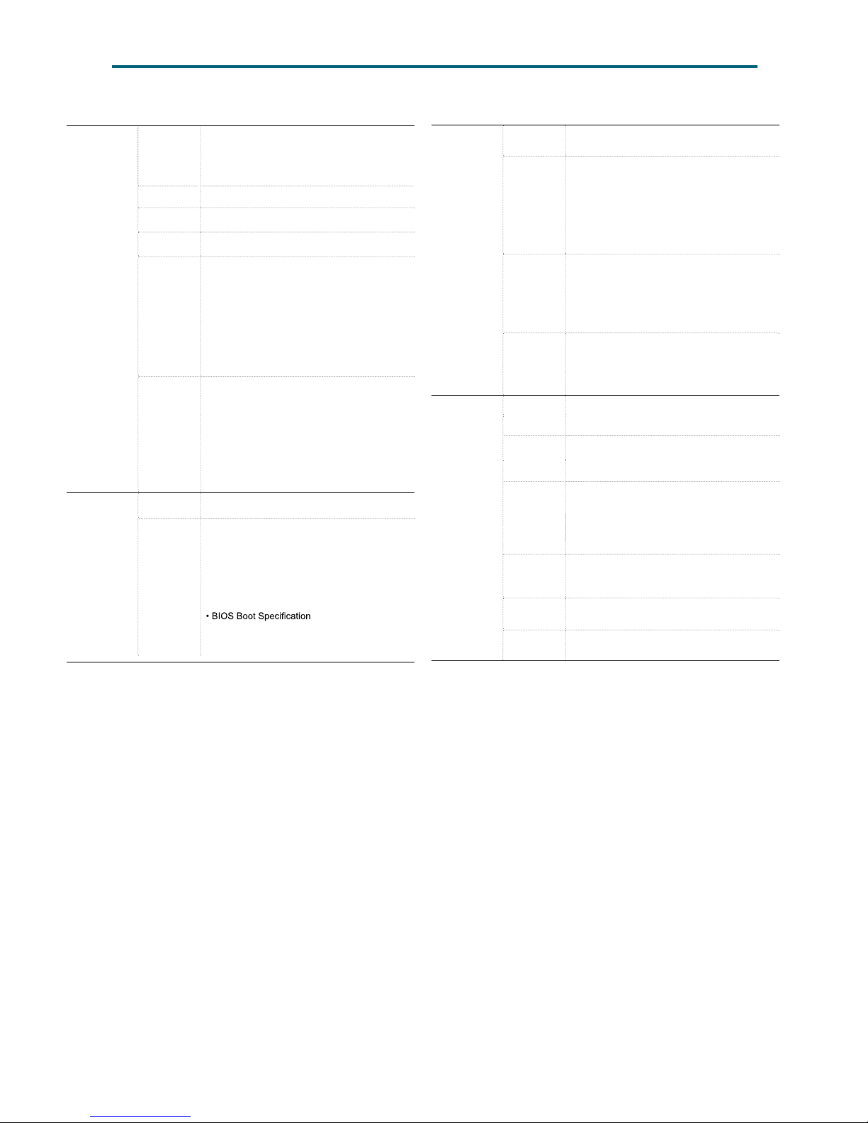
1.2 Specications
System
Processor
Support
Intel® Xeon® Scalable Processors
(Skylake and next gen. CPU)
UPI Speeds
9.6 GT/s, 10.4 GT/s
Socket Type
Socket P0 (LGA-3647 Socket)
System
Memory
• DDR4 2400 (2DPC) /2666(1DPC)MHz
Feature support up to DDR4 2933MHz
by next gen. process upgrade
• Total 24 memory slots ;
6 channel per CPU (2DPC)
• Up to 3TB 3DS ECC RDIMM/LRDIMM
Expansion
Slots
• 4 x PCI Express Gen3 x16;
(2 from CPU0 + 2 from CPU1)
• 2 x OCP Mezz. support:
1 PCI Express Gen3 x16 (V2.0)
1 PCI Express Gen3 x8 (V1.2)
BIOS Type
AMI UEFI BIOS
BIOS
Features
• ACPI
• PXE
• AC loss recovery
• IPMI KCS interface
• SMBIOS
• Serial console
• BIOS Recovery Mode
On-board
Devices
SATA
Intel® Lewisburg PCH on-chip solution
• 14 x SATA 6.0 Gb/s
IPMI
Aspeed AST2500 Advanced PCIe Graphics &
Remote Management Processor
• Baseboard Management Controller
• Intelligent Platform Interface 2.0 (IPMI 2.0)
• iKVM, Media Redirection, IPMI over LAN,
Serial over LAN
• SMASH Support
• HTML5
Network
Controller
•
Intel ® PCH (C622) Integrated 10GbE LAN Controller
support 2 x 10GbE SFP+
• Networking options provided via OCP
Mezzanine extension
• Broadcom BCM54612 (GbE) for BMC
dedicate management port
Graphics
Aspeed AST2500 Advanced PCIe Graphics &
Remote Management Processor
• PCIe VGA/2D Controller
• 1920x1200@60Hz 32bpp
Input/Output
SATA
• 14 x SATA 6.0 Gb/s ports, including
12 x SATA 6.0 Gb/s (by 3 x mini-SAS HD)
2 x SATA 6.0 Gb/s (by 2 SATA 7 pins)
LAN
• 2 x 10G SFP+
• 1 x GbE RJ45 dedicated to BMC
management
USB
• 2 x USB 3.0 Type-A connectors
• 1 x USB internal pin-header to support
2 x USB 2.0/3.0
• 1 x USB internal vertical Type-A connector to
support USB 2.0/3.0
VGA 1 x external VGA port
Serial Port 1 x DB-9 COM port
Others 1 x TPM connector
•
Intel® Optane DC Persistant Memory
(Apache Pass) support
CPU TDP
205W
Page 12

3
Chapter 1. Product FeaturesUrsa User Manual
The Ursa server board offers the latest Xeon® Scalable Processors technology
solutions with compelling performance and provides premium power efficiency, which
is optimized for efcient performance platforms (storage, security and communications
infrastructure).
By implementing Intel® Xeon® Scalable Processors, fully integrated microarchitecture
support four PCIE Gen3 x16 slots, plus two OCP Mezzanine extension connectors (one
is with x16 lanes, the other one is x8). Ursa server board provide dual 10GbE SFP+
networking interface, providing six channels per CPU with total twenty-four DIMM slots
deployment which can support up to DDR4 2400/2666MHz (feature support up to DDR4
2933 MHz by next gen. process upgrade).
Featured with ground breaking technologies including Intel® Next Generation
Microarchitecture and Instruction Set (AVX-512, VMD, QAT - optional by PCH SKU), Speed
Shift Technology, UPI link speeds up to 10.4GT/s, the Ursa server board enable next
generation server solutions with an incredible leap in performance.
• Supports Intel® Xeon® Scalable Processors (Platinum, Gold, Silver, Bronze) for
highest server performance and improved power efciency
• Supports 24 DDR4 DIMM slots for maximum memory performance
• Supports four PCI Express Gen3 x16 slots (2 from CPU0+ 2 from CPU1)
• Supports one OCP Mezzanine V2.0 up to PCI Express Gen3 x16 extension; one OCP
Mezzanine V1.2 up to PCI Express Gen3 x8 extension
• Onboard dual ports 10GbE SFP+ supported by Intel® Lewisburg PCH
• Supports up to 14 SATA 6Gb/s ports
• Supports two CRPS PSU direct connection for power input
• Onboard Baseboard Management Controller for system management and IPMI
control
1�3 Feature
Page 13
4
Chapter 2. Hardware Setup
Ursa User Manual
This section describes a simple instruction guide for installing the hardware components
on the serverboard system. Turn off and unplug all system and peripheral devices before
proceeding.
2�1 Central Processing Unit Setup
The serverboard supports dual Xeon scalable processors and Socket P0 (LGA-3647).
2�1�1 Processor Installation
To ensure a safe and easy setup, you need to prepare before installation:
a T20 Torx screwdriver
ESD wrist strap/mat and conductive foam pad
CAUTION
The pins of the processor socket are vulerable and easily susceptible to damage if ngers or any
foreign objects are pressed against them. Please keep the socket protective cover on when the
processor is not installed.
WARNING
When unpacking a processor, hold the processor only by its edges to avoid touching the contacts.
Procedure:
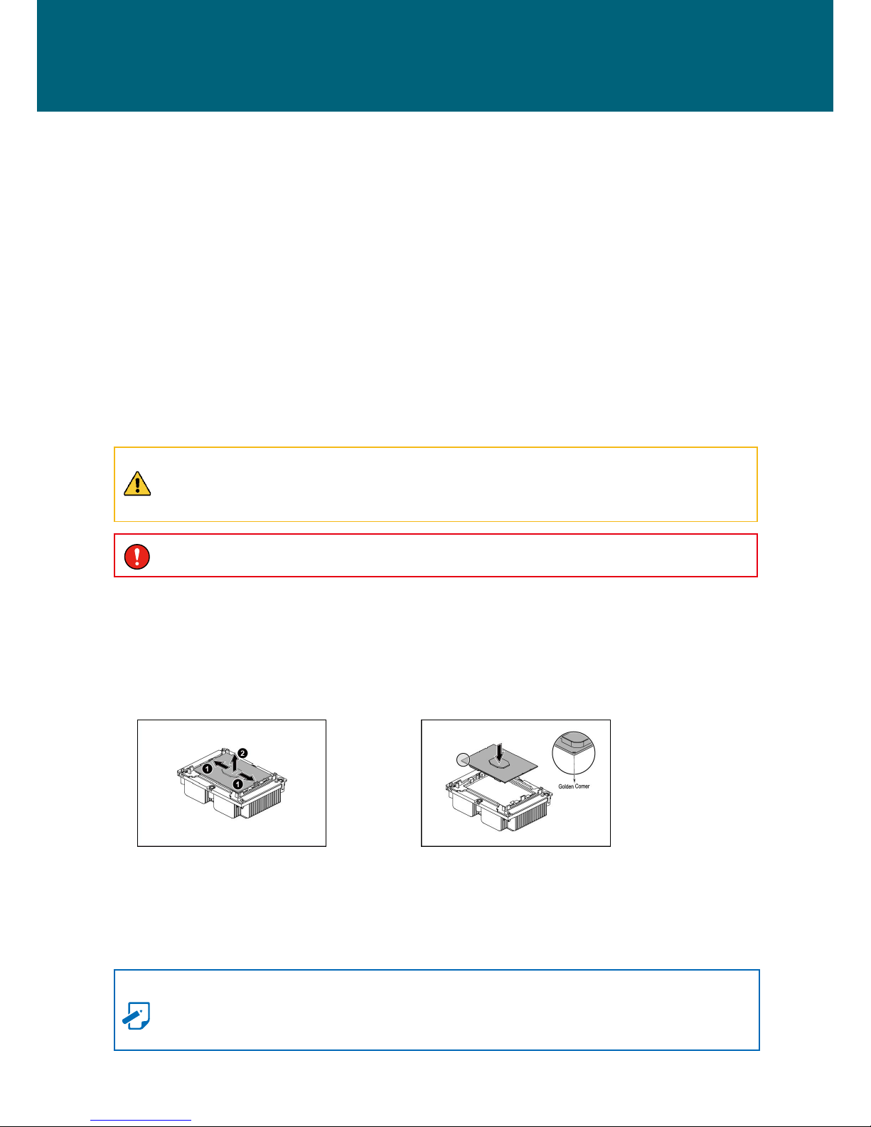
Installation
Step 1 Push the two locking tabs that secure the processor.
Step 2 Carefully remove the processor from the socket.
Removal
Step 1 Align the gold corner on the processor with the socket.
Step 2 Insert the processor into the socket. Make sure the processor is rmly locked
into the socket.
NOTE
The processor can only be placed in one direction. Handle the processor with care
during installation to avoid damage to the processor.
Chapter 2� Hardware Setup
Page 14

5
Chapter 2. Hardware SetupUrsa User Manual
2�1�2 Heatsink
To ensure a safe and easy setup, you need to prepare before installation:
2 heatsinks that support the motherboard.
Procedure:
Installation
Step 1 Position the heatsink on top of the CPU.
Step 2 Secure the screws on the heatsink.
Removal
Step 1 Dislodge the screws x 4 on the heatsink.
Step 2 Remove the heatsink by lifting it upward.
NOTE
Failure to tighten the heatsink screws in the specied order may cause damage to the
processor socket assembly. Heat sink screws should be tighted to 12 in-lbs torque
according to the indicated order on the top of the heatsink label.
Page 15
6
Chapter 2. Hardware Setup
Ursa User Manual
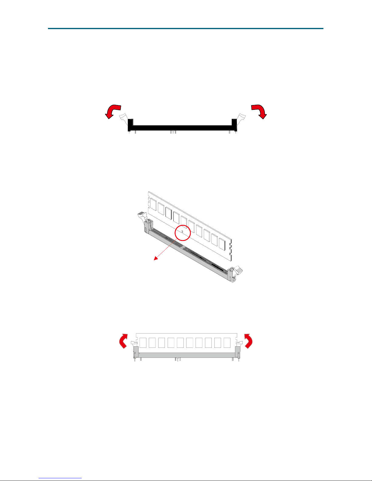
This server board supports 12 DIMM memory slots with 6 channel per CPU.
2�2�1 DIMM Installation
Step 1 Unlock the dimm socket by pressing the retaining clips outward.
Step 2 Insert the memory module into the slot. Make sure that the Dimm notch is
accurately positioned.
Step 3 Close the retaining clips to complete installation.
DIMM n
otch
2�2 System Memory Setup
Page 16
7
Chapter 2. Hardware SetupUrsa User Manual
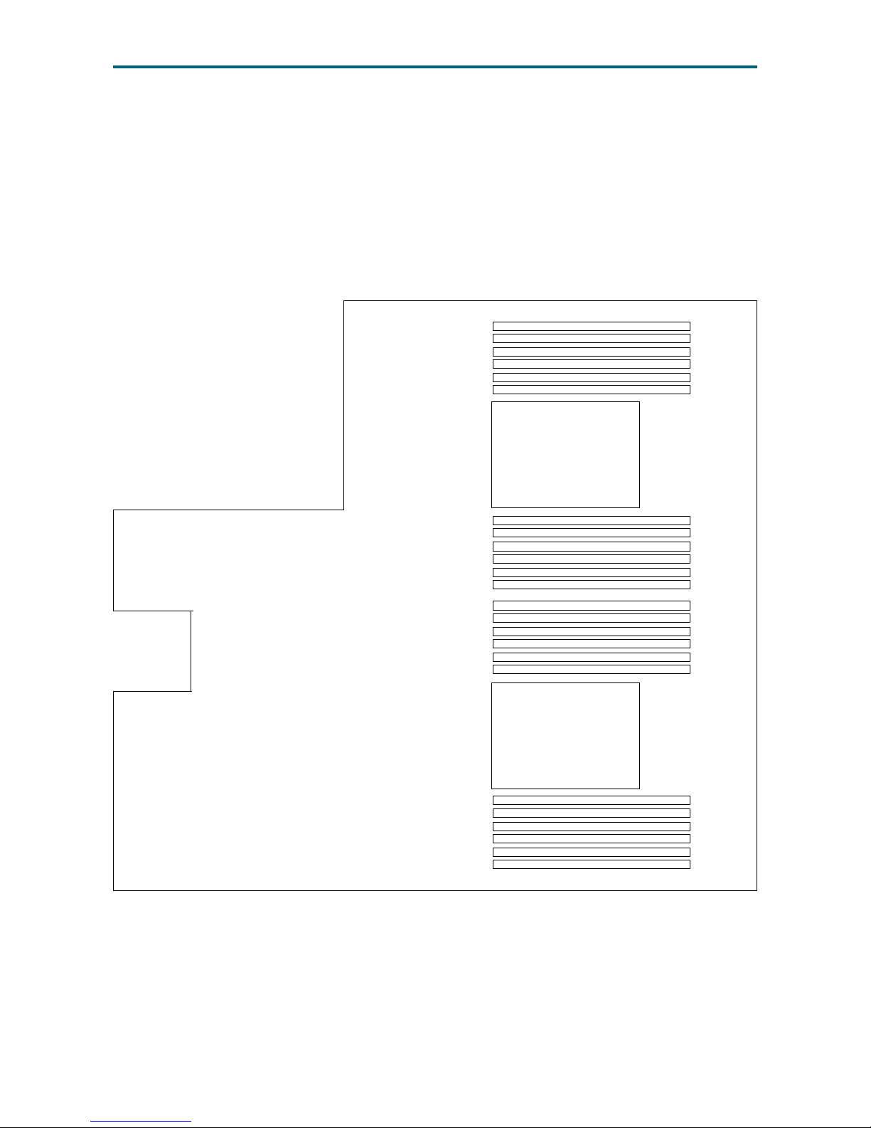
2�2�2 DIMM Location
To ensure satisfactory performance, you need to:
Verify the DIMM type: DDR4 RDIMM/LRDIMM/NVDIMM-N with EEC(Error
Correction Code).
Verify if all of the DIMMs installed are of the same DIMM type to avoid memory
failure and loss of performance speed.
CPU0
CPU1
DIMM C0
DIMM C1
DIMM B0
DIMM B1
DIMM A0
DIMM A1
DIMM D1
DIMM D0
DIMM E1
DIMM E0
DIMM F1
DIMM F0
DIMM C0
DIMM C1
DIMM B0
DIMM B1
DIMM A0
DIMM A1
DIMM D1
DIMM D0
DIMM E1
DIMM E0
DIMM F1
DIMM F0
Page 17
8
Chapter 2. Hardware Setup
Ursa User Manual
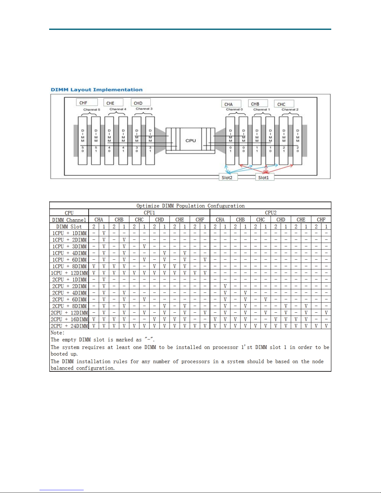
2�2�3 DIMM Slot Installation Order
Populate the DIMM slots according to the suggested order below to ensure a
stable system performance.
Page 18
9
Chapter 3. Motherboard SettingsUrsa User Manual
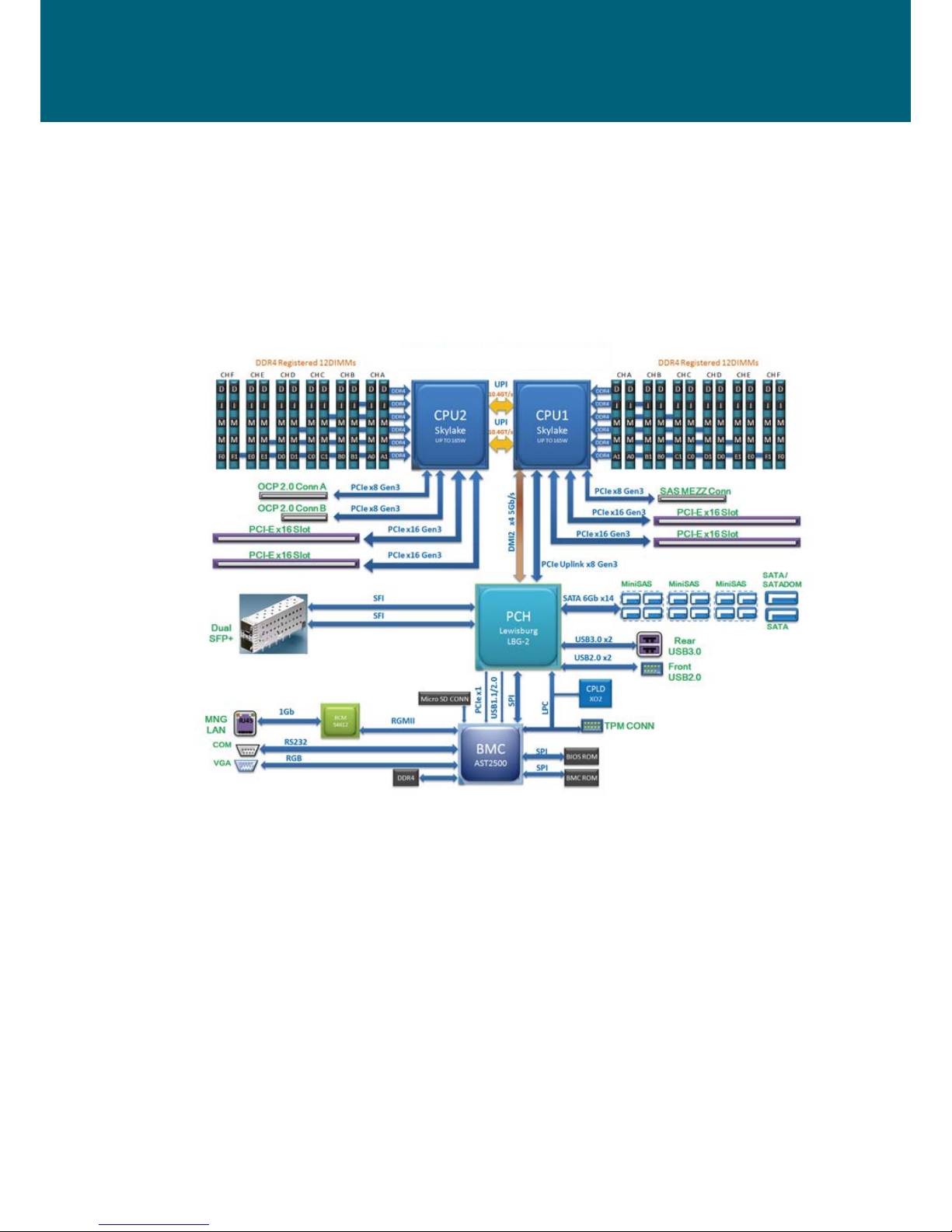
Chapter 3� Motherboard Settings
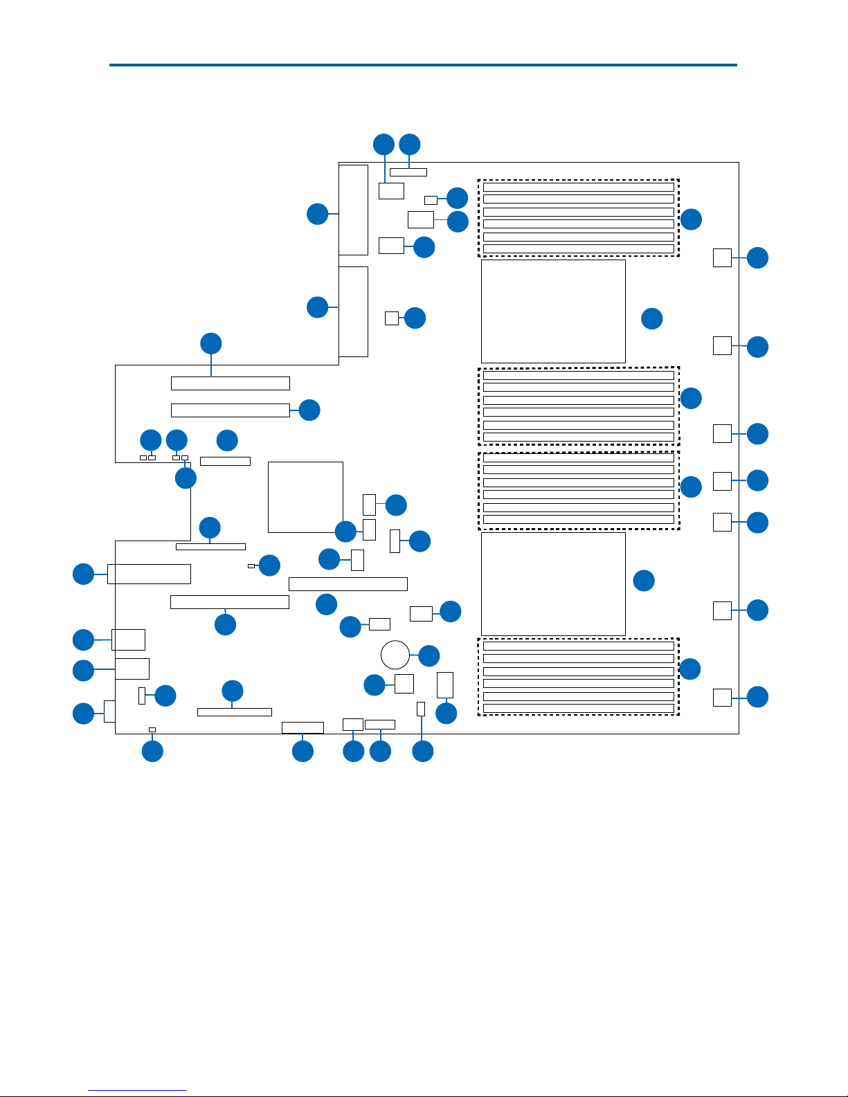
This section provides illustrations that display the internal jumpers, connectors, and
system LED indicators on the Ursa motherboard. The motherboard layout and essential
connectors are listed below for your reference.
3�1 Motherboard Block Diagram
Page 19
10
Chapter 3. Motherboard SettingsUrsa User Manual
3�2 Motherboard Layout
CPU0
CPU1
29
28
27
26
2524
23
22
21
20
19
18
17
16
15
14
13
12
30
31
32
33
34
35
36
37
38
39
41
42
43
44
4546
47
48
49
50
51
1
2
3
4
5
6
7
8
9
1011
40
Page 20

11
Chapter 3. Motherboard SettingsUrsa User Manual
Connector/Jumper/Header Location Connector/Jumper/Header Location
1
VGA Connector J2003
27
SATA/SATADOM
Connector (sSATA 5)
J52
2
Internal Serial Header J2043
28
Processor 1 CPU1
3
Management Port J2002
29
DIMM Slots for
Processor 1
J14, J13, J16, J15,
J18, J17
4
Rear Dual USB Port J2000
30
Fan Connector 6 J103
5
PCI-E X16 Gen3 Slot4 J57
31
Fan Connector 5 J102
6
BIOS CMOS Clear
Jumper
J46
32
DIMM Slots for
Processor 1
J23, J24, J21, J22,
J19, J20
7
10G NIC Ports J86
33
Fan Connector 4 J101
8
NIC OCP 2.0 Connector
A
J25
34
Fan Connector 7 ((for 1U
system)
J2007
9
Manufacture Mode
Jumper
J90
35
DIMM Slots for
Processor 0
J2, J1, J4, J3, J6, J5
10
NMI Jumper J96
36
Fan Connector 3 J100
11
Password Clear
Jumper
J39
37
Processor 0 CPU0
12
PCI-E X16 Gen3 Slot2 J59
38
Fan Connector 2 J99
13
PCI-E X16 Gen3 Slot1 J58
39
Fan Connector 1 J98
14
NIC OCP 2.0 Connector
B
J75
40
DIMM Slots for
Processor 0
J11, J12, J9, J10,
J7, J8
15
PCI-E X16 Gen3 Slot3 J56
41
Internal VROC Connector J2004
16
Slimline Connector
Port 2 (sSATA 0-3)
J70
42
GPU Power Connector J67
17
Slimline Connector
Port 0 (SATA 0-3)
J48
43
TPM Connector J60
18
Slimline Connector
Port 1 (SATA 4-7)
J50
44
Micro-SD Card Socket J88
19
Power Supply
Connector
J84
45
Front Panel USB
Connector
J71
20
Rear 2HDD Backplane
Power Connector
J54
46
Internal USB Port J55
21
GPU Power Connectors
1
J65
47
System Battery BH1
22
GPU Power Connectors
2
J66
48
Front Left-ear Connector J31
23
Power Supply
Connector
J85
49
SATA/SATADOM
Connector (sSATA 4)
J74
24
GPU Power Connectors
3
J64
50
SAS Mezzanine-card
Connector
J26
25
Backplane Power
Connector
J95
51
ME Firmware Recovery
Mode Jumper
J41
26
Rear HDD Backplane
I²C Connector
J34
3�3 Content List
Page 21
12
Chapter 3. Motherboard SettingsUrsa User Manual
3�4 Connetor and Jumper
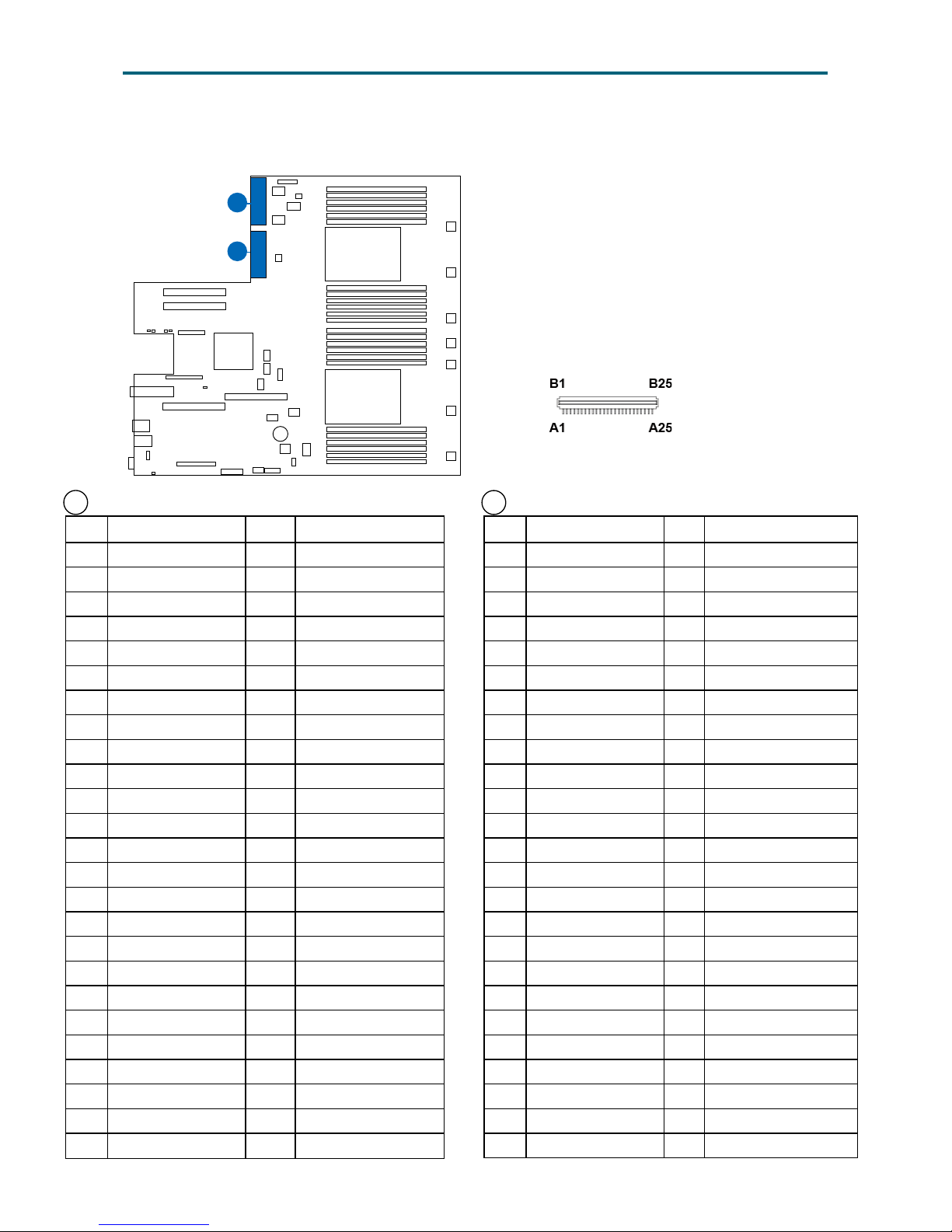
19 Power Supply Connectors: J84
Pin Description Pin Description
A1 Ground B1 Ground
A2 Ground B2 Ground
A3 Ground B3 Ground
A4 Ground B4 Ground
A5 Ground B5 Ground
A6 Ground B6 Ground
A7 Ground B7 Ground
A8 Ground B8 Ground
A9 Ground B9 Ground
A10 +12V B10 +12V
A11 +12V B11 +12V
A12 +12V B12 +12V
A13 +12V B13 +12V
A14 +12V B14 +12V
A15 +12V B15 +12V
A16 +12V B16 +12V
A17 +12V B17 +12V
A18 +12V B18 +12V
A19 I²C PSU SDA B19 PS1 ADD0
A20 I²C PSU SCL B20 PS1 ADD1
A21 PS1 ON12V N B21 +12 Standby
A22 PS1 ALERT N B22 PS CR BUS R
A23 PS1 VSENSE DN B23 PS LOAD SHARE
A24 PS1 VSENSE DP B24 PS1 Present N
A25 PS1 DCOK B25 PS1 ACOK
23 Power Supply Connectors: J85
Pin Description Pin Description
A1 Ground B1 Ground
A2 Ground B2 Ground
A3 Ground B3 Ground
A4 Ground B4 Ground
A5 Ground B5 Ground
A6 Ground B6 Ground
A7 Ground B7 Ground
A8 Ground B8 Ground
A9 Ground B9 Ground
A10 +12V B10 +12V
A11 +12V B11 +12V
A12 +12V B12 +12V
A13 +12V B13 +12V
A14 +12V B14 +12V
A15 +12V B15 +12V
A16 +12V B16 +12V
A17 +12V B17 +12V
A18 +12V B18 +12V
A19 I²C PSU SDA B19 PS2 ADD0
A20 I2C PSU SCL B20 PS2 ADD1
A21 PS2 ON12V N B21 +12 Standby
A22 PS2 ALERT N B22 PS CR BUS R
A23 PS2 VSENSE DN B23 PS LOAD SHARE
A24 PS2 VSENSE DP B24 PS2 Present N
A25 PS2 DCOK B25 PS2 ACOK
CPU0
CPU1
23
19
5
3�4�1 Connector
Page 22
13
Chapter 3. Motherboard SettingsUrsa User Manual
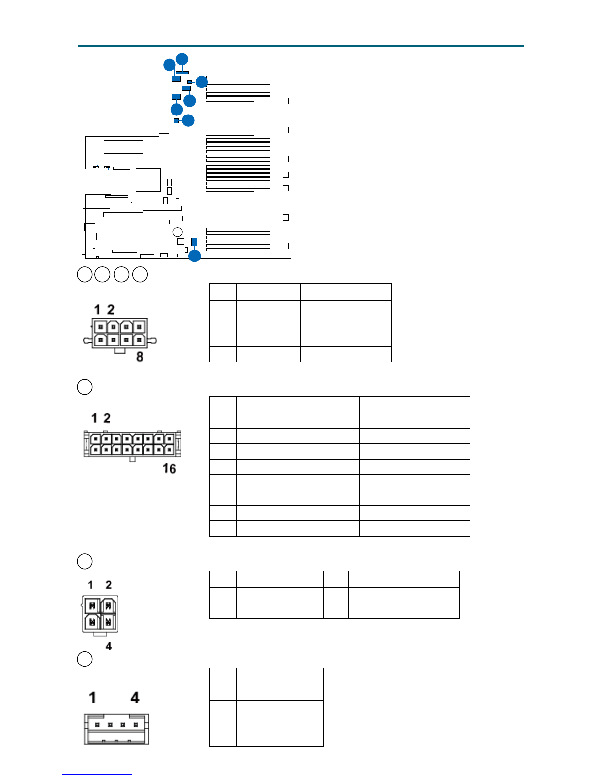
24 21 22 42 GPU Power Connectors (J64, J65, J66, J67)
Pin Description Pin Description
1 Ground 5 +12V
2 Ground 6 +12V
3 Ground 7 +12V
4 Ground 8 +12V
25 Backplane Power Connector (J95)
Pin Description Pin Description
1 Ground 9 +12V
2 Ground 10 +12V
3 Ground 11 +12V
4 Ground 12 +12V
5 Ground 13 +12V
6 Ground 14 +12V
7 Ground 15 RST_I2C_HDDBP_N
8 I2C_HDDBP_SDA 16 I2C_HDDBP_SCL
20 Rear 2HDD Backplane Power Connector (J54)
Pin Description Pin Description
1 +12V 3 Ground
2 +5V 4 Ground
26 Rear HDD Backplane I²C Connector (J34)
Pin Description
1 I²C_GPU_SCL
2 I²C_GPU_SDA
3 Ground
4 NC
CPU0
CPU1
5
42
24
22
21
25
20
26
Page 23
14
Chapter 3. Motherboard SettingsUrsa User Manual
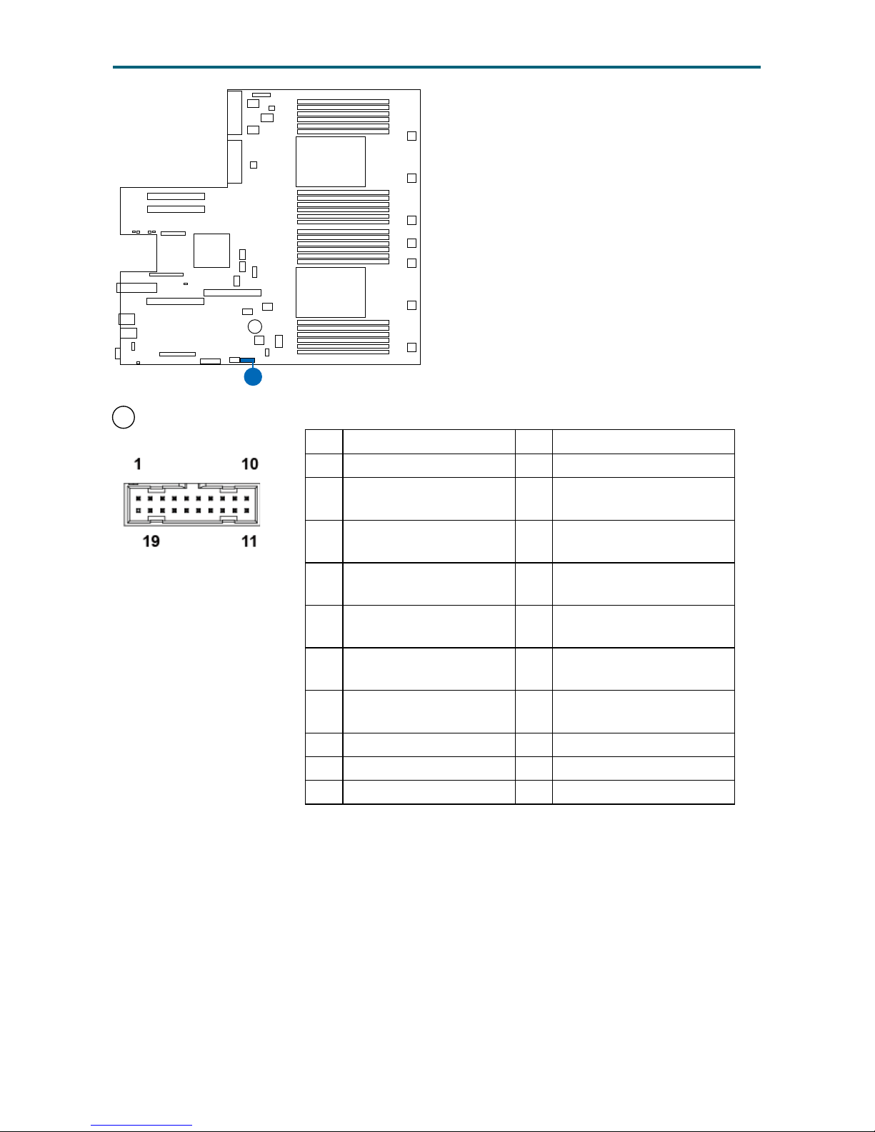
45 Front Panel USB Connector (J71)
Pin Description Pin Description
1 +5V_USB3_FRONT1
2 PCH_USB3_RX_P4_
ESD_DN
19 PSV_USB3_FRONT2
3 PCH_USB3_RX_P4_
ESD_DP
18 PCH_USB3_RX_P5_
ESD_DN
4 Ground 17 PCH_USB3_RX_P5_
ESD_DP
5 PCH_USB3_TX_P4_
ESD_DN
16 Ground
6 PCH_USB3_TX_P4_
ESD_DP
15 PCH_USB3_TX_P5_
ESD_DN
7 Ground 14 PCH_USB3_TX_P5_
ESD_DP
8 PCH_USB2_ P4_L_DN 13 Ground
9 PCH_USB2_ P4_L_DP 12 PCH_USB2_ P5_L_DN
10 NC 11 PCH_USB2_ P5_L_DP
CPU0
CPU1
5
45
Page 24
15
Chapter 3. Motherboard SettingsUrsa User Manual
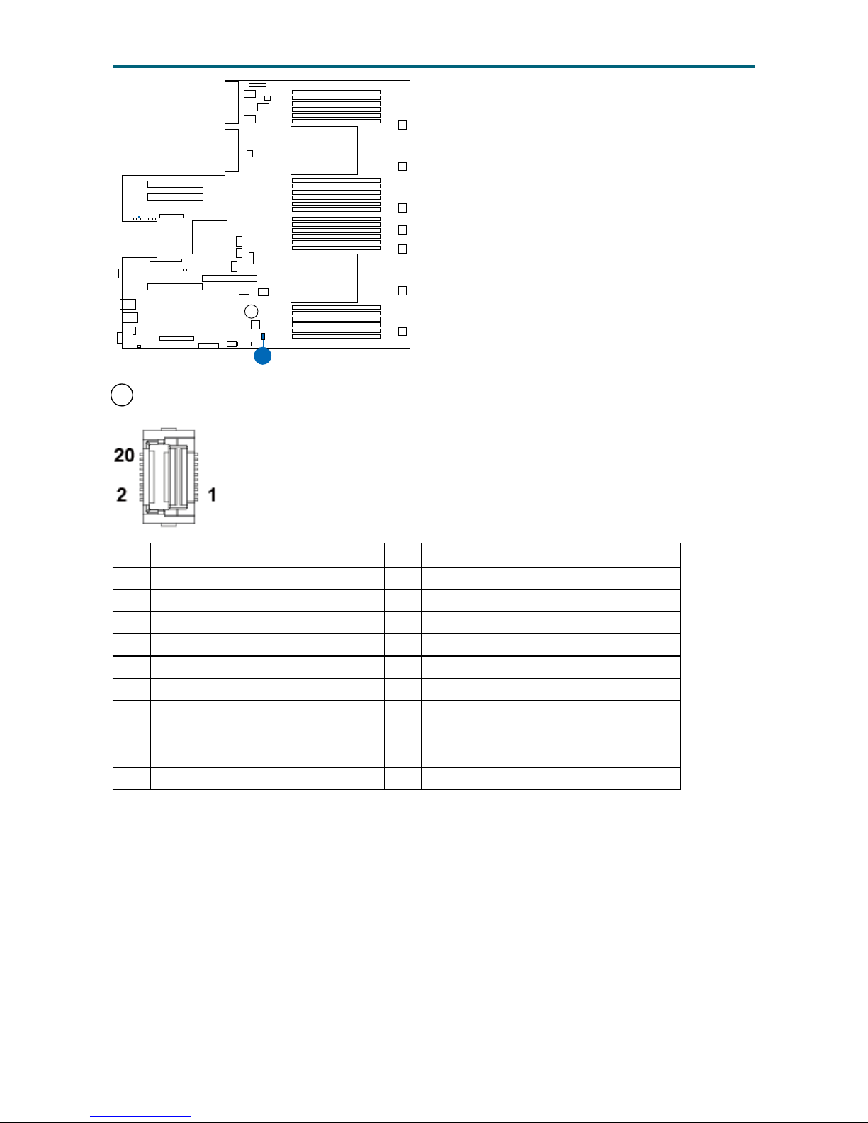
43 TPM Connector (J60)
Pin Description Pin Description
1 LPC_TPM_Module_AD<0> 2 TPM_Vendor_ID1
3 TPM_PRSNT_N 4 LPC_AD_1
5 LPC_FRAME_TPM_Module_N 6 LPC_SERIRQ
7 Ground 8 +3V3
9 Clock_33M_PCH_LPC_TPM5% 10 RST_LPC_TPM_Module_N
11 Ground 12 LPC_TPM_Module_AD<2>
13 +3V3_STBY 14 Ground
15 Ground 16 LPC_TPM_Module_AD<3>
17 CLK_32K_SUSCLK_TPM_R 18 TPM_PACCESS
19 TPM_VENDOR_ID0 20 TPM_LPCPD_R_N
CPU0
CPU1
5
43
Page 25
16
Chapter 3. Motherboard SettingsUrsa User Manual
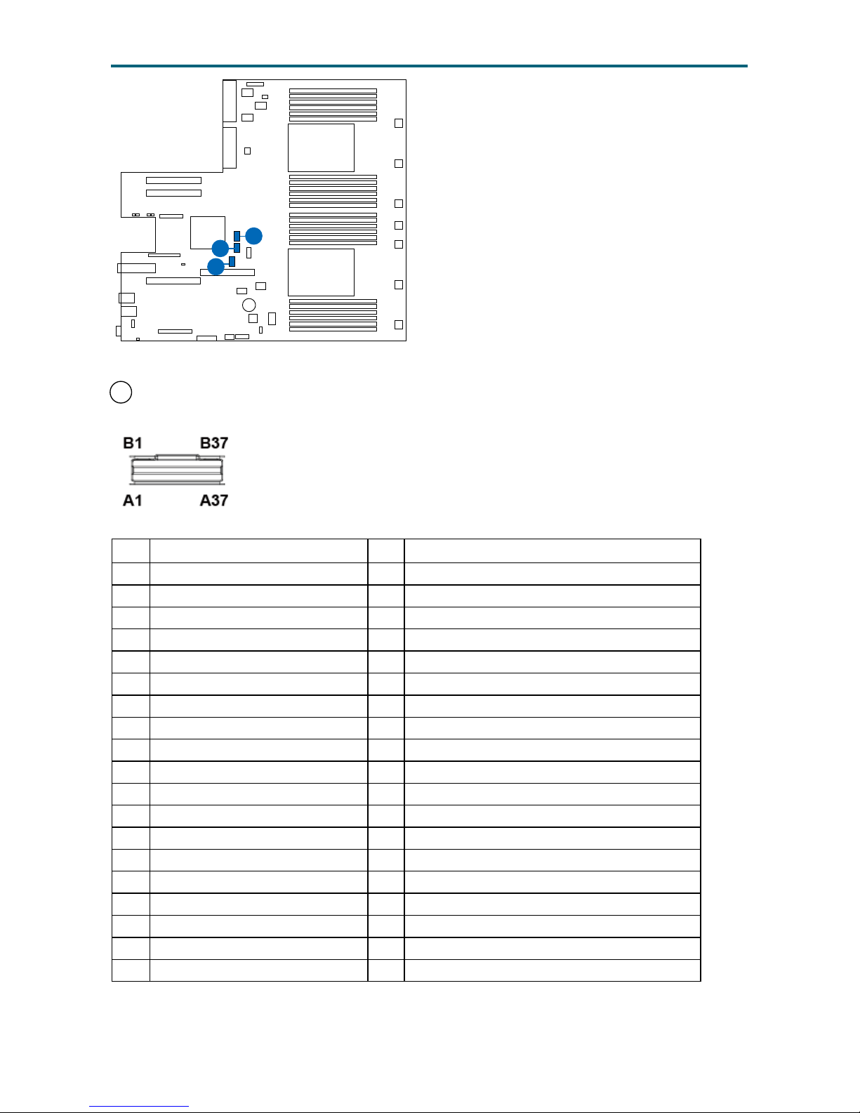
17 Slimline Connector 0 (J48)
Pin Description Pin Description
A1 Ground B1 Ground
A2 PCH_SATA_RX_P0_C_DP B2 PCH_SATA_TX_P0_C_DP
A3 PCH_SATA_RX_P0_C_DN B3 PCH_SATA_TX_P0_C_DN
A4 Ground B4 Ground
A5 PCH_SATA_RX_P1_C_DP B5 PCH_SATA_TX_P1_C_DP
A6 PCH_SATA_RX_P1_C_DN B6 PCH_SATA_TX_P1_C_DN
A7 Ground B7 Ground
A8 SGPIO_SATA_DATA0 B8 SGPIO_SATA_CLOCK
A9 TP_SATA0_RSVD_A9 B9 SGPIO_SATA_LOAD
A10 Ground B10 Ground
A11 TP_SATA0_RSVD_A11 B11 TP_SATA0_RSVD_B11
A12 TP_SATA0_RSVD_A12 B12 NC
A13 Ground B13 Ground
A14 PCH_SATA_RX_P2_C_DP B14 PCH_SATA_TX_P2_C_DP
A15 PCH_SATA_RX_P2_C_DN B15 PCH_SATA_TX_P2_C_DN
A16 Ground B16 Ground
A17 PCH_SATA_RX_P3_C_DP B17 PCH_SATA_TX_P3_C_DP
A18 PCH_SATA_RX_P3_C_DN B18 PCH_SATA_TX_P3_C_DN
A19 Ground B19 Ground
CPU0
CPU1
5
26
45
16
17
18
Page 26
17
Chapter 3. Motherboard SettingsUrsa User Manual
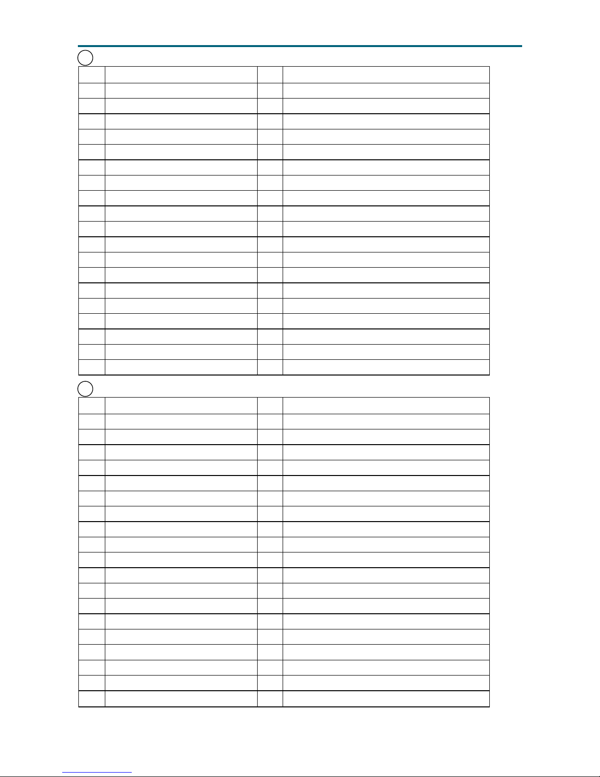
18 Slimline Connector 1 (J50)
Pin Description Pin Description
A1 Ground B1 Ground
A2 PCH_SATA_RX_P4_C_DP B2 PCH_SATA_TX_P4_C_DP
A3 PCH_SATA_RX_P4_C_DN B3 PCH_SATA_TX_P4_C_DN
A4 Ground B4 Ground
A5 PCH_SATA_RX_P5_C_DP B5 PCH_SATA_TX_P5_C_DP
A6 PCH_SATA_RX_P5_C_DN B6 PCH_SATA_TX_P5_C_DN
A7 Ground B7 Ground
A8 SGPIO_SATA_DATA1 B8 SGPIO_SATA_CLOCK
A9 TP_SATA1_RSVD_A9 B9 SGPIO_SATA_LOAD
A10 Ground B10 Ground
A11 TP_SATA1_RSVD_A11 B11 TP_SATA1_RSVD_B11
A12 TP_SATA1_RSVD_A12 B12 NC
A13 Ground B13 Ground
A14 PCH_SATA_RX_P6_C_DP B14 PCH_SATA_TX_P6_C_DP
A15 PCH_SATA_RX_P6_C_DN B15 PCH_SATA_TX_P6_C_DN
A16 Ground B16 Ground
A17 PCH_SATA_RX_P7_C_DP B17 PCH_SATA_TX_P7_C_DP
A18 PCH_SATA_RX_P7_C_DN B18 PCH_SATA_TX_P7_C_DN
A19 Ground B19 Ground
16 Slimline Connector 2 (J70)
Pin Description Pin Description
A1 Ground B1 Ground
A2 PCH_SATA_RX_S0_C_DP B2 PCH_SATA_TX_S0_C_DP
A3 PCH_SATA_RX_S0_C_DN B3 PCH_SATA_TX_S0_C_DN
A4 Ground B4 Ground
A5 PCH_SATA_RX_S1_C_DP B5 PCH_SATA_TX_S1_C_DP
A6 PCH_SATA_RX_S1_C_DN B6 PCH_SATA_TX_S1_C_DN
A7 Ground B7 Ground
A8 SGPIO_SSATA_DATA0 B8 SGPIO_SSATA_CLOCK
A9 TP_SSATA_RSVD_A9 B9 SGPIO_SSATA_LOAD
A10 Ground B10 Ground
A11 TP_SSATA_RSVD_A11 B11 TP_SSATA_RSVD_B11
A12 TP_SSATA_RSVD_A12 B12 NC
A13 Ground B13 Ground
A14 PCH_SATA_RX_S2_C_DP B14 PCH_SATA_TX_S2_C_DP
A15 PCH_SATA_RX_S2_C_DN B15 PCH_SATA_TX_S2_C_DN
A16 Ground B16 Ground
A17 PCH_SATA_RX_S3_C_DP B17 PCH_SATA_TX_S3_C_DP
A18 PCH_SATA_RX_S3_C_DN B18 PCH_SATA_TX_S3_C_DN
A19 Ground B19 Ground
Page 27
18
Chapter 3. Motherboard SettingsUrsa User Manual
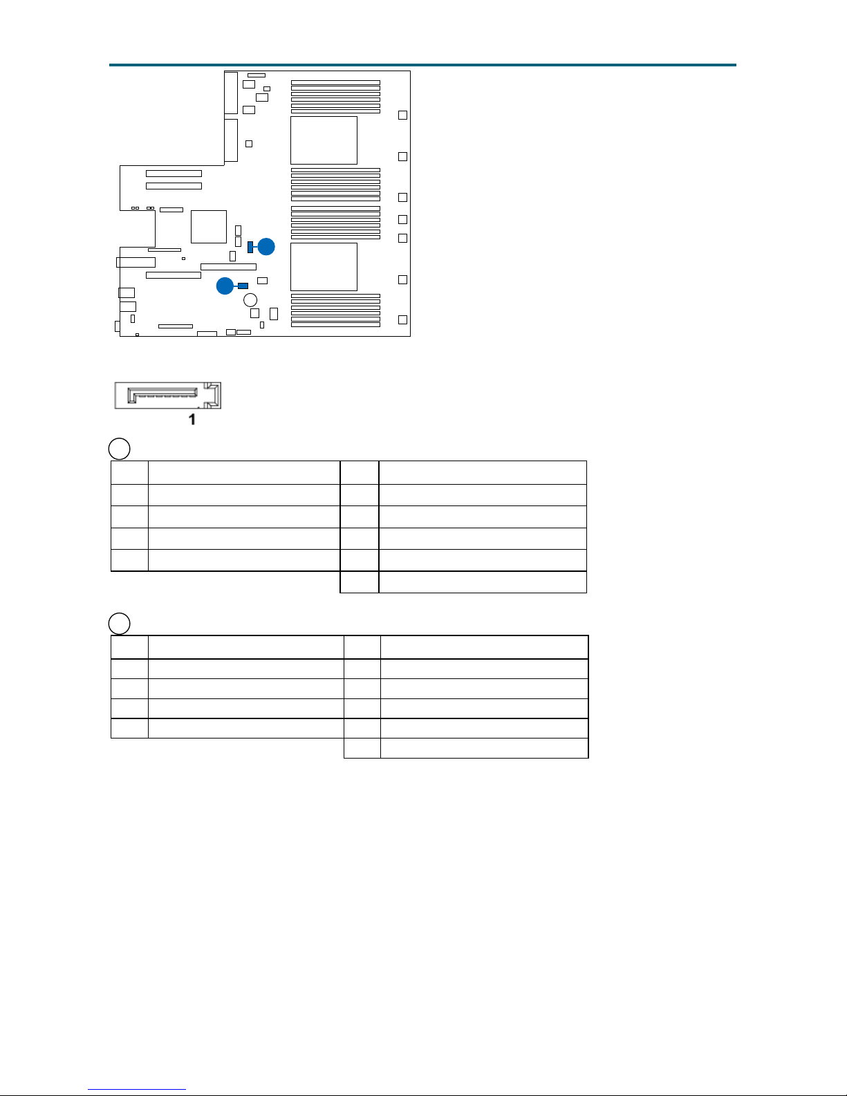
27 SATA/SATADOM Connectors(sSATA 5) (J52)
Pin Description Pin Description
1 Ground 5 PCH_SATA_RX_S5_C_DN
2 PCH_SATA_TX_S5_C_DP 6 PCH_SATA_RX_S5_C_DP
3 PCH_SATA_TX_S5_C_DN 7 +5V_SATADOM_2
4 Ground 8 +5V
9 Ground
49 SATA/SATADOM Connectors(sSATA 4) (J74)
Pin Description Pin Description
1 Ground 5 PCH_SATA_RX_S4_C_DN
2 PCH_SATA_TX_S4_C_DP 6 PCH_SATA_RX_S4_C_DP
3 PCH_SATA_TX_S4_C_DN 7 +5V_SATADOM_1
4 Ground 8 +5V
9 Ground
CPU0
CPU1
5
26
45
49
27
Page 28
19
Chapter 3. Motherboard SettingsUrsa User Manual
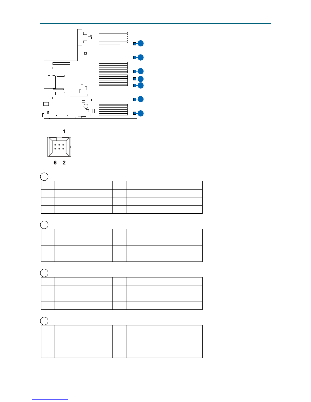
39 Fan Connectors 1 (J98)
Pin Description Pin Description
1 Ground 4 BMC_FAN_PWM_1_R
2 PU_FAN_ID_1 5 PU_FAN_INSTALL_1_N
3 BMC_FAIL_1_R 6 +12V
38 Fan Connectors 2 (J99)
Pin Description Pin Description
1 Ground 4 BMC_FAN_PWM_2_R
2 PU_FAN_ID_2 5 PU_FAN_INSTALL_2_N
3 BMC_FAIL_2_R 6 +12V
36 Fan Connectors 3 (J100)
Pin Description Pin Description
1 Ground 4 BMC_FAN_PWM_3_R
2 PU_FAN_ID_3 5 PU_FAN_INSTALL_3_N
3 BMC_FAIL_3_R 6 +12V
33 Fan Connectors 4 (J101)
Pin Description Pin Description
1 Ground 4 BMC_FAN_PWM_4_R
2 PU_FAN_ID_4 5 PU_FAN_INSTALL_4_N
3 BMC_FAIL_4_R 6 +12V
CPU0
CPU1
5
26
45
27
30
31
33
34
36
38
39
Page 29
20
Chapter 3. Motherboard SettingsUrsa User Manual
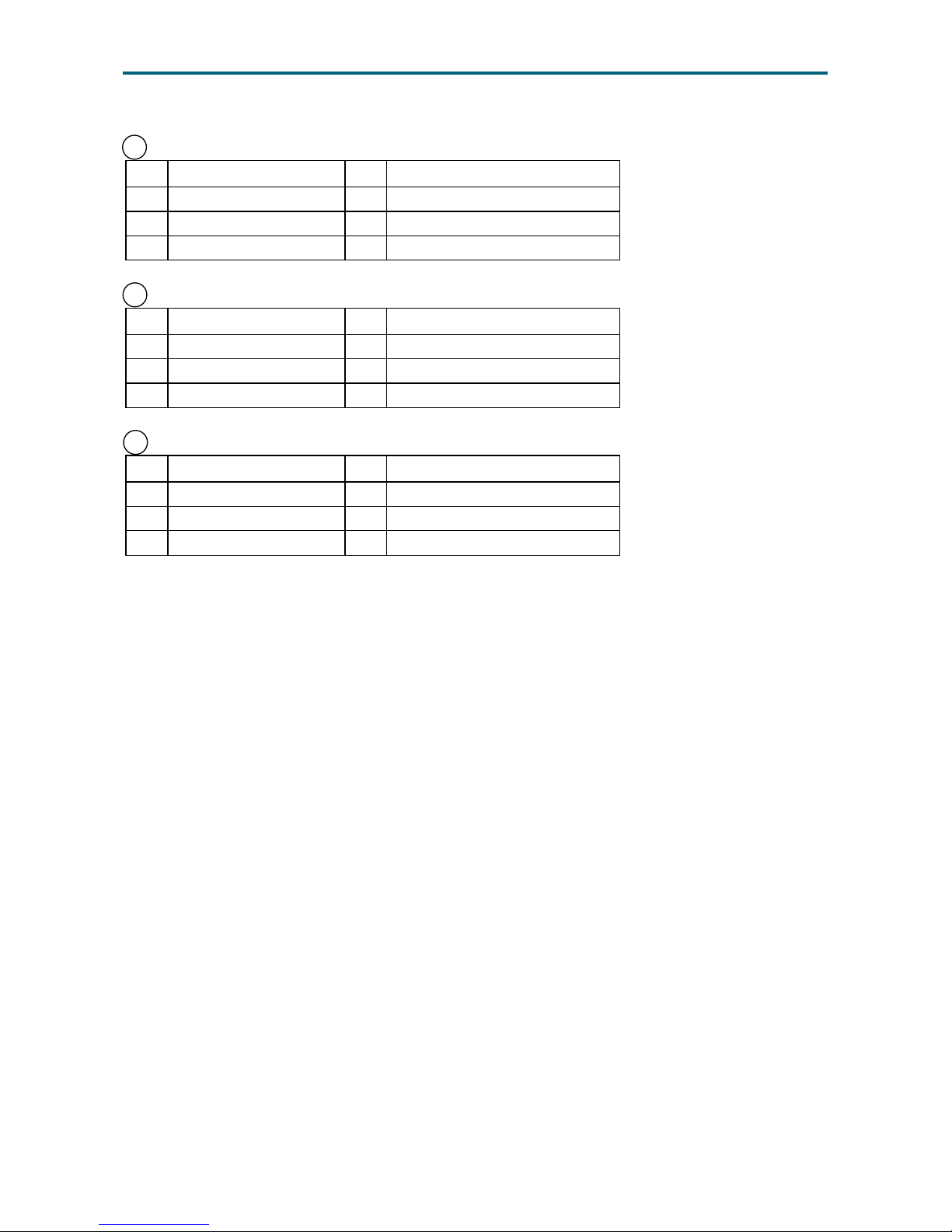
31 Fan Connectors 5 (J102)
Pin Description Pin Description
1 Ground 4 BMC_FAN_PWM_5_R
2 PU_FAN_ID_5 5 PU_FAN_INSTALL_5_N
3 BMC_FAIL_5_R 6 +12V
30 Fan Connectors 6 (J103)
Pin Description Pin Description
1 Ground 4 BMC_FAN_PWM_6_R
2 PU_FAN_ID_6 5 PU_FAN_INSTALL_6_N
3 BMC_FAIL_6_R 6 +12V
34 Fan Connectors 7 (J2007)
Pin Description Pin Description
1 Ground 4 BMC_FAN_PWM_7_R
2 PU_FAN_ID_7 5 PU_FAN_INSTALL_7_N
3 BMC_FAIL_7_R 6 +12V
Page 30
21
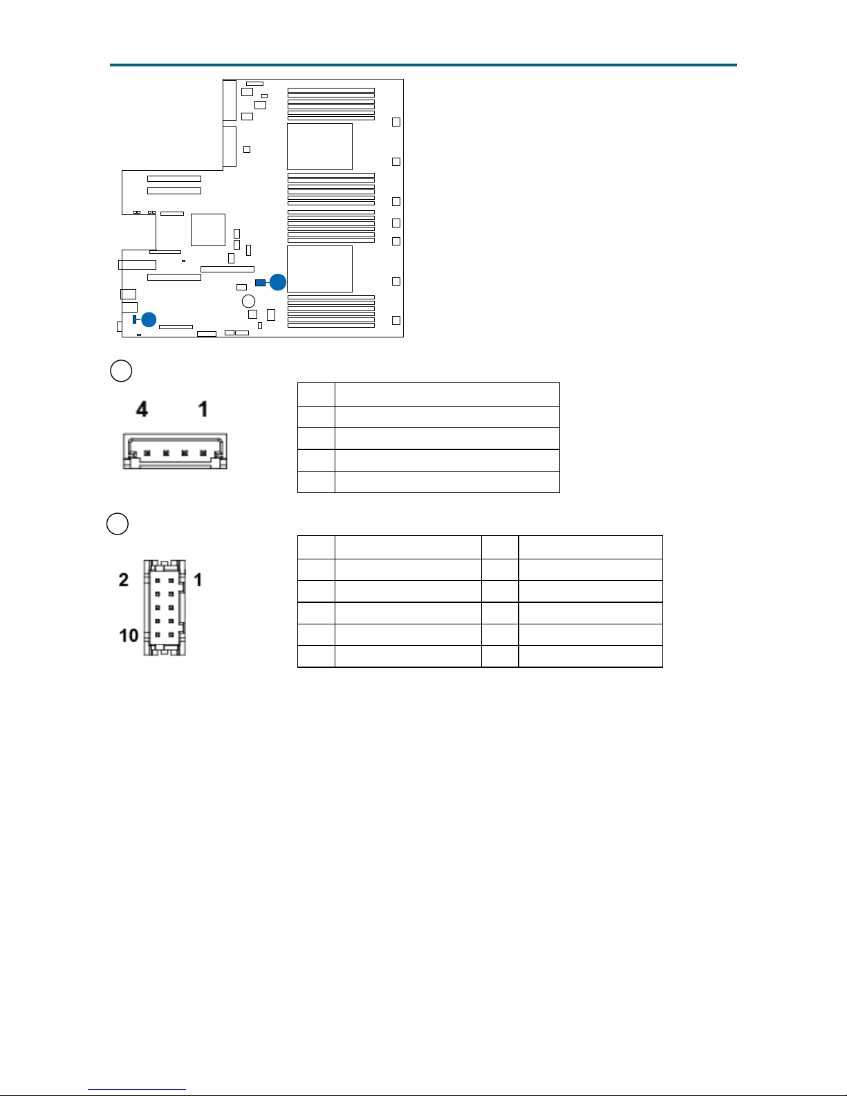
Chapter 3. Motherboard SettingsUrsa User Manual
41 Internal VROC Connector (J2004)
Pin Description
1 Ground
2 PU_VROC_CONN_PIN2
3 Ground
4 FM_PCH_SATA_RAID_KEY_R
2 Internal Serial Header (J2043)
Pin Description Pin Description
1 COM1_RES_DCD 2 COM1_RES_RX_N
3 COM1_RES_TX_N 4 COM1_RES_DTR
5 Ground 6 COM1_RES_DSR
7 COM1_RES_RTS 8 COM1_RES_CTS
9 COM1_RES_RI 10 Ground
CPU0
CPU1
5
26
45
27
41
2
Page 31
22
Chapter 3. Motherboard SettingsUrsa User Manual
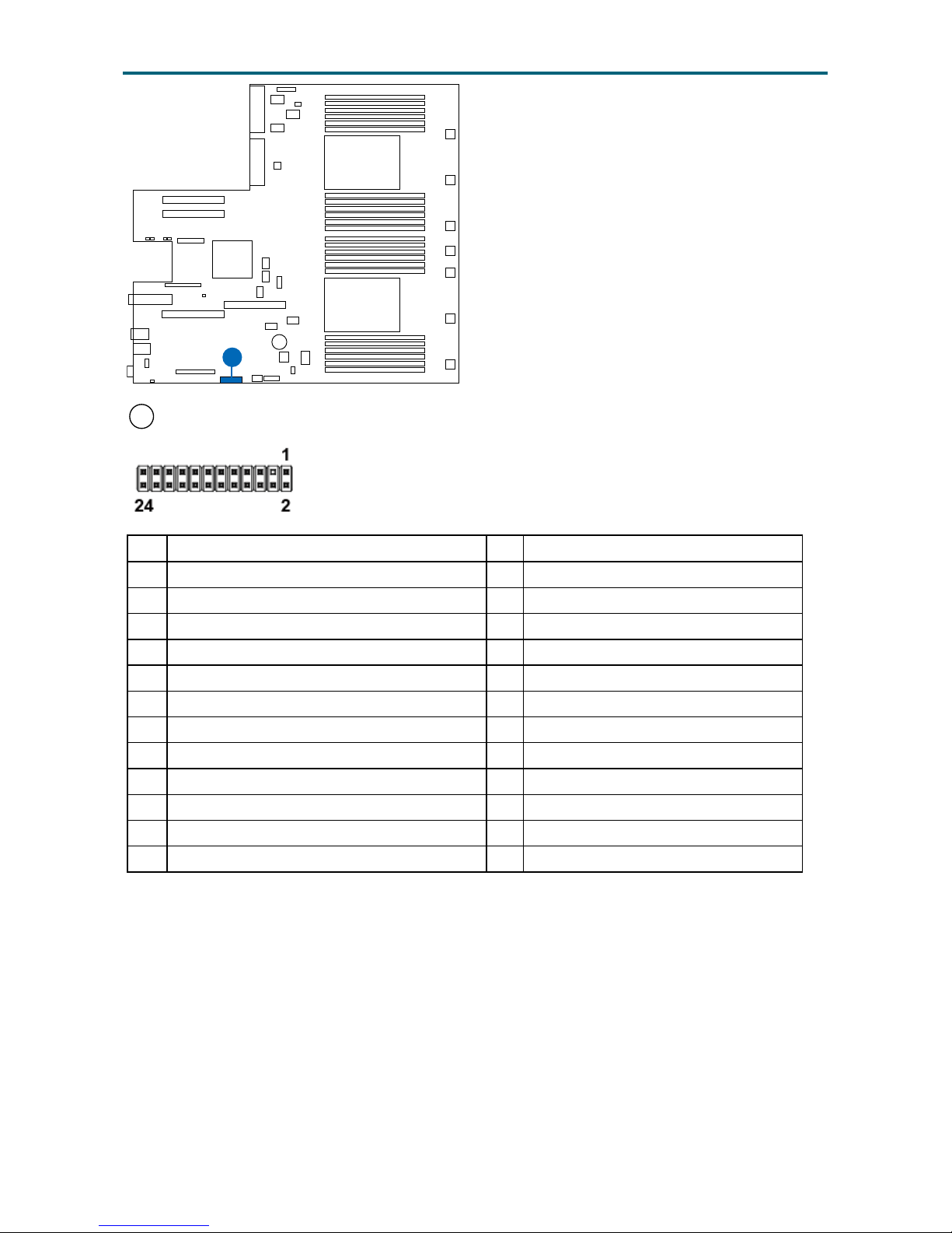
48 Front Left-ear Connector (J31)
Pin Description Pin Description
1 LED_PWR_AMB_CPLD2SSIFP_R_N 2 +3V_Standby_FP
3 4 +5V_Standby_FP
5 LED_PWR_GRN_CPLD2SSIFP_R_N 6 LED_UID_CPLD2SSIFP_R_N
7 +3V_FP 8 LED_HLTH_GRN_CPLD2SSIFP_R
9 DC_LED_HDD_ACT_CPLD2SSIFP_R_N 10 LED_HLTH_RED_CPLD2SSIFP_R
11 BTN_PWRON_SSIFP2CPLD_N 12 +3V_Standby_FP
13 Ground 14 LED_NIC0_LINK_ACT_R_N
15 BTN_RST_SSIFP2CPLD_N 16 I2C_G6_PSU_CTRL_SDA
17 Ground 18 I2C_G6_PSU_CTRL_SCL
19 BTN_UID_SSIFP2CPLD_N 20 DC_Intruder_HDR
21 +5V_Standby_FP 22 +3V_Standby_FP
23 DC_BTN_NMI_SSIFP2CPLD_N 24 LED_NIC1_LINK_ACT_R_N
CPU0
CPU1
5
26
45
27
48
Page 32
23
Chapter 3. Motherboard SettingsUrsa User Manual
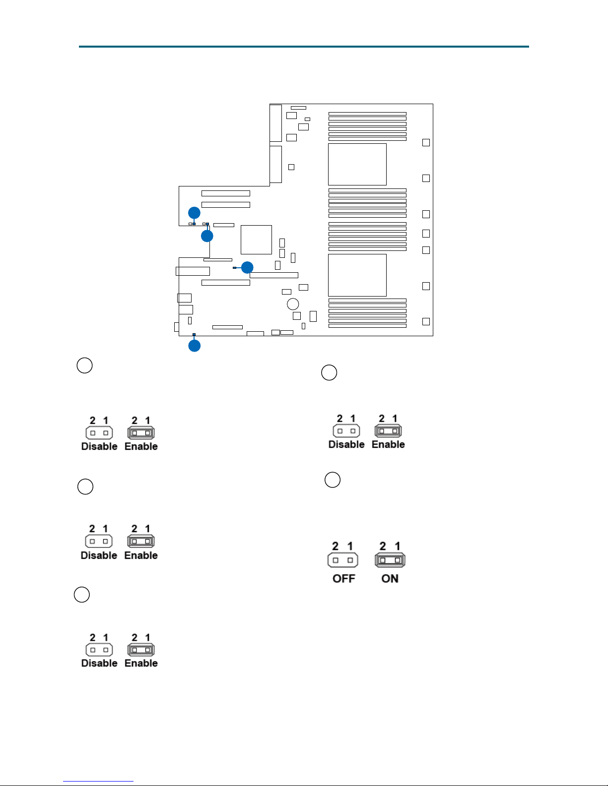
3�4�2 Jumper
51 ME Firmware Recovery Mode Jumper
Setting (J41)
Function: ME Recovery
11 Password Clear Jumper Setting (J39)
Function: Password clear
6 BIOS CMOS Clear Jumper Setting (J46)
Function: BIOS CMOS Clear Jumper Function
9 Manufacturing Mode Jumper Setting
(J90)
Function: Manufacturing Mode
10 Non-maskable Interrupt Switch
Jumper Setting (J96)
Function: Non-maskable interrupt
switch
CPU0
CPU1
5
26
45
51
11
6
9
Page 33
24
Chapter 4. BIOS Conguration SettingsUrsa User Manual
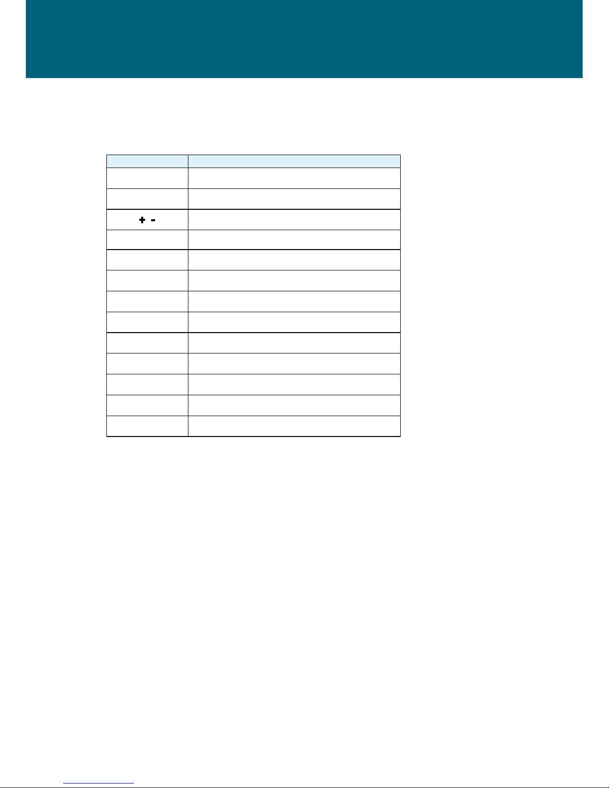
4�1 Navigation Keys
The navigation keys are listed below.
Function Key Description
, , ,
Select item.
Enter Select and enter sub-screen.
+ , - Modify selected option.
F1 General help.
F2 Previous Value.
F3 Optimized defaults.
F4 Save & Exit.
F5, F6 Change values.
F7 Discard Change and Exit.
F9 Load Optimal Default for all values.
F10 Save changes and exit.
F12 Print Screen.
Esc
Exit the current menu screen.
Chapter 4. BIOS Conguration Settings
Page 34
25
Chapter 4. BIOS Conguration SettingsUrsa User Manual
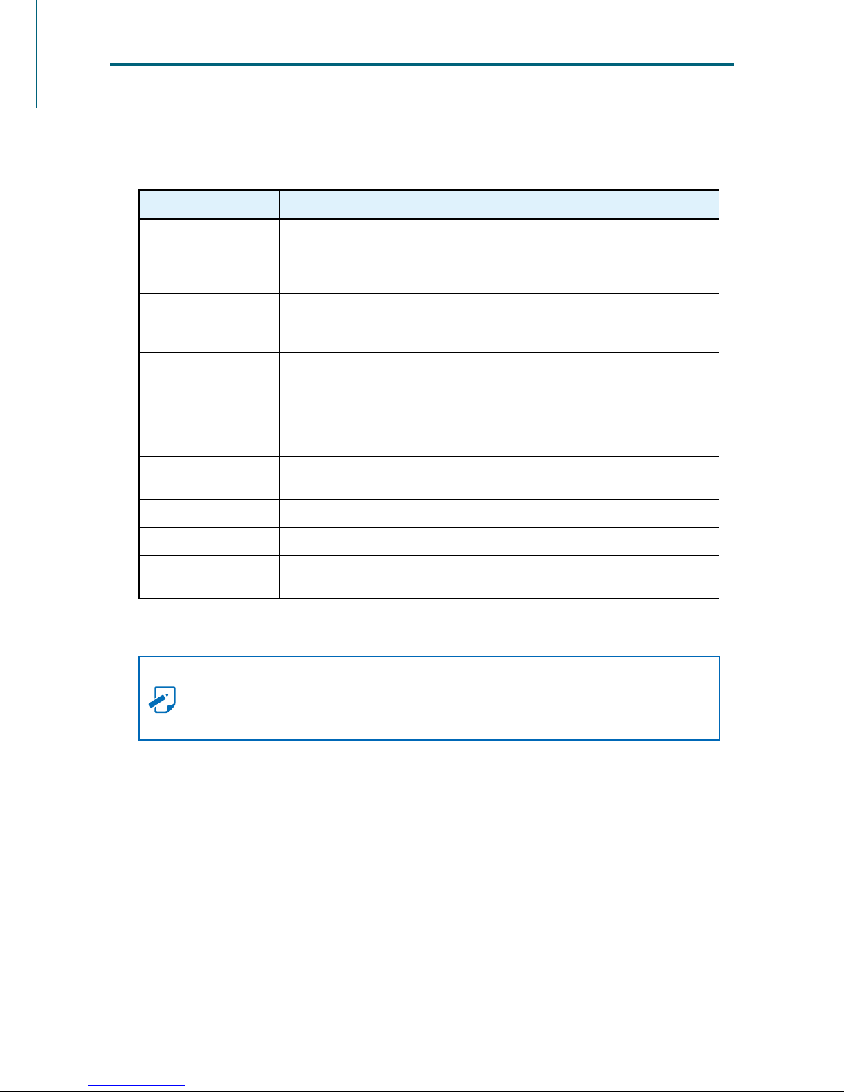
Press and to select the options of the menu bar.
Press Enter to access the option screen.
Menu Description
Main
Displays system information such as CPU bus speed, system memory
speed, total installed memory, current EFI language, and system date &
time.
Advanced
Allows conguration of advanced system settings such as ACPI features,
boot, and chipset conguration.
Platform
Conguration
Allows conguration of platform settings such as PCH, miscellaneous,
and server ME conguration.
Socket Conguration
Allows conguration of socket settings such as processor, Common
RefCode, UPI, and memory congurtaion.
BMC
Allows conguration of socket settings such as BMC network
conguration.
Security Sets passwords and security functions.
Boot Sets boot options such as Quick Boot or USB Boot.
Save and Exit
Allows user to save or discard BIOS changes, and load optimal or custom
default settings.
NOTE
The following pages provide the details of BIOS menu. Please be
noticed that the BIOS menu are continually changing due to the BIOS updating.
The BIOS menu provided are the most updated ones when this manual is written.
4�2 BIOS Menu
Page 35
26
Chapter 4. BIOS Conguration SettingsUrsa User Manual
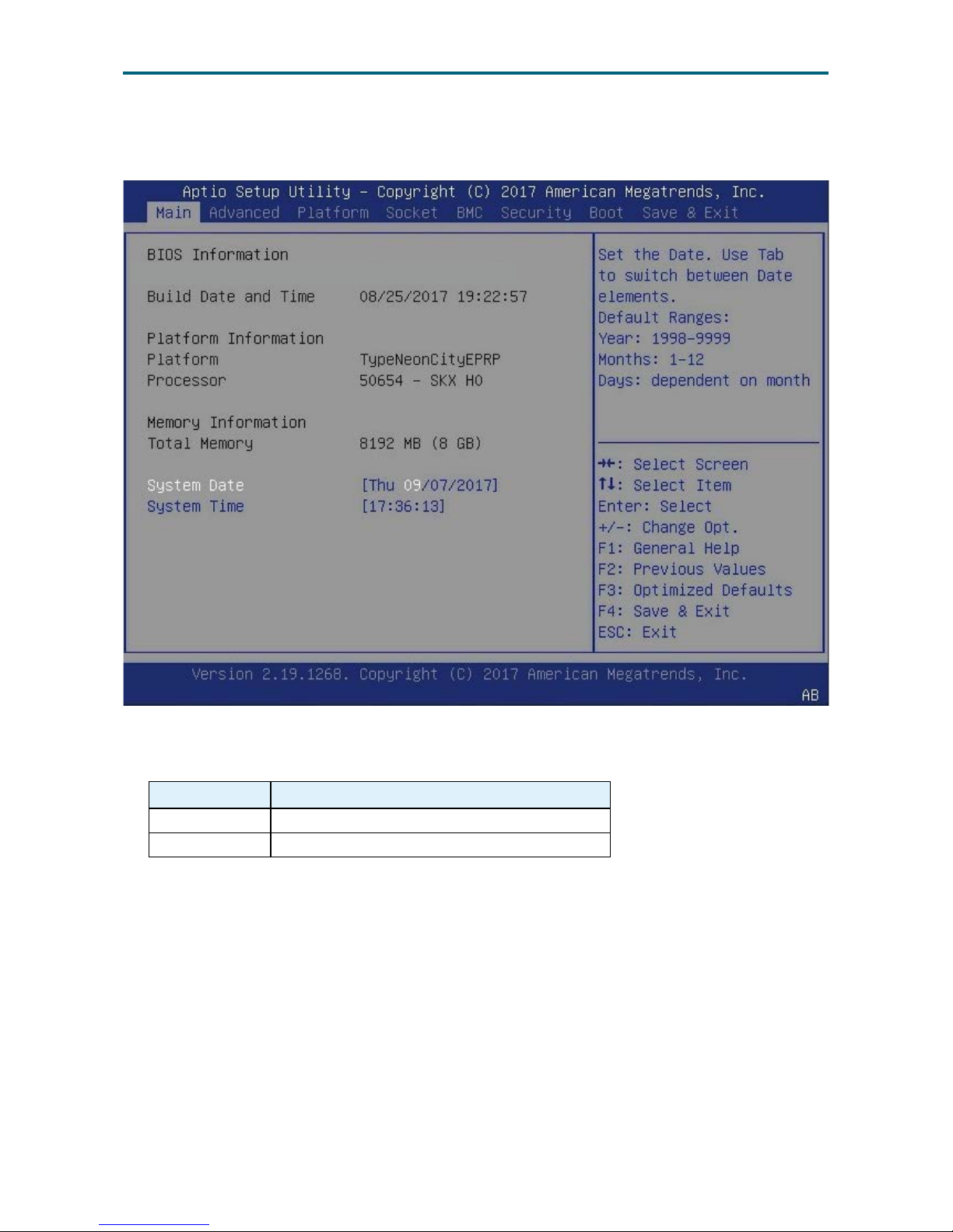
4�3�1 Main
Main Option Key:
Option Key Description
System time Congures current time.
System date Congures current date.
4�3 Main
Page 36
27
Chapter 4. BIOS Conguration SettingsUrsa User Manual
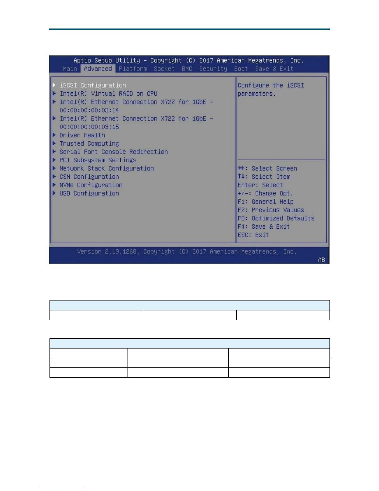
Advanced Option Key:
4.4.1 iSCSI Conguration
iSCSI Conguration
Add an Attempt Delete Attempts Change Attempt Order
4�4�2 Trusted Computing
Trusted Computing
Security Device Support Enable Disable
TPM State Enable Disable
Pending Operation Enable Disable
4�4 Advanced
Page 37
28
Chapter 4. BIOS Conguration SettingsUrsa User Manual
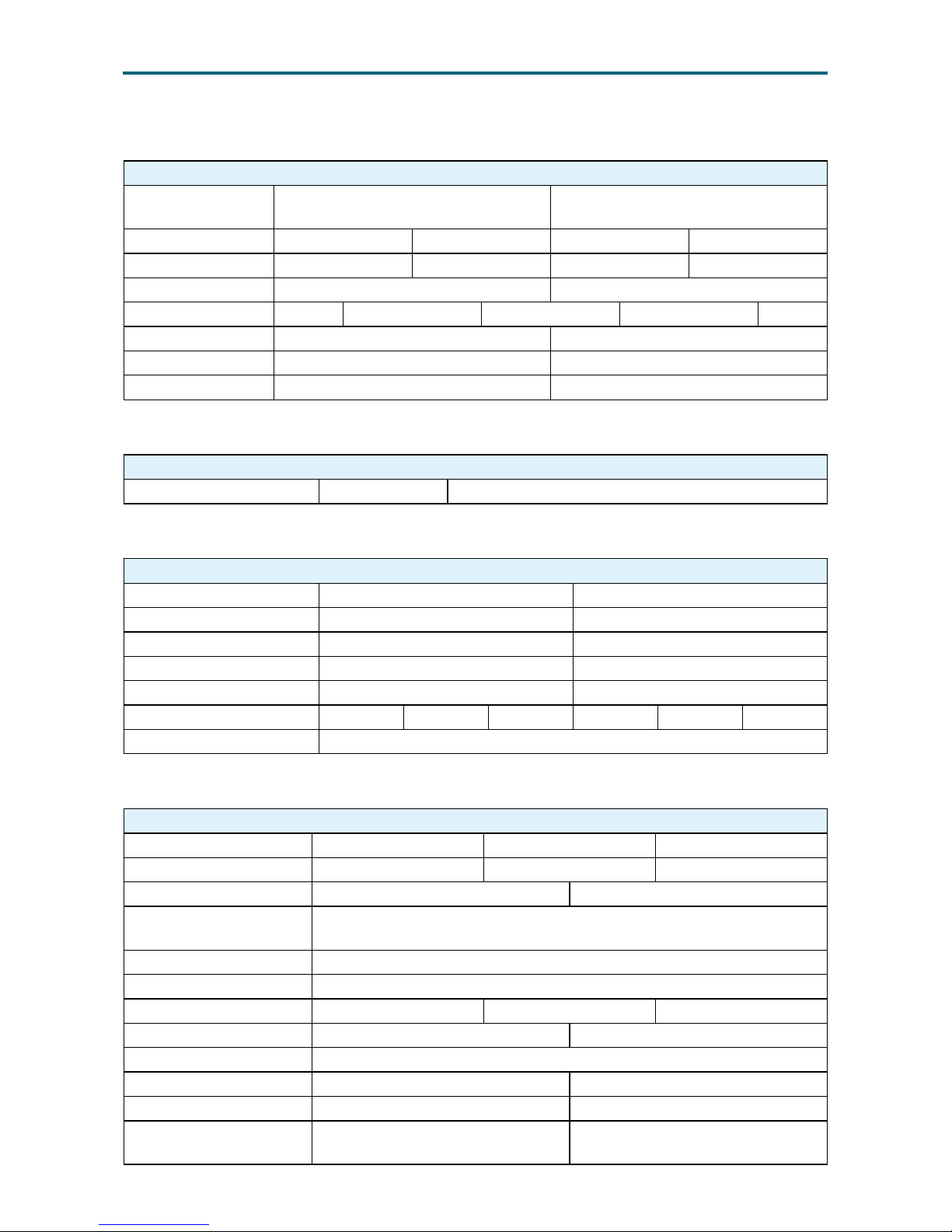
4�4�3 Serial Port Console Redirection
Serial Port Console Redirection
Console
Redirection
Enable Disable
Terminal Type VT100 VT100+ VT-UTF8 ANSI
Bits per second 9600 19200 57600 115200
Data Bits 7 8
Parity None Even Odd Mark Space
Stop Bits 1 2
Flow Control None Hardware RTS/CTS
EMS Enable Disable
4�4�4 PCI Subsystem Settings
PCI Subsystem Settings
SR-IOV Support Enable Disable
4.4.5 Network Stack Conguration
Network Stack Conguration
Network Stack Enable Disable
Ipv4 PXE Support Enable Disable
Ipv4 HTTP Support Enable Disable
Ipv6 PXE Support Enable Disable
Ipv6 HTTP Support Enable Disable
PXE boot wait time 0 1 2 3 4 5
Media detect count 0~50
4.4.6 Memory RAS Conguration Setup
Memory RAS Conguration Setup
RAS Mode Disable Mirror Lockstep Mode
Lockstep x4 DIMMs Auto Disable Enable
Memory Rank Sparing Enable Disable
Spare Error/Memory
Correctable Threshold
1-32767
Leaky bucket low bit 1-63
Leaky bucket high bit 1-63
DRAM Maintenance Auto Manual Disable
Patrol Scrub Enable Disable
Patrol Scrub Interval 1-24
Demand Scrub Enable Disable
Device Tagging Enable Disable
Memory Power
Management
Enable Disable
Page 38
29
Chapter 4. BIOS Conguration SettingsUrsa User Manual
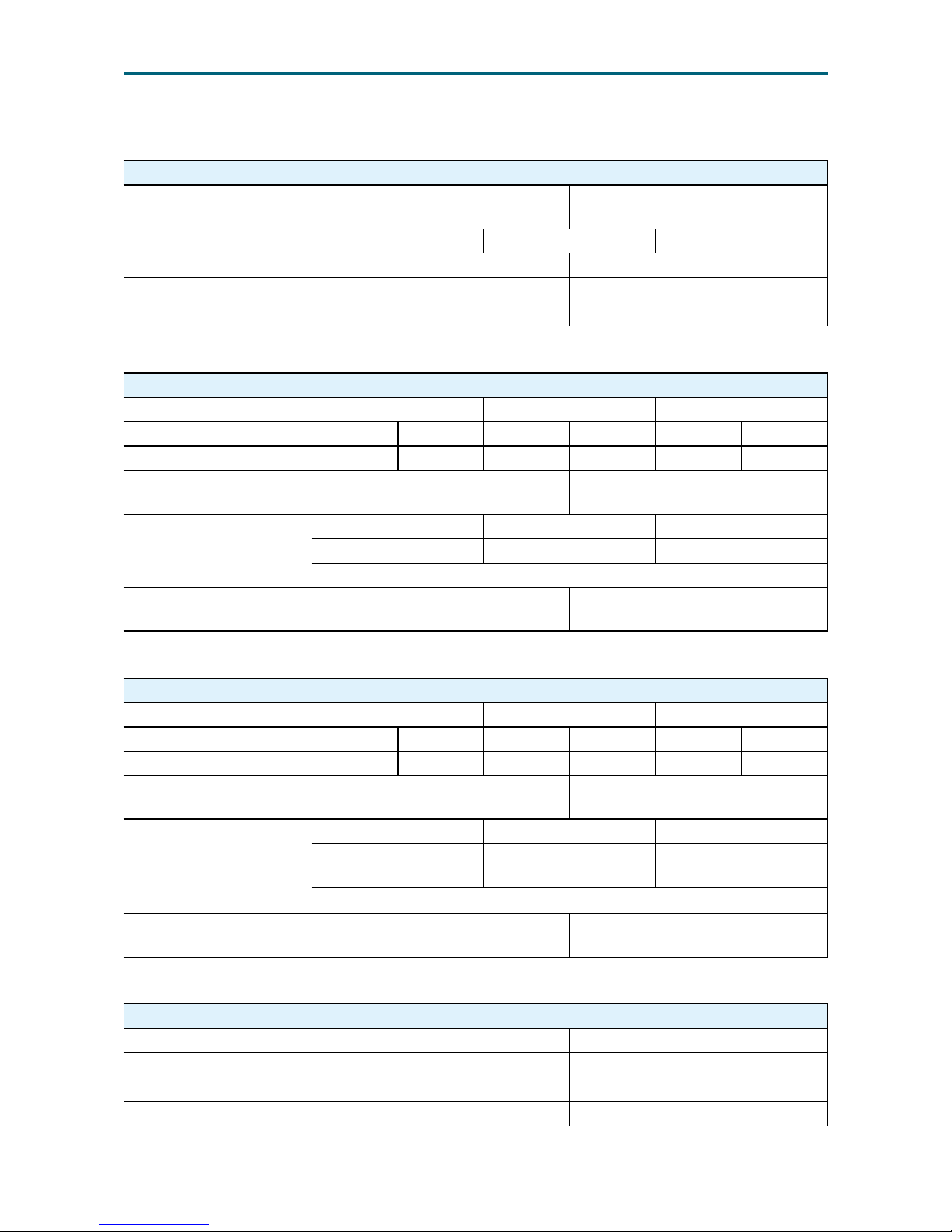
4.4.7 CSM Conguration
CSM Conguration
CSM Support
Enable
Disable
Boot option lter UEFI and Legacy Legacy Only UEFI Only
Network UEFI Legacy
Storage UEFI Legacy
Video UEFI Legacy
4.4.8 IIO0 Conguration
IIO0 Conguration
IOU2 (IIO PCIe Port 1) x4x4 x8 Auto
IOU0 (IIO PCIe Port 2) x4x4x4x4 x4x4x8 x8x4x4 x8x8 x16 Auto
IOU1 (IIO PCIe Port 3) x4x4x4x4 x4x4x8 x8x4x4 x8x8 x16 Auto
PCI-E completion
Timeout
Enable Disable
PCI-E completion
Timeout Value
50µs to 10ms 16ms to 55ms 65ms to 210ms
260ms to 900ms 1s to 3.5s 4s to 13s
17s to 64s
No PCIe port active EC0 PCU Squelch exit ignore option
Reset the SQ FLOP by
CSR option
4�4�9 IIO1 Conguration
IIO1 Conguration
IOU2 (IIO PCIe Port 1) x4x4 x8 Auto
IOU0 (IIO PCIe Port 2) x4x4x4x4 x4x4x8 x8x4x4 x8x8 x16 Auto
IOU1 (IIO PCIe Port 3) x4x4x4x4 x4x4x8 x8x4x4 x8x8 x16 Auto
PCI-E completion
Timeout
Enable Disable
PCI-E completion
Timeout Value
50µs to 10ms 16ms to 55ms 65ms to 210ms
No PCIe port active
EC0
1s to 3.5s 4s to 13s
17s to 64s
No PCIe port active EC0 PCU Squelch exit ignore option
Reset the SQ FLOP by
CSR option
4�4�10 IOAT Conguration
IOAT Conguration
Enable IOAT Enable Disable
No Snoop Enable Disable
Disable TPH Enable Disable
Relaxed Ordering Enable Disable
Page 39
30
Chapter 4. BIOS Conguration SettingsUrsa User Manual
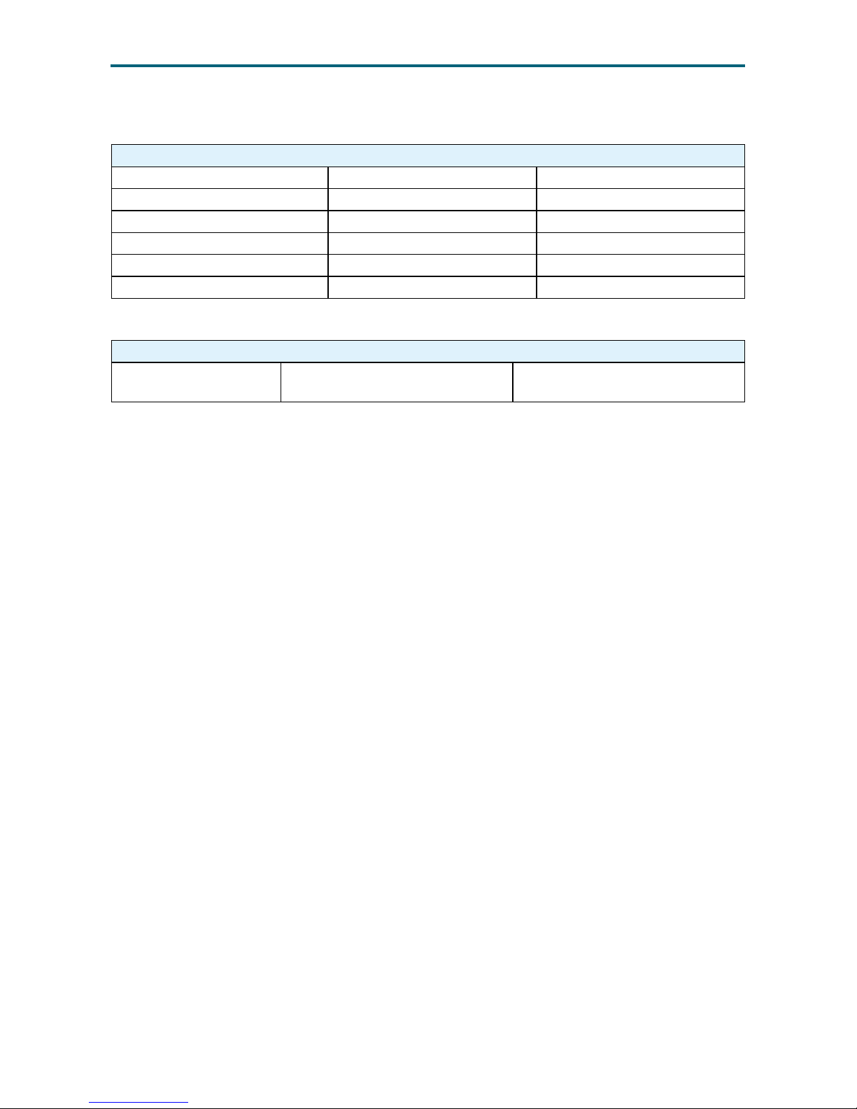
4�4�11 Intel VT for Directed I/O
Intel VT for Directed I/O (VT-d)
Intel VT for Directed I/O (VT-d) Enable Disable
Interrupt Remapping Enable Disable
Pass Through DMA Enable Disable
ATS Enable Disable
Coherency Support (Non-Isoch) Enable Disable
Coherency Support (Isoch) Enable Disable
4.4.12 USB Conguration
USB Conguration
USB Mass Storage Driver
Support
Enable Disable
Page 40
31
Chapter 4. BIOS Conguration SettingsUrsa User Manual
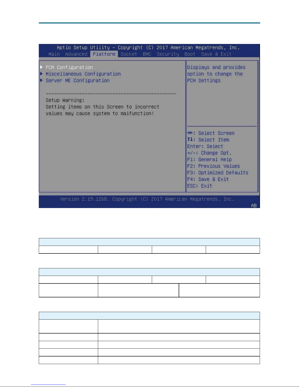
Platform Option Key:
4.5.1 PCH Conguration
PCH Conguration
Restore AC Power Loss Power Off Power On Last State
4.5.2 MIscellaneous Conguration
Miscellaneous Conguration
Active Video Auto On board device PCIE Device
RTC Wake system from
S4/S5
Enable Disable
4.5.3 Server ME Conguration
Server ME Conguration
General ME
Conguration
Congures Server ME Technology Parameters.
Oper. Firmware Version Version of operational rmware selected to run.
Current State ME rmware Current State, bits [3:0] in MEFS1.
Error Code ME rmware Error Code, bits [15:12] in MEFS1.
Recovery Cause Server ME rmware recovery cause, bits [10:8] in MEFS2.
4.5 Platform
Page 41
32
Chapter 4. BIOS Conguration SettingsUrsa User Manual
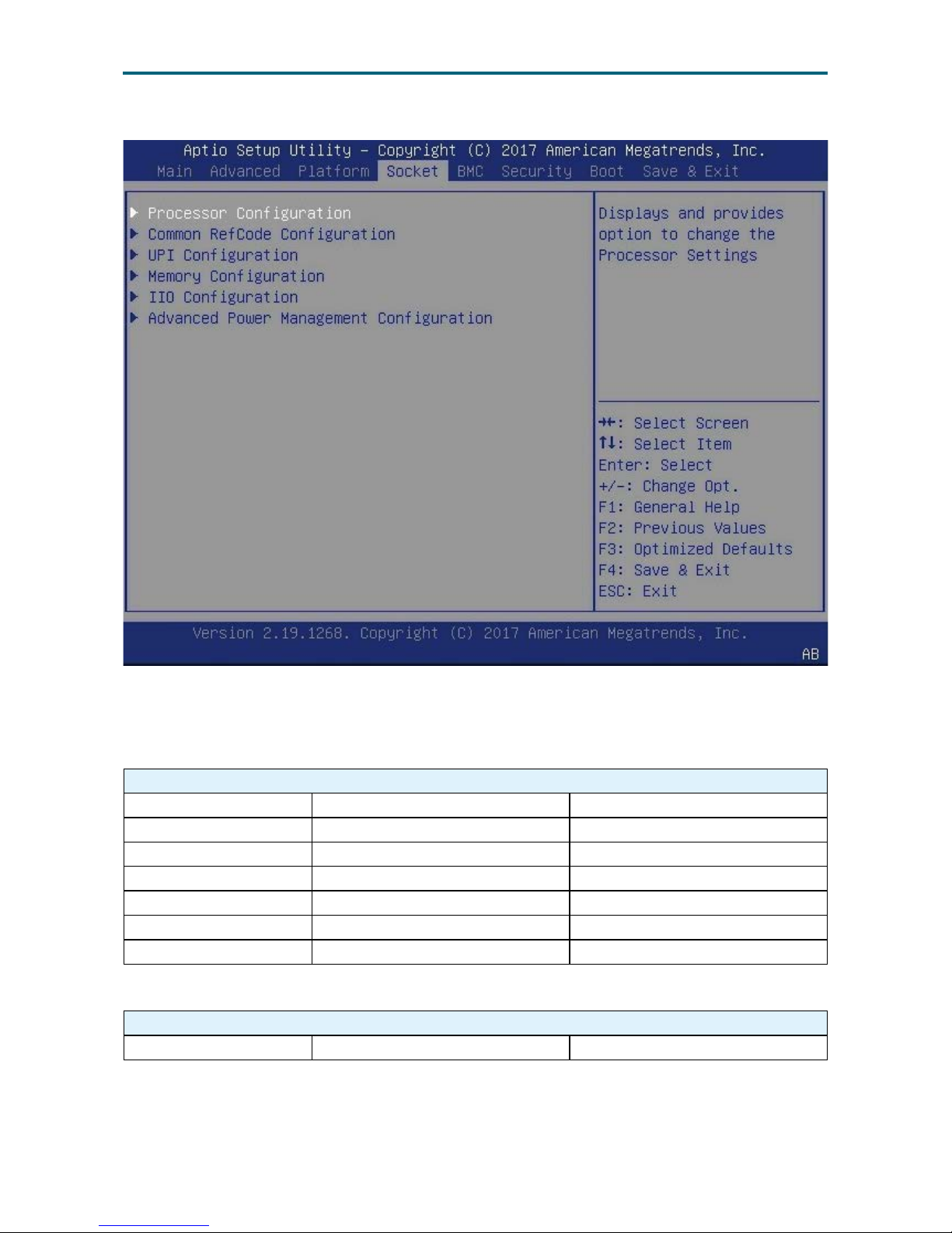
Socket Conguration Option Key:
4.6.1 Processor Conguration
Processor Conguration
Hyper-Threading Enable Disable
Enable Intel(R) TXT Enable Disable
VMX Enable Disable
Enable SMX Enable Disable
Extended APIC Enable Disable
Force x2APIC IDs Enable Disable
AES-NI Enable Disable
4.6.2 Common RefCode Conguration
Common RefCode Conguration
NUMA Enable Disable
4.6 Socket Conguration
Page 42
33
Chapter 4. BIOS Conguration SettingsUrsa User Manual
4.6.3 UPI Conguration
UPI Conguration
UPI Status
Read only.
UPI General
Conguration
Link Speed Mode Slow Fast
Link Frequency Select
9.6GB/s 10.4GB/s
Auto Use Per Link Setting
Link L0p Enable Enable Disable Auto
Link L1 Enable Enable Disable Auto
4.6.4 Common RefCode Conguration
Common RefCode Conguration
MMCFG 1G 1.5G 1.75G 2G 2.25G 3G
MMCFG Size 64M 128M 256M 512M 1G 2G
MMIO High Base 56T 40T 24T 16T 4T 3T 2T 1T
MMIO High Granularity
Size
1G 4G 16G 64G 256G 1024G
Numa Enable Disable
4.6.5 Memory Conguratiuon
Memory Conguration
Memory Frequency Auto 1866 2133 2400 2666
Enable ADR Enable Disable
Erase-Arm NVDIMMs Enable Disable
4�6�6 Memory Map
Memory Map
Channel Interleaving Auto 1-way Interleave 2-way Interleave 3-way Interleave
4.6.7 Memory RAS Conguration
Memory Conguration
Static Virtual Lockstep
Mode
Enable Disable
Mirror Mode Disable Mirror Mode 1LM Mirror Mode 2LM
Memory Rank Sparing Enable Disable
Correctable Error
Threshold
0x7FFF 0
SDDC Plus One Enable Disable
SDDC Enable Disable
ADDDC Sparing Enable Disable
Patrol Scrub Enable Disable
Patrol Scrub Interval 0-24
Page 43
34
Chapter 4. BIOS Conguration SettingsUrsa User Manual
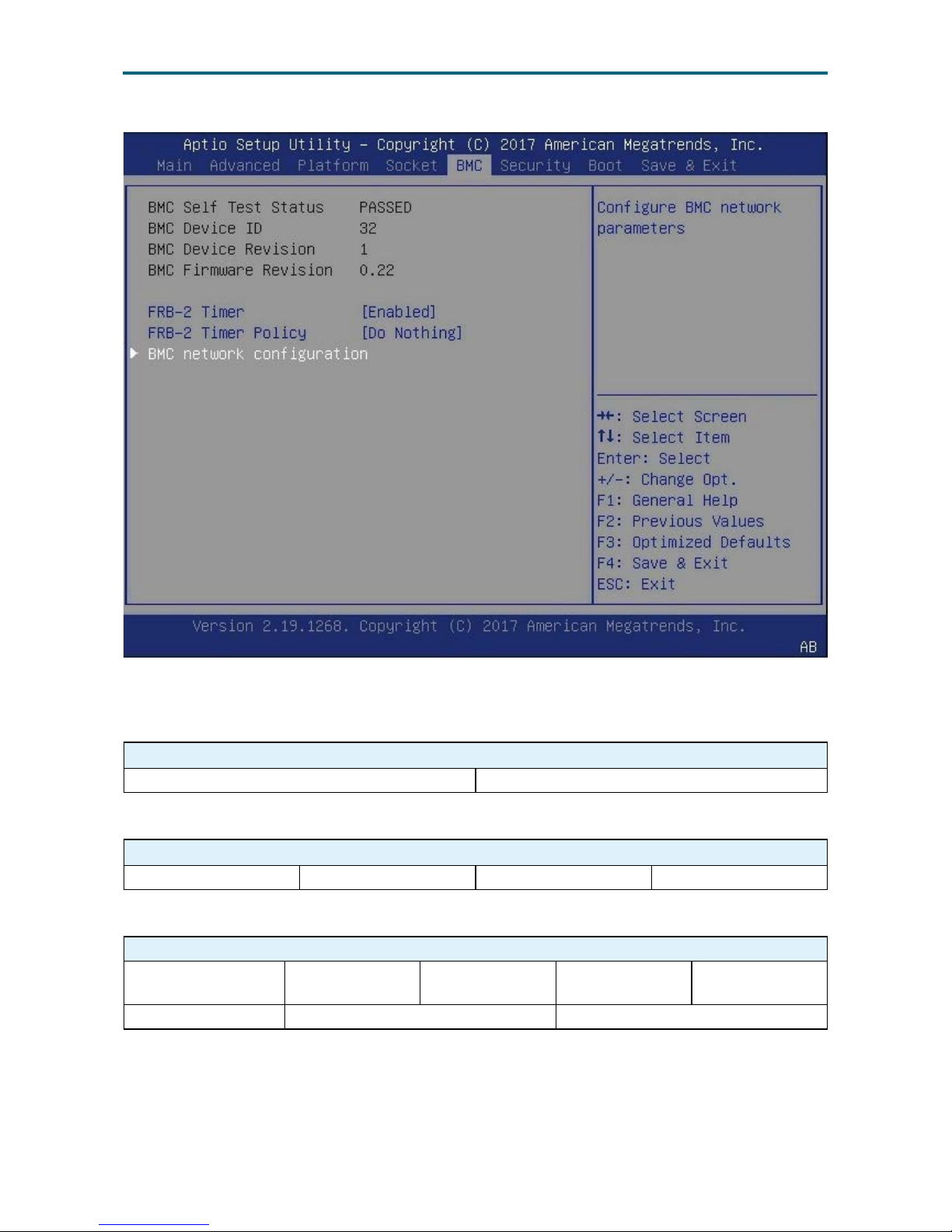
BMC Option Key:
4�7�1 FB-2 Timer
FB-2 Timer
Enable Disable
4�7�2 FB-2 Timer Policy
FB-2 Timer
Do Nothing Reset Power Down Power Cycle
4.7.3 BMC Network Conguration
BMC Network Conguration
Conguration
Address source
Unspecied Static Dynamic
-BmcDhcp
Dynamic
-BMCNonDhcp
IPV6 Support Enable Disable
4�7 BMC
Page 44
35
Chapter 4. BIOS Conguration SettingsUrsa User Manual
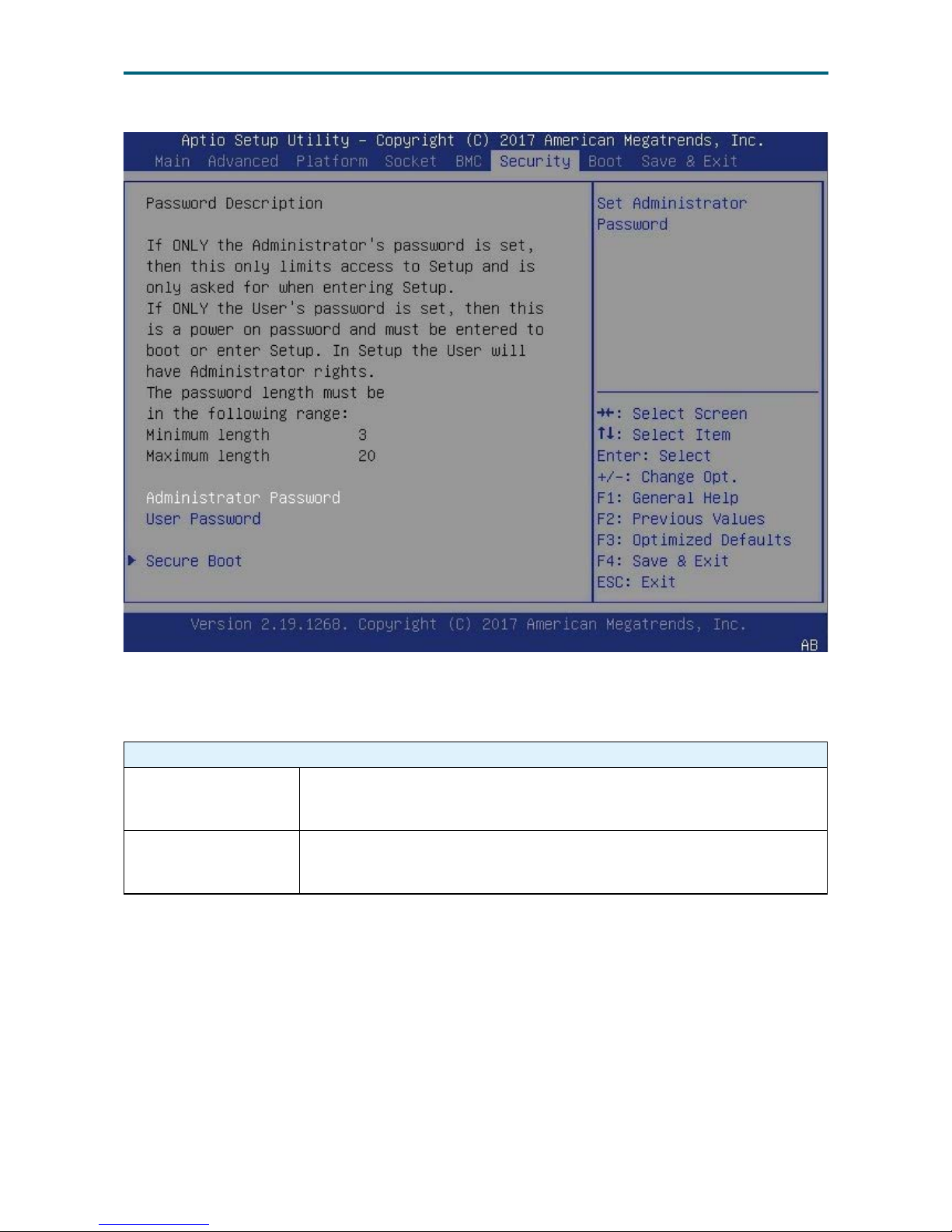
Security Option Key:
4�8�1 Security
Security
Administrator
Password
Set administrator password in the Create New Password window. After
you key in the password, the Conrm New Password window will pop
out to ask for conrmation.
User Password
Set user password in the Create New Password window. After you key in
the password, the Conrm New Password window will pop out to ask for
conrmation.
4�8 Security
Page 45
36
Chapter 4. BIOS Conguration SettingsUrsa User Manual
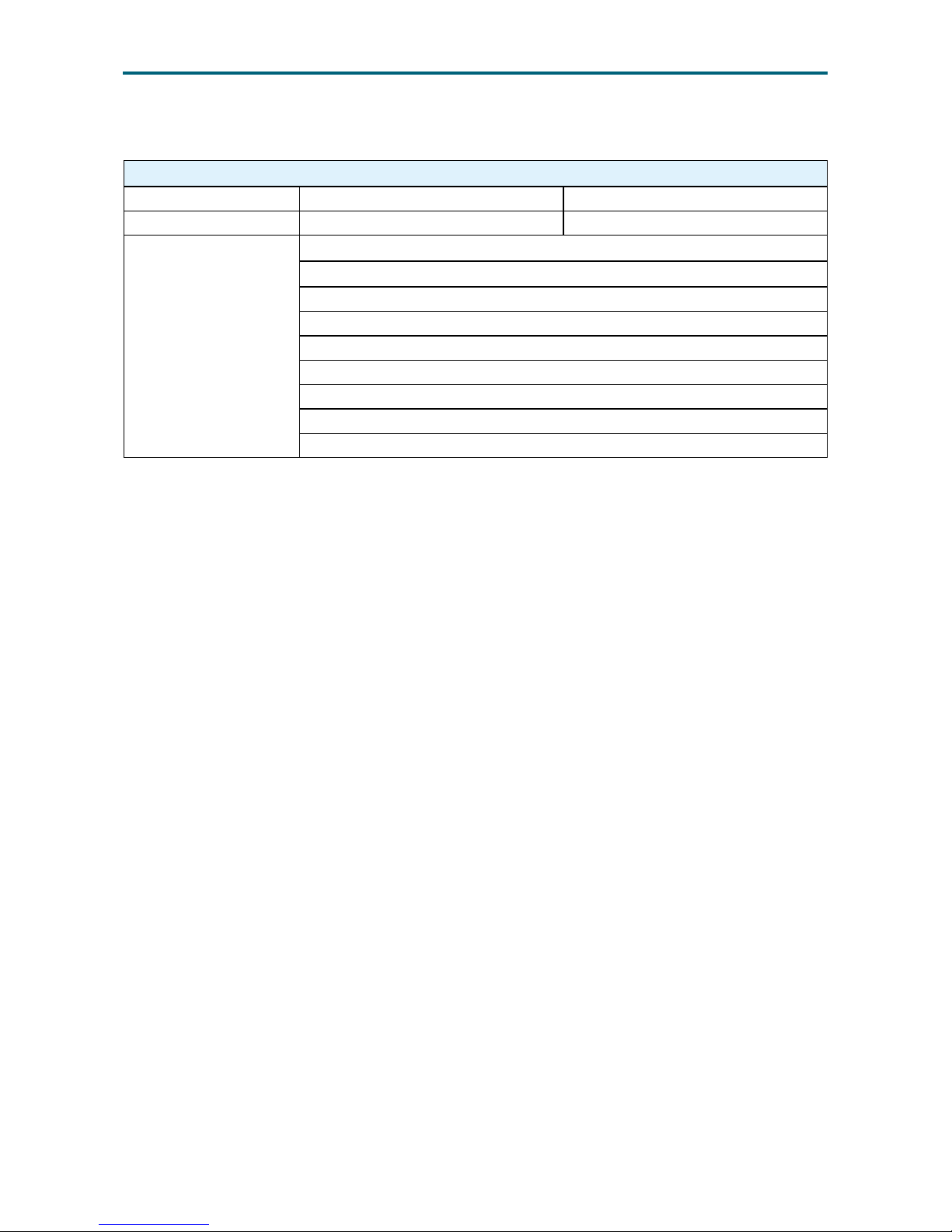
4�8�2 Secure Boot
Secure Boot
Attempt Secure Boot Enable Disable
Secure Boot Mode Standard Custom
Key Management
Provision Factory Default keys
Install Factory Default Keys
Enroll E Image
Save All Secure Boot Variables
Platform Key (PK)
Key Exchange Keys
Authorized Signatures
Forbidden Signatures
Authorized TimeStamps
Page 46
37
Chapter 4. BIOS Conguration SettingsUrsa User Manual
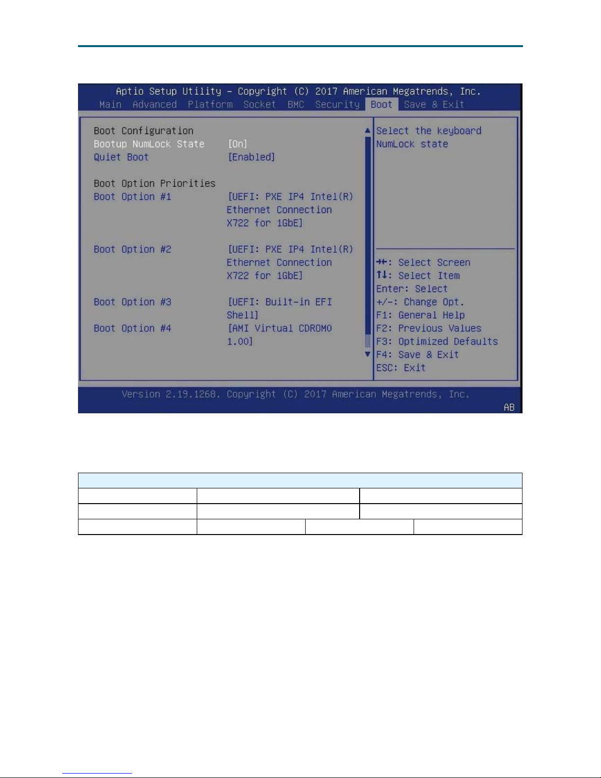
Boot Option Key:
4�9�1 Boot
Boot
Bootup NumLock State On Off
Quiet Boot Enable Disable
New Boot Option Policy Default Place First Place Last
4�9 Boot
Page 47
38
Chapter 4. BIOS Conguration SettingsUrsa User Manual
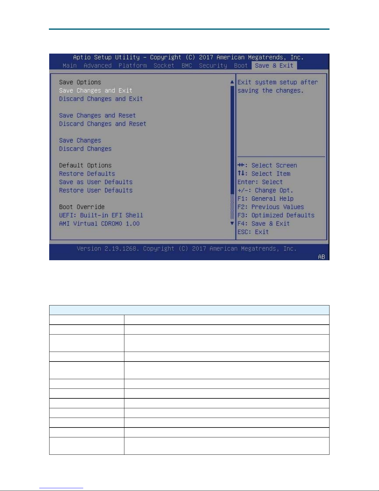
Save and Exit Option Key:
4�10�1 Save and Exit
Save and Exit
Save Options Saves changes done so far to any of the setup options.
Save Changes and Exit Exits the system setup after saving the changes.
Discard Changes and
Exit
Exits the system setup without saving any changes.
Save Changes and Reset Resets the system after saving the changes.
Discard Changes and
Reset
Resets system setup without saving any changes.
Save Changes Saves the changes.
Discard Changes Discards the changes.
Restore Defaults Restores or loads default values for all the setup options.
Save as User Defaults Saves the changes done so far as User Defaults.
Restore User Defaults Restores the User Defaults to all the setup options.
Boot Override Forces Boot device this time.
UEFI: Built-in EFI Shell
Attempts to Launch EFI Shell application (Shell.efi) from one of the
available lesystem devices.
4�10 Save and Exit
Page 48

39
Chapter 4. BIOS Conguration SettingsUrsa User Manual
4�11 Update Requirement
4�11�1 Utility
Flash BIOS image under EFI Shell: AFUEFIX64.EFI
Flash BIOS image under Linux: AFULNX_64
Flash BIOS image under Windows: AFUWINGUI.EXE
4�11�2 Update under EFI Shell
AMI Flash Utility:
1. Copy AfuEx64.e and RomFileName.BIN to USB key.
2. Boot to USB key.
3. Enter AfuEx64 <RomFileName.BIN> /P.
4. Restart the system after nishing BIOS part flashing.
If you also want to reflash ME part, follow the steps below.
5. Boot to USB key.
6. Enter AfuEx64 <RomFileName.BIN> /ME.
7. Do AC cycle system after nishing ME part flashing.
4�11�3 Update under Linux
AMI Flash Utility:
1. Copy AfuLnx_64 and RomFileName.BIN to Linux OS.
2. Open the folder with terminal.
3. Enter AfuLnx_64 <RomFileName.BIN> /P /B.
4. Restart the system after nishing BIOS part flashing.
If you also want to reflash ME part, follow the steps below.
5. Boot in Linux OS.
6. Enter AfuLnx_64 <RomFileName.BIN> /ME
7. Restart system after nishing ME part flashing.
4�11�4 Update under Windows
AMI Flash Utility:
1. Download AFUWINGUI.EXE, RomFileName.BIN to Windows.
2. Run AFUWINGUI.EXE.
3. Click “Open” to load RomFileName.BIN, check Main BIOS, NVRAM, Bootblock, and
then click “Flash.”
4. Restart the system after nishing BIOS part flashing.
If you also want to reflash ME part, follow the steps below.
5. Boot in Windows OS.
6. Run AFUWINGUI.EXE, click “Open” to load RomFileName.BIN, ME, and then click “Flash”.
7. Restart system after nishing ME part ashing.
Page 49
40
Chapter 5. BMC Conguration SettingsUrsa User Manual
This chapter displays the conguration settings of IPMI BMC in your system device.
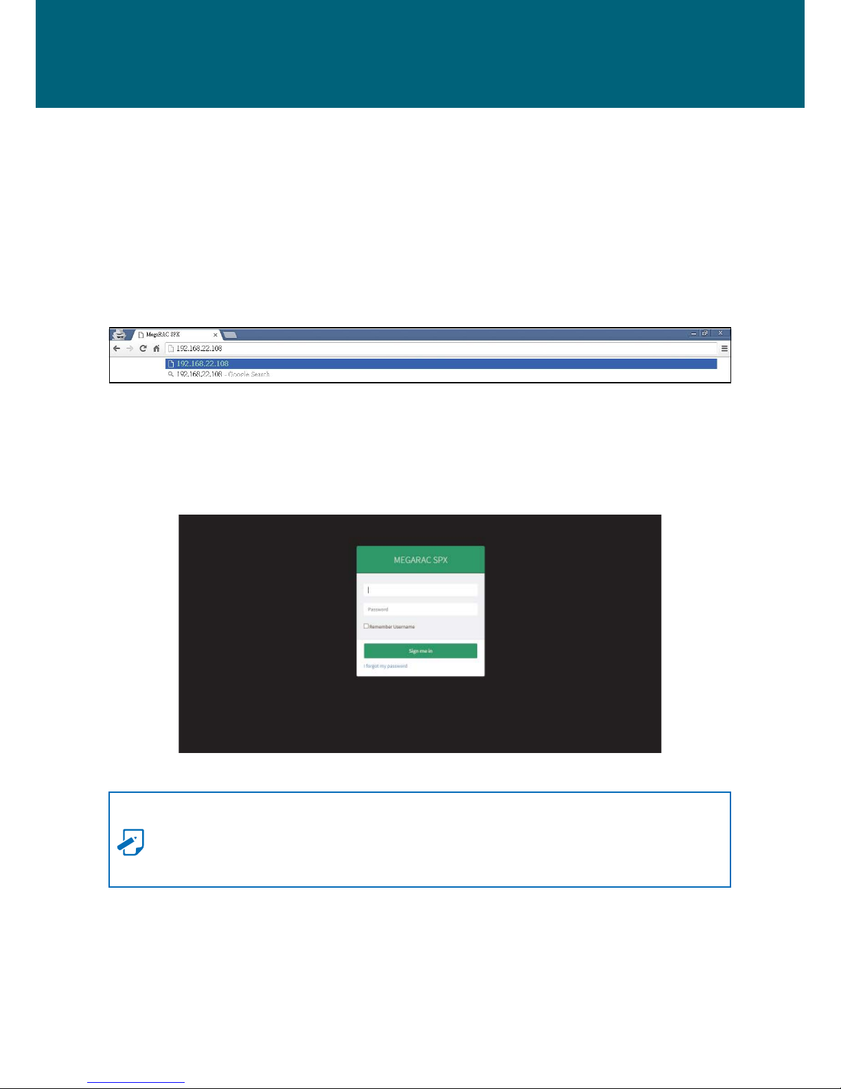
5�1 Login
The IP address below is an example using the default IP setting. The IP address is
congurable.
Step 1 Open the browser then type in the default BMC IP address: 192.168.22.108
Step 2 Use the default user name and password for rst-time BMC WEB GUI login.
Field: Default
UserName: admin
Password: admin
NOTE
The default user name and password are in lower-case characters. Users who login
with the root user name and password will have full adminstrative power. The root
password can be changed after login.
Chapter 5. BMC Conguration Settings
Page 50
41
Chapter 5. BMC Conguration SettingsUrsa User Manual
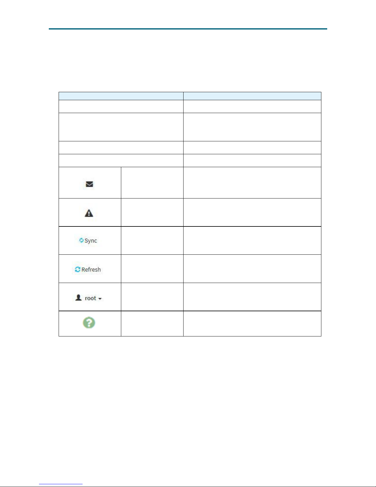
5�2�1 User Information and Quick Button
The user information and quick access buttons are located at the top right corner. It
displays the logged-in user, his/her privilege and the four quick buttons allowing you
to perform different functions.
Button Description
User Only valid commands are allowed.
Operator All BMC commands are allowed except for the
conguration commands that can change the
behavior of the out-of-hand interfaces.
Administrator All BMC commands are allowed.
No access Login access denied.
Notication Click to view notication messages.
Warning Click to view warning messages.
Sync
Click to synchronize with the latest sensor
and event log updates.
Refresh Click to reload the current page.
Root-administrator
Sign out: Click to log out of the GUI
Prole: Click to enter the User Management
Conguration dialog box in gure xx.
Help
Click to view more details on eld
descriptions.
5�2 Web GUI
Page 51
42
Chapter 5. BMC Conguration SettingsUrsa User Manual
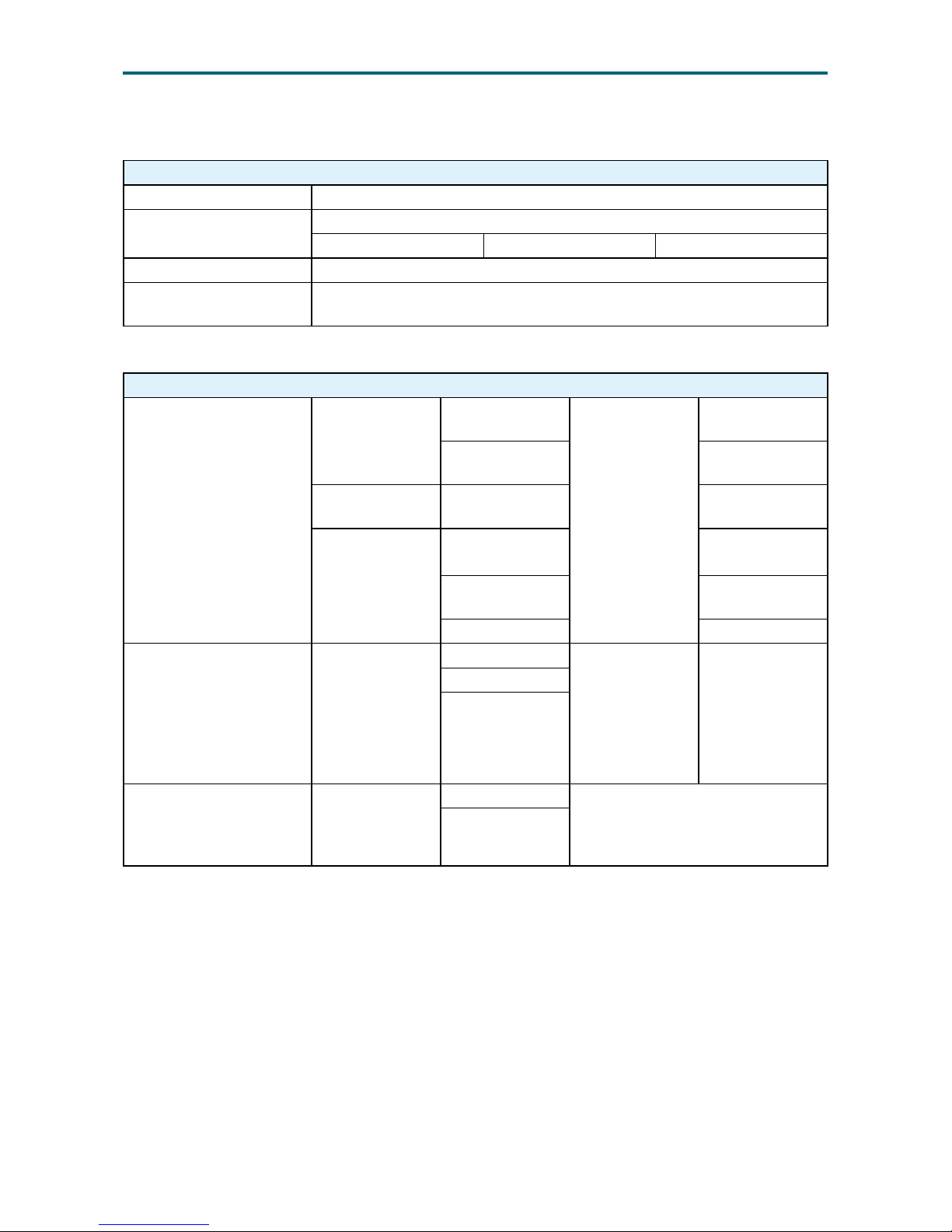
5�2�2 BMC Watchdog
BMC Watchdog
IPMI Standard Watchdog Allow host software check pointing and system recovery on a timeout.
Automatic System
Recovery
Simplify recovery of a computer's system or boot volumes.
Hard Reset Power Down Power Cycle
Watchdog Event Logging Indicate an watchdog timer timeout occured.
FRB2 Timeout Detection
Implemented with IPMI Watchdog Timer and supports BMC Watchdog
Timer Commands.
5�2�3 System LED Indicator
System LED
System
Health
(Front Panel)
Green
On
Control By CPLD
System is Good.
No Error.
Off
Normally in
Standby.
Amber Blink (1Hz)
Non-Critical
event occurred.
Red
Blink (1Hz)
Critical event
occurred.
On
Non-recovery
event occurred.
Off Normally.
UID Blue
On
UID LED only is
controlled by
CPLD when BMC
is not ready or
boot fail.
UID is able to
be controlled
by BMC and
UID button.
Blink is only be
controlled by
BMC command.
Off
Blink
Heart
Beat
(Motherboard)
Green
On Heart Beat LED is On when AC On.
After BMC ready, BMC will control
Heart Beat LED blink when BMC is
alive.
Blink (1Hz)
Page 52
43
Chapter 5. BMC Conguration SettingsUrsa User Manual
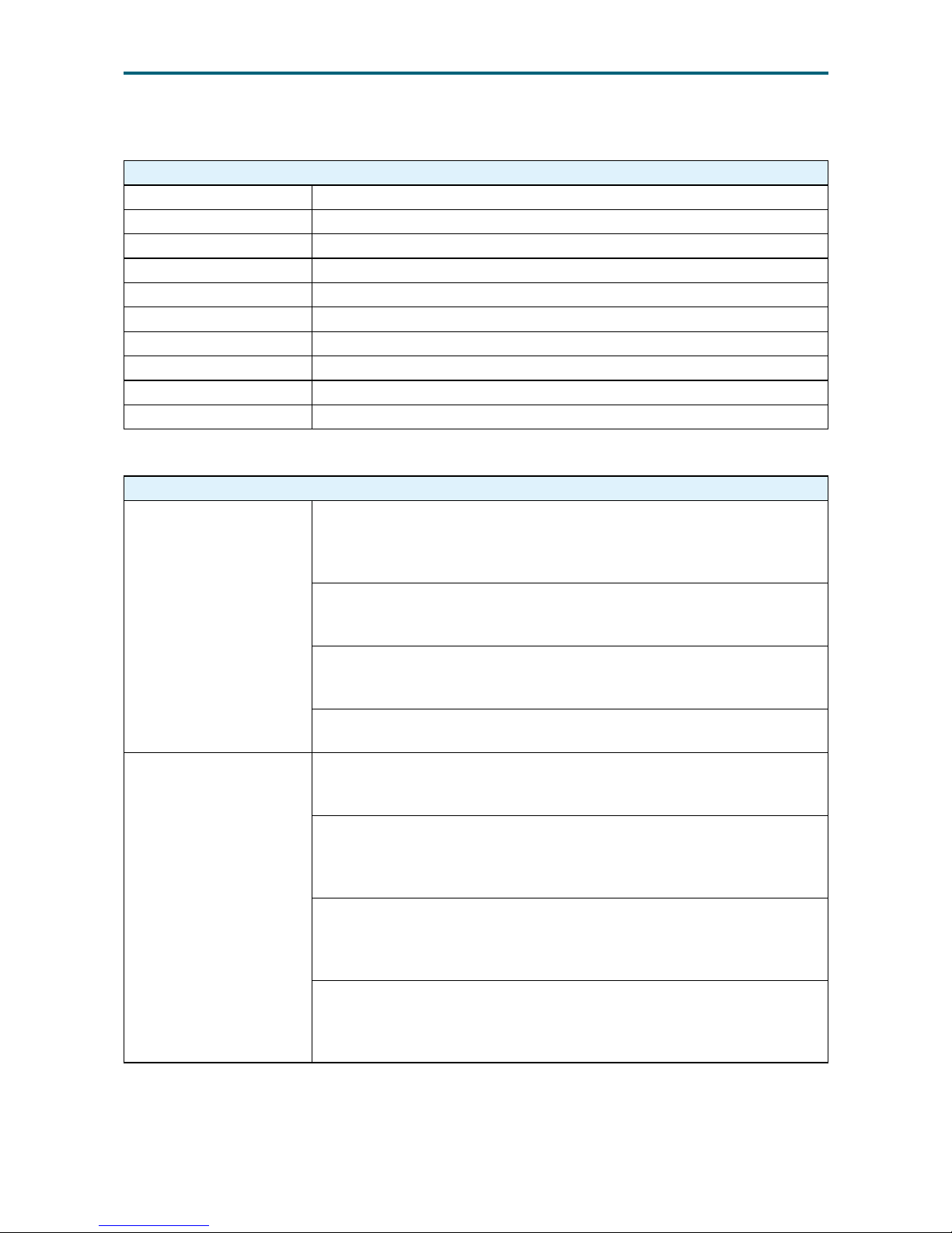
5�2�4 LAN
LAN
DHCP IP Support
LAN protocol RMCP(V1.5)+RMCP+(V2.0) support
ARP This function is implemented by BMC. (Default: Enable)
Enabled Authentications Administrator[Password]
Session timeout 1800s(default) + 10s(tolerance)
Multi session Support Max 15 sessions simultaneously
Anonymous Login Not Support
LAN Alerting Support SNMP Trap
User account Support 10 user account including USER ID 1-10
Cipher Suite Entry Support 3 entry, Cipher Suite IDs: 1, 2, 3
5�2�5 System Event Log (SEL)
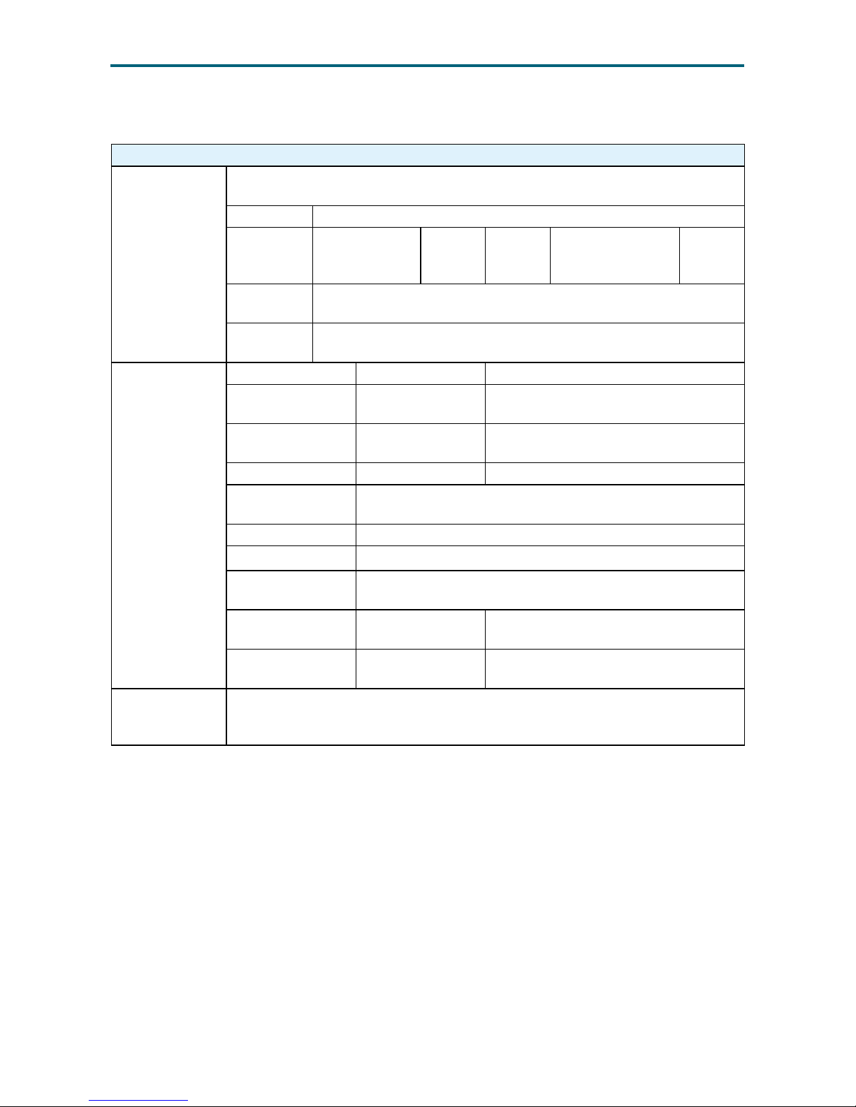
System Event Log (SEL)
Time Synchronization
Time stamping is a key part of event logging and tracking. SEL
timestamp need to be set through BIOS or System Management
Software. There are 3 scenarios that BMC would synchronize its Real
Time clock (RTC) with the host system:
• During system Power-on Self Test (POST), BIOS would wait BMC
function ready (approximate 120 sec.), then send the Set SEL Time
command with the current system time to sync RTC timer.
• In runtime, on every BMC reset, BMC will assert GPIO to generate
SMI to BIOS, then BIOS would send the Set SEL Time command
with the current system time to sync RTC timer.
• The BMC would automatically sync its RTC timer every 24 hours to
maintain the tolerance within 3sec, via issue a SMI to BIOS.
The Behavior when SEL
is full.
Single Entry Delete:
The Delete SEL Entry Command of IPMI is able to remove the
individual records.
SEL Entry for SEL overflow:
When SEL is about to ll, the last entry recorded would be a SEL
entry stating the SEL has overflowed. This entry gives the system an
indication that subsequent SEL entries were lost.
SEL Circle Log:
When SEL is full, the system will record an "overflow" message and the
oldest log is instead of a new one. And then it records an event for “SEL
full”.
SEL Clear:
When all events are captured by SMS tool, SMS tool is able to clear
SEL entry. After all events are cleaned, SEL agent will create a new
event for this action.
Page 53
44
Chapter 5. BMC Conguration SettingsUrsa User Manual
5�2�6 Serial Interface
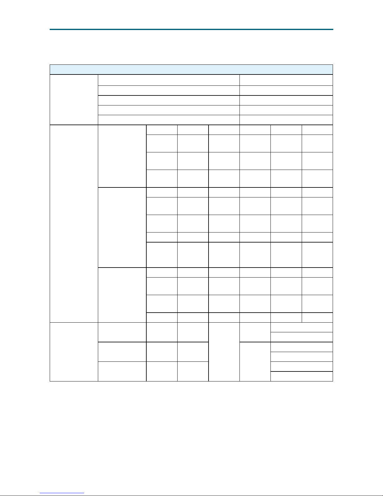
Serial Interface
Serial Over LAN
(SOL)
SOL Information
Serial over LAN enables the serial controller of a managed system to be
redirected over an IPMI session over IP.
Channel# 0x01
Baud Rate 9600 19200 38400 57600
115200
(default)
BPS
Flow
control
Hardware flow control
Payload
port
623
SOL
Conguration
OL Enable Disabled Disable SOL payload type
SSOL
Authentications
Administrator Administrator access over SOL
Non-Volatile Bit
Rate
115200 115200 baud rate.
Volatile Bit Rate 115200 115200 baud rate.
Gratuitous ARP
Interval
4 seconds
ARP responses Enabled
Access Mode Enabled
Access Privilege
Limit
Enabled
Enabled
Authentications
Administrator
[Password]
All other Authentications disabled.
SOL Payload
Access
Enabled Enable SOL payload access.
The Behavior of
SOL
The BMC is able to connect and switch UART port between COM Port 1 and
SOL. If the SOL connection is abnormal, the watchdog of BMC would reset
itself and return conguration (routing) to the default settings.
Page 54
45
Chapter 5. BMC Conguration SettingsUrsa User Manual
5�2�7 RMCP(IPMI v1�5)/RMCP + (IPMI v2�0) and Payload Support
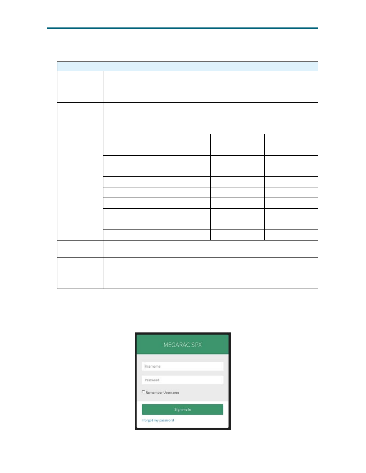
RMCP(IPMI v1�5)/RMCP+(IPMI v2�0) and Payload Support
RMCP
Payloads
OEM Disable
Straight Password Enable
MD5 Enable
MD2 Enable
None Authentication Enable
RMCP+
Payloads
Authentication
None O X O O X
HMAC
SHA1
O O O O X
HMAC
MD5
X X X X X
HMAC
SHA2
X X X X X
Integrity
None O O O O X
HMAC
SHA1 96
O O O O X
HMAC
MD5 128
O O X X X
MD5 128 X X X X X
HMAC
SHA2
128
X X X X X
Condentiality
None O O O O X
AES CBC
128
O O O O X
XRC4
128
X X X X X
XRC4 40 X X X X X
Cipher Suite of
RMCP+
1 S
01h, 00h,
00h
RAKPHMACSHA1
None
None
Administrator
2 S,A
01h, 01h,
00h
HMACSHA1-96
None
Administrator
3 S,A,E
01h, 01h,
01h
AES-CBC-128
Administrator
S = authenticated session setup (correct role, username and password/key required to
establish session)
A = authenticated payload data supported.
E = authentication and encrypted payload data supported
Page 55
46
Chapter 5. BMC Conguration SettingsUrsa User Manual
5�2�8 Remote KVM
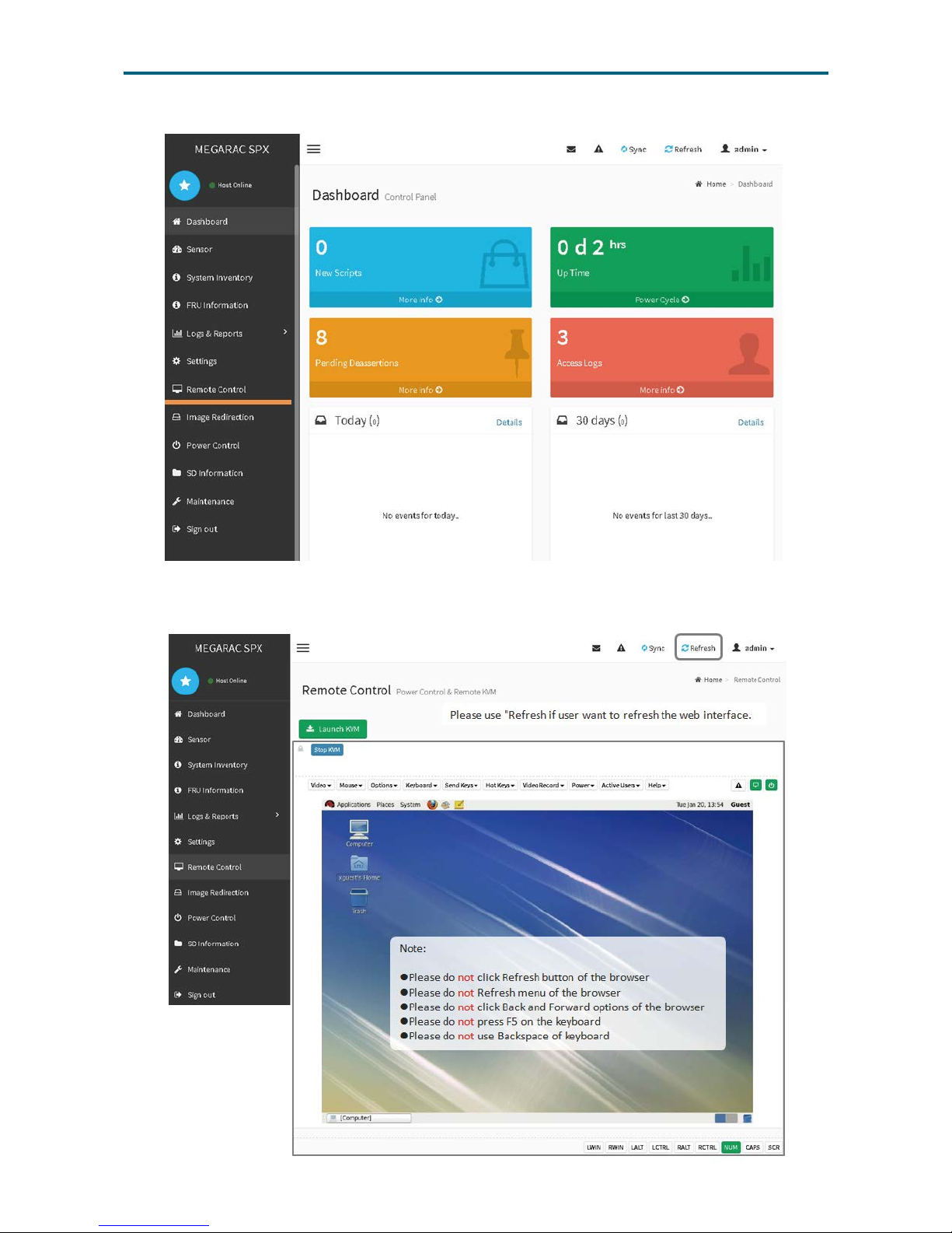
Remote KVM
KVM over IP
Because Remote KVM solutions operate out-of-band of the system
processor, they don’t place undue burdens on the host processor. This also
means that, although the Remote KVM resides in the server box, but it will
not put extra loading to the host processor.
Browser
Support
Internet Explorer (IE) 11.0 or later version for Windows platforms.
Firefox 34 or later version for all platforms
Google Chrome 47 or later version
Screen
Resolution and
Color Depth
640x480 60 Yes Yes
800x600 60 Yes Yes
1024x768 60 Yes Yes
1280x800 60 Yes Yes
1280x1024 60 Yes Yes
1440x900 60 Yes Yes
1600x1200 60 Yes Yes
1680x1050 60 Yes Yes
1920x1080 60 Yes Yes
1920x1200 60 Yes Yes
Full Screen and
Window Mode
The console is capable of viewing the server side screen in both windowed
and the full screen.
Simultaneous
Console Users
The KVM/IP console must provide up to three simultaneous users login. This feature should be congurable as 1 or 2 simultaneous console at
a time. The rst user gets the total control of the console including the
keyboard/mouse. The others can only view the screen data or the activity.
Launch KVM:
Step 1: Open a supported browser.
Step 2: Enter the web address with the IP.
Step 3: Enter the User name and password to launch the KVM function.
Page 56
47
Chapter 5. BMC Conguration SettingsUrsa User Manual
Step 4: Select "Remote Control" from the menu bar. The KVM window will pop up.
Step 5: Click the button "Start KVM." To terminate the KVM service, click "Stop KVM."
Page 57
48
Chapter 5. BMC Conguration SettingsUrsa User Manual
5�2�9 BMC Booting
BMC Booting
Firmware
Integrity Check
The BMC boot loader will verify the checksum of the loaded rmware image
before executing it. If the boot loader detects that the loaded rmware image
is invalid, it will not be executed. BMC will select another SD storage for
boot. If Both of ROMs part are fail, BMC SOC will reboot by WDT again.
Boot Time
From the point of reset, the BMC boot to fully operational state and be
responsive to the host on KCS channel within 30 seconds. And LAN channel
interface will be enable after 78 seconds.
Page 58

Chapter 6� Technical Support
Taiwain, Global Headquarters
Address: No� 152, Section 4,
Linghang N� Rd, Dayuan District,
Taoyuan City 337, Taiwan
Tel: +886-3-433-9188
Fax: +886-3-287-1818
Sales Email: sales@aicipc�com�tw
Support Email: support@aicipc�com
Shanghai, China
Address: Room 1009, No� 777,
Zhaojia Bang Rd, Shanghai 200032,
Shanghai, China
Tel: +86-21-54961421
Fax +86-21-54961422 #608
Sales Email: csales@aicipc�com�tw
Support Email: support@aicipc�com
Moscow, Russia
Address: Khoroshevskoye Shosse, 32A,
Ofce 403 (2nd Entrance, 4th Floor),
Moscow 123007, Russia
Tel: +7-4997019998
Sales Email: support-ru@aicipc�com�tw
Support Email: support-ru@aicipc�com�tw
North California, United States
Address: 48531 Warm Springs
Boulvard Suite 404 Fremont, CA
94539, United States
Tel: +1-510-573-6730
Fax: +1-510-573-6729
Sales Email: sales@aicipc�com
Support Email: support@aicipc�com
South California, United States
Address: 21808 Garcia Lane
City of Industry, CA 91789,
United States
Toll free: +7-4997019998
Tel: +1-909-895-8989
Fax: +1-909-895-8989#157
Sales Email: sales@aicipc�com
Support Email: support@aicipc�com
New Jersey, United States
Address: 11 Melanie Lane
Unit #20 & 21
East Hanover, NJ 07936, United States
Tel: +1-973-884-8886
Fax: +1-973-884-4794
Sales Email: sales@aicipc�com
Support Email: support@aicipc�com
Houten, The Netherlands
Address: Peppelkade 58, 3992AK, Houten,
The Netherlands
Tel: +31-30-6386789
Fax: +31-30-6360638
Sales Email: sales@aicipc�nl
Support Email: support@aicipc�com
 Loading...