

Page 1

Pavo
Server MotherBoard
User's Manual
UM_Pavo_v1.2_101817
Page 2

contents
CONTENTS
Safety Information �������������������������������������������������������������������������� i
About This User Manual ����������������������������������������������������������������� ii
Chapter 1� Product Introduction ������������������������������������������������ 1
1�1 General Information ���������������������������������������������������������������������������1
1.2 Specications �������������������������������������������������������������������������������������2
Chapter 2� Hardware Installation ����������������������������������������������� 3
2�1 Central Processing Unit (CPU) �����������������������������������������������������������3
2�2 System Memory & SFF-8643 ���������������������������������������������������������������7
Chapter 3� Motherboard Settings ��������������������������������������������� 11
3�1 Motherboard block diagram ����������������������������������������������������������11
3�2 Motherboard Layout ������������������������������������������������������������������������12
3�3 Motherboard Content List ����������������������������������������������������������������13
3�4 Internal Connectors/Jumpers ��������������������������������������������������������14
3�5 LEDs ���������������������������������������������������������������������������������������������������20
Chapter 4. BIOS Conguration and Settings ��������������������������� 24
4�1 Updating BIOS �����������������������������������������������������������������������������������26
Chapter 5. BMC Conguration and Settings ��������������������������� 28
5�1 Method 1 (Use the BIOS setup) �������������������������������������������������������28
5�2 Method 2 (Use a Dos tool - Syscheck) �������������������������������������������31
5�3 Connect to BMC �������������������������������������������������������������������������������33
5�4 Updating BMC Firmware ������������������������������������������������������������������37
Chapter 6� Technical Support��������������������������������������������������� 38
Page 3

Copyright © 2017 AIC, Inc� All Rights Reserved�
This document contains proprietary information about
AIC products and is not to be disclosed or used except in
accordance with applicable agreements.
Page 4

i
Safety Information
When installing, operating, or performing maintenance on this equipment, the
following safety precautions should always be observed in order to reduce the
risk of re, electric shock, and personal injury.
Read and understand all instructions.
• Observe warnings and instructions marked on the product.
• For proper mounting instructions, please consult the User’s Manual provided
with this product.
• Do NOT place this product on an unstable cart, stand, table or uneven
surface that might cause the product to fall and sustain serious damage.
• Only install the equipment identified in the User’s Manual. Use of other
equipment could cause improper connection of circuitry and may result in
re or personal injury.
• This product should only be operated with the type of power source
indicated on the marked label. If you are uncertain about which type
of power supply is used in your area, consult your dealer or local Power
Company.
• Disconnect the power supply module before removing power from the
system.
• Unplug this product from the wall outlet before cleaning. Use a damp cloth
for cleaning. Do not use liquid cleaners or aerosol cleaners.
• Do not use this product near a water source, such as a faucet.
• Never spill liquids of any kind on this product.
• Never shove objects of any kind into this product’s open slots, as they may
touch dangerous voltage points or short out parts and could result in re or
electric shock.
• Do not block or cover slots and openings in this unit, as they were made for
ventilation and prevent this unit from overheating. Do not place this product
in a built-in installation unless proper ventilation is available.
• Do not disassemble this product. This product should only be taken apart
by trained personnel. Opening or removing covers and circuit boards may
expose you to electric shock or other risks. Incorrect reassembly can also
cause electric shock when the unit is subsequently used.
• Risk of explosion is possible if battery is replaced with an incompatible type.
Dispose of used batteries accordingly.
• This product is equipped with a three-wire grounding type plug, a plug with
a third (grounding) pin. As a safety feature, this plug is intended to t only
into a grounding type power outlet. If you are unable to insert the plug into
the outlet, contact your electrician to replace the outlet. Do not remove the
grounding type plug or use a 3-Prong To 2-Prong Adapter to circumvent the
safety feature; doing so may result in electric shock and/or damage to this
product.
Page 5

ii
About This User Manual
This document provides a detailed description of the Motherboard including:
• General Features of the Product
• Hardware Setup
• Motherboard Settings
• BIOS Conguration and Settings
• BMC Conguration and Settings
Product features and specications are subject to change without notice.
CAUTION :
risk of explosion if battery is replaced by an incorrect type.
dispose of used batteries according to the instructions.
After performing any installation or servicing, make sure the
enclosure are lock and screw in position, turn on the power.
Page 6
1
Chapter 1 Product Introduction
Pavo User's Manual
1�1 General Information
Chapter 1� Product Introduction
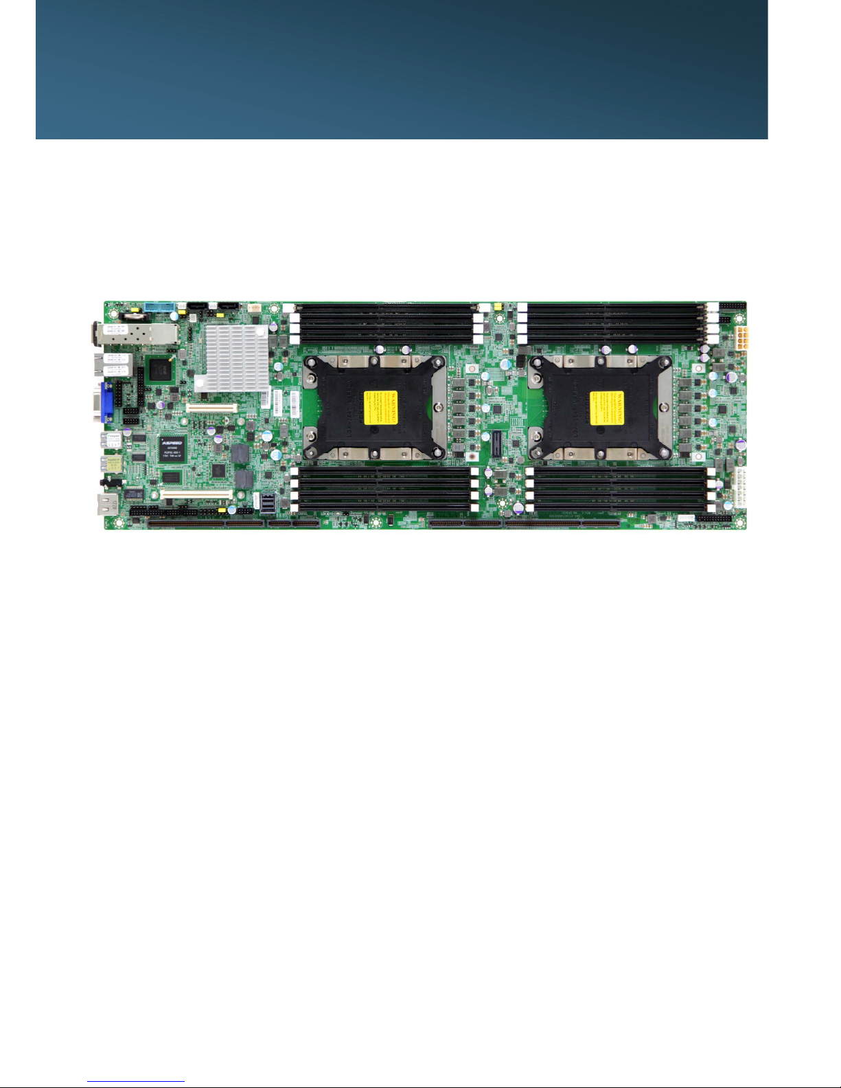
Pavo, a server grade mother board supports Xeon Processor Scalable
Family
Page 7
2
Chapter 1 Product Introduction
Pavo User's Manual
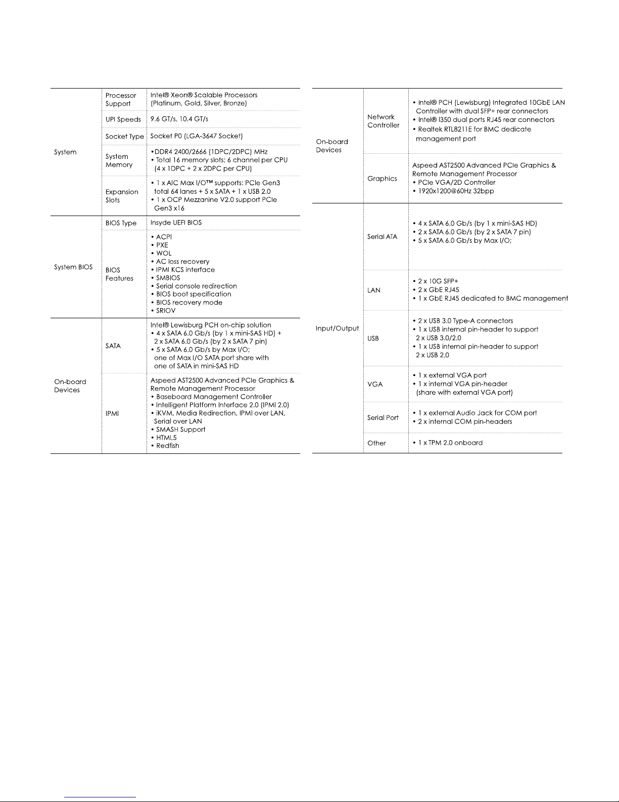
1.2 Specications
Page 8
Chapter 2 Hardware Installation
3
Pavo User's Manual
Chapter 2� Hardware Installation
2�1 Central Processing Unit (CPU)
2.1.1 Processor Support
The server board includes two processor sockets (LGA3647) and can
support one or two of the Intel® Xeon® Processor Scalable Family, with a
Thermal Design Power (TDP) of up to 165W on selected models.
WARNING :
Previous generations o f the Intel® Xeon® processors, and previ-
ous generations o f Processor heat s inks are not compatible
with the Intel® Server Board S2600BP Product Family. Processor
installation requires that the processor b e attached t o the
processor heat sink using a specific processor carrier clip, prior
to installation onto the server board.
Page 9
Chapter 2 Hardware Installation
4
Pavo User's Manual
2.1.2 Processor Heat Sink Module and Processor Socket Assembly
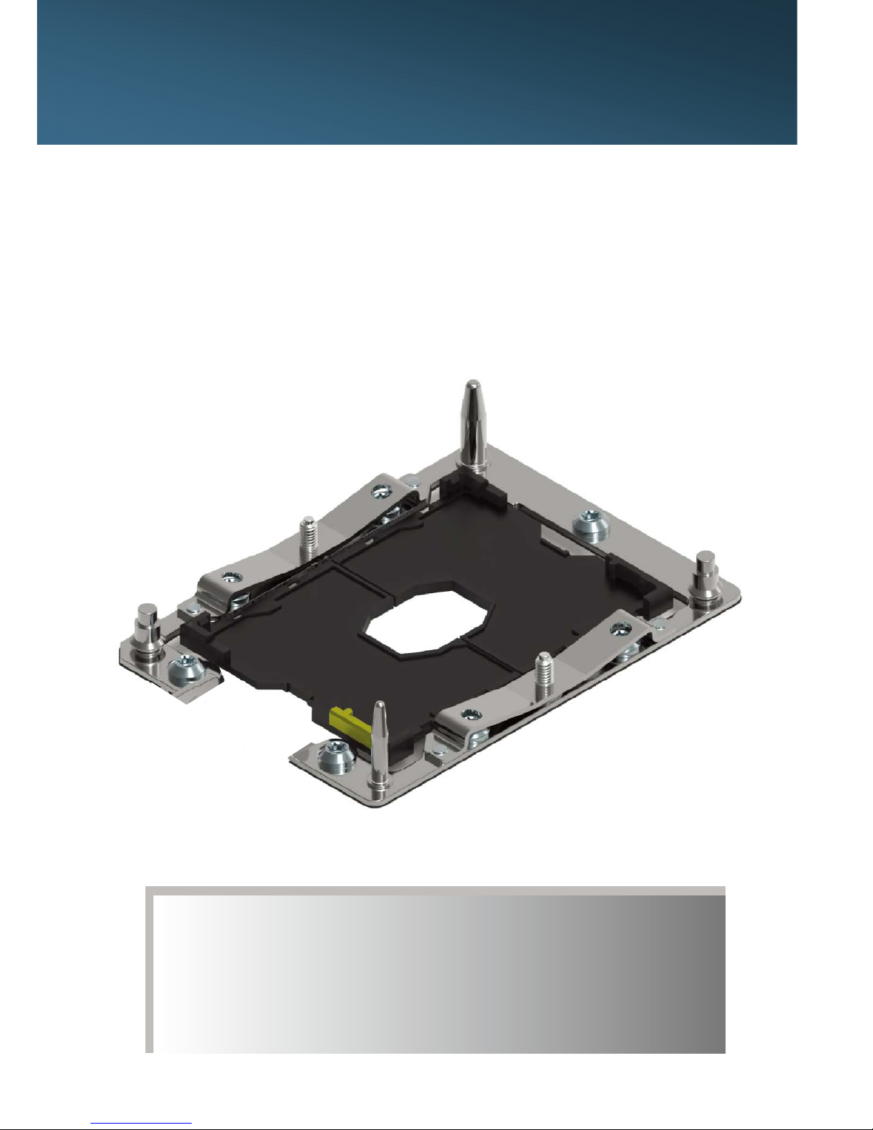
Each processor socket of the server board is pre-assembled with
a loading mechanism that allows to secure the placement of the
Processor Heat Sink Module (PHM) to the server board as shown below.
Page 10
Chapter 2 Hardware Installation
5
Pavo User's Manual
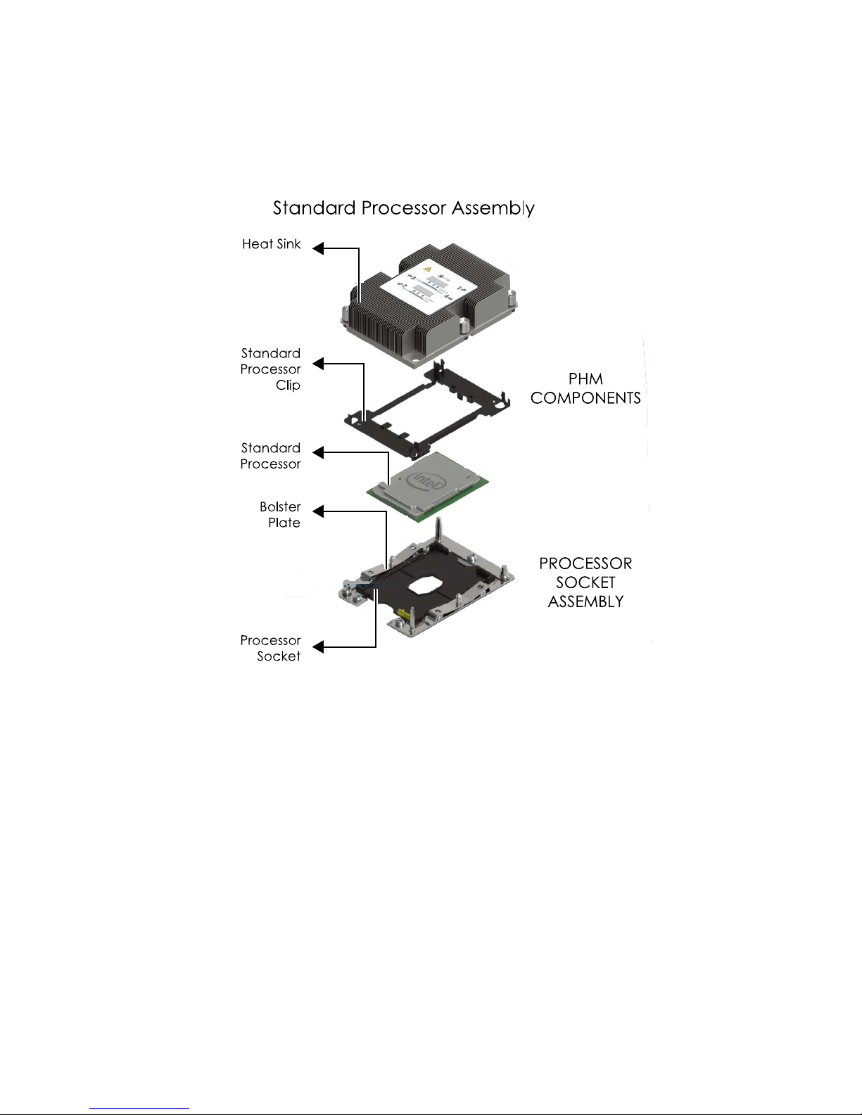
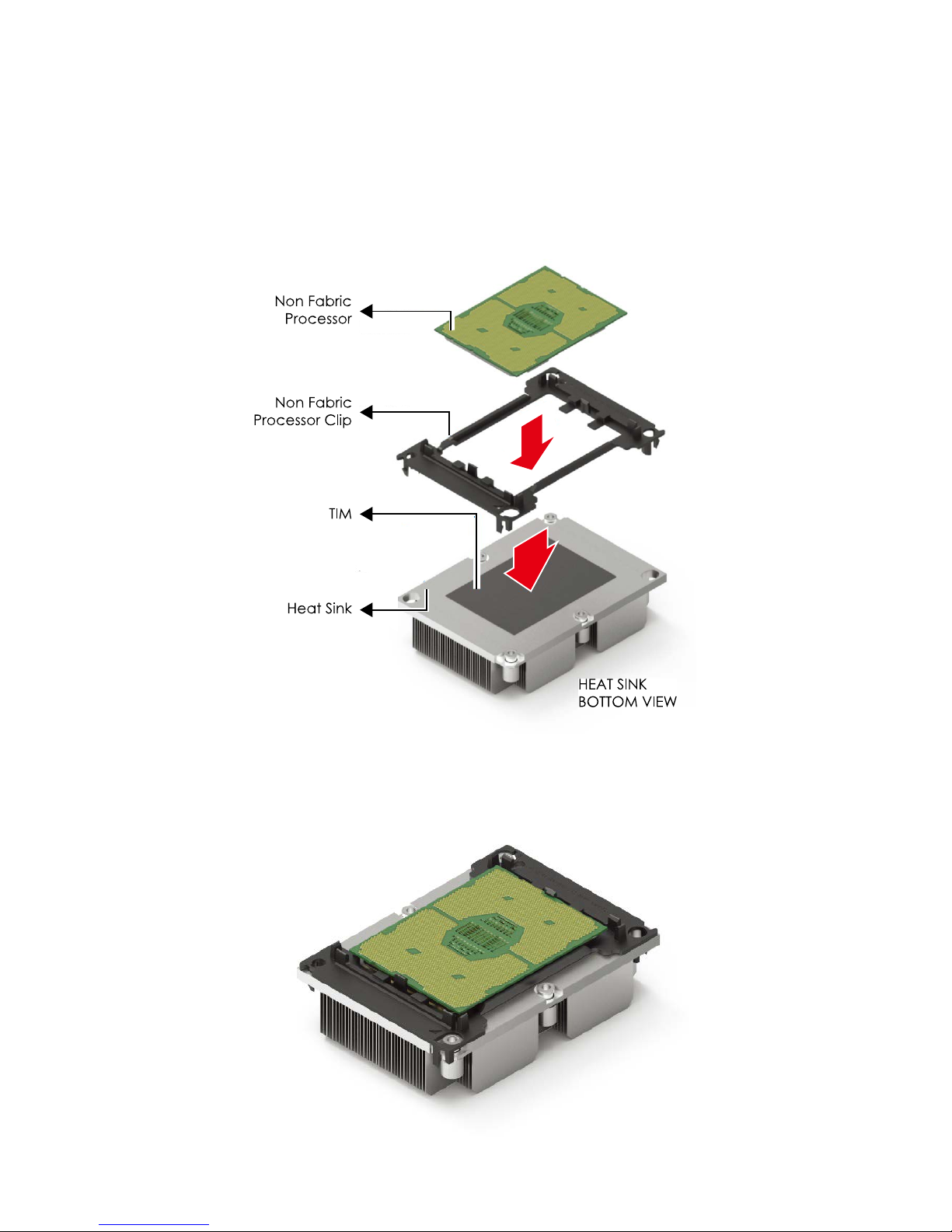
2.1.3 Processor Heat Sink Module
The PHM refers to the sub-assembly where the heat sink and processor
are clipped together prior to installation onto the server board. The PHM
consists of the components shown below.
Processor Heat Sink Module (PHM) Sub-Assembly
Processor Heatsink Module (PHM)
Page 11

Chapter 2 Hardware Installation
6
Pavo User's Manual
The PHM sits level with the processor socket assembly. The PHM is
NOT installed properly if it does not sit level with the processor socket
assembly. Once the PHM is seated over the processor socket assembly,
the four heat sink torque screws must be tightened in order as shown
below.
Processor Heat Sink – Top View with Screw Tightening Order
note :
Failure t o tighten the heat sink screws in the specified order
may cause damage t o the processor socket assembly. Heat s ink
screws should b e tightened t o 12 In-Lbs T orque o n indicated
order on the top of the heat sink label.
Page 12
Chapter 2 Hardware Installation
7
Pavo User's Manual
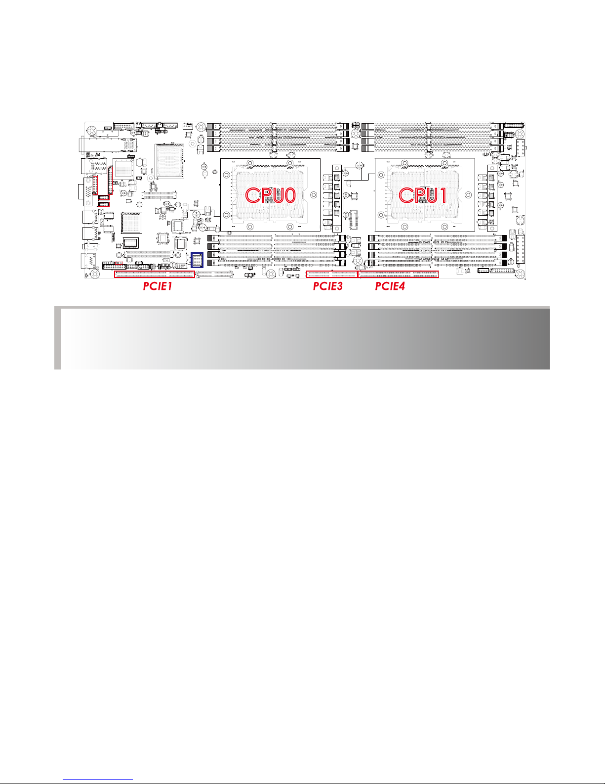
2�2 System Memory & SFF-8643
This server board supports up to sixteen DDR4 2400 and 2666 Registered
ECC DRAM / Load-Reduced DIMM (LRDIMM).
CPU0CPU0 CPU1CPU1
note :
In PAVO case, the 16 lanes from CPU#0 and the 8 lanes from CPU#1 are routed to
pcie slots 1.
The lanes from cpu#1 are routed to pcie slots 3/4.
Page 13
Chapter 2 Hardware Installation
8
Pavo User's Manual
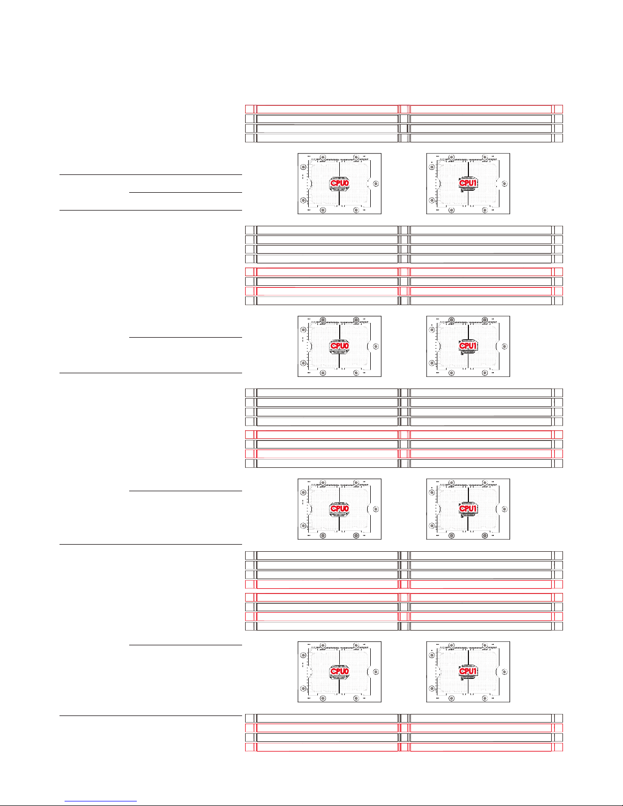
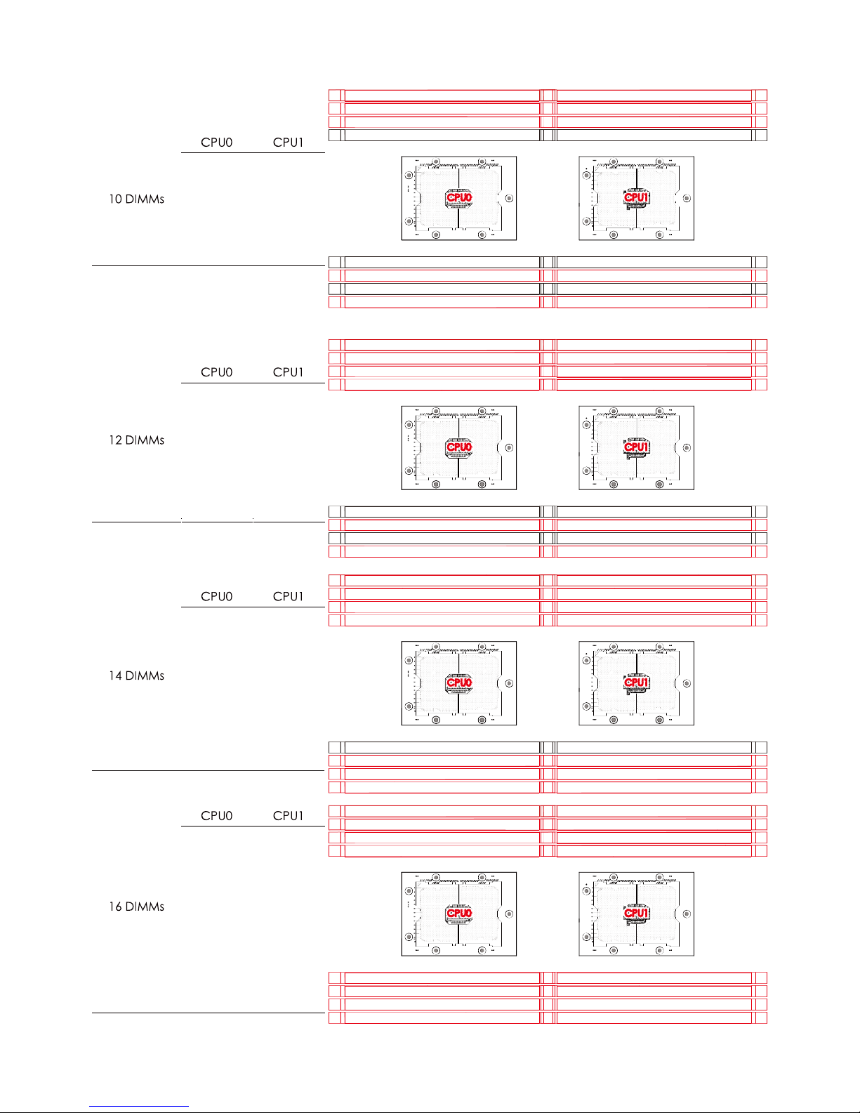
2.2.1 Populate DIMMs in the following order
:
JDIMMD2
JDIMMK2
JDIMML
JDIMMM
JDIMMK1JDIMMD1
JDIMME
JDIMMF
JDIMMC
JDIMMB
JDIMMA1
JDIMMA2
JDIMMJ
JDIMMH
JDIMMG1
JDIMMG2
DIMM Numbers DIMM ARRANGMENT
2 DIMMs
CPU0 CPU1
JDIMM_C JDIMM_J
CPU0CPU0 CPU1CPU1
4 DIMMs
CPU0 CPU1
JDIMM_C JDIMM_J
JDIMM_A1 JDIMM_G1
CPU0CPU0 CPU1CPU1
JDIMMD2
JDIMMK2
JDIMML
JDIMMM
JDIMMK1JDIMMD1
JDIMME
JDIMMF
JDIMMC
JDIMMB
JDIMMA1
JDIMMA2
JDIMMJ
JDIMMH
JDIMMG1
JDIMMG2
6 DIMMs
CPU0 CPU1
JDIMM_C JDIMM_J
JDIMM_A1 JDIMM_G1
JDIMM_F JDIMM_M
CPU0CPU0 CPU1CPU1
JDIMMD2
JDIMMK2
JDIMML
JDIMMM
JDIMMK1JDIMMD1
JDIMME
JDIMMF
JDIMMC
JDIMMB
JDIMMA1
JDIMMA2
JDIMMJ
JDIMMH
JDIMMG1
JDIMMG2
8 DIMMs
CPU0 CPU1
JDIMM_CJDIMM_J
JDIMM_A1 JDIMM_G1
JDIMM_D1 JDIMM_K1
JDIMM_FJDIMM_M
CPU0CPU0 CPU1CPU1
JDIMMD2
JDIMMK2
JDIMML
JDIMMM
JDIMMK1JDIMMD1
JDIMME
JDIMMF
JDIMMC
JDIMMB
JDIMMA1
JDIMMA2
JDIMMJ
JDIMMH
JDIMMG1
JDIMMG2
Page 14
Chapter 2 Hardware Installation
9
Pavo User's Manual
JDIMM_C
JDIMM_B
JDIMM_A1
JDIMM_D1
JDIMM_F
JDIMM_J
JDIMM_H
JDIMM_G1
JDIMM_K1
JDIMM_M
JDIMM_C
JDIMM_B
JDIMM_A1
JDIMM_A2
JDIMM_D1
JDIMM_E
JDIMM_F
JDIMM_J
JDIMM_H
JDIMM_G1
JDIMM_G2
JDIMM_K1
JDIMM_L
JDIMM_M
JDIMM_C
JDIMM_B
JDIMM_A1
JDIMM_A2
JDIMM_D2
JDIMM_D1
JDIMM_E
JDIMM_F
JDIMM_J
JDIMM_H
JDIMM_G1
JDIMM_G2
JDIMM_K2
JDIMM_K1
JDIMM_L
JDIMM_M
CPU0CPU0 CPU1CPU1
JDIMMD2
JDIMMK2
JDIMML
JDIMMM
JDIMMK1JDIMMD1
JDIMME
JDIMMF
JDIMMC
JDIMMB
JDIMMA1
JDIMMA2
JDIMMJ
JDIMMH
JDIMMG1
JDIMMG2
JDIMM_C
JDIMM_B
JDIMM_A1
JDIMM_A2
JDIMM_D1
JDIMM_F
JDIMM_J
JDIMM_H
JDIMM_G1
JDIMM_G2
JDIMM_K1
JDIMM_M
CPU0CPU0 CPU1CPU1
JDIMMD2
JDIMMK2
JDIMML
JDIMMM
JDIMMK1JDIMMD1
JDIMME
JDIMMF
JDIMMC
JDIMMB
JDIMMA1
JDIMMA2
JDIMMJ
JDIMMH
JDIMMG1
JDIMMG2
CPU0CPU0 CPU1CPU1
JDIMMD2
JDIMMK2
JDIMML
JDIMMM
JDIMMK1JDIMMD1
JDIMME
JDIMMF
JDIMMC
JDIMMB
JDIMMA1
JDIMMA2
JDIMMJ
JDIMMH
JDIMMG1
JDIMMG2
CPU0CPU0 CPU1CPU1
JDIMMD2
JDIMMK2
JDIMML
JDIMMM
JDIMMK1JDIMMD1
JDIMME
JDIMMF
JDIMMC
JDIMMB
JDIMMA1
JDIMMA2
JDIMMJ
JDIMMH
JDIMMG1
JDIMMG2
Page 15
Chapter 2 Hardware Installation
10
Pavo User's Manual
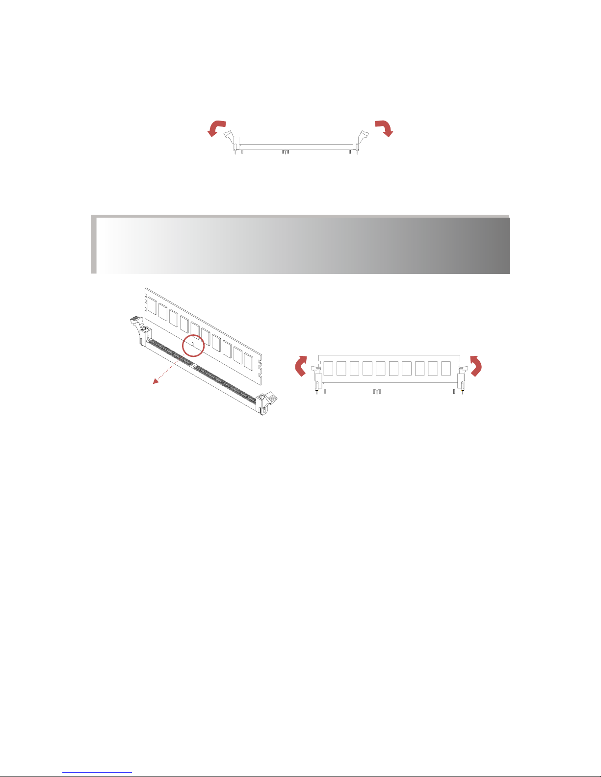
2.2.2 DIMM Installation Procedure
Unlock a DIMM socket by pressing the retaining clips outward.
Insert module vertically and press down until it snaps into place.
Note: DIMM notch and socket bump must align as shown.
DIMM notch
Page 16

Chapter 3 Motherboard Setting
11
Pavo User's Manual
Chapter 3� Motherboard Settings
This section describes the jumpers, internal connectors, and internal
LEDs setting on Pavo motherboard. Motherboard layout and important
jumper settings are listed as below.
3�1 Motherboard block diagram
SATA3 x6
USB3_3,3_4
USB2_3,2_4
PCIE x 16
SPI Interface SPI
SPI TPM
eSPI/USB2.0
Lewisburg PCH
PCIE x1
DMI x4
PCIE x4
USB3.0 x2
(Front P anel)
USB2.0 x2
(Front P anel)
SATA3 x 6
(SFF8643 x 1 + SATA x2)
USB3_1,3_2
USB2_1,2_2
COM
eSPI/USB2.0 x2
PCIE x1
ASPEED
AST250 0
VGA
Intel I 350-AM2
PCIE x4
RMII I nterface
RTL8201EL
NCSI I nterface
Rear RJ45
Rear RJ45
SFP+
20G
USB3.0 x2
(Rear Panel)
USB2.0 x2
(Rear Panel)
USB2.0 x2
(Front P anel)
USB2_5,2_6
Rear
RJ45
(BMC)
NCSI I nterfaceN CSI Interface
NC
BRIDGE BOARD
connector slot 2
(USB2.0 x1 + SATA x5)
SATA3 x 5
USB2_9
OCP 2.0 SLOT B
(PCIE x 8)
OCP 2.0 SLOT A
(PCIE x 8)
Channel A0,A1
Channel B
Channel C
Channel D0,D1
Channel E
Channel F
UPI 10.4GT/s
PCIE
#2
DDR4
DDR4
DDR4
DDR4
DDR4
DDR4
DMI x4
SOCKET P
SOCKET P
PCIE
#3
PCIE
#1
PCIE
#3
PCIE
#1
DDR4
CPU 1
DDR4
UPI 10.4GT/s
Channel G0,G1
Channel H
Channel J
Channel K0,K1
Channel L
Channel M
PCI Express x24
connector slot 1
DDR4
DDR4
DDR4
DDR4
DDR4
DDR4
SKYLAKE-SP
CPU 0
SKYLAKE-SP
KTI0
KTI1 KTI1
KTI0
PCIE
#2
PCIE Gen3 x8
C,D
PCIE Gen3 x16
PCIE Gen3 x16
DMI Gen3 x4
PCIE Gen3 x16
PCI Express x24
connector slot 4
PCIE Gen3 x8
A,B
PCIE Gen3 x8
C,D
PCIE Gen3 x 16
PAVO Block Diagram
PCIE Gen3 x16
PCI Express x16
connector slot 3
PCIE Gen3 x8
A,B
NCSI InterfaceNC
Page 17
Chapter 3 Motherboard Setting
12
Pavo User's Manual
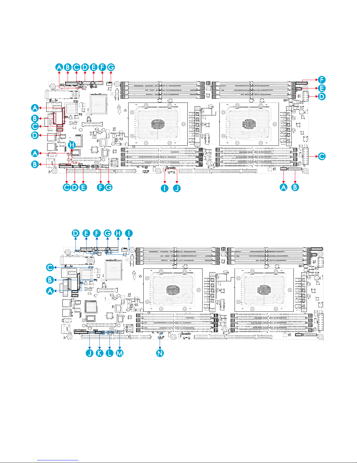
3�2 Motherboard Layout
J10
J37
J20
J43
J17
J23
J15
J21
J35
J48
J31J31
J30
J30
J30
J31
J44
J52
J13
J7
J12
J11
J39
J36
J49
J14
J9
J18
J27
J24J24
J2002
J2001
J47
J16
J34
J42
J22
J51
J33
J86
J87
J85
J40
J81J45
Page 18

Chapter 3 Motherboard Setting
13
Pavo User's Manual
3�3 Motherboard Content List
Connectors Location Connectors Location
1 Power Supply
J87:12V & 5VSB
6A per pin.
23
ME Recovery
Mode
J35
2 Power Supply J86:12V 24
AIC OPEN RACK
Header
J40
3 Serial ATA J33, J34 25 FAN Front J39
4 Serial ATA J32 26 MDI PHY Front J85
5 Front Panel J81 27
SATA-DOM
Power
J22, J42
6 VGA J7 28 LCM J9
7 COM1 J11 29 SGPIO J18
8 COM4 J12 30 SSGPIO J27
9 Front USB 3.0 J16 31 BMC Disable J30
10 Front USB 2.0 J49 32 Password Clear J31
11 DIMM Slots
J56~J58, J61~J65,
J69~J76
33 PECI J44
12 CPU Sockets U55, U78 34 VRM SMB J24
13 Debug Port J13 35 All Node OFF J52
14 BMC Debug Port J14 36 PMBUS J45
15 Clear CMOS JJ10 37 BMC FAN J51
16 BMC IPMB J36 38
SATA DOM Set
Up
J20, J43
17 Battery Socket BAT1 39
BIOS Recovery
Mode
J37
18 Intruder J47 40 UART J17
19 SPI ROM Socket U25 41 BMC RESET J23
20 BMC ROM Socket U29 42 UID LED J15
21 Speaker J48 43
PCIE Hot-Plug
SMB (CPU0)
J2001
22
FLASH Security
override
J21 44
PCIE Hot-Plug
SMB (CPU1)
J2002
Page 19

Chapter 3 Motherboard Setting
14
Pavo User's Manual
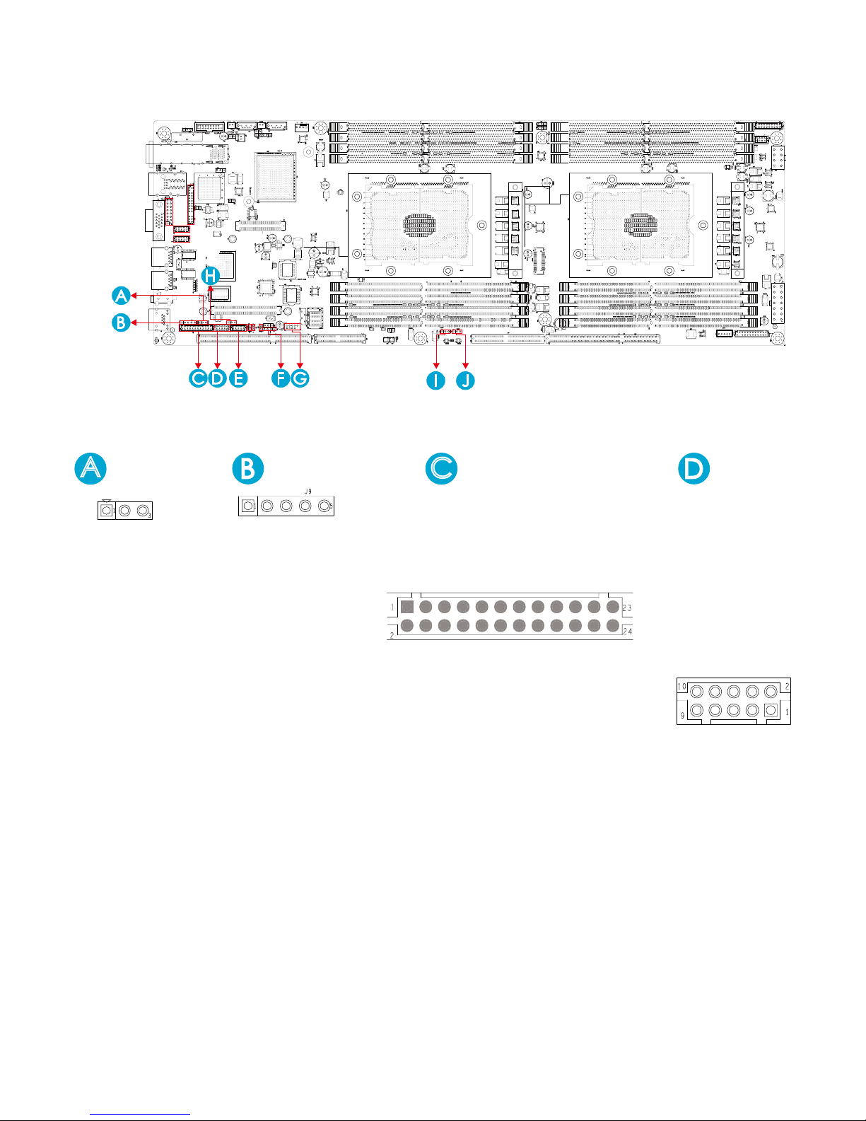
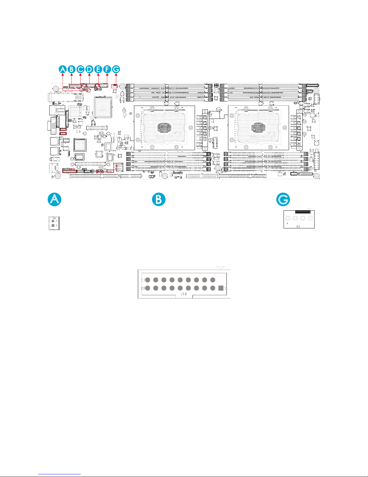
3�4 Internal Connectors/Jumpers
J13
J7
J12
J11
J14
GND
GND
AVSYNCO
NC
GND
DDC_DATAO
DACGO
GND
DDC_CLKO
GND
VGA_5V
AHSYNCO
DACBO
GND
NC
DACRO
J7
GND
KEY
P5V
PCH_IO2
PCH_IO1
GND
SMB_PCH_SDA
ESPI_CS1
PCH_CLKRUN
ESPI_ALERT0
KEY
P3V3
ESPI_PME
ESPI_SEL
CLK_DP80
PCH_CS0_N
RST_PERST_N
PCH_ IO3
P3V3
PCH _IO0
SMB_PCH_SCL
P3V3_AUX
GND
ESPI_RESET
KEY
ESPI_ALERT1
ESPI_SMI
P5V_AUX
J13
A
DSR
RTS
CTS
RI
NC
DCD
RXD
TXD
DTR
GND
J12
DSR
RTS
CTS
RI
NC
DCD
RXD
TXD
DTR
GND
J11
TXD
RXD
GND
J14
E
Page 20
Chapter 3 Motherboard Setting
15
Pavo User's Manual
Internal Connectors/Jumpers
J39
J36
J49
J14
J9
J18
J27
J24J24
J2002
J2001
GND
COM_OUT_RXD4
COM_OUT_TXD4
FP_RSTBTN_N
FP_PWRBTN_N
J9
GND
FAN_PWM5
FAN_PWM4
FAN_PWM3
FAN_TACH11
FAN_TACH10
FAN_TACH9
FAN_TACH8
FAN_TACH7
FAN_TACH6
I2CSCL
GND
GND
FAN_PWM2
FAN_PWM1
FAN_PWM0
FAN_TACH5
FAN_TACH4
FAN_TACH3
FAN_TACH2
FAN_TACH1
FAN_TACH0
I2CSDA
+3.3V_DUAL
J39
C
FM_SGPIO0_I2C_A0
FM_SGPIO0_I2C_A1
I2C14SCL
I2C14SDA
GND
P3V3_AUX
SGPIO_SATA0_DATA1
SGPIO_SATA0_DATA0
SGPIO_SATA0_LOAD
SGPIO_SATA0_CLOCK
J18
J18
J14
A
GND
RXD
TXD
J14
Page 21
Chapter 3 Motherboard Setting
16
Pavo User's Manual
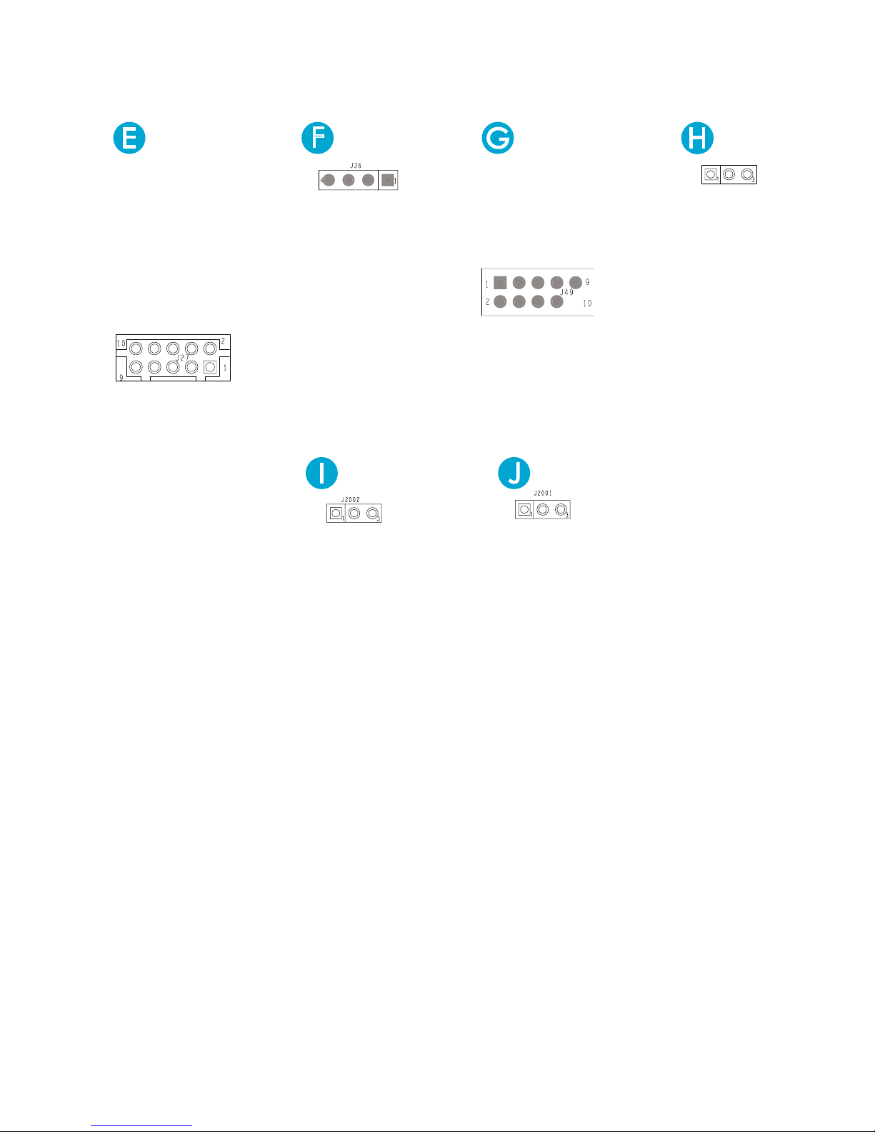
Internal Connectors/Jumpers
FM_SGPIO1_I2C_A0
FM_SGPIO1_I2C_A1
I2C14SCL
I2C14SDA
GND
P3V3_AUX
SGPIO_SSATA0_DATA1
SGPIO_SSATA0_DATA0
SGPIO_SSATA0_LOAD
SGPIO_SSATA0_CLOCK
J27
I2C1SDA
GND
I2C1SCL
NC
F
J36
KEY
GND
USB2_P6
USB2_N6
VDD_USB_P56
GND
GND
USB2_P5
USB2_N5
VDD_USB_P56
J49
J24
SMB_VR_SCL
GND
SMB_VR_SDA
J24
SMB_PEHPCPU0_DAT
GND
SMB_PEHPCPU0_SCL
J2002
SMB_PEHPCPU1_DAT
GND
SMB_PEHPCPU1_SCL
J2001
Page 22
Chapter 3 Motherboard Setting
17
Pavo User's Manual
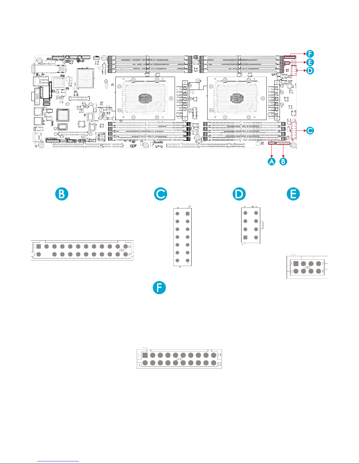
Internal Connectors/Jumpers
J47
J16
J34
J42
J22
J51
J33
GND
INTRUDER
J47
A
J16
VDD_USB_P34
USB3_RX_N2
USB3_RX_P2
GND
USB3_TX_N2
USB3_TX_P2
GND
USB2_N2
USB2_P2
PCH_USB_OC#23
KEY
VDD_USB_P34
USB3_RX_N3
USB3_RX_P3
GND
USB3_TX_N3
USB3_TX_P3
GND
USB2_N3
USB2_P3
J51
G
GND
P12V
TACH
PWM
Page 23
Chapter 3 Motherboard Setting
18
Pavo User's Manual
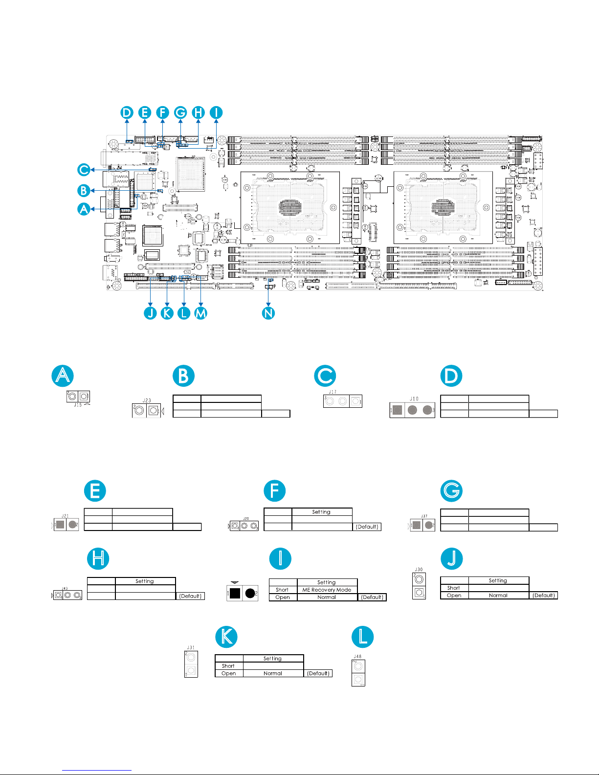
Internal Connectors/Jumpers
CHASSIS_1U2N_N
BNC_GPIO_EXIN
FAN_TACH1
FAN_PWM1
GND
FAN_TACH0
FAN_PWM0
GND
I2C8SDA
I2C8SCL
GND
INTRUDER_N
PMBUS_ALERT_N
PMBUS_DATA
PMBUS_CLK
GND
I2C1SDA
I2C1SCL
GND
BMC_RESET_N
J40
J86
J87
J85
J40
J81J45
UID_BTN
NC
NMI_BTN
GND
RST_BTN
GND
PWR_BTN
HD_LED-
HD_LED+
PWR_LED-
KEY
PWR_LED
LAN2_ACT -
LAN2_ACT +
INTRUDER_N
I2CCL
I2CDA
LAN1_ACT -
LAN1_ACT +
FAUL_TLED
FAUL_TLED+
UID_LED -
UID_LED +
+3.3V_DUAL
J81
GND
GND
GND
GND
GND
GND
PS_ON#
J87
+12V
+12V
+12V
+12V
+12V
+5V_AUX
POWER OK
GND
GND
GND
GND
J86
+12V
+12V
+12V
+12V
MDI1_DATA_R_N
MDI1_DATA_R_P
MDI0_DATA_R_N
MDI0_DATA_R_P
MDI3_DATA_R_N
MDI3_DATA_R_P
MDI2_DATA_R_N
MDI2_DATA_R_P
J85
Page 24
Chapter 3 Motherboard Setting
19
Pavo User's Manual
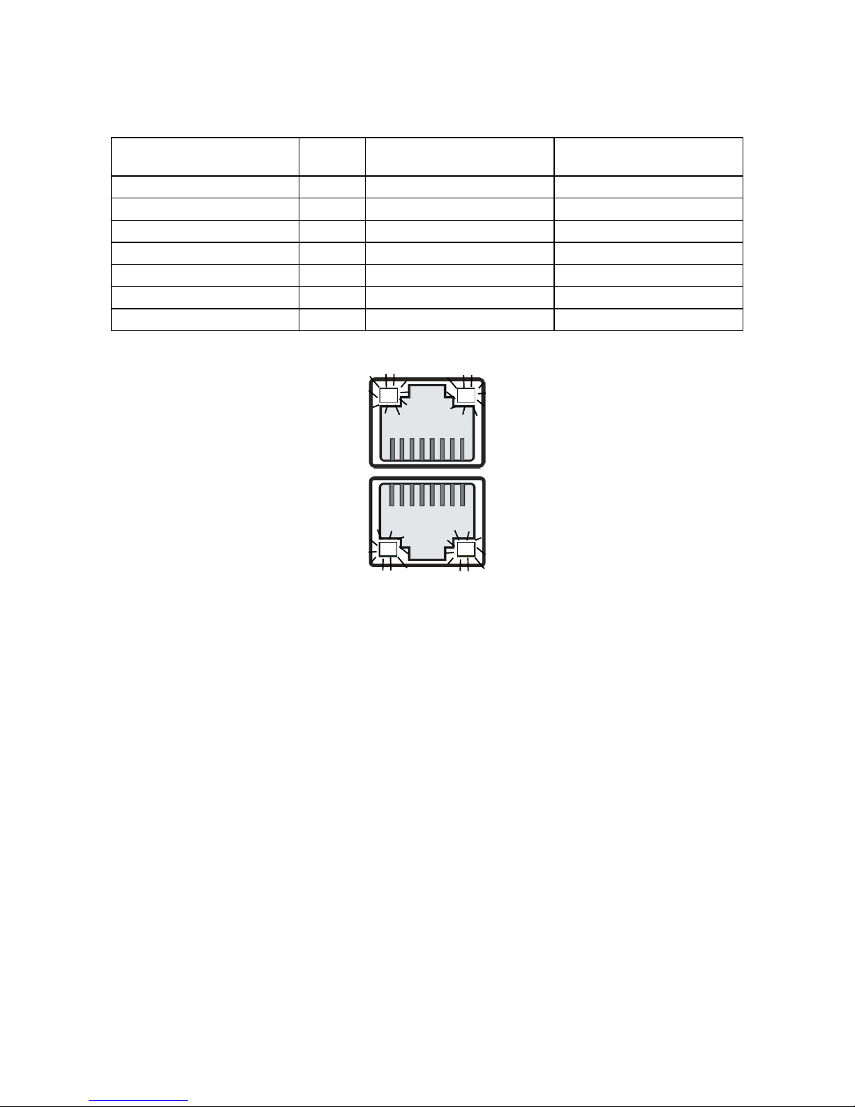
Internal Connectors/Jumpers
J10
J37
J20
J43
J17
J23
J15
J21
J35
J48
J31J31
J30
J30
J30
J31
J44
J52
A
J15
P5V_AUX
UID_LED
UART_TX
GND
UART_RX
J17
J20
SATA
SATA DOM
J20
Pin1-2
Pin2-3
J43
SATA
SATA DOM
J43
Pin1-2
Pin2-3
H
J35
J35
I
J30
J
J30
BMC Disable
J31
K
J31
Password Clear
J48
L
+5V
SPEAKER
(Default )
J10S etti ng
Pin1-2 Normal
Clear CMOS
Pin2-3
J10
(Default )
J23S etti ng
Short
Open Normal
BMC Reset
J23
(Default )
J21
Short FLASH Security override
Normal
Setting
Open
J21
(Default )
J37
Short BIOS Recovery Mode
Setting
NormalOpen
J37
G
Page 25

Chapter 3 Motherboard Setting
20
Pavo User's Manual
3�5 LEDs
3.5.1 Front Panel LED Denition
Power
Yellow System is On
Blinking
System is in Standby; System is
off, but has AC power
Off System has no AC power
UID
Blue UID activity detected
Off No UID activity detected
System Fault
Red
Critical system failure detected
(processors, memory, voltage
regulators, thermal events,fan
failures, NMI, etc)
Off No critical failures detected
Hard Disk
Green (Blinking) Disk activity detected
Off No disk activity detected
LAN1_TRAFFIC
Green (Blinking) LAN1 activity detected
Off LAN1 is not active
LAN2_TRAFFIC
Green (Blinking) LAN2 activity detected
Off LAN2 is not active
Page 26
Chapter 3 Motherboard Setting
21
Pavo User's Manual
3.5.2 Rear I350 LAN LEDs
The NIC Port LED should be connected to Vaux (standby) voltage.
Description
Left LED (LED4, LED2,)
(Link/Activity)
Right LED (LED3, LED1,)
(Speed)
No Link OFF OFF
Linked at 10 Mbps Link Green OFF
Active Blinking Green OFF
Linked at 100 Mbps Link Green Green
Active Blinking Green Green
Linked at 1000 Mbps Link Green Yellow
Active Blinking Green Yellow
LED1
LED3LED4
LED2
Page 27

Chapter 3 Motherboard Setting
22
Pavo User's Manual
3.5.3 BMC LEDs
BMC LED Denition
LED5
Green LAN1 activity detected
OFF LAN1 is not active
LED7
Yellow
(Blinking)
LAN1 Link detected
OFF LAN1 is not Link
LED6
Green LAN0 Link detected
OFF LAN0 is not Link
LED4
Yellow
(Blinking)
LAN0 activity detected
OFF LAN0 is not active
LED7 LED6
LED4LED5
Page 28

Chapter 3 Motherboard Setting
23
Pavo User's Manual
3.5.3 Rear PCH LAN LEDs
SFP LED Denition
LED1
ON UID activity detected
OFF UID is not active
LED2
ON
BMC Rack LAN activity detected
(Only for Rack)
OFF
BMC Rack LAN is not active
(Only for Rack)
LED3
ON
BMC Rack LAN activity detected
(Only for Rack)
OFF
BMC Rack LAN is not active
(Only for Rack)
LED18
Blinking BMC is working
OFF BMC not working
LED 2
LED 1
LED 3LED 3
LED 2
LED 1
LED 18
LED 18
Page 29

Chapter 4 BIOS Conguration and Settings
24
Pavo User's Manual
Chapter 4. BIOS Conguration and Settings
Press ESC to run the setup procedure.
Caution: When Quiet Boot IS enabled, OEM LOGO WILL BE displayed
INSTEAD OF POST MESSAGES.
There will be a message “Entering SETUP” displayed on the diagnostics screen.
Caution: For the official released version, the last digit of the
BIOS Version must end in an "0."
Page 30
Chapter 4 BIOS Conguration and Settings
25
Pavo User's Manual
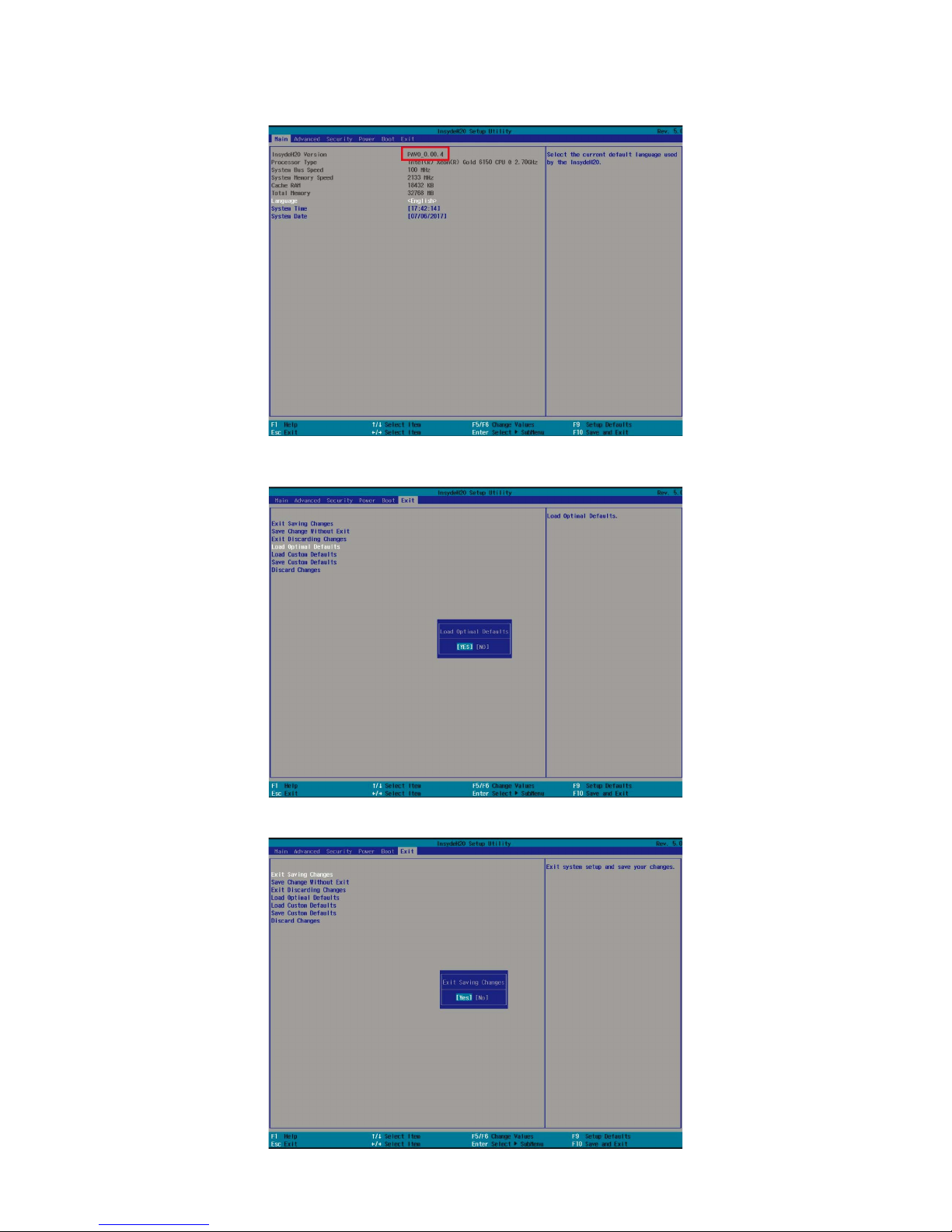
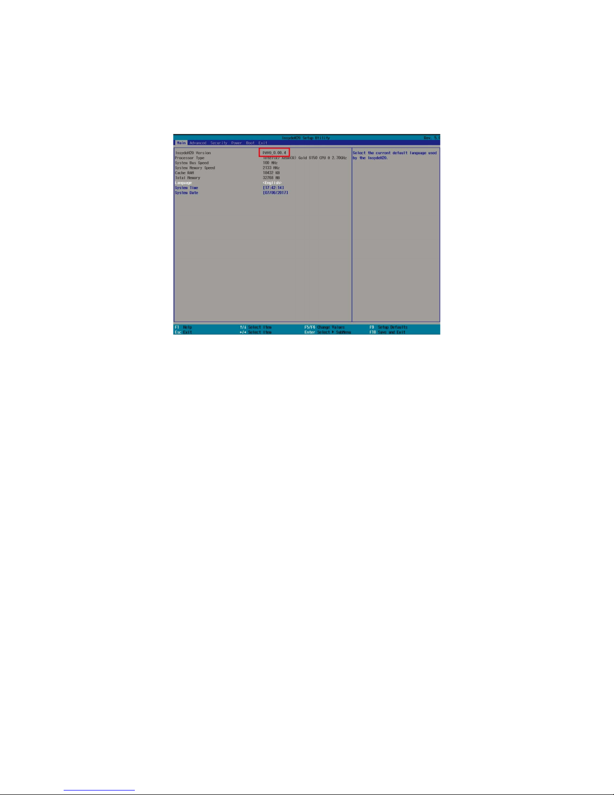
Identify the BIOS Version
Load Optimal Default setting
Save the setting and exit the BIOS setup utility.
Page 31
Chapter 4 BIOS Conguration and Settings
26
Pavo User's Manual
4�1 Updating BIOS
Important Notes:
To identify the current BIOS version, please check out on BIOS setup.
Page 32
Chapter 4 BIOS Conguration and Settings
27
Pavo User's Manual
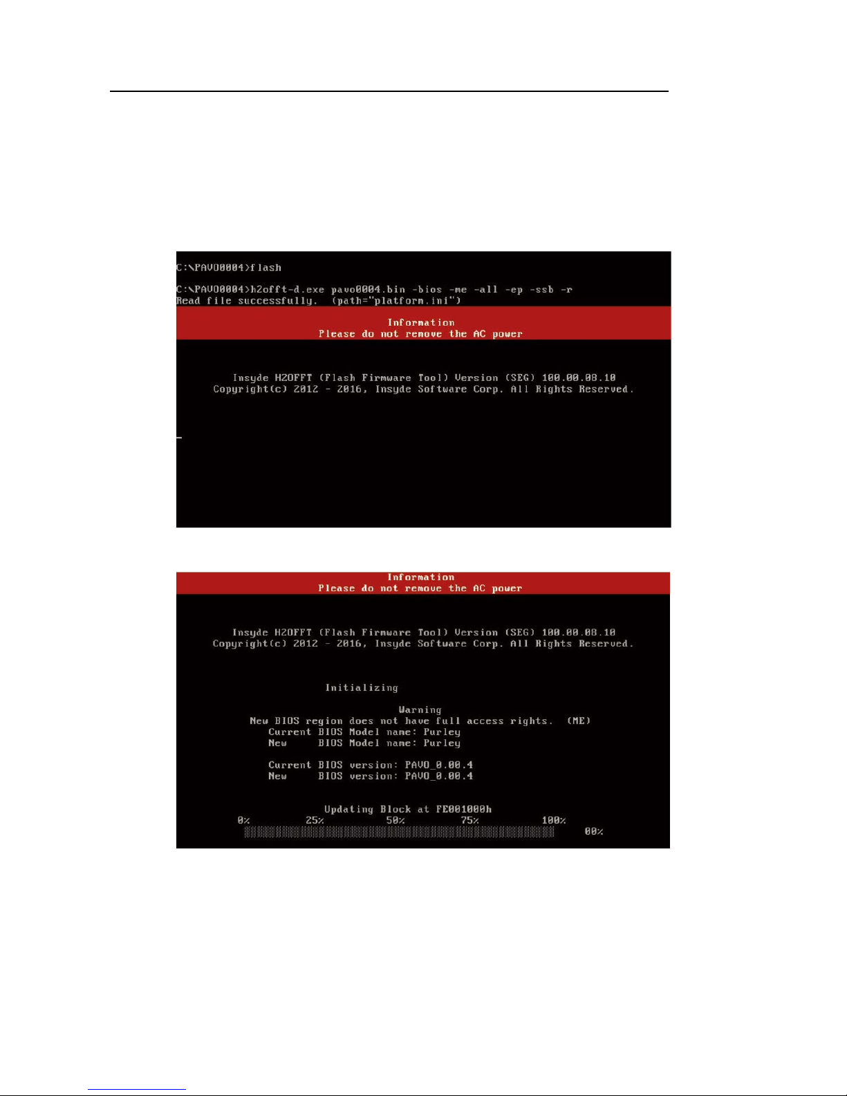
Update BIOS by INSYDE H2OFFT-D utility under DOS environment
If you need to update Flash in the DOS environment, please use
H2OFFT-D utility. To use this utility, you must include the ash.bat
, H2OFFT-D.exe, and bin le in the same folder. Please follow the
instructions to update whole ash part:
Execute ash.bat to update Flash in the DOS environment.
Reboot system.
Page 33
Chapter 5 BMC Conguration and Settings
28
Pavo User's Manual
Chapter 5. BMC Conguration and Settings
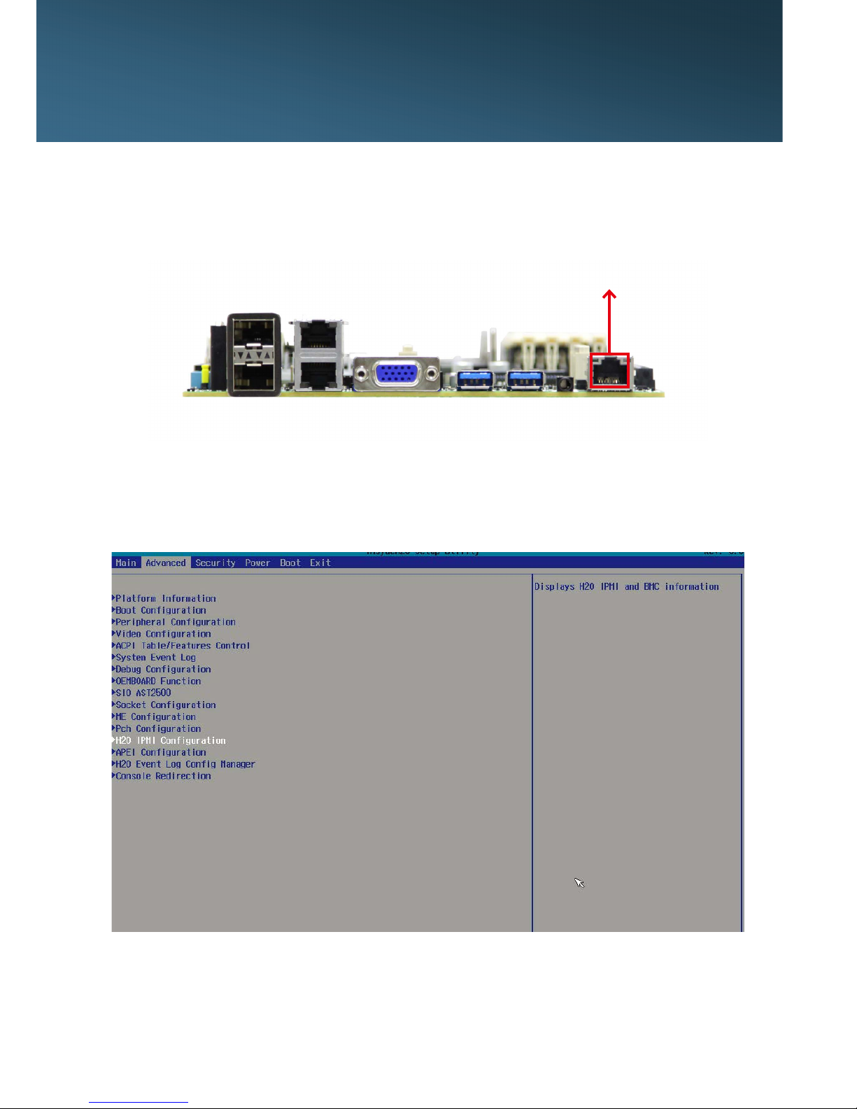
Insert Ethernet LAN cable into the BMC LAN port. There are two
methods to setup BMC IP:
5�1 Method 1 (Use the BIOS setup)
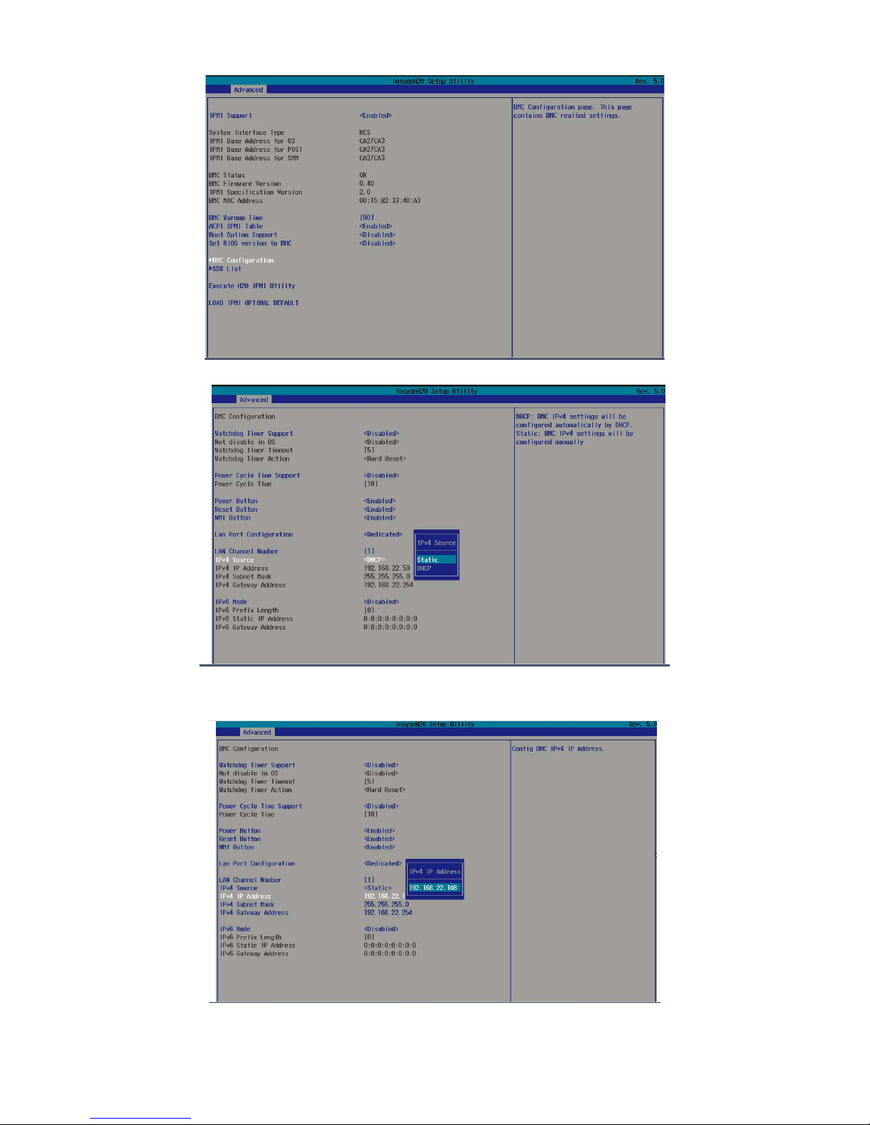
• BIOS SETUP Advanced H2O IPMI configuration
BMC
Conguration IPv4 source Static
BMC management port
Page 34
Chapter 5 BMC Conguration and Settings
29
Pavo User's Manual
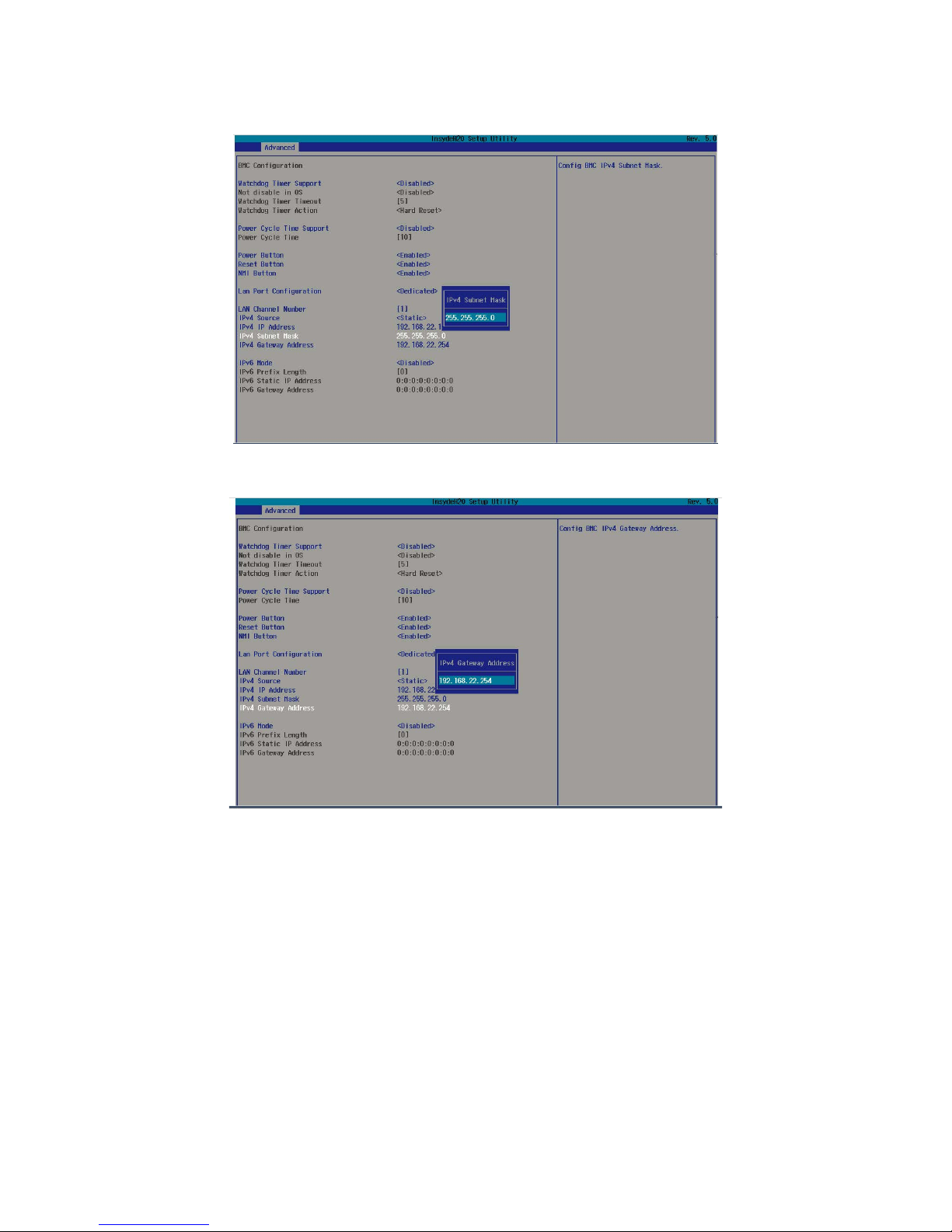
1. Input IP address. Set static IP.
Page 35
Chapter 5 BMC Conguration and Settings
30
Pavo User's Manual
2. Input subnet mask address.
3. Input gateway address.
Page 36

Chapter 5 BMC Conguration and Settings
31
Pavo User's Manual
5�2 Method 2 (Use a Dos tool - Syscheck)
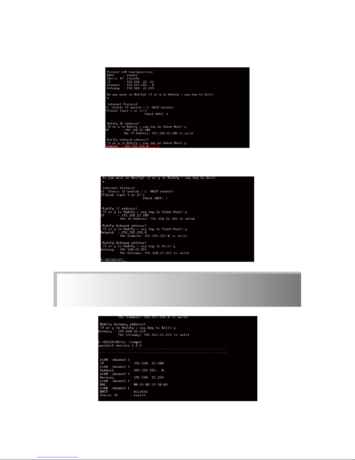
1. Type : sc –lanset
2. Modify IP setting
3. Input IP address
Note: type 1 for selecting static IP mode or type 2 for selecting
DHCP mode.
Page 37
Chapter 5 BMC Conguration and Settings
32
Pavo User's Manual
4. Input submask address.
Below IP address is an example using a default IP setting. User is
allowed to change the IP address for realistic use.
5. Set gateway address, nish BMC IP conguration.
Note: Type sc.exe –langet command to obtain BMC IP and MAC
address.
Page 38
Chapter 5 BMC Conguration and Settings
33
Pavo User's Manual
5�3 Connect to BMC
Below IP address is an example using default IP setting. User is
allowed to change the IP address for realistic use.
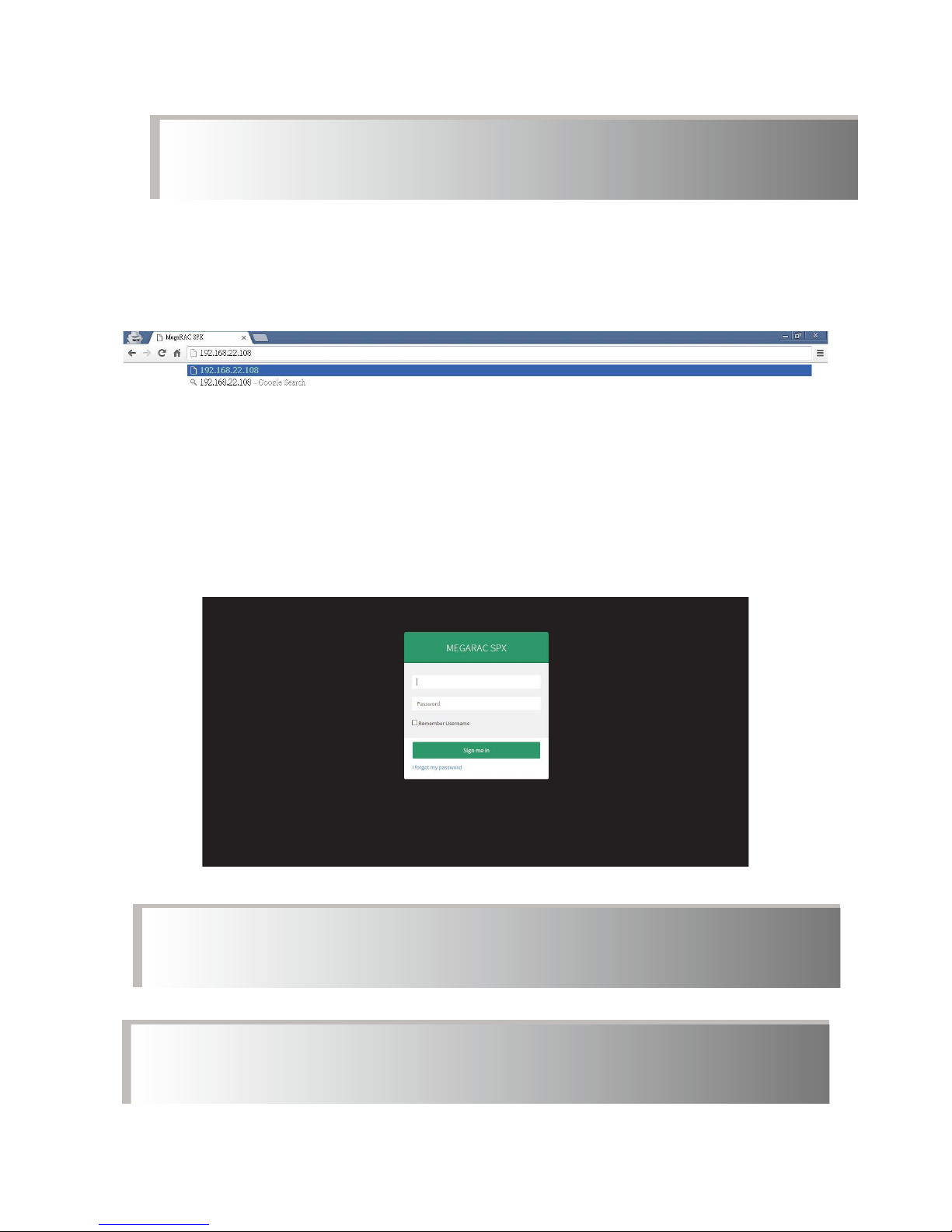
1. Open the browser then type default BMC IP address:
192.168.22.108
2. Use the default user name and password for rst-time login to BMC
WEB GUI.
Field: Default
UserName: admin
Password: admin
note :
This feature works with JAVA 6 runtime installed console environment.
note :
The default user name and password are in lower-case characters.
note :
Users who login with the root user name and password will have full
administrative power. The root password can be changed after login.
Page 39
Chapter 5 BMC Conguration and Settings
34
Pavo User's Manual
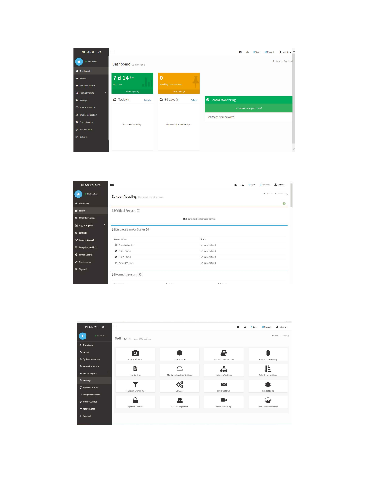
3. Information of rmware.
4. Server Health - Sensor Readings:
5. Configuration:Please refer to AIC BMC User Guide for more
information on AIC BMC.
Page 40
Chapter 5 BMC Conguration and Settings
35
Pavo User's Manual
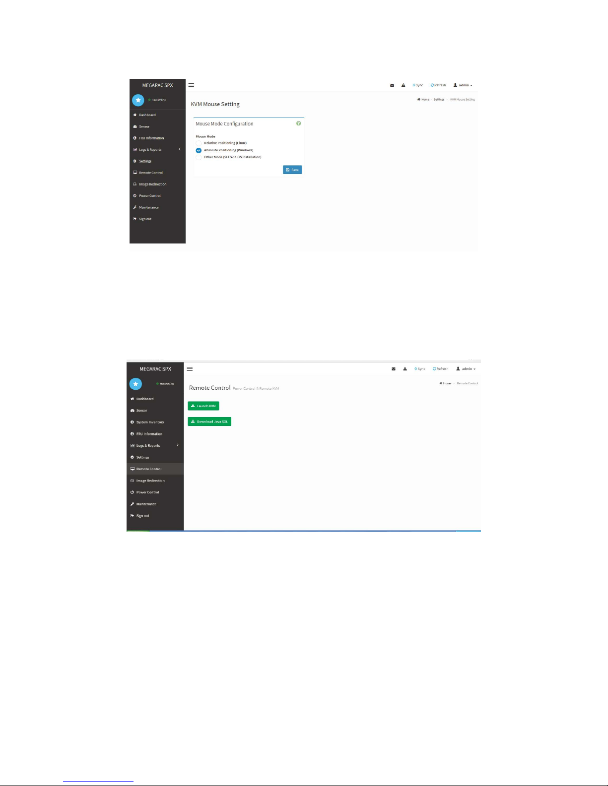
Mouse Mode setting:
• For Windows OS environment, set mode to absolute.
• For Linux OS environment, set mode to relative.
• For SLES-11 OS environment, set mode to other mode.
6. Remote Control:
Page 41
Chapter 5 BMC Conguration and Settings
36
Pavo User's Manual
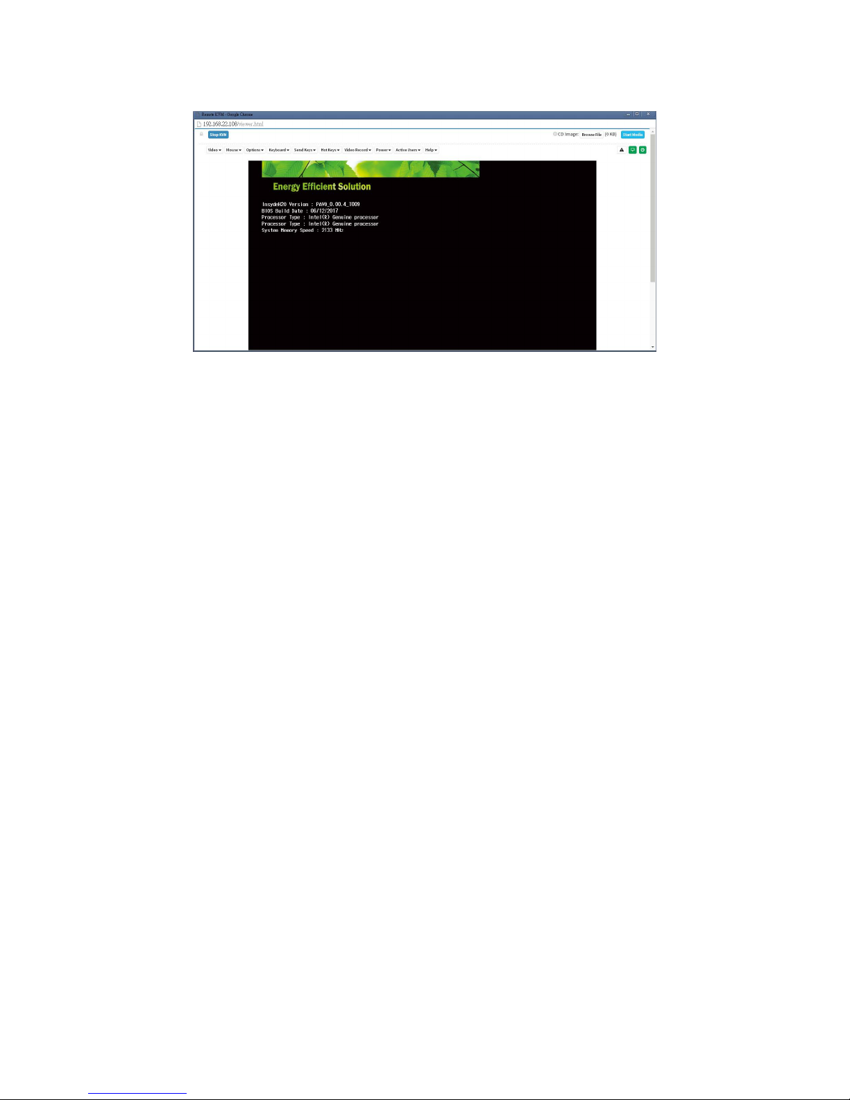
Launch KVM
:
Page 42

Chapter 5 BMC Conguration and Settings
37
Pavo User's Manual
5�4 Updating BMC Firmware
1. Boot to the DOS (MS-DOS or Free DOS is workable)
2. Enter BMC firmware directory [XXXXZYYY]; XXXX: project name
;YYY: firmware version; Z: Identify character, C for official, B for
Beta.
Execute a�bat batch le to update the BMC rmware
Example:
A:>cd PAVOC01
A:\ PAVOC01>a.bat
This is just an example. The latest BMC rmware version is available
from the FAE or AIC website.
3. After update BMC rmware, please power off and then power on
system.
Notes:
1. DO NOT USE EMM386 IN DOS ENVIRONMENT WHEN UPDATING
FIRMWARE OR YOU WILL GET A FAIL.
2. IN SOME CRITICAL CONDITION, AFTER UPDATING BMC
FIRMWARE OR CONFIG FILE, YOU MIGHT NEED TO UNPLUG
AC POWER CORD 5 SECONDS AND THEN PLUG AC POWER
CORD TO RESET BMC, THEN UPDATED NEW FUNCTION CAN
WORK PROPERLY.
Page 43

www�aicipc�com
• TAIWAN
Tel: +886 3 433 9188
Fax: +886 3 287 1818
Email : sales@aicipc�com�tw
• CHINA
Tel: +86�21�54961421, +86�21�54961422
Fax: Extension: 608
Email Technical Support: support@aicipc�com
• AMERICA - West coast
Tel: +1�909�895�8989
Fax: +1�909�895�8999
Email : sales@aicipc�com
• AMERICA - East coast
Tel: +1�973�884�8886
Fax: +1�973�884�4794
Email : [email protected]
• EUROPE
Tel: +31�30�6386789
Fax: +31�30�6360638
Email:sales@aicipc�nl
Email Technical Support: support@aicipc�com
Chapter 6� Technical Support
 Loading...