

AIC AIC1863CS, AIC1863 Datasheet
AIC1863
876
5
I R Preamplifier for Remote Control System
FEATURES
n
l Only Two External Components Required Other
than the Photodiode.
l Easy to Integrate into Module due to Small Chip
Size.
l Minimized Chances of Malfunction Due to Am-
bient Light.
l Low Power Consumption.
l Center Frequency of Band Pass Filter Adjusta-
ble by an External Resistor.
l Microcomputer Compatible.
APPLICATIONS
n
l IR Remote Control Receivers for Consumer
Electronic Products, such as TVs, VCRs,
VCD/DVD Players, Audio Devices, Air Conditioners, Electric Fans ...etc.
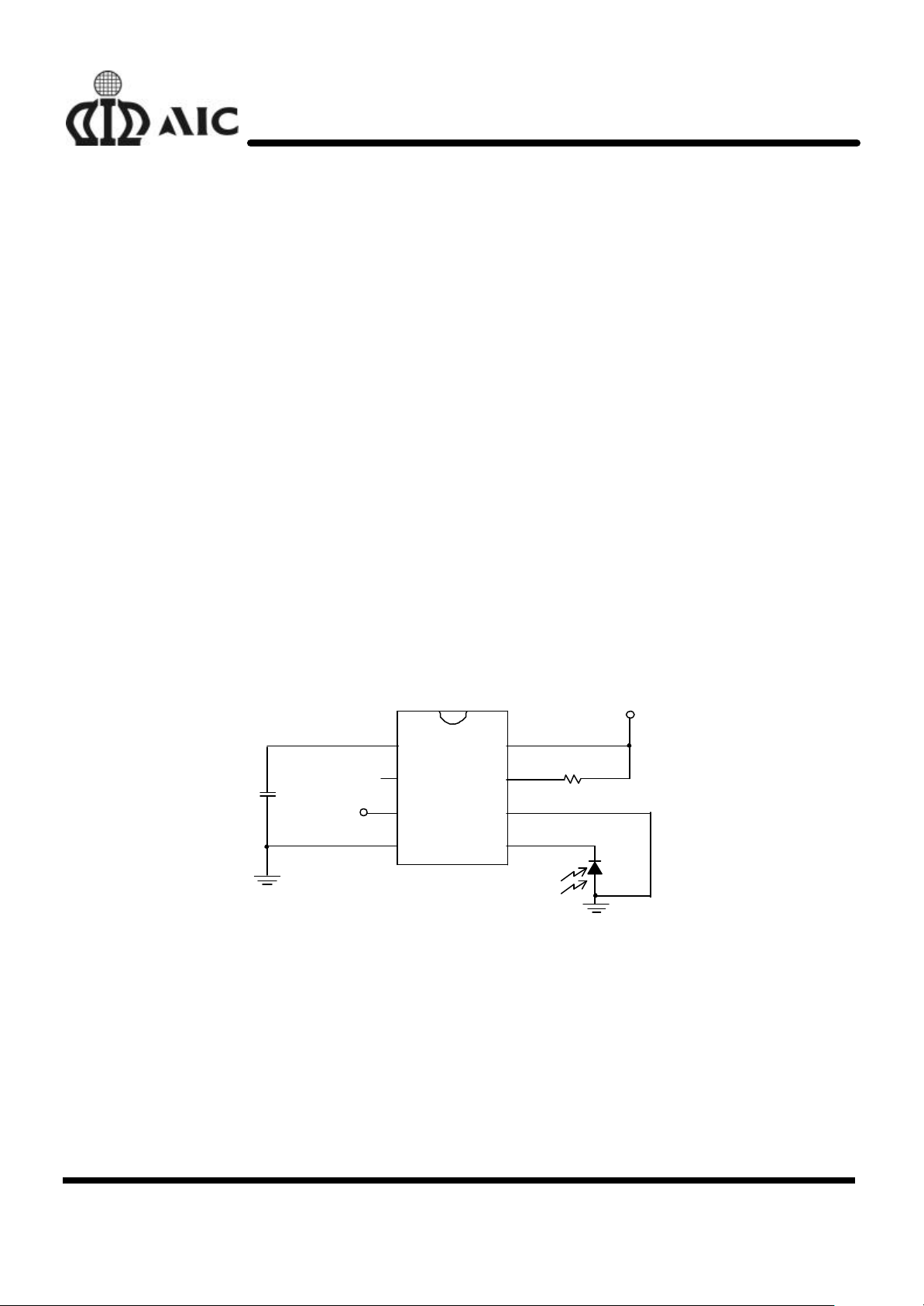
TYPICAL APPLICATION CIRCUIT
n
DESCRIPTION
n
The AIC1863 is a high performance infrared remote control preamplifier. Especially, it has excellent interference suppression capability. The
infrared pulses arriving at the photodiode are
treated by the trans-impedance amplifier and
amplified by the auto-gain control amplifier, limitter amplifier, and band-pass filter. The following
evaluation circuits, including the comparator, integrator, and schmitt-trigger, demodulate the
transmitted digital signal. Reduction of sensitivity
due to external interference is achieved by the
short-time boost and long-time control circuits,
which prevent interference voltages from affecting
the output.
C1
0.1µF
VOUT
ORDERING INFORMATION
n
1
CA
2
NC
3
OUT
4
DGND
AIC1863
IR Remote Control Receiver
VCC
FO
AGND
IN
Vcc (+5V)
R1
110K(fo =38KHz)
Photo
Diode
Analog Integrations Corporation 4F, 9, Industry E. 9th Rd, Science Based Industrial Park, Hsinchu Taiwan, ROC
www.analog.com.tw
DS-1863-00 TEL: 886-3-5772500 FAX: 886-3-5772510 1
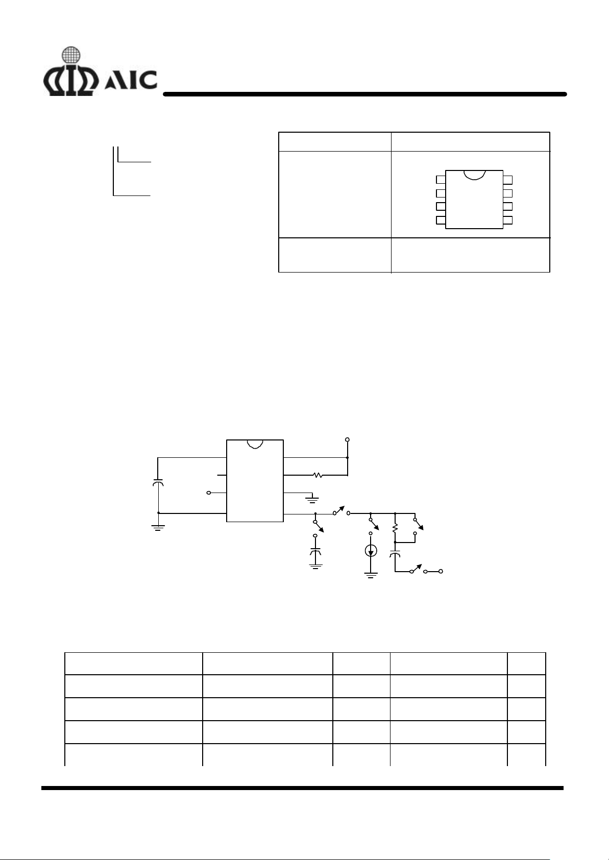
AIC1863 XX
ORDER NUMBER
PIN CONFIGURATION
AGND
2
5
7
NC
OUT
DGND
+
110K
R1
IN
AGND
FO
DGND
OUTNCCA
876
321
VCC
C3
0.47µF
S5
S4
S3
100µAC20.47µF
47K
V
AIC1863
PACKAGE TYPE
S: SMALL OUTLINE
D: DICE
TEMPERATURE RANGE
C: 0°C~+70°C
AIC186 3CS
(PLASTIC SO)
TOP VIEW
CA
AIC186 3CD
(DICE)
ABSOLUTE MAXIMUM RATINGS
n
Supply Voltage ..................................................……………....................................... 5.5V
Input Voltage .......................................................……………................................. 5 Vp-p
Operating Temperature Range .....................................…………..................... -20°C~80°C
Storage Temperature Range .................................…………….................... - 65°C~ 150°C
TEST CIRCUIT
n
Vcc(+5V)
1
3
4
VCC
8
FO
6
IN
C1
VOUT
0.1µF
AIC1863
+
R2
IIN
+
S2
IN
S1
ELECTRICAL CHARACTERISTICS
n
(VCC= 5V, Ta=25°C, unless otherwise
specified.)
PARAMETER TEST CONDITIONS SYMBOL MIN. TYP. MAX. UNIT
Supply Voltage Vcc 4.5 5.0 5.5 V
Input Pin Voltage (1) IIN=0µA V
Input Pin Voltage (2) IIN=100µA V
Low Level Output Voltage V
IN1
IN2
OL
3.8 4.2 4.4 V
1.5 2.1 2.7 V
0.1 0.3 V
2
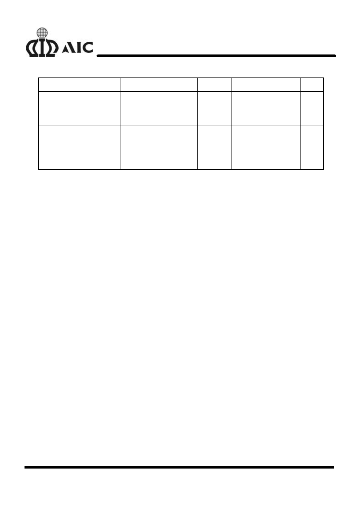
AIC1863
P-P
High Level Output Voltage V
Voltage Gain 100µV
BPF Characteristics
100µV
41KHz, 48KHz (note 1)
Input Impedance 0.5V
100µV
Detecting Ability (1)
600µS ON Time,
, 38KHz A
P-P
, 28KHz, 35KHz,
, 38KHz (note 2) R
P-P
, 38KHz
P-P
0.2 Duty Cycle
OH
V
A
Q
IN
T
D1
4.70 4.94 V
76 81 dB
4 9 dB
4 11 KΩ
360 520 680 µS
3
 Loading...