

AIC AIC1783CS, AIC1783 Datasheet
AIC1783
U2
C7
1000P
1DE2CF3
4
5
6IS7
8
R9
390K
D2
BATTERY
120K
D4
VIN
GNDU17805
Battery Charge Controller
FEATURES
n
l Fast Charge Control of NiMH/NiCd Batteries.
l Fast Charge Termination by: ?V− , ?V0 , Safety
Timer, Maximum Voltage.
l Protection against Battery Voltage Fault.
l Pulsed Trickle Charge Mode.
l Quick and Easy Testing for Production.
l 8-pin DIP or SO Packages.
APPLICATIONS
n
Battery Fast Chargers for:
l Mobile Phones.
l Notebook and Laptop Personal Computers.
l Portable Power Tools and Toys.
l Portable Communication Equipment.
l Portable Video & Stereo Equipment.
DESCRIPTION
n
The AIC1783 fast charge controller IC is designed
for intelligent charging of NiMH or NiCd batteries
without the risk of overcharge. ?V− detection
(-0.25%) and ?V0 detection (peak voltage timer)
are the primary methods employed by the
AIC1783 to terminate fast charge. The fast charge
can also be cut off by maximum battery voltage
along with the safety timer to prevent charging
under fault conditions of the charging system or
the battery itself.
The safety timer period is adjustable for flexible
usage that AIC1783 could be applied in the wide
range of battery capacity. Test mode is provided
for charger manufactures to dramatically reduce
production test time.
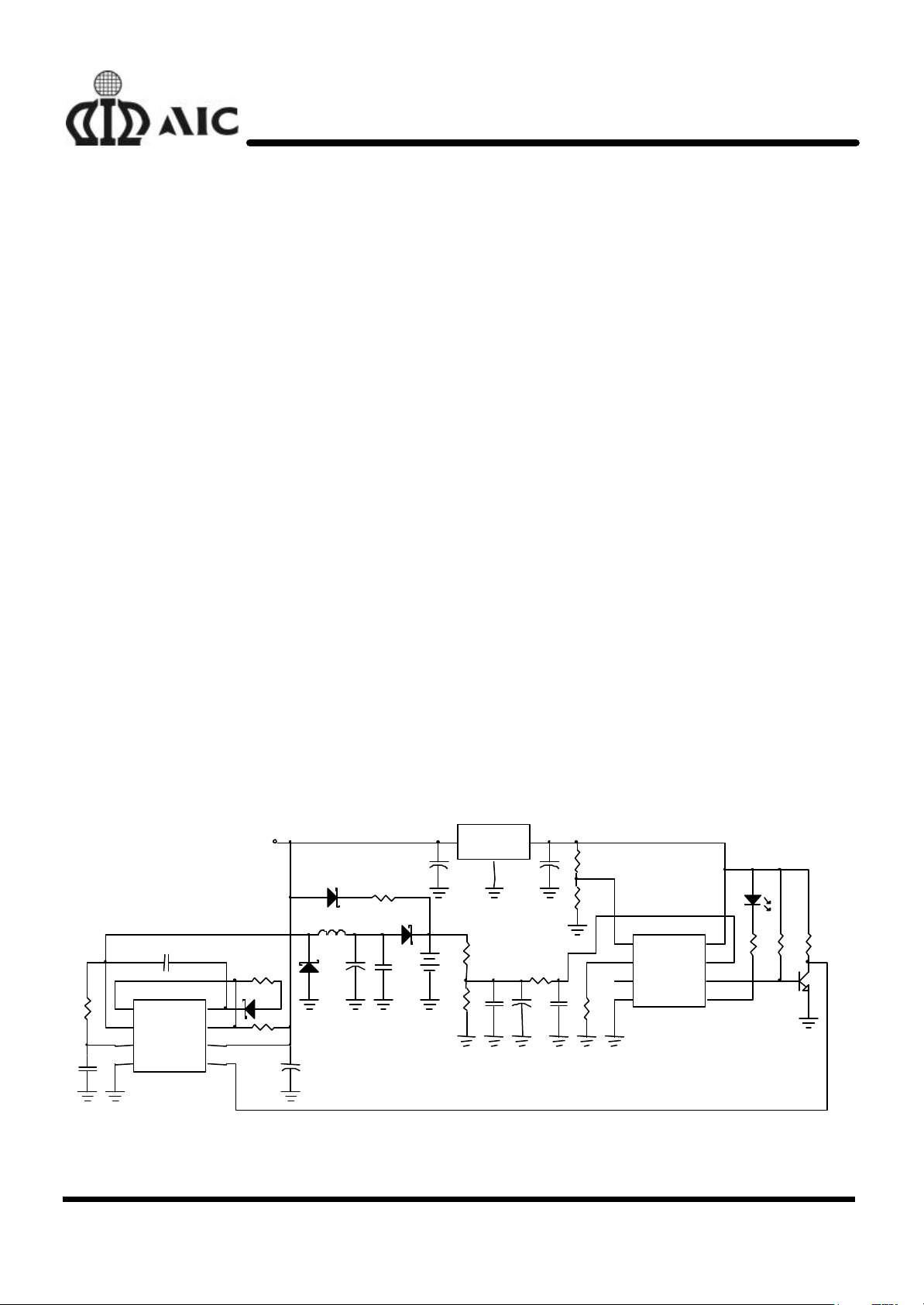
TYPICAL APPLICATION CIRCUIT
n
3
R2
240K
R5
2
0.1µF
VOUT
C4
R11 100K
+
C9
4.7µF
+ C6
10µF
C10
47nF
R3
100K
R4
120K
R12
150K
1
2
3
4
REF
TIMER
MODE
GND
AIC1783
VCC
VBT
ICON
LED
LED1
RED
8
7
6
5
680
R6
R7
47K
2N222
R8
10K
Q1
DC
GND
C1
AIC1563
1µF
U3
BOOST
VCC
VIN
1N4148
D3
220µH
L1
R13
120/0.5W
IN4148
R10
0.3/5W
FB
+
C8
220µF
D1
1N5822
+
C2
220µF
R1
1K
C3
0.1µF
C5
1µF
1N5822
+
BAT1
Battery Charge Circuit with Wide Input Voltage Range
Analog Integrations Corporation 4F, 9, Industry E. 9th Rd, Science Based Industrial Park, Hsinchu Taiwan, ROC www.analog.com.tw
DS-1783-00 May 28, 01 TEL: 886-3-5772500 FAX: 886-3-5772510 1
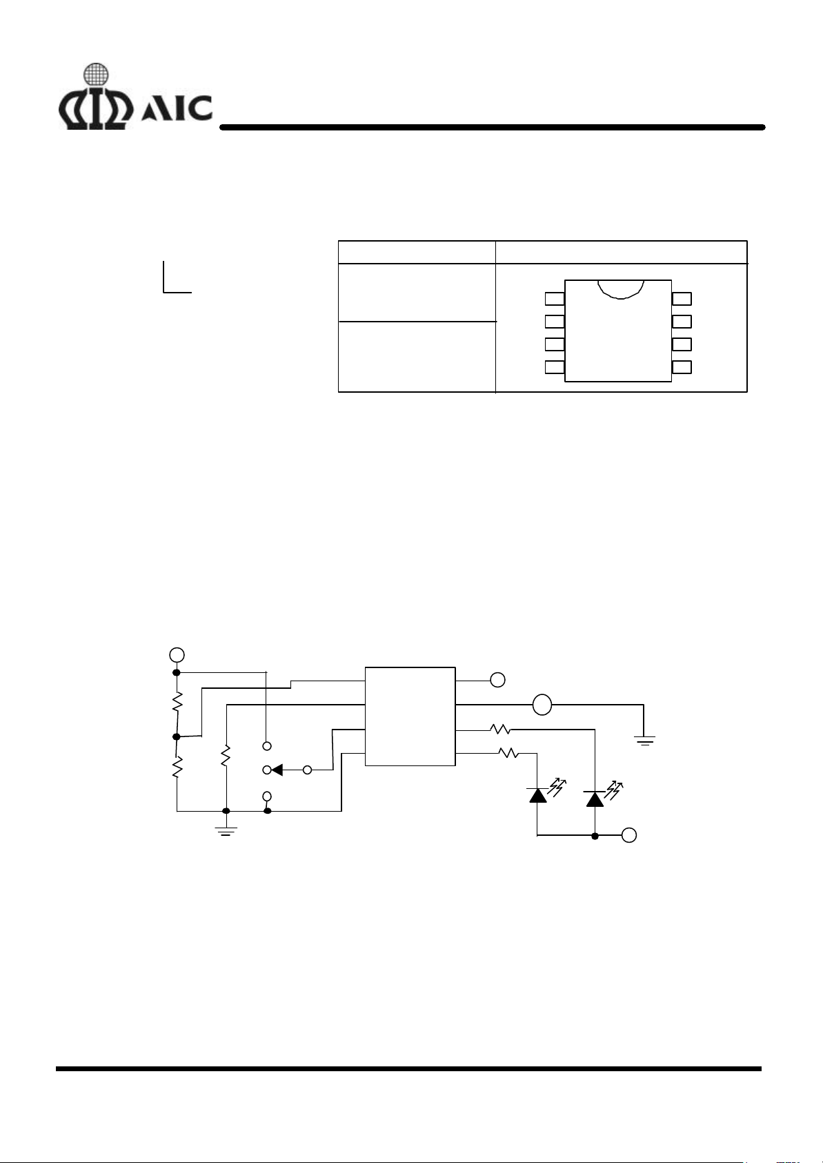
ORDERING INFORMATION
PACKAGE TYPE
ORDER NUMBER
AIC1783CN
PIN CONFIGURATION
AIC1783C
X
AIC1783CS
TIMER
+
100K
-
n
AIC1783
N: PLASTIC DIP
(PLASTIC DIP)
REF
S: SMALL OUTLINE
MODE
ABSOLUTE MAXIMUM RATINGS
n
(PLASTIC SO)
GND LED
Supply Voltage ............................................…………........................................ 5.5V
DC Voltage Applied on any pin ......................……………...................................... 5.5V
Sink current of ICON pin, LED1 and LED2 pin .......................……….................. 20mA
Operating Temperature Range .............................................………...... -40C~ 85°C
Storage Temperature Range .............................................…………...... -65°C~ 150°C
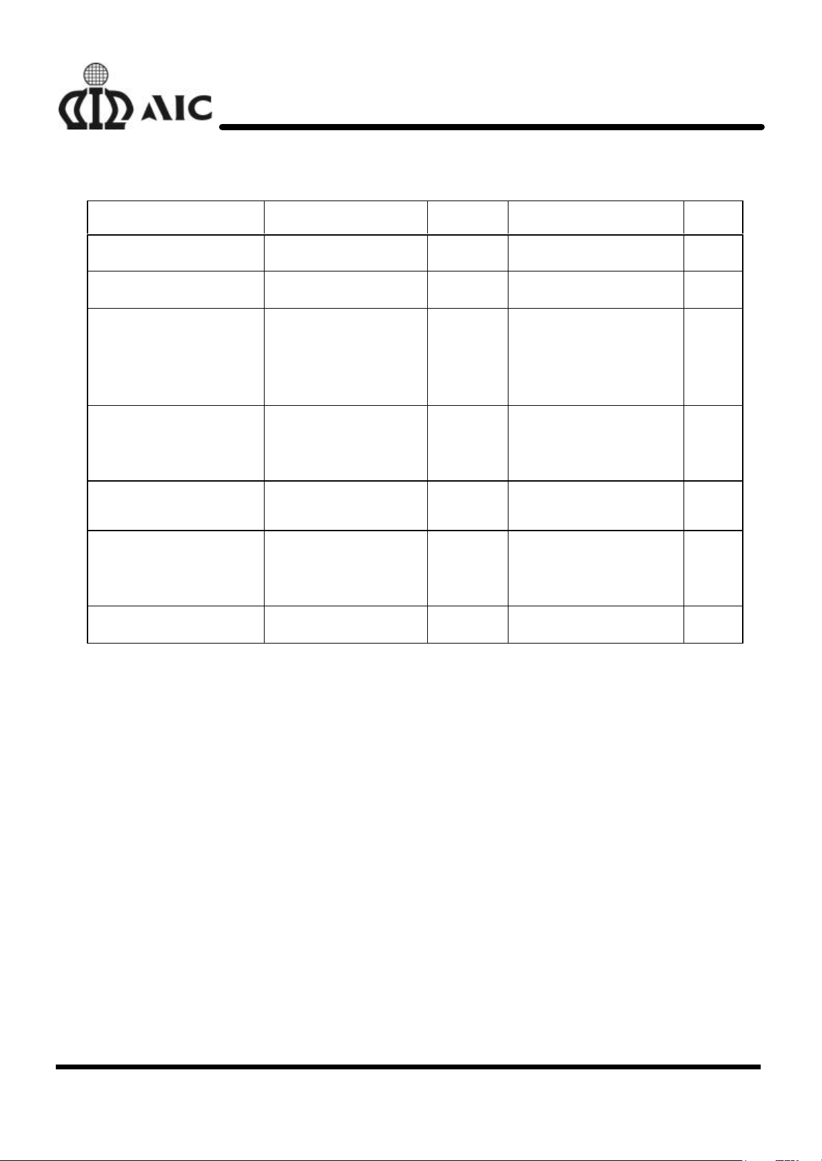
TEST CIRCUIT
n
5V
100K
120K
R
TIMER
1
2
3
4
TIMER
MODE
GND
AIC1783
VCCREF
VBT
ICON
LED
8
7
6
5
5V
680
680
1
2
3
4 5
VOLTAGE
SOURCE
8
7
6
VCC
VBT
ICON
RED
GREEN
5V
2
AIC1783
ELECTRICAL CHARACTERISTICS (Ta=25°C, V
n
PARAMETER TEST CONDITIONS SYMBOL MIN. TYP. MAX. UNIT
Supply Voltage V
Supply Current I
Battery Low
During Initial Timer
Voltage Protection Limit
Output Impe dance
Input Impedance MODE pin 300 KΩ
Recommended
External Resistor of
TIMER pin
After Initial Timer
Battery High
LED, ICON Pins
ON
OFF 1
VBT pin 1 MΩ
V
R
CC
CC
BT
TIMER
=5V, unless otherwise specified.)
CC
4.5 5.0 5.5 V
1.1 mA
0.11
0.63
2.6
2 100 1000 KΩ
0.16
0.69
2.7
25 50 Ω
0.21
0.75
2.80
V
MΩ
-∆V Detection accuracy VBT=2V -0.15 -0.25 -0.35 %
3
AIC1783
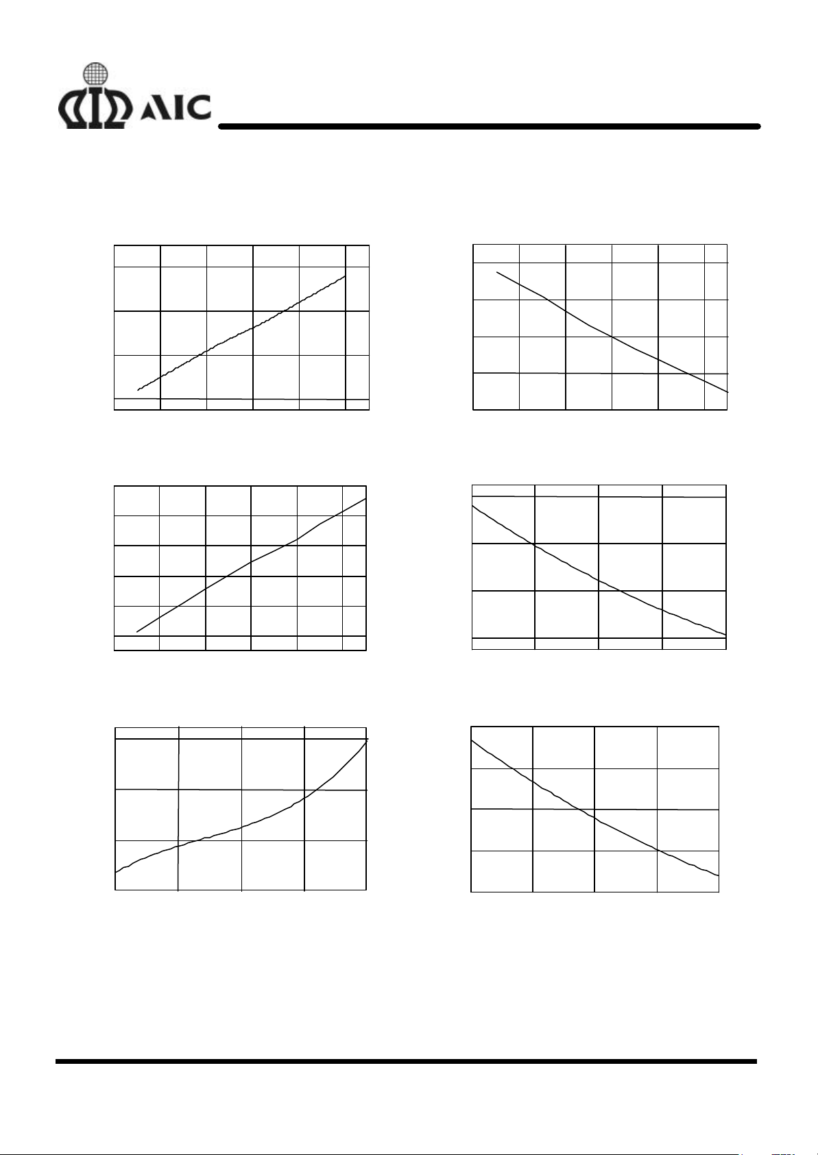
TYPICAL PERFORMANCE CHARACTERISTICS (Ta=25°C, R
n
VCC=5V, refer to Test Circuit)
1.21
1.18
1.12
1.06
Supply Current (mA)
1.00
4.4 4.6 4.8 5.0 5.2 5.4
VCC (V)
LED Flashing Frequency vs Supply Voltage
4.8
4.6
4.4
4.2
Frequency (Hz)
4.0
Supply Current vs Supply Voltage
81.0
80.5
80.0
Safety Timer (min.)
79.5
79.0
4.4 4.6 4.8 5.0 5.2 5.4
1.26
1.14
1.02
Supply Current (mA)
Safety Timer vs Supply Volatge
VCC (V)
Supply Current vs Temperature
TIMER
=100KΩ,
3.8
4.4 4.6 4.8 5.0 5.2 5.4
V
CC
(V)
Safety Timer vs Temperature
82.0
81.0
80.0
Safety Timer (min.)
79.0
0 20 40 60 80
Temperature(°C)
0.9
0 20 40 60 80
Temperature (°C)
LED Flashing Frequency vs Temperature
5.0
4.6
4.2
Frequency (Hz)
3.8
3.4
0 20 40 60 80
Temperature(°C)
4
 Loading...