

Page 1

Owner Instructions
Italiano 2
English 8
Français 14
Deutsch 20
Español 26
Portuguese 32
38
44
1
Page 2
2
Italiano
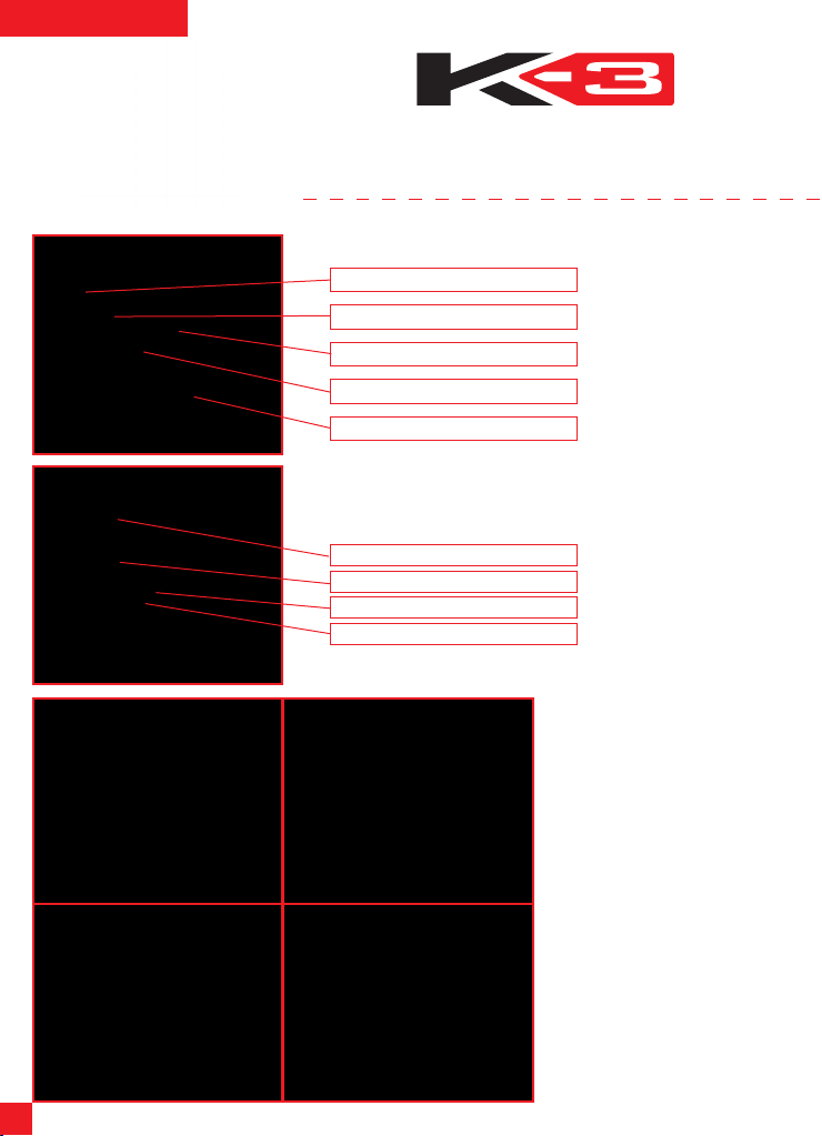
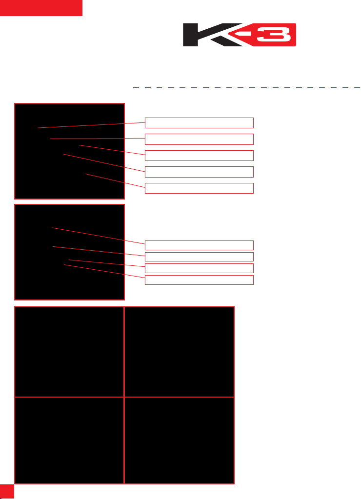
1) VISIERA
1 2
3 4
THIS HELMET’S SHELL IS MADE OF THERMOPLASTIC
THIS HELMET’S LINER IS MADE OF POLYSTIRENE (EPS)
1.1) Meccanismo Visiera
Sede innesto superiore
Fermo visiera 1
Fermo visiera 2
Denti base movimento
Cursore fermo visiera
1.2) Rimozione/Installazione Visiera
La visiera è in policarbonato antigraffio ed è dotata di innesti che si inseriscono nelle
sedi della base movimento. I denti della visiera interagiscono con i denti della base
movimento per consentire la stabilità in apertura della visiera nelle diverse posizioni.
Innesto superiore
Innesto inferiore 1
Denti visiera
Innesto inferiore 2
Vi consigliamo di eseguire le operazioni che seguono appoggiando il casco
su una superficie piatta.
Per rimuovere la visiera, ruotarla verso
l’alt o fino alla tota le a pe rtura (1).
Partendo da uno dei due lati del casco,
tirare verso il basso il cursore del fermo
visiera (2) ed estrarre gli innesti di
ag gan cio d ella vi sie ra. Ripe ter e
l’operazion e anche dall’altro l ato e
rimuovere la visiera.
Per installare la visiera, partendo da un
la to d el c asc o, con l a vi sier a
comp le tame nte sollevata, inser ire
l’innesto superiore della visiera nella sua
se de d ella base mov iment o (3 ).
Successivamente, inserire gli innesti
inferiori 1 e 2 della visiera nei rispettivi
fermi visiera (eventualmente aiutandosi
tirando verso il basso il cursore) (4).
Ripetere l’operazione anche dall’altro
lato. Abbassare la visiera e verificarne il
buon funzionamento.
NB Nel caso in cui la visiera non
aderisca perfettamente al profilo del
bordo del casco, potrebbe essere
ne ces sar ia una re gol azi one o
sostituzione della base meccanismo
visiera. In questo caso rivolgersi ad
un punto di assistenza AGV.
Page 3
3
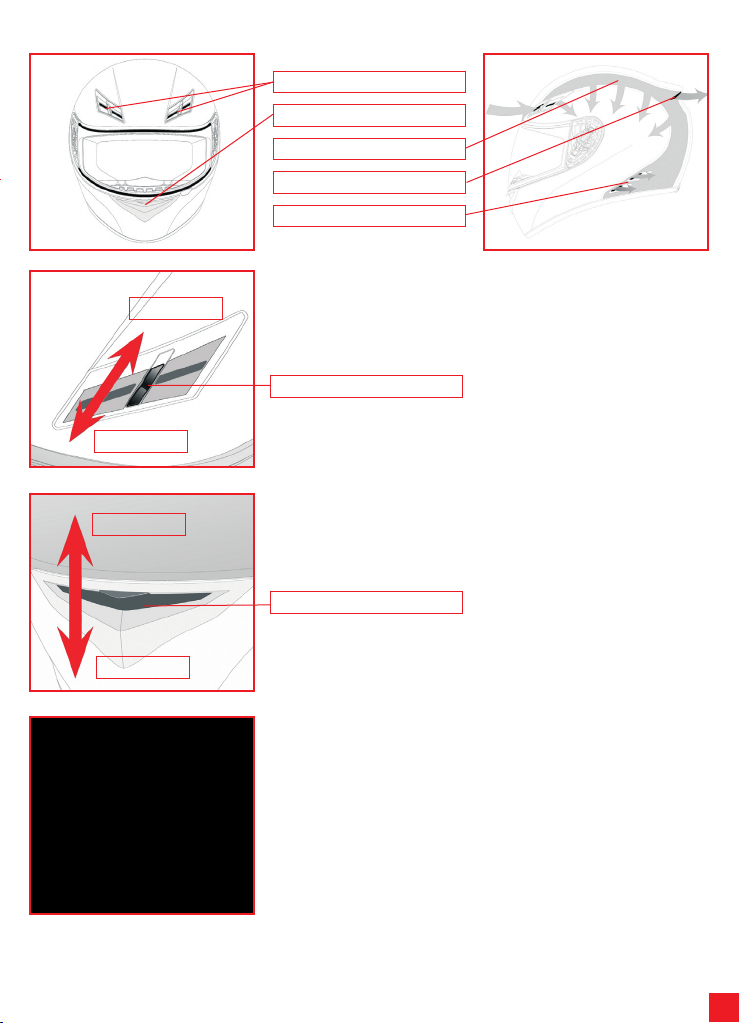
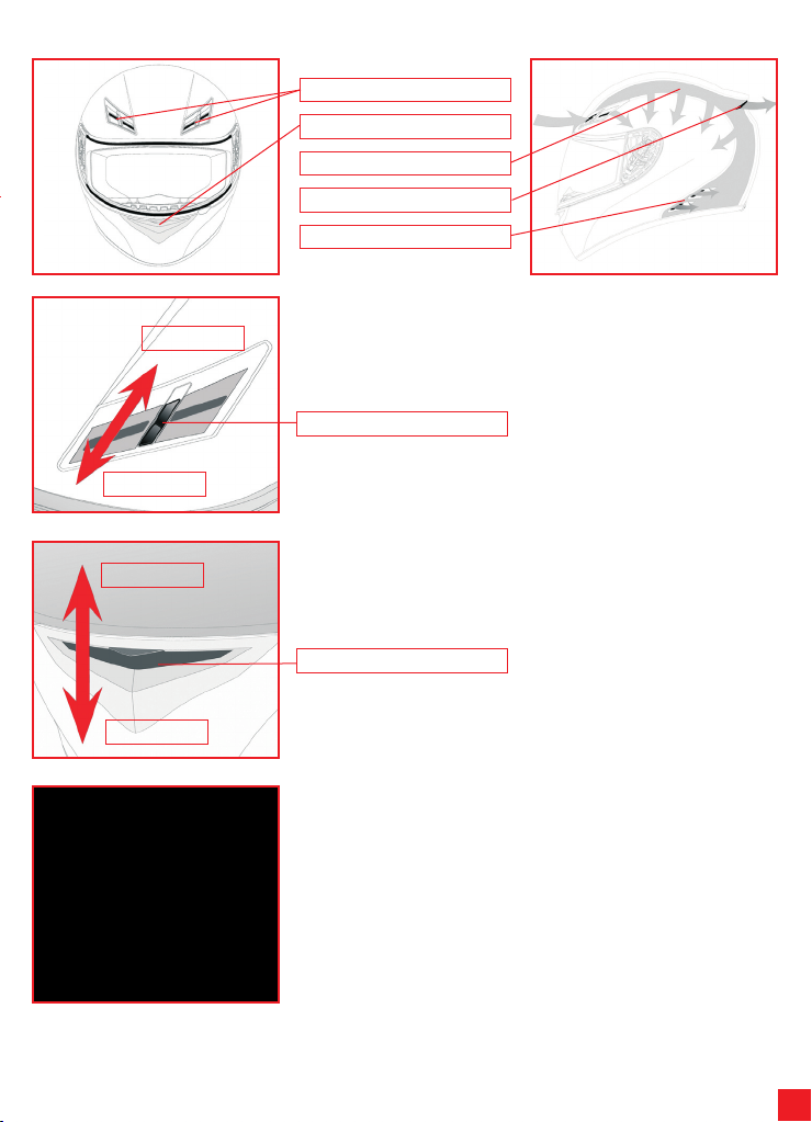
2) SISTEMA DI VENTILAZIONE
Aperto
Chiuso
Prese aria frontali
Presa aria muso
Canalizzazioni nel polistirolo
Presa aria top
Estrattori d’aria laterali
2.1) Apertura/chiusura prese aria superiori
Per aprire/chiudere le prese d’aria superiori, agire sul cursore fino a quando non si
sente lo scatto che indica il blocco del cursore in posizione.
Cursore
Chiuso
Aperto
2.2) Apertura/chiusura presa aria mentoniera
Per aprire/chiudere la presa aria mentoniera, abbassare/sollevare il meccanismo
della presa aria.
Meccanismo
2.3) Rimozione/Installazione Paranaso
Il paranaso può essere rimosso estraendolo con delicatezza dalla sua sede. Per
rimontarlo, inserire le bandelle in plastica nelle apposite sedi e verificare che sia ben
fisso.
Page 4
4
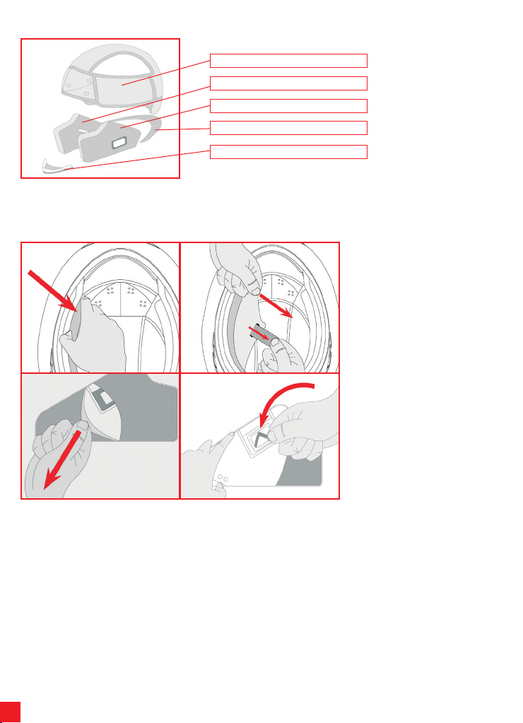
3) INTERNI
Cuffia
Guanciale destro
Guanciale sinistro
Paranuca
Protezioni anti-vento sotto gola
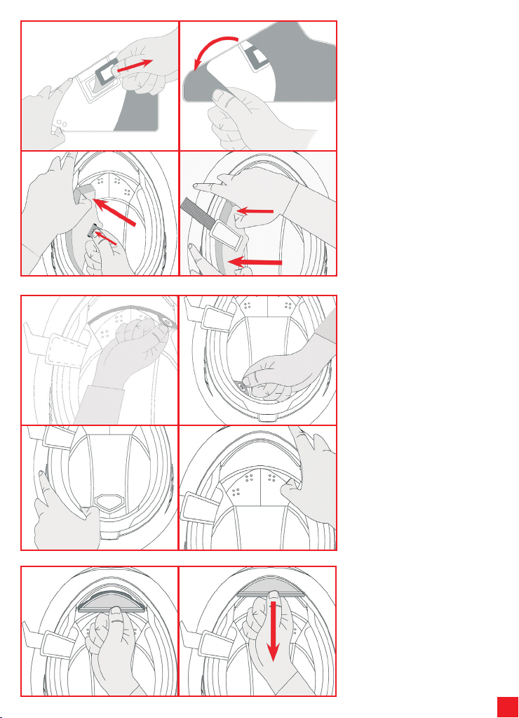
La cuffia, i guanciali destro e sinistro e la protezione anti-vento sono estraibili e lavabili. Per rimuovere e installare gli interni, fare
riferimento alle istruzioni e figure che seguono. Per lavare gli interni, fare riferimento al libretto “Safety Warning”.
1 2
3 4
3.1) R i mo z io ne / In s ta l la z io n e
guanciali
Per rimuovere i guanciali, impugnarli
ne lla p ar te ante riore v icino a lla
mentoniera del cas co e tira rli nella
direzione del la freccia (1). Sfi lare i
guanciali facendo passare il cinturino di
chiusura attraverso il foro ed estrarli (2).
Per rimuovere il rivestimento in tessuto,
procedere prima dalla parte posteriore
(3) e poi rimuovere l’anello di fissaggio
del passante sottogola ruotandolo (4).
Page 5
5
1 2
3 4
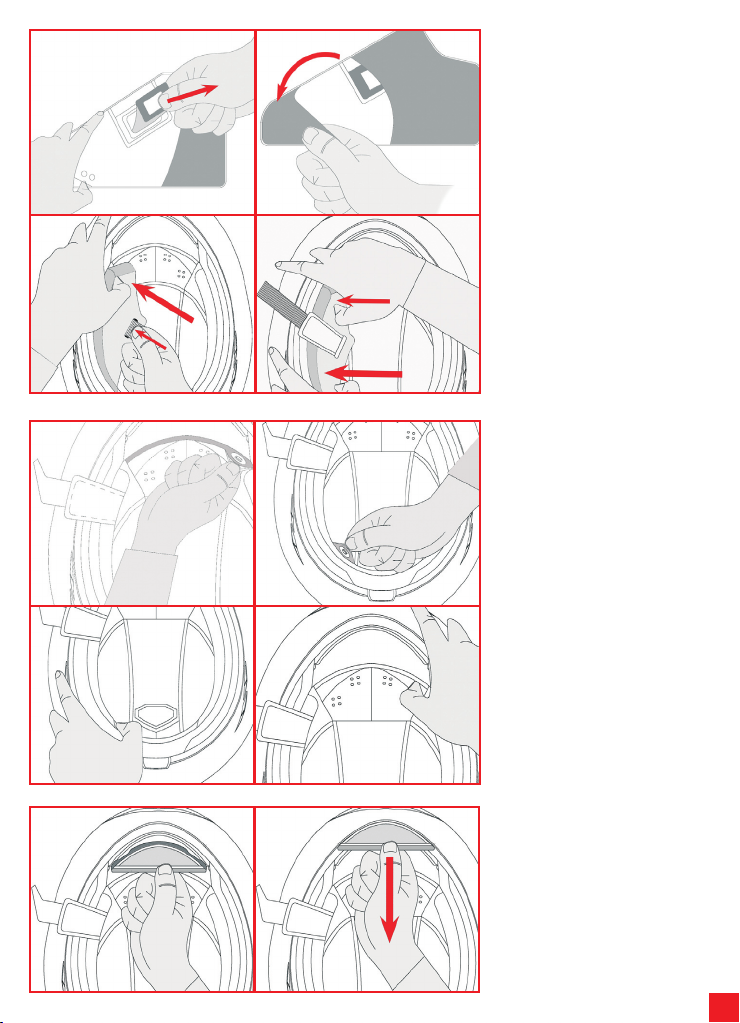
Per rimontare i guanciali, dopo aver
inserito l’anello rettangolare di fissaggio
(1) rivestire il guanciale con la copertura
in tessuto (2), accertandosi di accoppiare
corr ettamente guanc iale e rispettiva
copertura. Infilare i guanciali nel casco
introducendo il cinturino nell’apposito
foro di passaggio (3). Inserire il guanciale
prima nella parte poster iore e poi in
quel la anteriore (4). Verificare che i
guanciali siano perfettamente assicurati
al casco.
1 2
3 4
1 2
3.2) R i mo z io ne / In s ta l la z io n e
Cuffia
Per rimuovere la cuffia, sganciare i 2
bot toni auto matici post i n ella zona
anteriore (1) ed i 2 nella zona posteriore
del casco (2) e sfilarla dal casco.
NB Estrarre la cuffia solo DOPO avere
sganciato tutti i bottoni automatici di
fissaggio per evitare di danneggiare i
bottoni stessi e di scucire le parti in
tessuto.
Per rimontare la cuffia, inserirla all’interno
del casco e fissarla agganciando i 2
bottoni posterio ri (3) ed i 2 bo ttoni
anteriori (4)
3.3) I ns ta ll az io ne/ ri mo zi on e
protezione anti-vento sotto
gola
Per installare la protezione in tessuto,
inserire la bandella di plastica nello
spazio apposito sulla mentoniera. (1)
Per rimuover e la protezione, sfil arla
tirando nel senso della freccia. (2)
Page 6
6
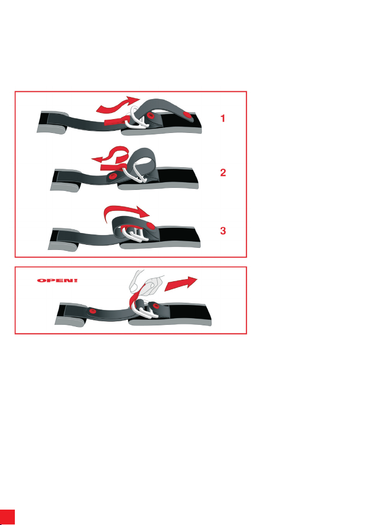
4) SISTEMA DI RITENZIONE
Ci sono tre tipi di sistemi di ritenzione:
- DD
- Fibbia a sgancio rapido
- Regolazione Micrometrica
Di seguito vengono riportate le indicazioni di utilizzo di tutte queste tipologie.
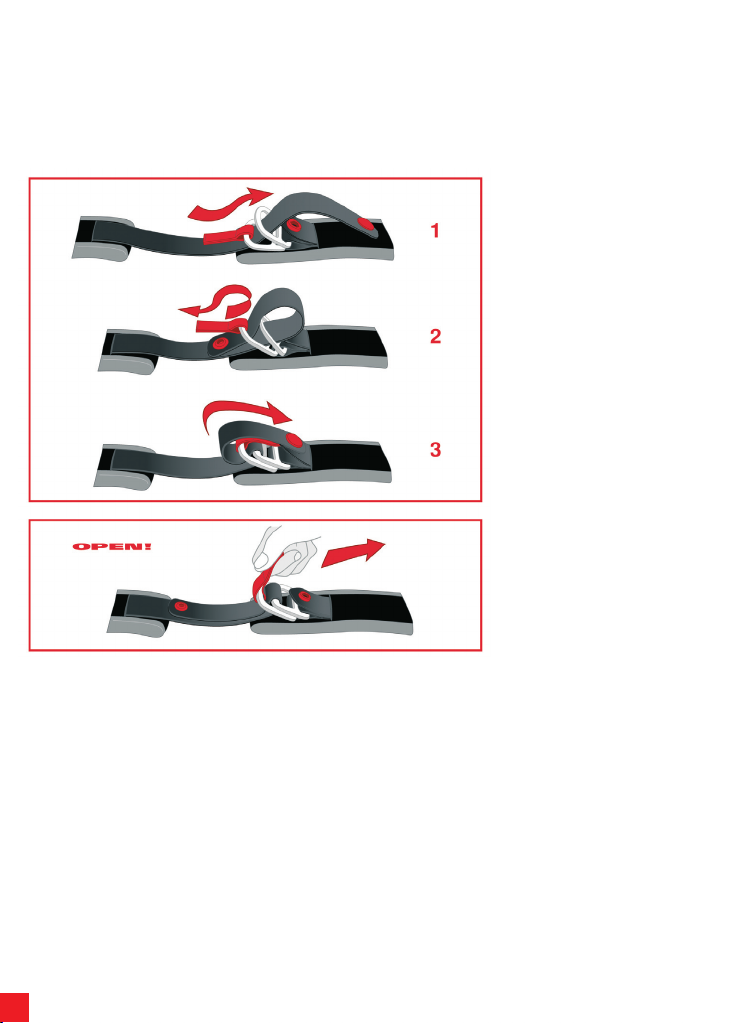
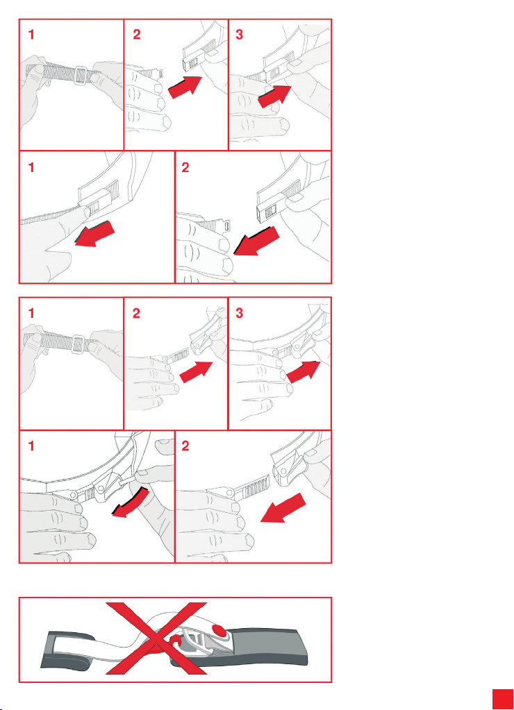
4.1) Sistema di ritenzione DD
Per allacciare il casco, passare il nastro
tra i due anelli (1), tirare la parte terminale
del nastro (2) fino a sentire il cinturino
pr eme re con tro la masce lla ed
agganciare il bottone automatico antisventolio (3), come indicato in figura.
Verificare che il casco rimanga ben saldo
in testa (vedere anch e il paragrafo
“Scelta del casco appropriato” del libretto
“Safety Warning”).
Per slac ciare il cas co, sga nciar e il
bottone automatico tirando il terminale
del nastro ed allentare il nastro sfilandolo
dagli anelli, aiutandosi con la linguetta
rossa, come indicato in figura.
Page 7
7
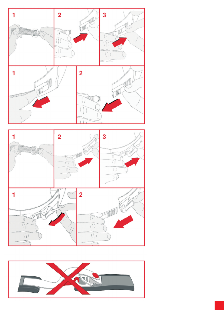
4.2) Si st em a di ritenzione con
fibbia a sgancio rapido
Il sistema di ritenzione con fibbia a
sg an cio ra pi do nec es sita d i un a
regolazione
al cinturino prima di essere allacciato.
Seguendo le indicazioni della figura che
segue, reg ol ar e la lung he zz a del
cinturino aumentando o riducendo la
porzione di nastro che passa attraverso
l’anello (1) fino ad ottenere una calzata
del casco adeguata quando il cinturino è
allacciato.
Per allacciare il casco, inserire la fibbia
nel meccanismo di ritenzione (2) fino a
sentire lo scatt o della chiusura (3).
Verificare che il casco rimanga ben saldo
in testa (vedere anch e il paragrafo
“Scelta del casco appropriato” del libretto
“Safety Warning”).
Per slacciare il casco, agire sul pulsante
rosso (1) per aprire il meccanismo di
ritenzione e poi sfilare la fibbia (2) come
indicato nella figura che segue.
4.3) Si st em a di ritenzione con
regolazione micrometricaIl
sistema di ritenzione con regolazione
mi crome tr ica nec essit a d i u na
regolazione al cinturino prima di essere
allacciato. Seguendo le indicazioni della
figura che segue, regolare la lunghezza
del cinturino aumentando o riducendo la
porzione di nastro che passa attraverso
l’anello metallico (1) fino ad ottenere una
calzata del casco adeguata quando il
cintur ino è allacciato. Per allacciare il
casco, inserire la linguetta dentata nella
fibbia metallica (2) e spingerla a fondo
(3) fino a sentire il cinturino premere
con tro la mascella . Il sistema con
regolazione micrometrica consente poi
un’ulteriore e più precisa “taratura” del
comfort e della vestibilità grazie alla
possibilità di usare il numero di scatti
della linguetta dentata che si preferisce
(e’ consigliabile comunque inserire la
lingue tta nella fib bia il più a fondo
possibile). Verificare che il casco rimanga
ben saldo in testa (vedere anche il
paragrafo “Scelta del casco appropriato”
del libretto “Safety Warning”).
Per slacciare il casco, sollevare la levetta
rossa aiutando si con la fettu ccia di
tessuto (1) e poi sfilare la fibbia (2) come
indicato in figura.
N.B. PULSANTI/VELCRO POSTI SUL
SI STE MA DI RIT ENZIO NE N ON
HANNO FUNZIONE DI FISSAGGIO MA
SOL O DI ANTI-S VENTOLIO: N ON
VANNO UTILIZZATI IN ALTERNATIVA
PER ALLACCIARE IL CINTURINO.
Page 8
8
English
1) VISOR
1 2
THIS HELMET’S SHELL IS MADE OF THERMOPLASTIC
THIS HELMET’S LINER IS MADE OF POLYSTIRENE (EPS)
1.1) Visor Mechanism
Upper connection housing
Visor stop 1
Visor stop 2
Movement base teeth
Visor stop cursor
1.2) Visor Removal/Installation
The visor is made of non-scratch polycarbon and has connections that fit into the
housings on the movement base. The teeth of the visor interact with the teeth on the
movement base to offer stability while the visor is open in the various positions.
Upper connection
Lower connection 1
Visor teeth
Lower connection 2
We recommend that you carry out the following operations while resting the
helmet on a flat surface.
To remove the visor, rotate it upwards
until it is completely open (1). Starting
from one of the two sides of the helmet,
pull the visor stop cursor down (2) and
extract the hook-up connections of the
visor. Repeat the operation on the other
side and remove the visor.
3 4
To install the visor, starting from one side
of the helmet, with the visor completely
raised, insert the upper connection of the
visor into its housing on the movement
base (3). Then insert lower connections
1 and 2 of the visor in the respective
visor stop devices (pulling the cursor
downwards if necessary) (4). Repeat the
operation on the other side. Lower the
visor and check that it works properly.
NB If the visor does not fit perfectly to
the profile of the edge of the helmet, it
might be necessary to adjust o r
replace the visor mechanism base. In
this case, contact an AGV service
centre.
Page 9
9
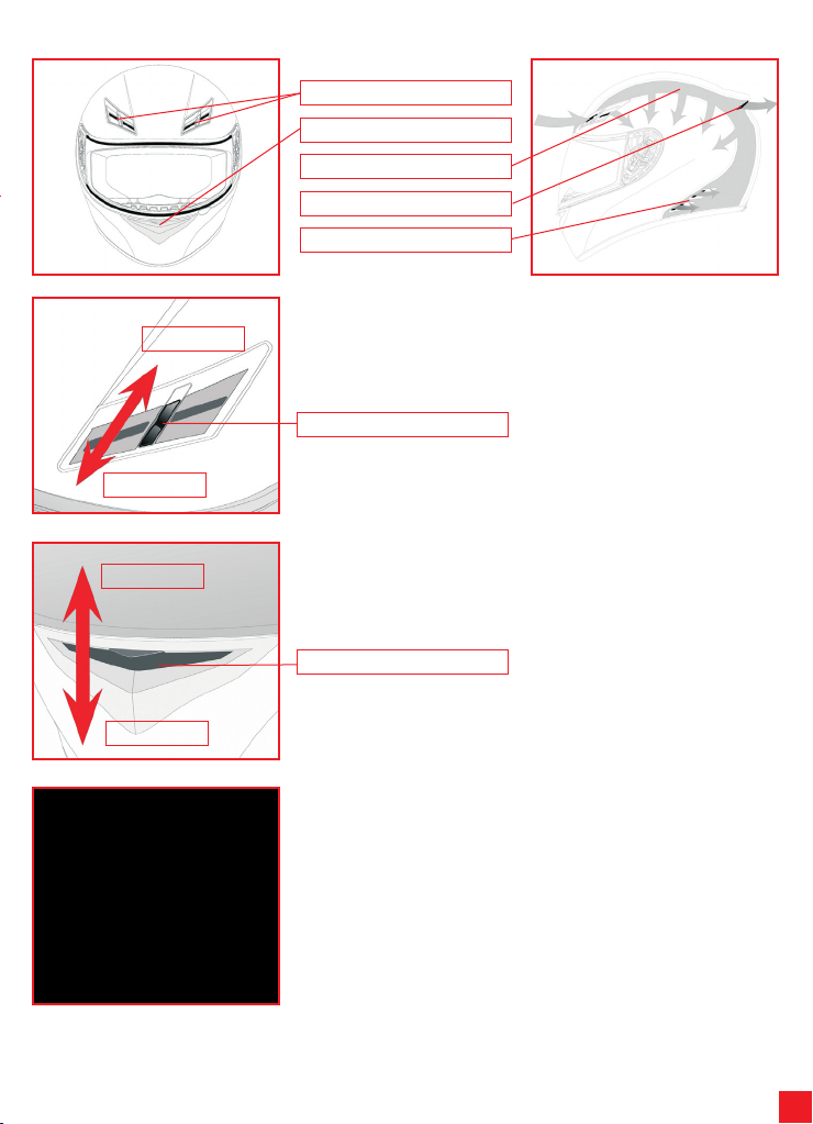
2) VENTILATION SYSTEM
Open
Closed
Front air inlets
Muzzle air inlet
Channels through polystyrene
Top air inlet
Side air extractors
2.1) Opening/closing upper air inlets
To open or close the upper air inlets, move the cursor until it clicks into position.
Cursor
Closed
Open
2.2) Opening/closing chin strap air inlets
To open or close the chin strap air inlets, raise or lower the air inlet mechanism.
Mechanism
2.3) Nose guard Removal/Installation
The nose guard can be removed, gently extracting it from its housing. To refit it, insert
the plastic bands into their housings and check that it is secure.
Page 10
10
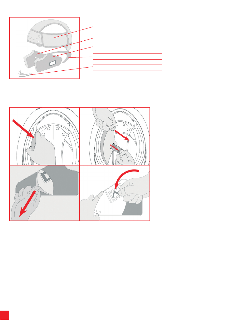
3) INNERS
Cap
Right cheek pad
Left cheek pad
Neck guard
Throat wind shield
The cap, right and left cheek pads and wind shield are removable and washable. To remove and install the inners, follow the
instructions and observe the figures below. To wash the inners, please see the “Safety Warning” booklet.
1 2
3 4
3.1) Cheek pad Removal/Installation
To remove the cheek pads, grip them at
the front near the helmet chin strap and
pull in the direction of the arrow (1).
Remove the cheek pads, passing the
closing strap through the holes and
extracting them (2). To remove the fabric
cover, proceed from the back (3) and
then remove the ring fastener of the
throat strap by twisting it (4).
Page 11
11
1 2
3 4
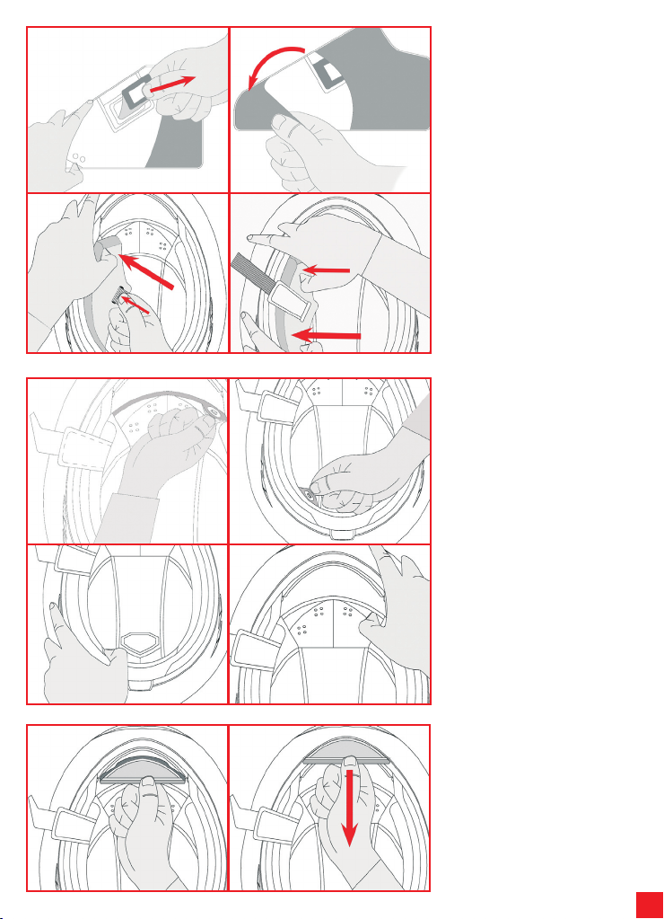
To refit the cheek pads, after inser ting
the rectangular ring fastening (1) cover
the cheek pad with its fabric cover (2)
ensuring that the cheek pad and its cover
are correctly coupled. Slide the cheek
pads into the helmet, slotting the strap
into the appropriate hole (3). Insert the
rear part of the cheek pad first followed
by the front part (4). Check that the
cheek pads are perfectly secured to the
helmet.
1 2
3 4
1 2
3.2) Cap Removal/Installation
To remove the cap, release the 2 press
studs at the front (1) and the 2 at the
back of the helmet (2) and slide them out
of the helmet.
NB Extract the cap only after releasing
all the press studs to avoid damaging
them and preven t damag e to the
fabric parts.
To refit the cap, insert it inside the helmet
and clip the 2 press-studs at the back (3)
and the 2 at the front (4) into place.
3.3) Throat wind shield removal/
installation
To install the fabric shield, inser t the
plastic band in the space in the chin
strap.
To remove the shield, slide it out, pulling
in the direction of the arrow.
Page 12
12
4) RETENTION SYSTEM
There are three types of retention system:
- DD
- Quick release buckle
- Micrometric adjustment buckle
The instructions for the use of all three types are given below.
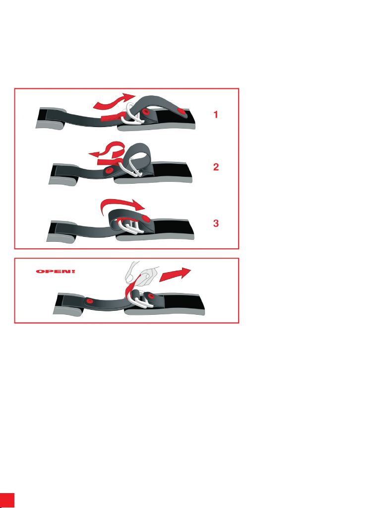
4.1) DD retention system
To fasten the helmet , slot the tape
through the two rings (1), pull the end of
the tape (2) until the strap pre sse s
against the jaw and click the anti-flapping
press-stud (3) into place as shown in the
figure. Check that the helmet fits snugly
(see the paragraph entitled “Choosing
the right helmet” in the “Safety Warning”
booklet).
To remove the helmet, release the pressstud by pulling the end of the tape and
loosen the tape, pulling it through the
rings, using the red tab as shown in the
figure.
Page 13
13
4.2) Quick release buckle retention
system
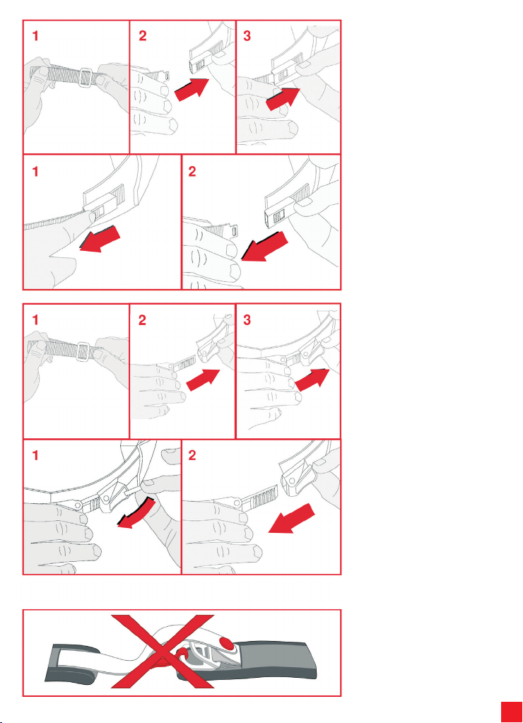
With the quick release buckle retention
system, the strap must be adjusted
before being fastened.
Following the indications of the figure
below, adjust the length of the strap,
lengthening or shortening the portion of
tape that passes through the metal ring
(1) until the helmet fits snugly when the
strap is fastened.
To fasten the helmet, slot the buckle into
the retention mechanism (2) until it clicks
closed (3).Check that the helmet fits
snugly (see th e p aragraph entitled
“Choosing the right helmet” in the “Safety
Warning” booklet).
To remove the helmet, use the red button
(1) to open the retention mechanism and
then open the buckle (2) as shown in the
figure below.
4.3) Micrometric adjustment buckle
retention
systemWith the micrometric adjustment
retention system, the strap must be
adjusted before being fastened.
Following the indications of the figure
below, adjust the length of the strap,
lengthening or shortening the portion of
tape that passes through the metal ring
(1) until the helmet fits snugly when the
strap is fastened.
To fasten the helmet, slot the serrated
tab into the metal buckle (2) and push it
as far as possible (3) until the strap
presses against the jaw. The micrometric
adjustment system enable further, more
precise “calibration” of comfort and fit
thanks to the possibili ty to use the
preferred number of positions on the
serrated tab (It is best to insert the tab as
far as possible into the buckle).
Check that the helmet fits snugly (see
the paragraph entitled “Choosing the
right helmet” in the “Safety Warning”
booklet).
To remove the helmet, lift the red lever
using the ribbon (1) and then open the
buckle (2) as shown in figure below.
N.B. BUTTONS/VELCRO POSITIONED
ON THE RETENTION SYSTEM ARE
NOT FASTENINGS BUT ARE ONLY TO
PREVENT FLAPPING: THEY MUST
NOT BE USED AS AN ALTERNATIVE
TO FASTENING THE STRAP.
Page 14
14
Français
1) ECRAN
1 2
3 4
THIS HELMET’S SHELL IS MADE OF THERMOPLASTIC
THIS HELMET’S LINER IS MADE OF POLYSTIRENE (EPS)
1.1) Mécanisme écran
Logement attache supérieure
Arrêt écran 1
Arrêt écran 2
Dents base mouvement
Glissière arrêt écran
1.2) Démontage/Remontage écran
L’écran est en polycarbonate anti-éraflures et est muni d’attaches qui sont introduites
dans les logements de la base mouvement. Les dents de l’écran interagissent avec
les dents de la base mouvement pour permettre d’obtenir une stabilité dans
l’ouverture de l’écran, dans les différentes positions.
Attache supérieure
Attache inférieure 1
Dents écran
Attache inférieure 2
Nous vous conseillons d’exécuter les opérations qui suivent en posant le
casque sur une surface plate.
Pour démonter l’écran, le relever jusqu’à
son ouverture totale (1). En partant d’un
des deux côtés du casque, tirer vers le
bas le curseur de l’arrêt écran (2) et
extraire les attaches d’accrochage de
l’écran. Répéter l’opération également
de l’autre côté et enlever l’écran.
Pour monter l’écran, en partant d’un côté
du casque, avec l’écran complètement
relevé, introduire l’attache supérieure de
l’écran dans son logement de la base
mo uv eme nt ( 3). Suc cessi ve ment,
introduire les attaches inférieures 1 et 2
de l’écran dans les arr êts écran
re sp ectiv emen t ( éve n tuell em ent
aiu tando si en tirant vers le bas le
cu rs eur) (4) . R épéte r l’ opéra tio n
également de l’autre côté. Abaisser
l’écran et en vérifier le fonctionnement
correct
NB Dans le cas où l’écran n’adhère
pas parfaitement au profil du bord du
casque, un réglage ou remplacement
de la base mécanisme écran pourrait
être nécessaire. Dans ce cas contacter
un point d’assistance AGV.
Page 15
15
2) SYSTÈME DE VENTILATION
Ouvert
Fermé
Prises d’air face
Prise d’air nez
Canalisations dans le polystyrène
Prise d’air top
Extracteurs d’air latéraux
2.1) Ouverture/fermeture aérateurs supérieurs
Pour ouvrir/fermer les aérateurs supérieurs, agir sur la glissière jusqu’à entendre un
déclic qui indique le bloc de la glissière en position.
Curseur
Fermé
Ouvert
2.2) Ouverture/fermeture aérateur mentonnière
Pour ouvrir/fermer l’aérateur de la mentonnière, abaisser/soulever le mécanisme de
l’aérateur
Mécanisme
2.3) Démontage/Montage Protège-nez
Le protège-nez peut être démonté en l’extrayant délicatement de son logement. Pour
le remonter, introduire les bandes en plastique dans les logements spécialement
prévus et vérifier qu’il soit bien fixé.
Page 16

16
3) PARTIES INTERNES
Coiffe
Coussin de joue droit
Coussin de joue gauche
Tour de cou
Protections anti-vent jugulaire
La coiffes, les coussins de joue droite et gauche et la bavette anti-remous peuvent être démontés et lavés facilement. Pour démonter
et remonter la partie interne, lire les instructions et consulter les figures suivantes. Pour laver la partie interne, consulter la notice
“Safety Warning”.
1 2
3 4
3.1) Démontage/Remontage des
coussins de joue
Pour enlever les coussins de joue, saisir
la partie avant à côté de la mentonnière
du casque et tirer dans la direction de la
flèche (1). Enlever les coussins de joue en
faisant passer la sangle de fermeture à
travers le trou et les enlever (2). Pour
enlever le revêtement en tissus, procéder
en premier par l’ arrière (3) et puis enlever
l’anneau de fixation du passant de la
mentonnière en le faisant tourner (4).
Page 17
17
1 2
3 4
Pour remonter les coussins de joue,
ap rè s a voir in tr o d u it l ’anneau
rectangulaire de fixation (1) revêtir les
coussins de joue avec la couverture en
tis su s (2) , en vérifiant de c oupler
corr ectem ent co us sin d e j ou e et
couver ture re spec tive . En fi ler les
coussins de joue dans le casque en
introduisant le sangle dans le trou de
pa ss age spéc iale ment p révu (3) .
Introdui re les coussins d e j oue en
premier dans la partie arrière et puis
dans celle avant (4). Vérifier que les
coussins de joue sont parfaitement fixés
au casque.
1 2
3 4
1 2
3.2) Démontage/Remontage Coiffe
Pour enlever la coiffe, décrocher les 2
boutons-pressions placés dans la zone
avant (1) et les 2 dans la zone arrière du
casque (2) et le dégager du casque.
NB Extrair e la coi ffe uniquement
APRÈS avoir décroché tou s les
boutons-pressions de fixation pour
éviter d’endommager les boutons et
de découdre les parties en tissus.
Pour rem onter la coi ffe, l’ insér er à
l’intéri eur du casqu e et le fixer en
accrochant les 2 boutons arrière (3) et
les 2 boutons avant (4)
3.3) Montage /démontage bavette
anti-remous jugulaire
Pour monter la bavette en tissus, insérer
sur la bande de plastique dans l’espace
prévu sur la mentonnière.
Pour démonter la protection, l’extraire en
tirant dans le sens de la flèche.
Page 18
18
4) SYSTEME D’ATTACHE
Il y a trois sortes de systèmes d’attache:
- 2D
-Boucle à retrait rapide
-Réglage Micrométrique
Ci-dessous, vous trouverez les indications pour les utiliser toutes.
4.1) Système d’attache 2D
Pour attacher le casque, passer la sangle
entre les deux anneaux (1), tirer le bout
de la sangle (2 ) ju squ’à ce que la
jugulaire appuie contre la mâchoire et
attacher le bouton automatique pour
l’empêcher de battre avec le vent (3),
comme indiqué sur la figure.
Vérifier que le casque reste bien en
place sur la tête (voir aussi le paragraphe
“Choix d’un casque approprie” du livret
“Safety Warning”).
Pour détacher le casque, décrocher le
bouton automatique en tirant sur le bout
de la jugulaire et agrandir la sangle en la
retirant des anneaux et en s’aidant de la
languette rouge, comme indiqué sur la
figure.
Page 19
19
4.2) Système d’attache avec boucle
à retrait rapide
Le système d’attache avec boucle à
retrait rapide a besoin d’un réglage de la
jugulaire avant d’être attaché.
En suivant les indications de la figure
suivante, régle r la lon gu eu r de la
jugulaire en augmentant ou en réduisant
la partie de sangle qui pass e dan s
l’anneau métallique (1) jusqu’à ce que
vous sentiez que le casque vous tient
bien la tête une fois la j ug ulaire
attachée.
Pour attacher le cas que, insér er la
boucle du mécanisme d’atta che (2)
jusqu’à ce que vous entendiez le déclic
de fermeture (3).
Vérifier que le casque reste bien en
place sur la tête (voir aussi le paragraphe
“Choix d’un casque approprie” du livret
“Safety Warning”).
Pour détacher le casque, utiliser le
bouton rouge (1) pour ouvrir le système
d’attache, puis re tirer la boucle (2)
comme indiqué sur la figure suivante.
4.3) Systè me d’atta che avec
réglage micrométrique
Le système d’a ttache avec régla ge
micrométrique a besoin d’un réglage de
la jugulaire avant d’être attaché.
En suivant les indications de la figure
suivante, régle r la lon gu eu r de la
jugulaire en augmentant ou en réduisant
la partie de sangle qui pass e dan s
l’anneau métallique (1) jusqu’à ce que
vous sentiez que le casque vous tient
bien la tête une fois la jugulaire attachée.
Pour attacher le cas que, insér er la
languette crantée dans la boucle en
métal (2) et la pousser à fond (3) jusqu’à
ce que vous sentiez la jugulaire appuyer
contre la mâchoire. Le système avec
réglage micrométrique permet par la
suite un autre “réglage” plus précis du
confor t et de l’aisance, grâce à la
possibilité d’utiliser le nombre préféré de
crans de la languette crantée (Nous vous
conseillons tout de même d’insérer la
lan guette la pl us po ssibl e dans la
boucle). Vérifier que le casque reste bien
en plac e sur la tête (voir auss i l e
pa ragra phe “Cho ix d’ un cas que
approprie” du livret “Safety Warning”)
Pour détacher le casque, soulever le
levier rouge en s’aidant du morceau de
tissu (1) puis décrocher la boucle (2),
comme indiqué sur la figure.
NB LES BOUTONS/VELCRO PLACES
SUR LE SYSTEME D’ATTACHE NE
SERVENT PAS A FIXER LA JUGULAIRE
MAIS SEULEMENT A L’EMPECHER DE
BATTRE AVEC LE VENT : ILS NE
DOIVENT PAS ETRE UTILISES COMME
SYS TE ME D’ATTACHE POUR LA
JUGULAIRE.
Page 20
20
Deutsch
1) VISIER
1 2
3 4
THIS HELMET’S SHELL IS MADE OF THERMOPLASTIC
THIS HELMET’S LINER IS MADE OF POLYSTIRENE (EPS)
1.1) Visiermechanik
Oberer Eingriffsitz
Visierhalter 1
Visierhalter 2
Zähne für Grundbewegung
Schieber Visierblockierung
1.2) Entfernung/Montage des Visiers
Das Visier ist aus kratzfestem Polycarbonat und ist mit Eingriffen ausgestattet, die sich
in die Sitze der Grundbewegung einhaken. Die Zähne des Visiers greifen in die Zähne
der Grundbewegung ein, um eine Stabilität bei der Visieröffnung in verschiedenen
Positionen zu gewährleisten.
Obiger Eingriff
Unterer Eingriff 1
Visierzähne
Unterer Eingriff 2
Während diesem Vorgang empfehlen wir, den Helm auf eine flache Ebene zu
legen.
Um das Visier abzunehmen, muss es
vollständig geöffnet werden (1). An eine
der beiden Seiten des He lm s den
Schieber der Visierblocki erung nach
u n te n z i eh en ( 2) u nd d ie
Ver bin dun gse ing rif fe d es V isi ers
herausziehen. Diesen Vorgang auch auf
der anderen Helmseite wiederholen und
das Visier entfernen.
Für die Mo ntage , bei voll ständ ig
hochgeh obe nes Visier, an eine r der
beiden Helmseiten den oberen Eingriff
des V is iers in d en Si tz d e r
Grundbewegung einstecken (3). Danach
die unteren Eingriffe 1 und 2 des Visiers
in die entsprechenden Visierblockierungen
einrasten (eventuell kann man sich durch
Herunterziehen des Schiebers helfen)
(4). Den gleichen Vorgang auch auf der
anderen Seite wiederholen. Das Visier
herunterklappen und die gute Funktion
überprüfen.
NB Sollte das Visier nicht perfekt an
dem Profil des Helmrandes haften, ist
wahrscheinlich eine Regulierung oder
Auswechseln der Mechanismusbasis
des Visiers notwendig. In diesem Fall
wend en Si e sic h an ein e AG VKundendienststelle.
Page 21
21
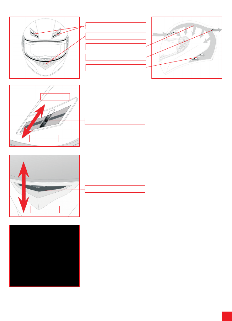
2) LÜFTUNGSSYSTEM
Geöffnet
Geschlossen
Vordere Lufteinnahme
Nasen-Mund-Lufteinnahme
Kanalisierungen im Polystyrol
Top-Luftinnahme
Seitliche Luftabzieher
2.1) Öffnung/Schließung der oberen Luftzufuhr
Um die oberen Luftzuführer zu öffnen/schließen, muss der Schieber betätigt werden,
bis man das Einschnappen hört, das darauf hinweist, dass der Schieber in der
Position blockiert ist.
Schieber
Geschlossen
Geöffnet
2.2) Öffnung/Schließung der Kinnluftzufuhr
Um die Kinnluftzufuhr zu öffnen/schließen, muss die Mechanik der Luftzufuhr
gesenkt/gehoben werden
Mechanik
2.3) Entfernung/Montage des Nasenschutzes
Der Nasenschutz muss entfernt werden, indem man ihn vorsichtig aus seinem Sitz
zieht. Um ihn wieder einzusetzen, die Plastikzähnchen in die Eingriffe einhaken und
überprüfen, dass er fest in seinem Sitz sitzt.
Page 22
22
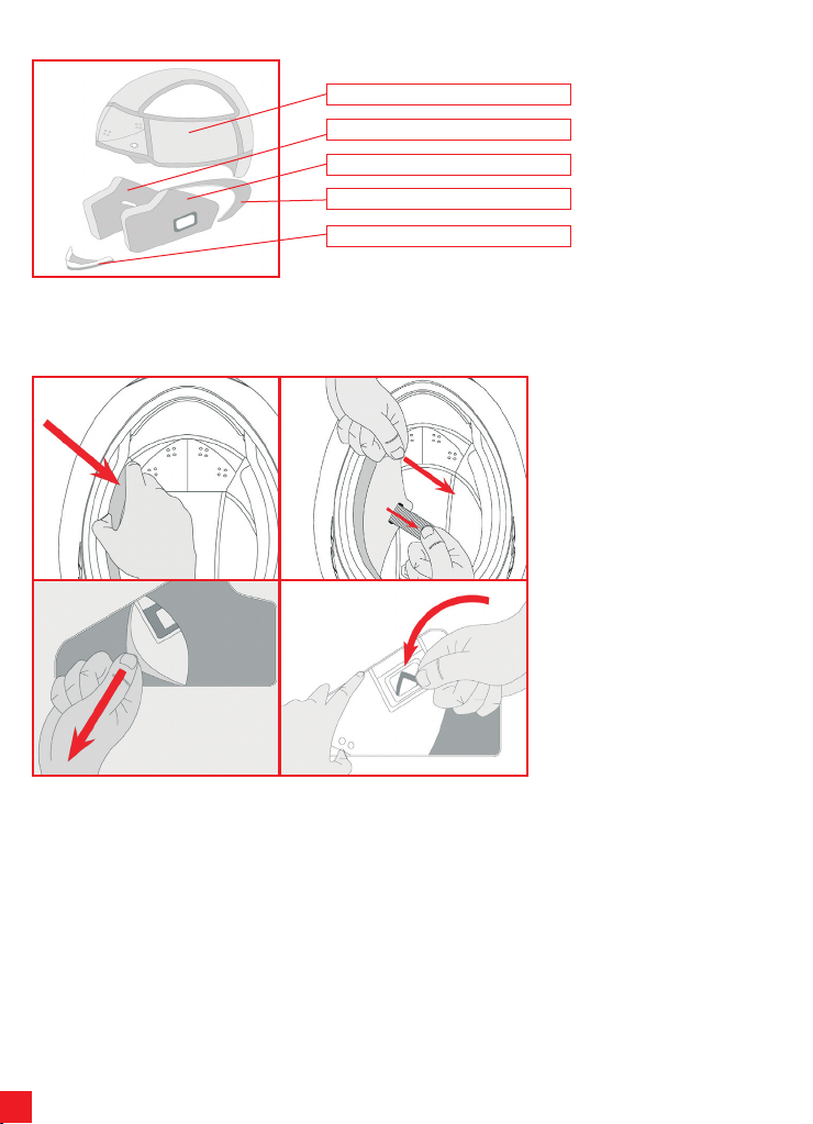
3) INNENTEILE
Haube
Rechter Wangenschutz
Linker Wangenschutz
Genickschutz
Windschutz unter dem Hals
Die Haube, der rechte und linke Wangenschutz, der Genickschutz und der Windschutz können entfernt und gewaschen werden.
Für die Entfernung und Einbau der Innenteile, verweisen wir auf die darauf folgenden Hinweise und Abbildungen. Für das Waschen
der Innenteile verweisen wir auf das Heftchen “Safety Warning”.
1 2
3 4
3.1) Entfe rnu ng/ Mon tag e des
Wangenschutzes
Für die Entfernung der Wangenschutzen,
diese mit der vorderen Seite, in der Nähe
des Kinns, in Richtung des Pfeils ziehen
(1). Die Wangenschutze durch das Loch
des Verschlussriemens herausziehen
(2). Die Stoffverkleidung zuerst von der
hinteren Seite abnehmen (3) und dann
den Befestigungsring unter dem Hals
durch Drehen entfernen. (4).
Page 23
23
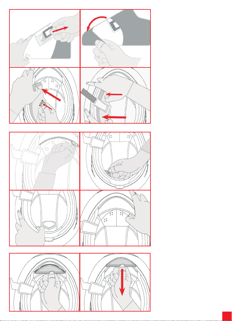
1 2
3 4
Für die Montage der Wangenschutze,
den rechteck ig en B efestig ungsring
einste cken (1) und die Stoffe inlage
wieder in den Wangenschutz einlegen
(2), indem beachtet werden muss, dass
die Ei nl a ge pe rfek t au f dem
Wangenschutz sitzt. Den Wangenschutze
in den Helm eins etzen , inde m d er
Riemen durch das entsprechende Loch
gezogen wird (3). Den Wangenschutz
zuerst in der hinteren Seite, dann in der
vorderen Seite einlegen (4). Sicherstellen,
dass die Wangenschutze perfekt im
Helm sitzen.
1 2
3 4
1 2
3.2) Entfernu ng/Mon tage d e r
Haube
Für die Entfernung der Haube, die beiden
Druckknöpfe an der vorderen Seite (1)
und die beiden an der hinteren Seite des
Helms (2) lösen und sie aus dem Helm
ziehen.
NB Die Haube erst NACH Öffnen aller
B e f es t i g u n g s d r u c k kn ö p f e
herausziehen, um eine Beschädigung
der Druckk nö pfe sel bst und e in
Auftre nnen d er Geweb et eile zu
vermeiden.
Um die Haube wieder einzubauen, diese
in den Helm legen und die 2 hinteren (3)
und d ie 2 vord er en Dr uckk nöpfe
einrasten (4).
3.3) Monta ge/E ntf ern ung d e s
Wi nds chu tzes u nter d em
Hals
Für die Montage des Gewebeschutzes,
den Plastikstreifen in die entsprechende
Auss par ung au f de m Ki nnsch utz
einsetzen.
Zur Entfernung der Schutzvorrichtung,
diese durch Ziehen in Richtung des
Pfeils herausziehen.
Page 24
24
4)RÜCKHALTUNGSSYSTEM
Es gibt drei Typen von Rückhaltungssystemen:
- DD
- Schnalle mit rascher Auslösung
- Mikrometrische Regulierung
Folgend die Gebrauchsanweisungen der einzelnen Typologien:
4.1) Rückhaltungssystem DD
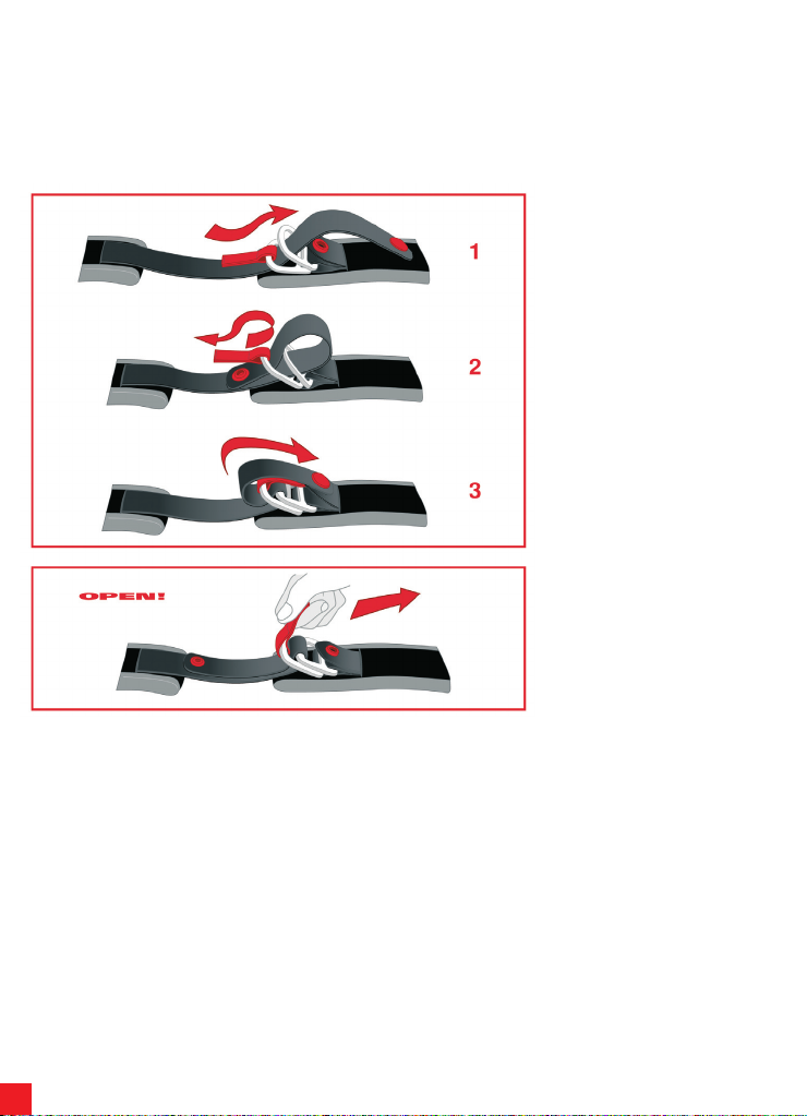
Zum Anschnallen des Helms, das Band
durch die zwei Ringe ziehen (1) und das
Ends tück des Ba nd es (2 ) sow eit
anziehen, bis der Riemen gegen das
Kinn drückt und den flattersic heren
Automatikknopf (3) schließen, wie in der
Abbildung dargestellt.
Überprüfen, dass der Helm fest auf den
Kopf sitzt (hierzu verweisen wir auf den
Para graph “Wahl eine s geeign eten
Helms” im Heft “Safety Warning”).
Zum Ö ff nen de s He lm s, d en
Aut omat ikkn opf d ur ch Zi eh en am
Bandend aufmachen und das Band aus
den beiden Ringen mit Hilfe der roten
Lasche ziehen, wie es in der Abbildung
dargestellt wird.
Page 25
25
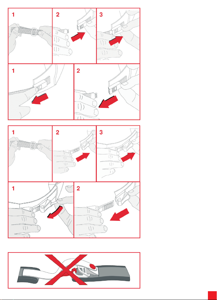
4.2) Rück h altun gss y stem m i t
rasch auslösbarer Schnalle
Bei dem Rückhaltungssystem mit rasch
auslösbarer Schnalle muss der Riemen
vor dem Anschnallen reguliert werden.
Nach den in der Abbildung dargestellten
Anweisungen die Riemenlänge durch
Kürzu ng bz w. Ver län ger ung de s
Bandstückes, das durch den Metallring
(1) gezogen wird regulieren, bis man ein
geeignet es Sit zen des Helms be i
angeschnalltem Riemen erreicht.
Für das Anschnallen des Helms, die
Schnalle in das Rückhaltungssystem bis
man das Einrasten hört, eindrücken (3).
Überprüfen, dass der Helm fest auf den
Kopf sitzt (hierzu verweisen wir auf den
Para graph “Wahl eine s geeign eten
Helms” im Heft “Safety Warning”).
Zum Abschnallen des Helms, den roten
Druck kn op f (1) betätigen, um das
Rückhaltungssystem zu öffnen und dann
die Schnalle herausziehen (2), wie es in
der Abbildung dargestellt wird.
4.3) Rück h altun gss y stem m i t
mikrometrischer
Regulierung Bei dem Rückhaltungssystem
mit rascher mikrometrischer Regulierung
muss der Riemen vor dem Anschnallen
reg uliert we rd en. Nach den i n der
Abbildung dargestellten Anweisungen
die Riemenlänge durch Kürzung bzw.
Verlängerung des Bandstückes, das
durch den Metallring (1) gezogen wird
reguli eren, bis man ei n geeigne tes
Sitzen des Helms bei angeschnalltem
Riemen erreicht. Zum Anschnallen des
Hel ms d ie Za hnlasc he in di e
Metallschnalle einführen (2) und sie tief
eind rücken (3), bis der Riemen fest
gegen da s Ki n n drückt. D a s
mikrometr ische Regulieru ngssystem
ermöglicht eine weitere und genauere
„E ic hung“ de s Kom fo r ts und der
Anpass un g d es Hel ms , Da nk der
Möglichkeit, die gewünschte Eingreifszahl
der Zahnlasche benutzen zu können. (Es
wird jedoch empfohlen, die Zahnlasche
so ti ef wie möglich in die Schnalle
einzudrücken). Überprüfen, dass der
Helm fest auf den Kopf sitzt (hierzu
verweisen wir auf den Paragraph “Wahl
eines geeigneten Helms” im Heft “Safety
Warning”).
Zum Abschnallen des Helms, die rote
Lasche mit Hilfe des Stoffbands nach
oben ziehen (1) und dann die Schnalle
herausziehen (2) wie es in der Abbildung
dargestellt wird.
N.B. DRUCKKNOPF/KLETTEN AUF
DE M R ÜCKHA LTU NGS SYSTEM
D IE N EN N IC H T F Ü R D I E
BEFESTIGUNG, SONDERN SIND NUR
GEGEN DAS FLATTERN. SIE DÜRFEN
NICHT ALS ALTERNATIVE FÜR DAS
AN SCH NAL LEN DE S R IEM ENS
BENUTZT WERDEN.
Page 26
26
Español
1) VISERA
1 2
3 4
THIS HELMET’S SHELL IS MADE OF THERMOPLASTIC
THIS HELMET’S LINER IS MADE OF POLYSTIRENE (EPS)
1.1) Mecanismo Visera
Posición inserto superior
Tope visera 1
Tope visera 2
Dientes base movimiento
Cursor tope visera
1.2) Remoción/Instalación Visera
La visera es de policarbonato irrayable y está dotada de insertos que van introducidos
en las sedes de la base movimiento. Los dientes de la visera se acoplan con los
dientes de la base del movimento para consentir la estabilidad de la visera una vez
abierta en las diferentes posiciones.
Inserto superior
Inserto inferior 1
Dientes de la visera
Inserto inferior 2
Recomendamos que execute as seguintes operações com o capacete
colocado numa superfície plana.
Para retirar la visera, girarla hacia arriba
hasta su total apertura (1). Partiendo de
uno de los dos lados del casco, tirar
hacia abajo el cursor del tope visera (2)
y extraer los insertos de enganche de la
visera. Repetir la operación también por
el otro lado y retirar la visera.
Para colocar la visera, par tiendo de un
la do de l ca sco , co n la v iser a
completamente levantada, introducir el
inserto superior de la visera en su sitio
de la b ase de m ovi mie nto (3 ).
Sucesivamente, introducir los insertos
inferiores 1 y 2 de la visera en los
re pectiv os topes de l a viser a
(eventualmente ayudarse tirando hacia
abajo el cursor) (4). Repetir la operación
también por el otro lado. Bajar la visera y
comprobar su buen funcionamiento.
NOTA. En caso de que la visera no se
adhiera perfectamente al perfil del
borde del casco, es posible que sea
necesaria una regulación o sustitución
de la base del mecanismo de la visera.
En tal caso dirigirse a un centro de
asistencia AGV.
Page 27
27
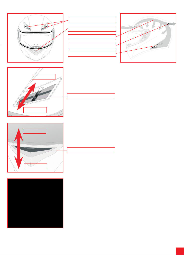
2) SISTEMA DE VENTILACIÓN
Abierto
Cerrado
Tomas de aire frontales
Toma de aire de la cara
Canalización del poliestireno
Toma de aire top
Extractores de aire laterales
2.1) Apertura/cierre tomas de aire superiores
Para abrir/cerrar las tomas de aire superiores, mover el cursor hasta que se escuche
el clic que indica el bloqueo del cursor en posición.
Cursor
Cerrado
Abierto
2.2) Apertura/cierre toma de aire en mentonera
Para abrir/cerrar la toma del aire en mentonera, bajar/levantar el mecanismo de la
toma de aire
Mecanismo
2.3) Remoción/Instalación Protege nariz
El protege nariz se puede retirar sacándolo delicadamente de su posición . Para
colocarlo de nuevo, introducir las bandas de plástico en su posición correspondiente
y comprobar que esté fijado bien.
Page 28
28
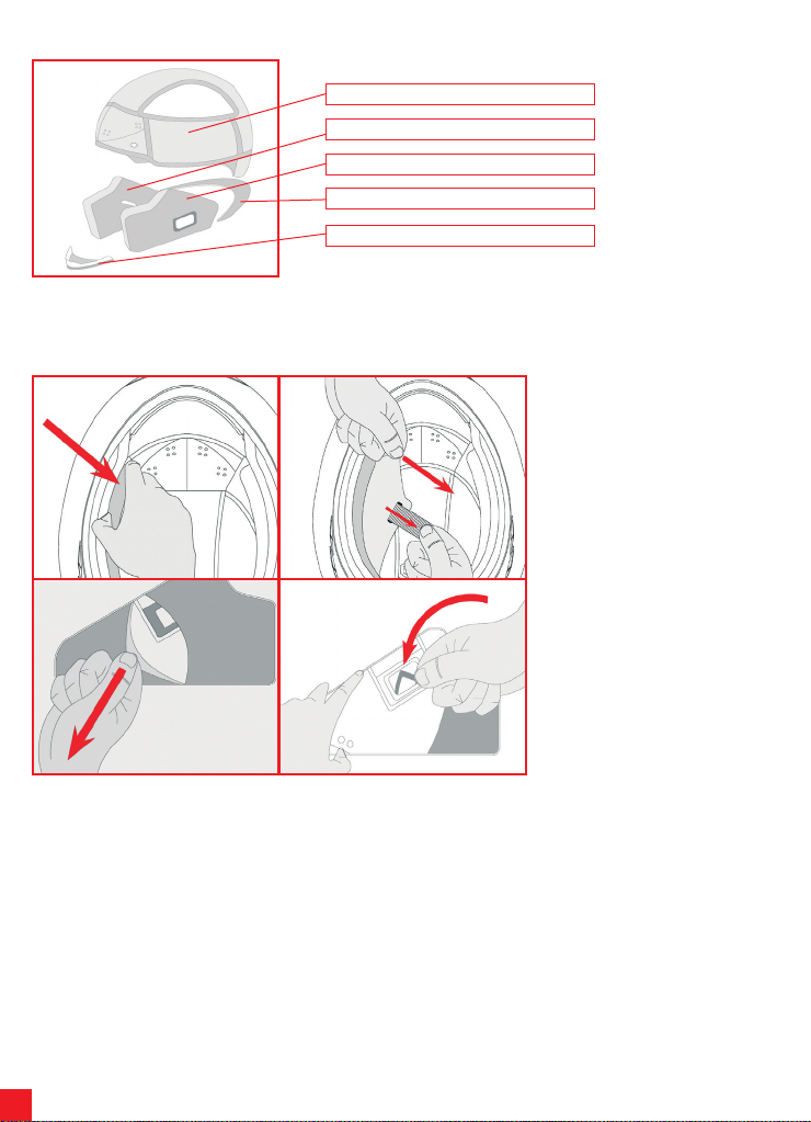
3) INTERIORES
Auriculares
Acolchado derecho
Acolchado izquierdo
Protege nuca
Protección anti-viento debajo de la garganta
Los auriculares, los acolchados derechos e izquierdos así como la protección anti-viento son extraíbles y lavables. Para extraer
y colocar los internos, seguir las instrucciones y las imágenes que siguen a continuación. Para lavar los internos, tener como
referencia el libro “Safety Warning”.
1 2
3 4
3.1) R e m o ci ón / I n s t al ac ió n
acolchado
Para retirar los acolchados, retirarlos por
la parte anterior que se encuentra más
cerca de la mentonera del casco y tirar
siguiendo la dirección de la flecha (1).
Retirar los acolchados pasando la cinta
del cierre por el orificio y sacarlas (2).
Para retirar el forro de tejido, proceder
primero por la parte posterior (3) y a
continuación retirar el anillo de fijación
de la trabilla de debajo de la garganta
girándolo (4).
Page 29
29
1 2
3 4
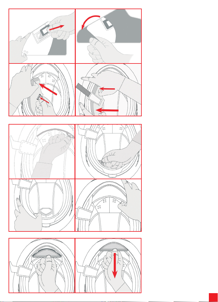
Para colocar de nuevo las almohadillas,
después de introducir el anillo rectangular
de fijación (1) recubrir las almohadillas
con el forro de tejido (2), asegurándose
de unir correctamente la almohadilla con
su r esp ect ivo for ro. C olo car las
almohadillas en el casco introduciendo
la cinta en su correspondiente orificio (3).
Introducir las almohadillas primero por la
parte posterior y seguidamente por la
an te rio r (4) . C ompro bar que las
almo ha dill as estén perfect am ente
acopladas al casco.
1 2
3 4
1 2
3.2) R e m o ci ón / I n s t al ac ió n
Auriculares
Para extraer los auriculares, desabrochar
los 2 botones a presión situados en la
zona anterior (1) y los 2 de la zona
posterior del casco (2) y sacarlos del
casco.
NOTA. Extraer los auriculares solo
DESPUÉS de haber desabrochado
tod os los bo to nes a pres ió n de
fijación para no dañar los botones y
no descoser las partes en tejido.
Para volver a colocar los auriculares,
introducirlos en el interior del casco y
fijarl os abr oc ha nd o los 2 b ot on es
po ste rio res (3) y lo s 2 bot one s
anteriores (4)
3.3) I n s t a la c ió n /r e mo c ió n
protección anti-viento debajo
de la garganta
Para instalar la protección de tejido,
introducir la solapa de plástico en el
es paci o corr espon dien te de l a
mentonera.
Para retirar la protección, hay que tirar
siguiendo la dirección de la flecha.
Page 30
30
4) SISTEMA DE SUJECIÓN
Hay tres tipos de sistemas de sujeción:
- DD
- Hebilla de desenganche rápido
- Regulación Micrométrica
A continuación se ilustran las indicaciones de uso de todas estas tipologías.
4.1) Sistema de sujeción DD
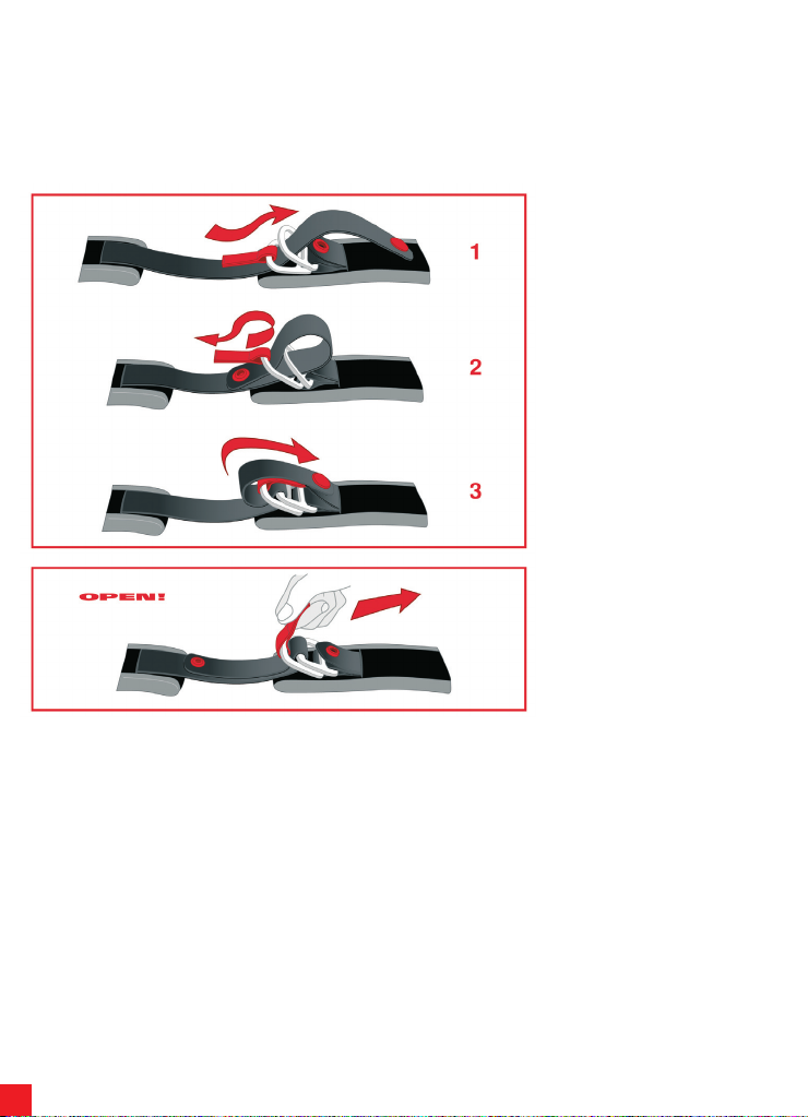
Para abrochar el casco, pasar la cinta
entre los dos anillos (1), tirar la parte
terminal de la cinta (2) hasta cuando la
correa apriete contra la mandíbula y
enganchar el botón automático antiondeo (3 ), según lo indicad o en la
figura.
Verificar que el casc o quede bien
colocado en la cabeza (ver también el
párrafo “Elección del casco idóneo” del
manual “Safety Warning”).
Pa ra d e sa br oc ha r el ca s co,
des enganch ar el botó n auto má tico
tirando el terminal de la cinta y soltar la
ci nta q uit ánd ola de l os an ill os,
ayudándose con la lengüeta roja, según
lo indicado en la figura.
Page 31
31
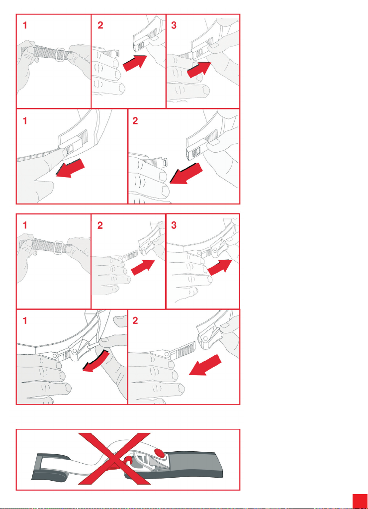
4.2) Siste ma d e sujeció n con
he bil la de dese nga nch e
rápido
El sistema de sujeción con hebilla de
desenganche ráp id o nece si ta una
regulación d e la cor re a an te s de
ab roc har se. C umpli endo con l as
indicaciones de la siguiente figura ,
re gu lar la lon gitud de l a cor rea
aumentando o disminuyendo el trozo de
cinta que pasa a través del anillo metálico
(1) hasta cuando el casco se coloque
adecuadamente cuando la correa esté
abrocha da. Para abrochar el casco,
colocar la hebilla en el mecanismo de
sujeción (2) hasta que se oiga el “click”
del cierre (3). Verificar que el casco
quede bien colocado en la cabeza (ver
también el párrafo “Elección del casco
idóneo” del manual “Safety Warning”).
Para desabrochar el casco, actuar en el
pulsador rojo (1) para abrir el mecanismo
de sujeción y luego quitar la hebilla (2)
según lo indicado en la figura
a continuación.
4.3) Siste ma d e sujeció n con
regulación micrométrica
El sistema de sujeción con regulación
micrométrica necesita una regulación de
la correa antes de abrocharse.
Cumpliendo con las indicaciones de la
siguiente figura , regular la longitud de la
correa aumentando o disminuyendo el
trozo de cinta que pasa a través del
anillo metálico (1) hasta cuando el casco
se coloque adecuadamente cuando la
correa esté abrochada.
Para abrochar el casco, introducir la
lengüeta dentada en la hebilla metálica
(2) y empujarla hasta el tope (3) hasta
cuando se advierta la presión de la
correa contra la mandíbula. El sistema
con regulación micrométrica permite
luego otra y más exacta “regulación” de
la comodidad y de la caída gracias a la
posibilidad de usar el número de “clikcks”
de la lengüeta dentada que se prefiera
(De todos modo es aconsejable introducir
la lengüeta en la hebilla lo más al tope
posible). Verificar que el casco quede
bien colocado en la cabeza (ver también
el párrafo “Elección del casco idóneo” del
manual “Safety Warning”).
Para desabrochar el casco, levantar la
palanca roja ayudándose con la cinta de
tejido (1) y luego quitar la hebilla (2)
según lo indicado en la figura.
NOTA : P ULSADORES /V ELCRO
POSICIONADOS EN EL SISTEMA DE
SUJECIÓN NO TIENEN FUNCIÓN DE
FIJACI ÓN SINO SÓLO DE ANT IONDEO: NO TIENEN QUE UTILIZARSE
C O MO A LTE R NAT I VA PAR A
ABROCHAR LA CORREA
Page 32
32
Portuguese
1) VISEIRA
1 2
3 4
THIS HELMET’S SHELL IS MADE OF THERMOPLASTIC
THIS HELMET’S LINER IS MADE OF POLYSTIRENE (EPS)
1.1) Mecanismo da Viseira
Compartimento de inserção superior
Bloqueio 1 da viseira
Bloqueio 2 da viseira
Dentes de base de movimento
Cursor de bloqueio da viseira
1.2) Remoção/Instalação da Viseira
A viseira é feita de policarbonato resistente a riscos e tem inserções que encaixam
nos compartimentos na base de movimento. Os dentes da viseira interagem com
os dentes da base de movimento para oferecer estabilidade enquanto a viseira é
aberta em várias posições.
Inserção superior
Inserção inferior 1
Dentes da viseira
Inserção inferior 2
Recomendamos que execute as seguintes operações com o capacete
colocado numa superfície plana.
Para remover a viseira, rode-a para cima
até ficar completamente aberta (1).
Comece de um dos lados do capacete,
empurre o cursor de bloqueio da viseira
para baixo (2) e retire as inserções da
viseira. Repita a operação do outro lado
e remova a viseira.
Para instalar a viseira, comece de um
dos lados do capacete, quando a viseira
estiver completamente levantada, insira
a inserção superior da viseira no seu
compartimento da base de movimento
(3). Em seguida, insira as inserções
inferiores 1 e 2 da viseira nos respectivos
disposit ivo s de bl oquei o da vise ira
(empurrando o cursor para baixo, se
necessário) (4). Repita a operação do
outro lado. Baixe a viseira e confirme que
se encontra a funcionar correctamente.
NB Se a v ise ira não e ncaix ar
perfeitamente no perfil da aresta do
cap acete, poderá ser necessário
ajustar ou sub st it ui r a base do
mecanismo da viseira. Nesse caso,
deve contactar um centro de serviço
da AGV.
Page 33
33
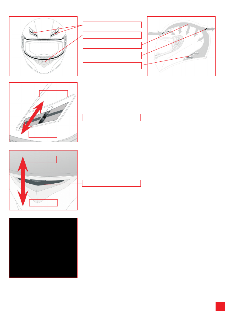
2) SISTEMA DE VENTILAÇÃO
Aberto
Fechado
Entradas de ar frontais
Entrada de ar do nariz
Canais através de poliestireno
Entrada de ar superiores
Extractores de ar laterais
2.1) Abertura/fecho de entradas de ar superiores
Para abrir ou fechar as entradas de ar superiores, movimente o cursor até ouvir um
clique que indica que se encontra na posição correcta.
Cursor
Fechado
Aberto
2.2) Abertura/fecho das entradas de ar da faixa do queixo
Para abrir ou fechar as entradas de ar da faixa do queixo, levante ou baixe o
mecanismo de entrada de ar.
Mecanismo
2.3) Remoção/Instalação de protecção do nariz
A protecção do nariz pode ser removida, retirando-o com cuidado do seu
compartimento. Para o reajustar, insira as bandas de plástico nos seus locais e
verifique se estão seguras.
Page 34
34
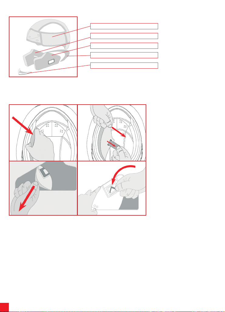
3) PARTES INTERIORES
Touca
Protector de face direito
Protector de face esquerdo
Protector do pescoço
Resguardo do vento para garganta
A touca, os protectores de face direito e esquerdo são removíveis e laváveis. Para remover e instalar as partes interiores, siga as
instruções e observe as figures abaixo. Para lavar as partes interiores, por favor consulte o folheto “Safety Warning”.
1 2
3 4
3.1) Remoçã o/In sta laçã o das
protecções de face
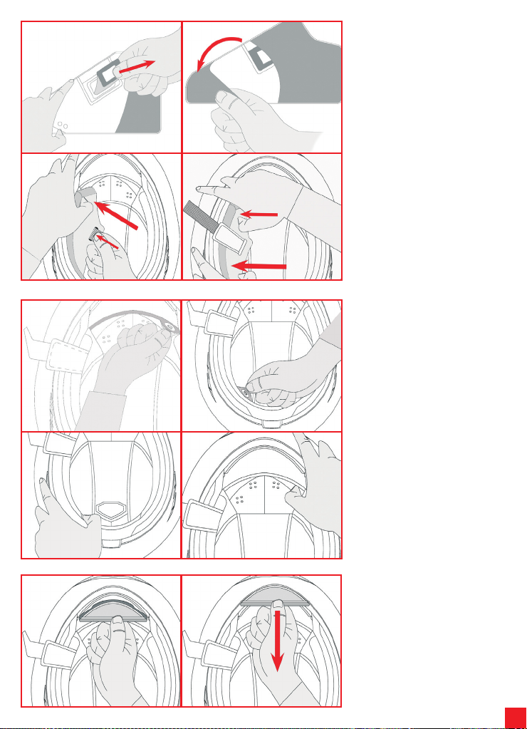
Para remover as protecções de face,
segure-as pela frente ao pé da faixa do
queixo do capacete e puxe na direcção
da seta (1). Remova as protecções de
face, passando a faixa de fecho através
dos orifícios e retire-as (2). Para remover
a capa de tecido, prossiga a partir da
parte de trás (3) e depois remova o
fixador da anilha da faixa da garganta,
girando-o (4).
Page 35
35
1 2
3 4
Para voltar a colocar as protecções da
face, após inserir o fixador da anilha
rectangular (1) cubra a protecção da
face com a sua capa de tecido (2)
certificando-se que a protecção de face
e a sua c apa es tão correctamente
acopladas. Faça deslizar as protecções
de face no capacete, encaixando a faixa
no orifício apropriado (3). Insira primeiro
a parte de trás do protector de face e, em
seguida, a parte frontal (4). Confirme se
as protecções da face estão devidamente
seguras ao capacete.
1 2
3 4
1 2
3.2) Remoção/Instalação de touca
Para remover a touca, liberte os 2 botões
na frente (1) e os 2 na parte de trás do
capacete (2) e faça deslizar para fora do
capacete.
NB Retire a touca apenas depois de
soltar os botões para evitar danificálos e prevenir danos nas partes de
tecido.
Para voltar a colocar a touca, insira-a
dentro do capacete e fixe os 2 botões na
parte de trás (3) e os 2 na parte da frente
(4) no devido lugar.
3.3) R e moç ã o/i n s ta l a çã o d e
resg uardo do vento par a
garganta
Para instalar o resguardo de tecido,
insira a banda de plástico no espaço da
faixa do queixo.
Para remover o resguardo, fa ça-o
deslizar para fora, puxando na direcção
da seta.
Page 36
36
4) SISTEMA DE RETENÇÃO
Existem três tipos de sistemas de retenção:
- DD
- Fivela a desengancho rápido
- Regulagem Micrométrica
A seguir são colocadas as indicações de utilização de todas estas tipologias.
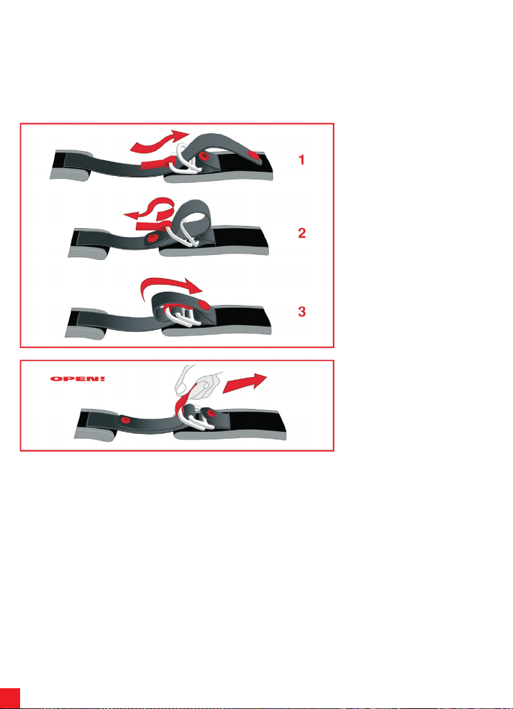
4.1) Sistema de retenção DD
Para fixar o capacete, passar a fita entre
os dois anéis (1), puxar a parte terminal
da fita (2) até ouvir a correia apertar
contra o queixo e enganchar o botão
automático (3), como indicado na figura.
Verificar se o capacete permaneceu bem
fixo na cabeça (ver também o parágrafo
“Escolha do capacete apropriado” do
manual “Safety Warning”).
Para retirar o capacete, desenganchar o
botão automático retirando o terminal da
fita, e soltar a fita retirando-a dos anéis,
auxiliando com a lingueta vermelha,
como indicado na figura.
Page 37
37
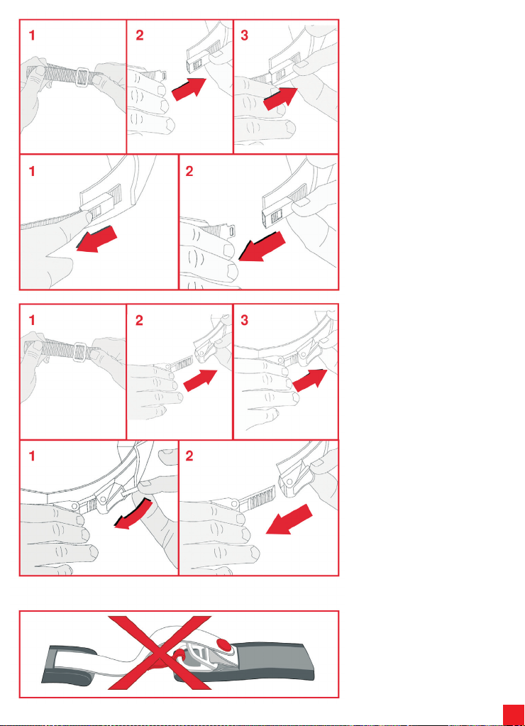
4.2) Sistema de retenção com fivela
de desengancho rápido
O sistema de retenção com fivela a
desengancho rápido necessita de uma
regulagem da correia ant es de ser
amarrado.
Seguindo as indicações da figura que se
segue, regular o comprimento da correia,
aumentando ou reduzindo a porção de
fita que passa através do anel metálico
(1), até obter a entrada do capacete
ad equa da qua ndo a c orre ia é
amarrada.
Para amarrar o capacete, inserir a fivela
no mecanismo de retenção (2) até sentir
o salto do fechamento (3). Fazer com
que o capacete permaneça bem fixo na
cabe ça (ver também o pa rá gr afo
“Escolha do capacete apropriado” do
manual “Safety Warning”).
Para desenganchar o capacete, actuar
no botão vermelho (1) para abrir o
mecanismo de retenção e depois retirar
a fivela (2) como indicado na figura que
se segue.
4.3) Sistem a de re tenção com
regulagem micromérica
O sistema de retenção com regulagem
mi cro mét rica ne ces sit a d e u ma
regulagem da correia ant es de ser
amarrado. Seguindo as indicações na
figura a seguir, regular o comprimento da
corr eia aumentando ou reduzindo a
porção da fita que passa através do anel
metá lico (1) até obter a entrada do
capacete adequada quando a correia
está amarrada. Para amarrar o capacete,
Inser ir a lingueta dentada na correia
metálica (2) e empurrá-la para o fundo
(3) até sentir a correia pressionar contra
a mandíbula. O sistema com regulagem
micrométrica permite um outro e mais
preciso “controle” do conforto e da
entrada graças à possibilidade de usar o
número de saltos da lingueta dentada
que se prefere (é acons elháve l de
qualquer maneira inserir a lingüeta na
correia o mais a fundo possível). Verificar
se o capacete permaneceu bem fixo na
cabe ça (ver também o pa rá gr afo
“Escolha do capacete apropriado” do
manual “Safety Warning”).
Para desamarrar o capacete, levantar a
alavanca vermelha, auxiliando com a fita
de tecido (1) e depois retirar a fivela (2)
como indicado na figura.
N.B. BOTÕES/VELCRO COLOCADOS
NO SISTEMA DE RETENÇÃO NÃO TÊM
FUNÇÃO DE FIXAÇÃO, MAS SOMENTE
PARA EVITAR QUE SE DESARRUMEM
COM O VENTO: NÃO DEVEM SER
UTILIZADOS COMO ALTERNATIVA
PARA AMARRAR A CORREIA
Page 38
38
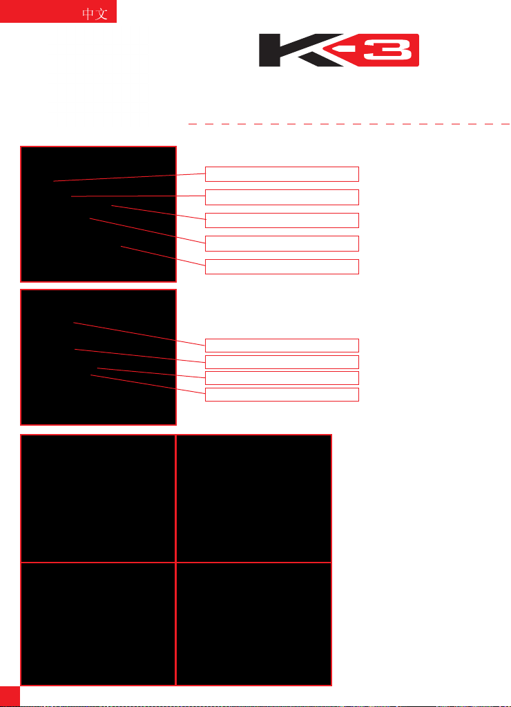
1) 帽舌
本头盔外壳采用热塑料制造
本头盔衬里采用聚苯乙烯(EPS)制造
1.1) 帽舌机制
上连接座
帽舌销1
帽舌销2
运动基齿
帽舌销游标
1.2) 帽舌的拆卸/安装
帽舌采用抗冲击性聚碳酸酯制造,其与运动基座相连接。帽舌齿与
运动基齿紧密啮合,使帽舌在不同位置上打开时都保持稳定。
上部连接
下部连接1
帽舌齿
下部连接2
我们建议你在进行如下操作时将头盔放在平坦表面上。
1 2
3 4
要拆卸下帽舌,将其旋转直至其完
全打开(1)。从头盔两面的任一面
开始,将帽舌销游标向下拉(2),
同时用力取出帽舌的连接钩。在另
一面重复进行,最后卸下帽舌。
要安装帽舌,从头盔两面的任一面
开始,将帽舌完全举起,将帽舌的
上部连接插入运动基座(3)。然后
将帽舌的下部连接1和2分别插入相
应的帽舌销装置(如需要时,将帽
舌向下拉)(4)。在另一面重复进
行。最后将帽舌放下来检查工作是
否正常。
注:如果帽舌不能与头盔的边缘轮
廓密切配合,可能需要调整或替换
帽舌基体。此时可与AGV服务中心
联系。
Page 39
39
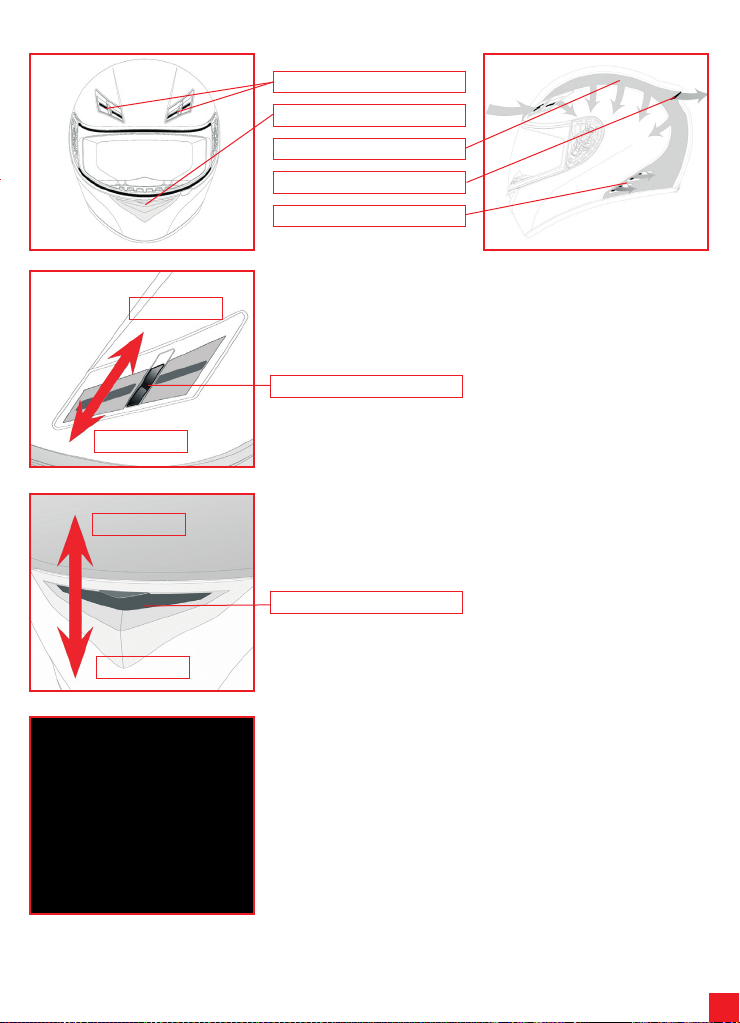
2) 透气系统
闭合
打开
前进气口
鼻进气口
透过聚苯乙烯的通道
顶进气口
侧透气口
2.1) 打开/闭合上进气口
要打开/闭合上进气口,可移动游标直至其发出“咔嚓”声表示到位。
游标
闭合
打开
2.2) 打开/闭合下巴皮带进气口
要打开或闭合下巴皮带进气口,可举起或放低进气机构。
机构
2.3) 护鼻的拆卸/安装
将护鼻从座子上轻轻往外取,即可拆卸护鼻。将塑料带插进座子便将其安装上,然
后检查是否牢靠。
Page 40
40
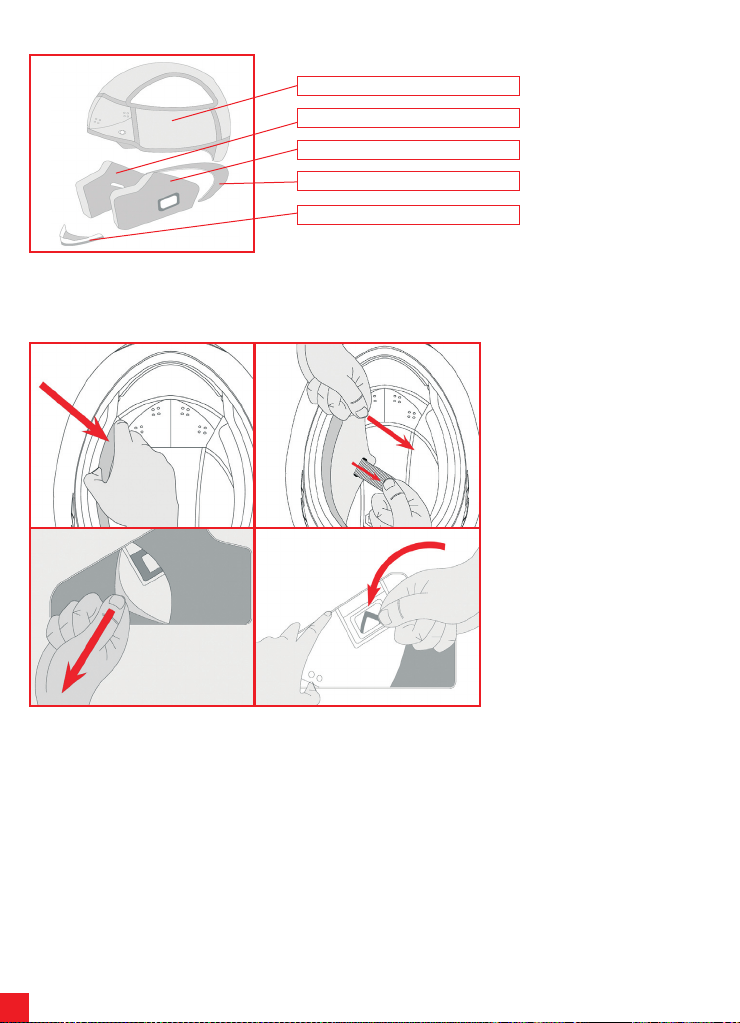
3) 内部部件
帽子
右颊垫
左颊垫
护颈
喉部风罩
帽子、左右颊垫和风罩都是可拆卸、可清洗的。要拆卸安装这些内部部件,请遵照下面指示,观察下面图例说明。
1 2
3 4
3.1) 颊垫的拆除/安装
要拆卸下颊垫,在靠近头盔下巴皮带
前端处抓住它们,向箭头所示方向拉
动(1)。移动颊垫,让它们通过孔穿
过闭合皮带并用力取出(2)。要拆卸
下纤维罩,从后向前进行(3),然后
扭转并拆开喉部皮带的环扣(4)。
Page 41
41
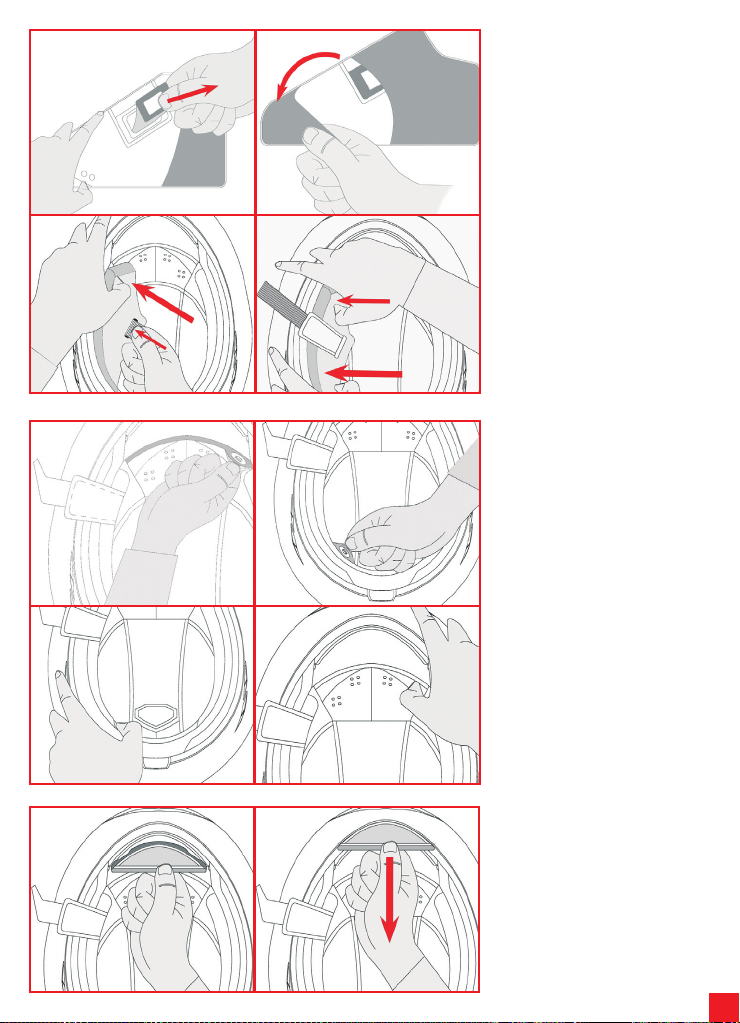
1 2
3 4
要装 上 颊 垫 , 在 插入长 方 环 扣 后 (
1),用纤维罩将颊垫罩上(2),确
保颊垫与纤维罩正确配合。将颊垫滑
进头盔,同时将皮带插入适当的孔(
3)。首先插入颊垫的后面部分然后再
插入前面部分(4)。检查颊垫是否完
全地装在头盔上。
1 2
3 4
1 2
3.2) 帽子的拆除/安装
要拆下帽子,松开头盔前面的2颗按扣
(1)及后面的2颗按扣(2),再将它
们滑动、从头盔中取出。
注:只能在松开所有按扣后才可取下
帽子,以避免损坏它们及纤维零件。
要装上帽子,将其插入头盔旁边,准
确地扣上后面2颗按扣(3)及前面2颗
按扣。
3.3) 喉部风罩的拆除/安装
要装上纤维罩,将塑料带插入下巴皮
带的空隙处。
要拆下纤维罩,将其滑出,向箭头所
示方向拉动。
Page 42
42
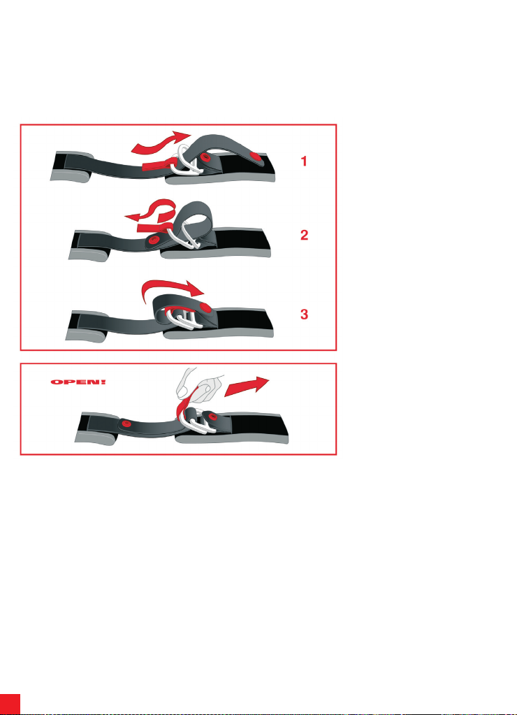
4) 束锁系统
有三种束锁系统:
- DD型
- 快速释放扣型
- 测微调整型
这三种类型的使用方法如下:
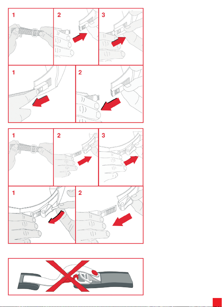
4.1) DD型束锁系统
要系紧头盔,应(1)使带子穿过两个
环,(2)拉带子的末端使带子紧压颚
部(3)将防摆动压条扣紧到位,如图
所示。
检查头盔是否佩戴舒适(请参预“安
全警 示 ” 小 册 子 中“选 择 正 确 的 头
盔”一段)。
要取下头盔,应拉带子的末端而使压
条松开,使带子松弛,使用红色小把
拉它让它穿出两个环,如图所示。
Page 43
43
4.2) 快速释放扣型束锁系统
对于快速释放扣型束锁系统,在紧固
之前必须先调整帽带。
请根据下图的说明进行:(1)调整帽
带的长度,加长或者缩短通过金属环
的带子部分直到带子系紧而头盔佩戴
舒适。
要系紧头盔,(2)使扣子穿进束锁系
统(3)直到完全扣紧。
检查头盔是否佩戴舒适(请参预“安
全警 示 ” 小 册 子 中“选 择 正 确 的 头
盔”一段)。
要取下头盔,应(1)使用红色按钮打
开束锁系统,(2)然后打开扣子,如
下图所示。
4.3) 测微调整型束锁系统
对于测微调整型束锁系统,在紧固之
前必须先调整帽带。
请根据下图的说明进行:(1)调整帽
带的长度,加长或者缩短通过金属环
的带子部分直到带子系紧而头盔佩戴
舒适。
要系紧头盔,(2)使带齿的小把穿进
金属扣(3)尽量用力推直到帽带压着
颚部。测微调整型束锁系统能更精确
地检测到舒适性,因为它使用了带齿
小把上合适数目的位置。(最好尽量
将小把插进扣子)。
检查头盔是否佩戴舒适(请参预“安
全警 示 ” 小 册 子 中“选 择 正 确 的 头
盔”一段)。
要取下头盔,应(1)使用小带子提起
红色推杆,(2)然后打开扣子,如图
所示。
注意:装在束锁系统上的按钮/ 维可
牢自粘带不是紧固件,而仅仅是用来
防止摆动。不能用它们作为固定帽带
的代用品。
Page 44
44
1) バイザー
THIS HELMET’S SHELL IS MADE OF THERMOPLASTIC
THIS HELMET’S LINER IS MADE OF POLYSTIRENE (EPS)
1.1) バイザーのしくみ
上部接続ハウジング
バイザー止め1
バイザー止め2
可動ベースの歯
バイザー止めカーソル 1
1.2) バイザーの取り外し/取り付け
バイザーは、ノンスクラッチポリカーボン製で、可動ベース上のハウジングに適合する接続
部があります。バイザーの歯は可動ベース上の歯と噛み合って、バイザーをさまざまな位置
まで開いて安定させることができます。
上部接続
下部接続 1
バイザーの歯
下部接続 2
ヘルメットを平らな面に置いて、以下の作業を行うことを推奨します。
1 2
3 4
バイザーを取り外すには、完全に開くまで
上に回転させます(1)。ヘルメットの片側か
らバイザー止めカーソルを引き下げ(2)、バ
イザーのフックアップ接続を引き出します。
反対側も同じようにしてバイザーを取り外
します。
バイザーを取り付けるには、ヘルメットの一
方から、バイザーを完全に上げた状態で、バ
イザーの上部接続を可動ベースのハウジン
グ内に挿入します(3)。続いてバイザーの下
部接続1および2をそれぞれのバイザー止
め装置に挿入します(必要に応じてカーソ
ルを引き下げます)(4)。反対側も同じように
します。バイザーを下げ、正しく動作すること
を確認します。
NB バイザーが完全にヘルメットの端の形
状に沿っていない場合には、バイザー機構
のベースの調整または交換が必要になるこ
とがあります。この場合には、AGVのサー
ビスセンターにお問い合わせください。
Page 45
45
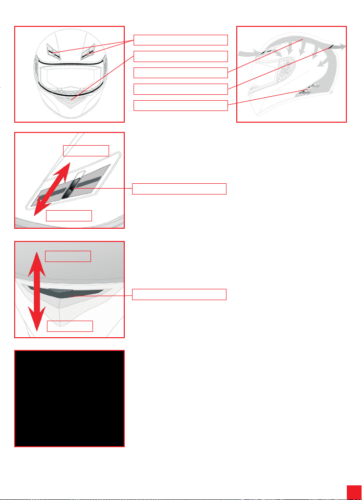
2) 換気システム
閉じる
開く
フロント吸気口
鼻部吸気口
ポリスチレン貫通チャネル
上部吸気口
側面エア出口
2.1) 吸気口を開く/閉じる
上部吸気口を開くには、カーソルをカチッと音がするまで動かします。
カーソル
閉じる
開く
2.2) チンストラップ吸気口を開く/閉じる
チンストラップ吸気口を開く、または閉じるには、吸気機構を上げるか下げます。
機構
2.3) ノーズガードの取り外し/取り付け
ノーズガードは取り外すことができます。ハウジングからゆっくりと引き抜きます。再度取り
付けるには、プラスチックバンドをハウジングに挿入し、固定されていることを確認しま
す。
Page 46
46
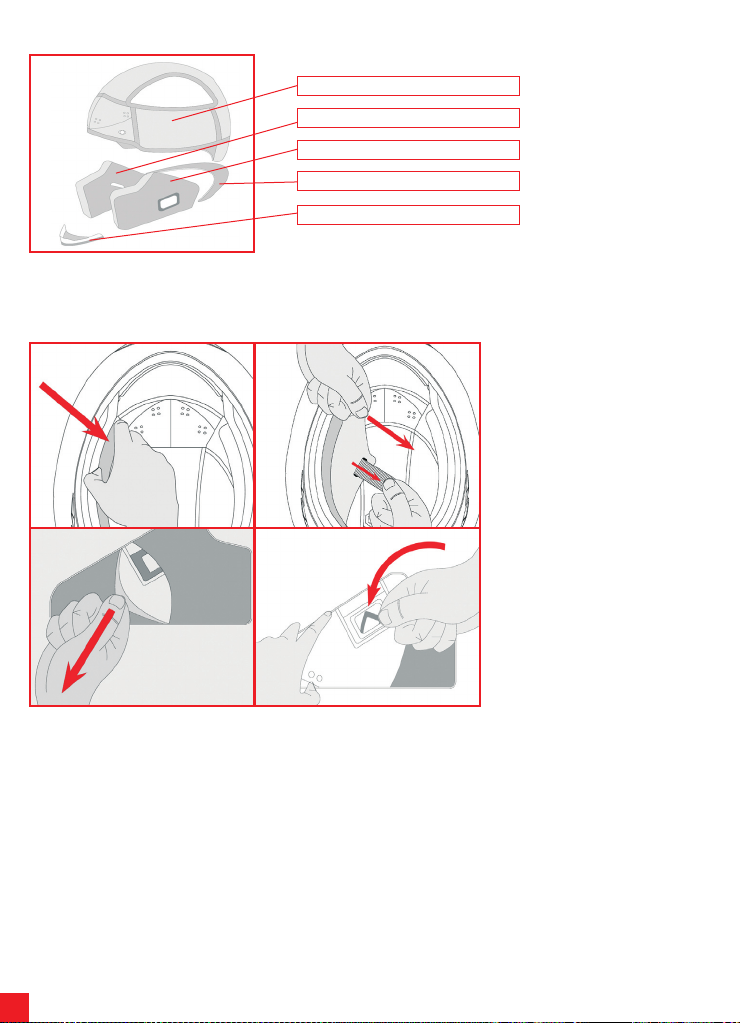
3) インナー
キャップ
右チークパッド
左チークパッド
ネックガード
スロートウィンドシールド
キャップ、左右チークパッドおよびウィンドシールドは取り外して洗浄することができます。インナーの取り付け、取り外しの際は、指示に従
い、以下の図をよく見てください。インナーの洗浄については、「安全上のご注意」の小冊子を参照してください。
1 2
3 4
3.1) チークパッドの取り外し/取り付け
チークパッドを取り外すには、ヘルメットの
チンストラップに近い部分のパッドを握っ
て、矢印の向きに引っ張ります(1)。チーク
パッドを取り外し、固定ストラップを穴に通
して引っ張ります(2)。布カバーを取り外す
には、背面(3)からスロートストラップのリ
ングファスナーをひねって取り外します
(4)。
Page 47
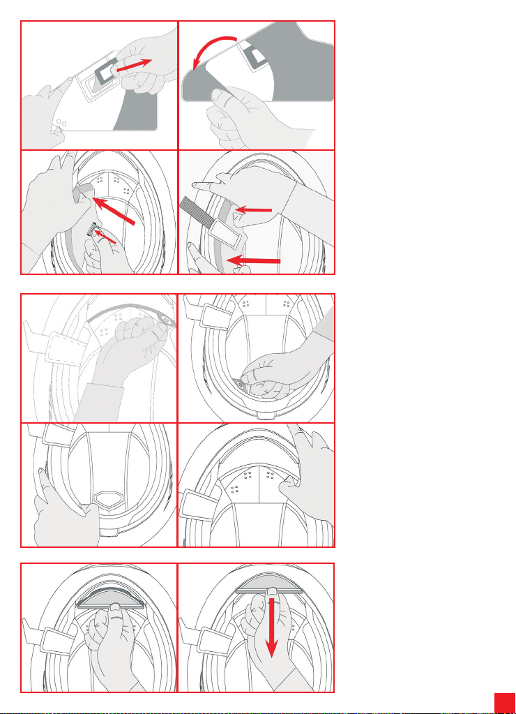
47
1 2
3 4
チークパッドを取り付けるには、長方形のリ
ングファスナー(1)を挿入した後、チークパ
ッドに布カバーをかぶせて(2)、チークパッ
ドとカバーが正しく組み合わされているこ
とを確認します。 チークパッドをヘルメット
に入れ、ストラップを適切な穴に通します
(3)。チークパッドの後ろ側を先に挿入し、
続いて前の部分を挿入します(4)。チークパ
ッドがヘルメットに完全に固定されている
ことを確認します。
1 2
3 4
1 2
3.2) キャップの取り外し/取り付け
キャップを取り外すには、ヘルメット前面の
2つのプレススタッド(1)、およびヘルメット
背面の2つのプレススタッド(2)を解放し、ヘ
ルメットの外に取り出します。
NB キャップの損傷と布部分の破損を防止
するために、すべてのプレススタッドを解放
してからキャップを引き抜くようにします。
キャップを元に戻すには、キャップをヘルメ
ットの中に挿入し、2つのプレススタッドを
背面(3)、2つのスタッドを前面(4)の所定の
位置に留めます。
3.3) スロートウィンドシールドの取り外
し/取り付け
布製のシールドを取り付けるには、プラスチ
ックバンドをチンストラップの空間に挿入し
ます。
シールドを取り外すには、外に向かって矢
印の向きに引っ張ります。
Page 48
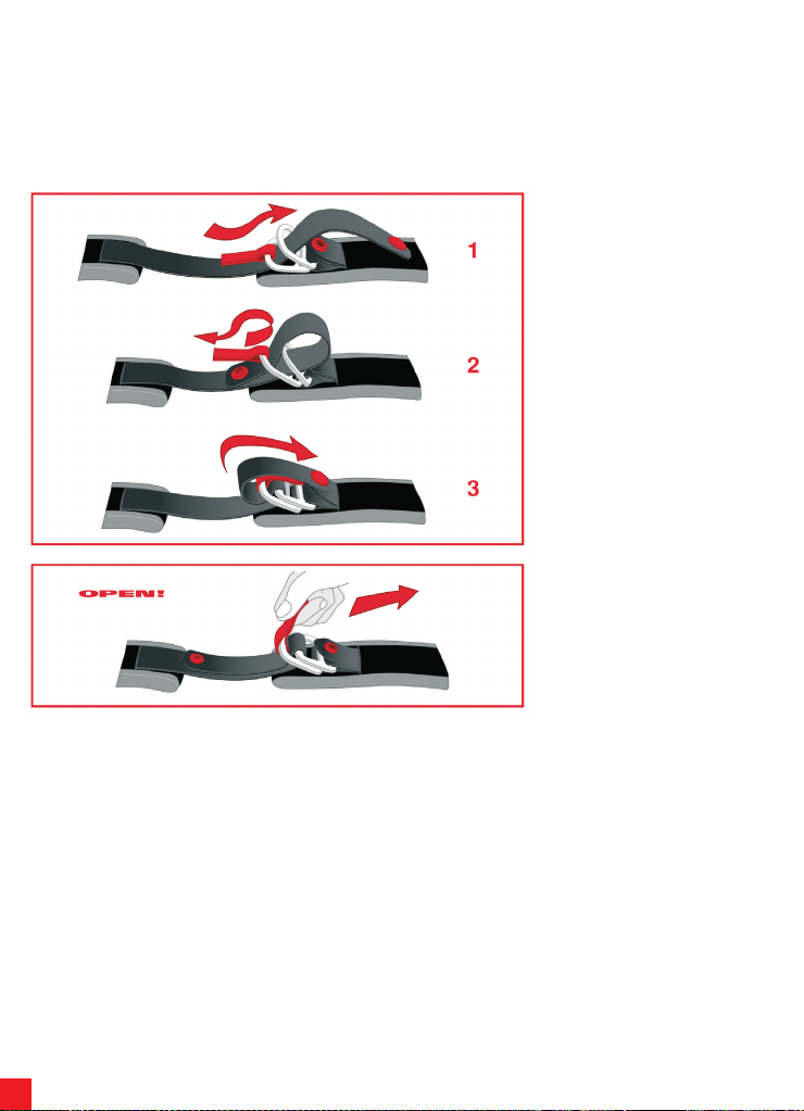
48
4) リテンションシステム
リテンションシステムは3タイプあります。
- DD
- クイックリリースバックル
- マイクロメトリック調整
これら3タイプの使用方法を以下に示します。
4.1) DDリテンションシステム
ヘルメットを固定するには、2つのリング
(1)にテープを差し込み、ストラップがジョー
を押し付けるまでテープ(2)の端を引き、フ
ラップ防止プレススタッド(3)を所定の位置
でカチッと留めます。図参照。
ヘルメットがしっかりと固定されていること
を確 認 して 下 さい( 小冊 子『 Sa fe ty
Warning』の「正しいヘルメットの選択」の
項を参照してください)。
ヘルメットを取り外すには、テープの端を引
っ張ってプレススタッドを解放し、テープを
弛めます。次に赤いタブを使用して、リング
を通してテープを引っ張ります。
Page 49
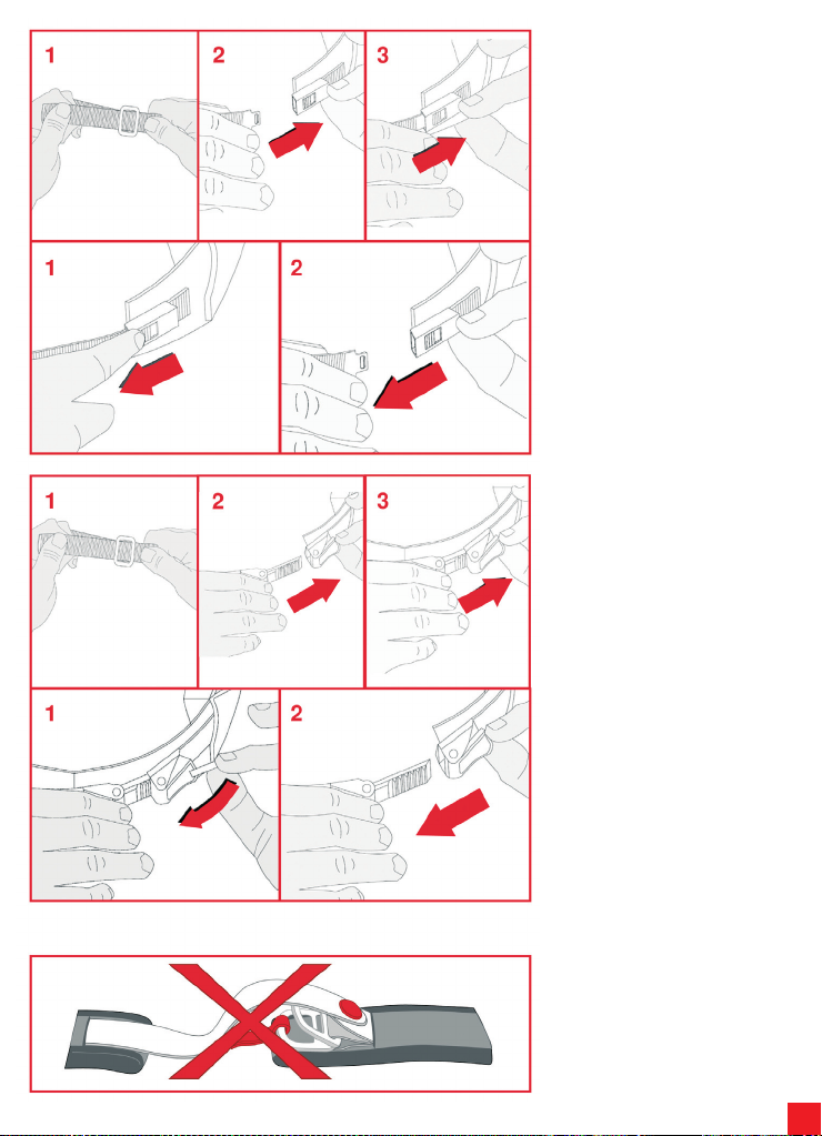
49
4.2) クイックリリース・バックル・リテンシ
ョンシステム
クイックリリース・バックル・リテンションシ
ステムでは、固定する前にストラップを調整
する必要があります。
下図に従い、メタルリング(1)を通過するテ
ープ部分を長くしたり短くしたりしてストラ
ップの長さを調節し、ストラップを固定した
ときにヘルメットがしっかり固定されるよう
にします。
ヘルメットを固定するには、バックルを、リテ
ンション機構(2)に差し込み、カチッと留め
ます(3)。
ヘルメットがしっかりと固定されていること
を確 認 して 下 さい( 小冊 子『 Sa fe ty
Warning』の「正しいヘルメットの選択」の
項を参照してください)。
ヘルメットを取り外すには 、赤いボタン
(1)を使用して、リテンション機構を開き、次
に、バックル(2)を開きます。下図参照。
4.3) マイクロメトリック調節リテンション
システム
マイクロメトリック調節リテンションシステ
ムでは、固定する前にストラップを調整する
必要があります。
下図に従い、メタルリングを通過するテープ
部分を長くしたり短くしたりしてストラップ
の長さを調節し(1)、ストラップを固定したと
きにヘルメットがしっかり固定されるように
します。
ヘルメットを固定するには、メタルバックル
にセレーションタブを差し込み(2)、できる
限り押し込んで(3)ストラップがジョーを押
しつけるようにします。マイクロメトリック調
節によって、セレーションタブ上で好きな番
号位置を選択することができるため、より深
く、正確に快適さを「キャリブレーション」す
ることが可能です(タブはできるだけ深くバ
ックルに挿入することが最も推奨されま
す)。
ヘルメットがしっかりと固定されていること
を確 認 して 下 さい( 小冊 子『 Sa fe ty
Warning』の「正しいヘルメットの選択」の
項を参照してください)。
ヘルメットを取り外すには、リボンを用いて
赤いレバーを持ち上げ(1)、次にバックルを
開きます(2)。参照。
注意: リテンションシステム上に配置され
たボタン/ベルクロは、留め具ではなく、フ
ラップの防止だけを目的にしたものです。
これらを、ストラップを固定するための代
用品として使用しないようにしてくださ
い。
Page 50

50
.....................................................................................................
.....................................................................................................
.....................................................................................................
.....................................................................................................
.....................................................................................................
.....................................................................................................
.....................................................................................................
.....................................................................................................
.....................................................................................................
.....................................................................................................
.....................................................................................................
.....................................................................................................
.....................................................................................................
.....................................................................................................
.....................................................................................................
.....................................................................................................
.....................................................................................................
.....................................................................................................
.....................................................................................................
.....................................................................................................
.....................................................................................................
.....................................................................................................
.....................................................................................................
.....................................................................................................
.....................................................................................................
.....................................................................................................
.....................................................................................................
.....................................................................................................
.....................................................................................................
.....................................................................................................
.....................................................................................................
.....................................................................................................
Page 51

51
.....................................................................................................
.....................................................................................................
.....................................................................................................
.....................................................................................................
.....................................................................................................
.....................................................................................................
.....................................................................................................
.....................................................................................................
.....................................................................................................
.....................................................................................................
.....................................................................................................
.....................................................................................................
.....................................................................................................
.....................................................................................................
.....................................................................................................
.....................................................................................................
.....................................................................................................
.....................................................................................................
.....................................................................................................
.....................................................................................................
.....................................................................................................
.....................................................................................................
.....................................................................................................
.....................................................................................................
.....................................................................................................
.....................................................................................................
.....................................................................................................
.....................................................................................................
.....................................................................................................
.....................................................................................................
.....................................................................................................
.....................................................................................................
Page 52
AGV SpA
Strada Savonesa 12 - 15050 Rivalta Scrivia (AL) Italy
Phone +39 0131 853.011 Fax +39 0131 853090
www.agv.it - [email protected]
52
 Loading...