

Agusta MV F4 750 Service Manual 041-060
- 41 -
CONTROLS AND INSTRUMENTS 3
3
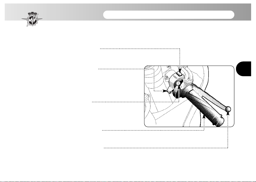
3.4 Handlebar controls, right side
Engine stop switch
Stops the engine and prevents it from being restarted.
Engine start button
Starts the engine. To be released as soon as the engine starts.
When the engine is running, pressing the button selects the dis-
play functions.
Cold start (choke) lever
Rotate clockwise when cold starting. After a few seconds, bring
the lever back to the home position.
Throttle twist grip
Rotate to control the engine fuel supply.
Front brake lever
Pull to the handgrip to operate the front brake.

- 42 -
CONTROLS AND INSTRUMENTS 3
3
Engine stop switch
It is used to switch off the engine in an emergency. The ignition circuit is disabled, preventing the engine
from being restarted. To be able to restart the engine, bring the switch back to the home position.
NOTE
Under normal conditions, do not use this switch to shut off the engine.
Engine start button
It is used to start the engine and, when the engine is running, to select the different functions of the display installed on the instrument panel.
DANGER
To a void damaging the electrical equipment,be sure not to hold down the button for longer
than 5 consecutive seconds.
If, after several attempts, the engine does not start, refer to the chapter “TROUBLESHOOTING” later in this manual.
Cold start (choke) lever
It facilitates cold starts by acting on the fuel supply.

- 43 -
CONTROLS AND INSTRUMENTS 3
3
NOTE
This function must remain active only for a short time depending on the engine and outside temperatures. As soon as the idle speed keeps the engine running, it is advisable to disable the control.
Throttle twist grip
It controls the fuel supply, making it possible to change the speed of the engine. To operate the device,
rotate the handgrip from the home position, corresponding to the idle speed.
When cold starting (choke on), rotating the handgrip towards the throttle closing position brings the
choke lever back to the home position.
Front brake lever
It controls a hydraulic circuit that operates the front wheel braking system.
- 44 -
CONTROLS AND INSTRUMENTS 3
3
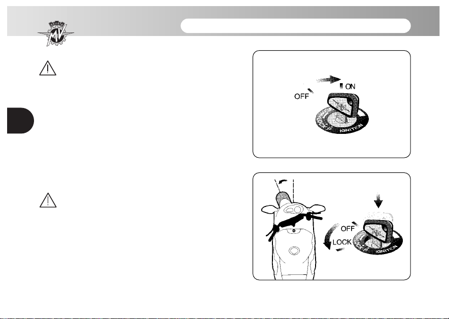
3.5 Ignition switch and steering lock
Danger - Warning: Do not attach a ring or any
other object to the ignition key as they may
hinder the steering action.
The ignition switch enables and disables the electrical
circuit and the steering lock. The four positions of the
switch are described below.
OFF position
All electrical circuits are deactivated. The key can be
extracted.
ON position
All electrical circuits are activated. The instruments and
warning lights perform the self-diagnostic cycle. The
engine can be started. The key cannot be extracted.
WARNING
Never attempt to change the switch functions
while riding, as you may lose control of the
vehicle.
LOCK position
Turn the handlebar to the left or right. Press the key in
gently while rotating it to the LOCK position.
All electrical circuits are deactivated and the steering is
locked. The key can be extracted.
- 45 -
CONTROLS AND INSTRUMENTS 3
3
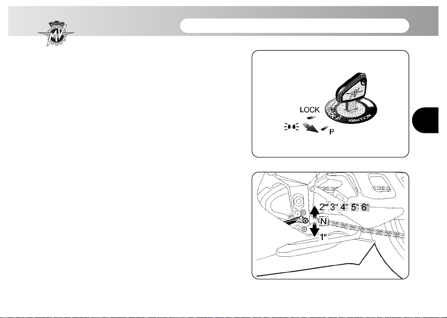
P (PARKING) position
Turn the key from the LOCK position to the P position.
All electrical circuits are deactivated except the parking
lights. The steering is locked. The key can be extracted.
3.6 Gear lever
The N (neutral) position is indicated by the related warning light on the instrument panel.
To change into first gear, shift the lever down.
To change into second gear, shift the lever up. Shifting
the lever up repeatedly engages all the other gears in
succession up to the sixth speed.
- 46 -
CONTROLS AND INSTRUMENTS 3
3
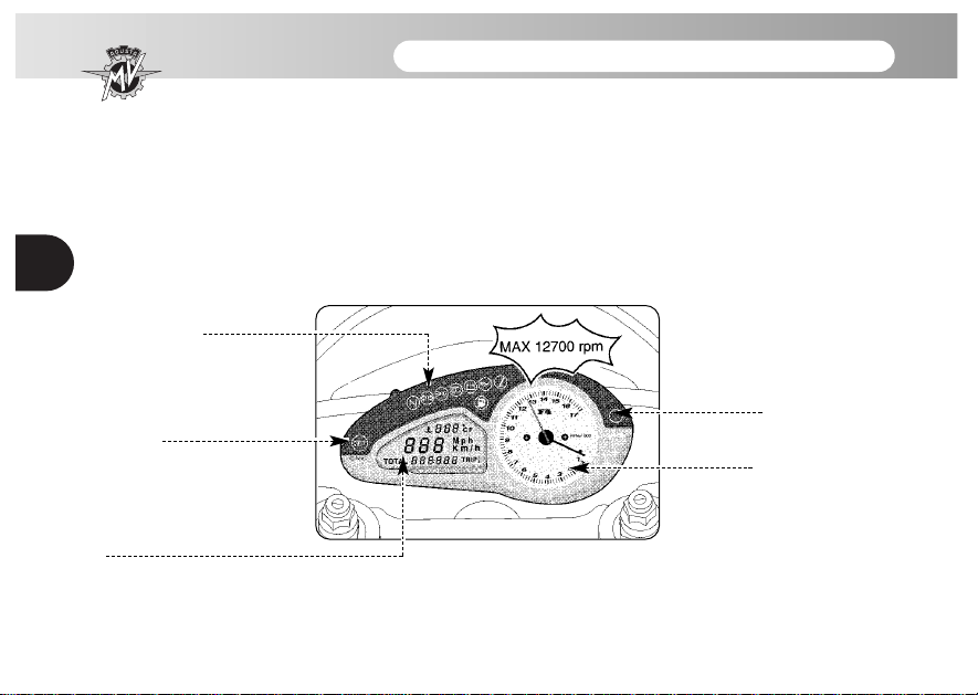
3.7 Instruments and warning lights
The instruments and warning lights are activated by turning
the ignition switch to the ON position. After a preliminary check
(approx. 7 seconds) the displayed information reflects the current general condition of the motorcycle.
Warning lights
(§3.7.1.)
SET button (§3.7.2.)
Multifunction display (§3.7.2.)
Warning light
(§3.7.1.)
Tachometer
 Loading...