

Page 1
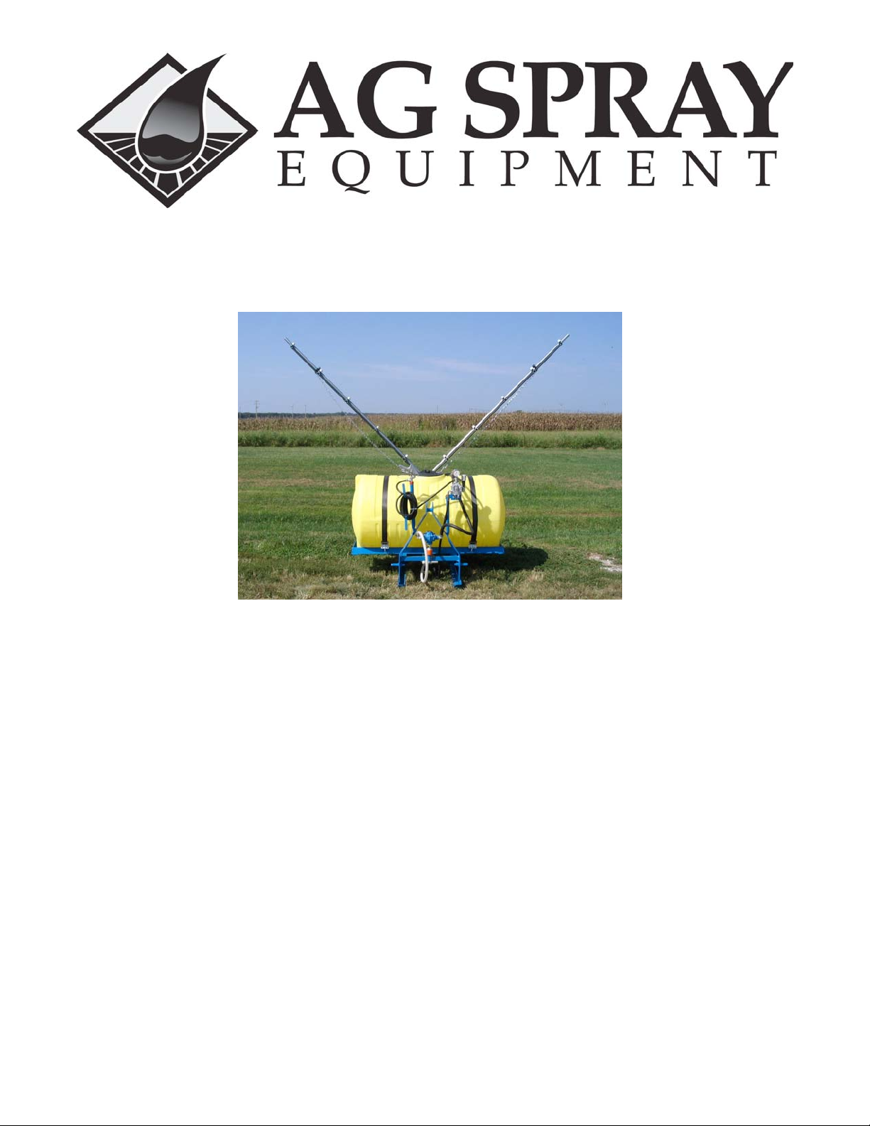
OWNERS MANUAL
RM 110, 150, & 200
8 ROLLER PUMP
HAMILTON #20,
BOOMJET #10, BOOM XT
AG 6 or 8 ROW DELUXE BOOM
1
Page 2

RM 110, 150, & 200
AG SPRAY EQUIPMENT OWNER’S MANUAL
Congratulations on purchasing your new three point hitch field sprayer. This manual is designed to aid you in operating your
new sprayer. Also enclosed is a parts breakdown and/or calibration chart for the following: roller pump, pressure regulator,
43L-AL spray gun, Hamilton nozzle, Boomjet nozzle, Boom X- tender nozzles & the 6 or 8 row deluxe boom.
WARRANTY
All Field Sprayers are under warranty by Ag Spray Equipment for a one year period from the date of purchase. This warranty
only applies to defects in workmanship or manufactures defects in their components. This warranty does not cover any misuse,
abuse, or parts that may freeze & break. Owners are responsible for these issues. Parts proven defective within the one-year
period will be replaced at no charge.
Ag Spray Equipment must be notified immediately of any defects or parts broken due to shipping on the sprayer. After the
one-year period all warranty is void. No product will be accepted for return without authorization. All returned goods must be
packaged securely and shipped with transportation charges prepaid.
For further information regarding parts or warranty, contact:
Ag Spray Equipment
1100 New Industry Lane
Hopkinsville, KY 42240
Phone: 1-800-637-7172
Operation & Instructions of New Sprayer
First, back your tractor up to the sprayer and let the lift arms all the way down. Insert the lift pins into the lift arms of the
tractor & secure with lock pins. Second, hook up the top link on the tractor to the very top
hole of the frame. Next, connect the pump to the PTO shaft on your tractor by pulling the orange coupler back while sliding it
onto the PTO shaft until the balls lock into the grooves on the shaft. After pump is secure take the chain & wrap it around the
drawbar of the tractor using the snap link to snap the chain together to keep pump from twisting hoses when PTO is engaged.
Next, fill the tank at least _ to _ full of plain water with no chemicals. Screw the pressure regulator (23120-3/4-PP, gray knob)
part of the way out & make sure agitation valve (V25B) is _ of the way open. This ensures that you do not overpressure the
gauge & break it. Also, make sure the valve under the tank is open (handle should be turned going w/ the line).
You are now ready to try out your sprayer. Engage PTO lever & pull throttle to the 540RPM mark on the RPM gauge. Turn
boom valve on & adjust to the desired operating pressure. Adjust pressure with the pressure regulator (gray knob) & not the
agitation valve because you need to keep agitation constant.
2
Page 3
CALIBRATING YOUR SPRAYER
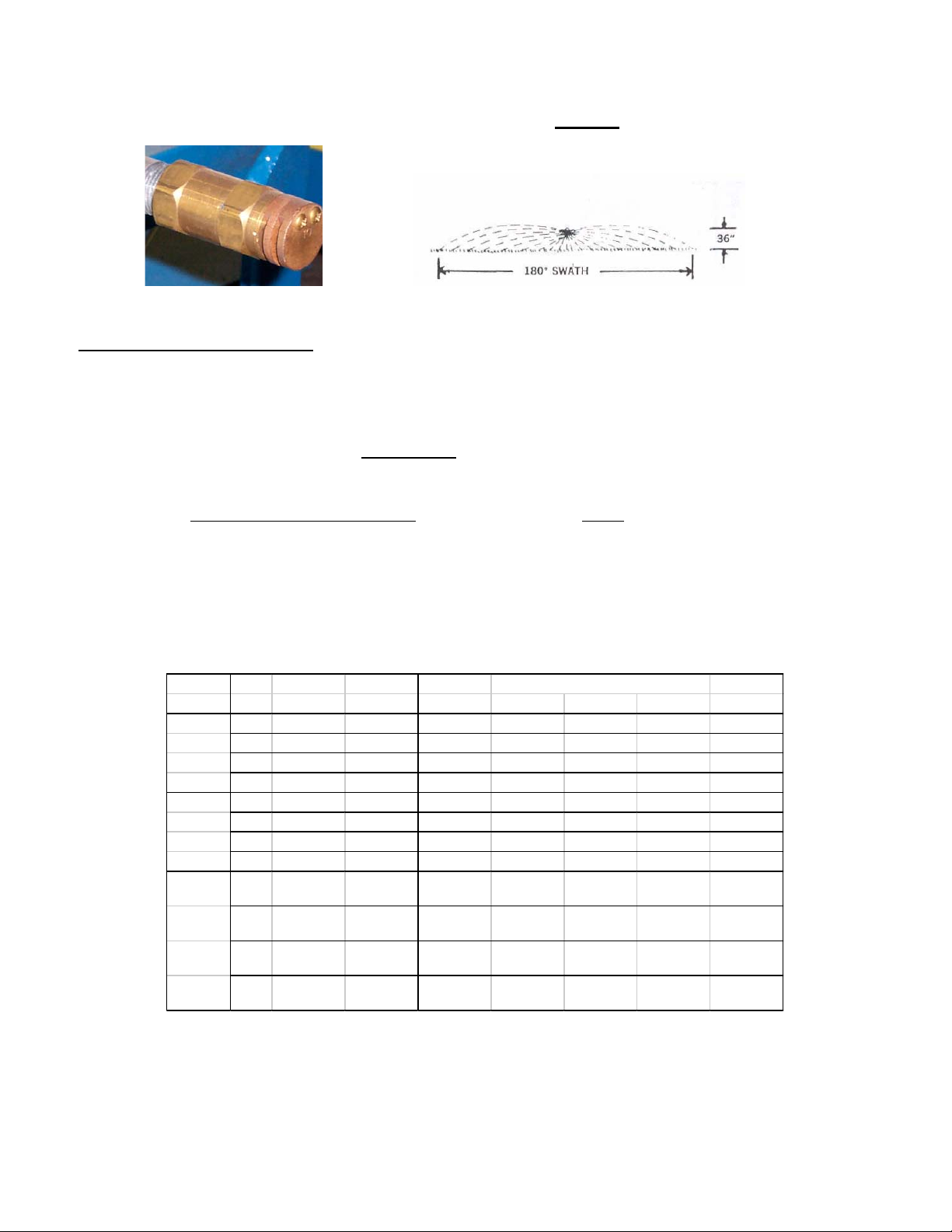
HAMILTON NOZZLE 654201
CALIBRATING YOUR SPRAYER
To determine pressure & GPA with a boomless nozzle use this calibration for it is different than a boom
calibration:
GPA = 495 X GPM
MPH x Swath in feet
EXAMPLE: 495(constant) x 4.2gpm=2079 2079 = 10.395 GPA
4mph x 50’swath=200 200
Refer to Chart
OPERATING DATA OF 180* NOZZLES
SPRAYERS ARE SUPPLIED w/ #20
Orfice GPM Swath GALLON PER ACRE
Number PSI 180* 180* 3 MPH 4 MPH 5 MPH 8 MPH 10 MPH
30 1.7 44' 6.4 4.8 3.8 2.4 1.9
#5 40 2.0 46' 7.2 5.4 4.3 2.7 2.2
50 2.2 48' 7.6 5.7 4.5 2.9 2.3
60 2.4 50' 7.9 5.9 4.8 3.0 2.4
30 3.7 50' 12.2 9.2 7.3 4.6 3.7
#10 40 4.2 50' 13.9 10.4 8.3 5.2 4.2
50 4.6 52' 14.6 10.9 8.8 5.5 4.4
60 5.0 52' 15.8 11.9 9.5 5.9 4.8
30 5.1 54' 15.6 11.6 9.3 5.8 4.7
#20 40 5.9 54' 18.0 13.5 10.8 6.8 5.4
50 6.7 56' 19.7 14.8 11.8 7.4 5.9
60 7.1 58' 20.2 15.1 12.1 7.6 6.1
GPM = Gallons Per Minute
GPA = Gallons Per Acre
MPH = Miles Per Hour
PSI = Pressure Per Square Inch
3
Page 4
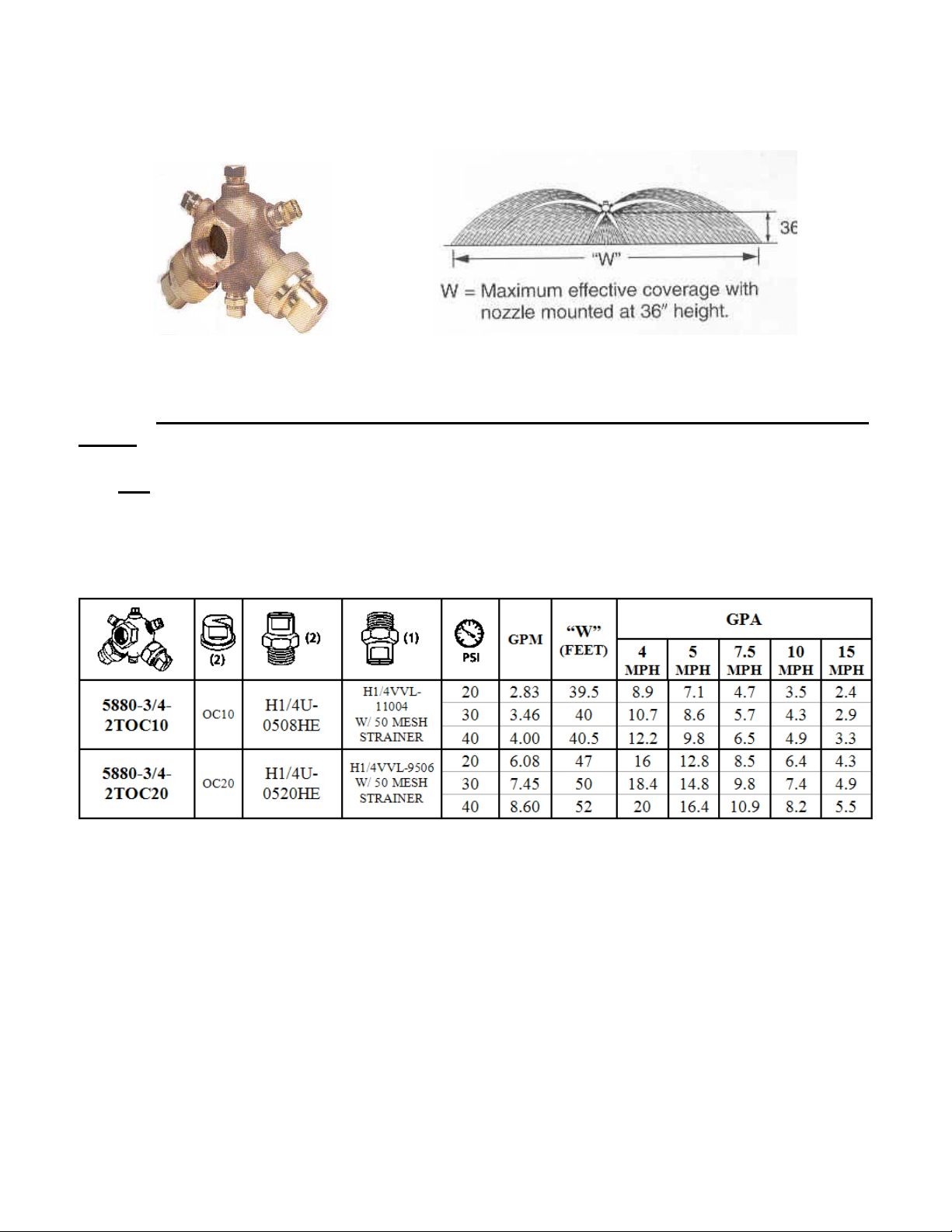
SPRAYING SYSTEMS 5880 BOOMJET NOZZLE
*NOTE: BOOMJET SPRAYERS ARE STANDARD w/ #10 NOZZLES & a HYPRO 8 ROLLER
PUMP.
IF A #20 NOZZLE IS USED THEN YOU NEED TO GO TO A HYPRO 5 ROLLER PUMP & 1”
PLUMBING (BECAUSE OF THE VOLUME NEEDED).
4
Page 5
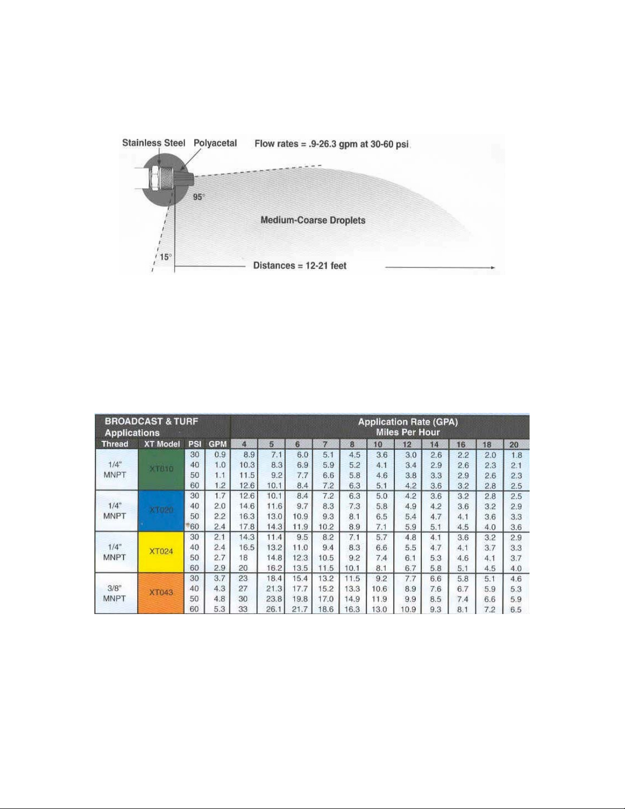
HYPRO BOOM X TENDER TIPS
Recommended Spray Height is 48”
*NOTE: YELLOW TIP-XT024 IS USED.
5
Page 6
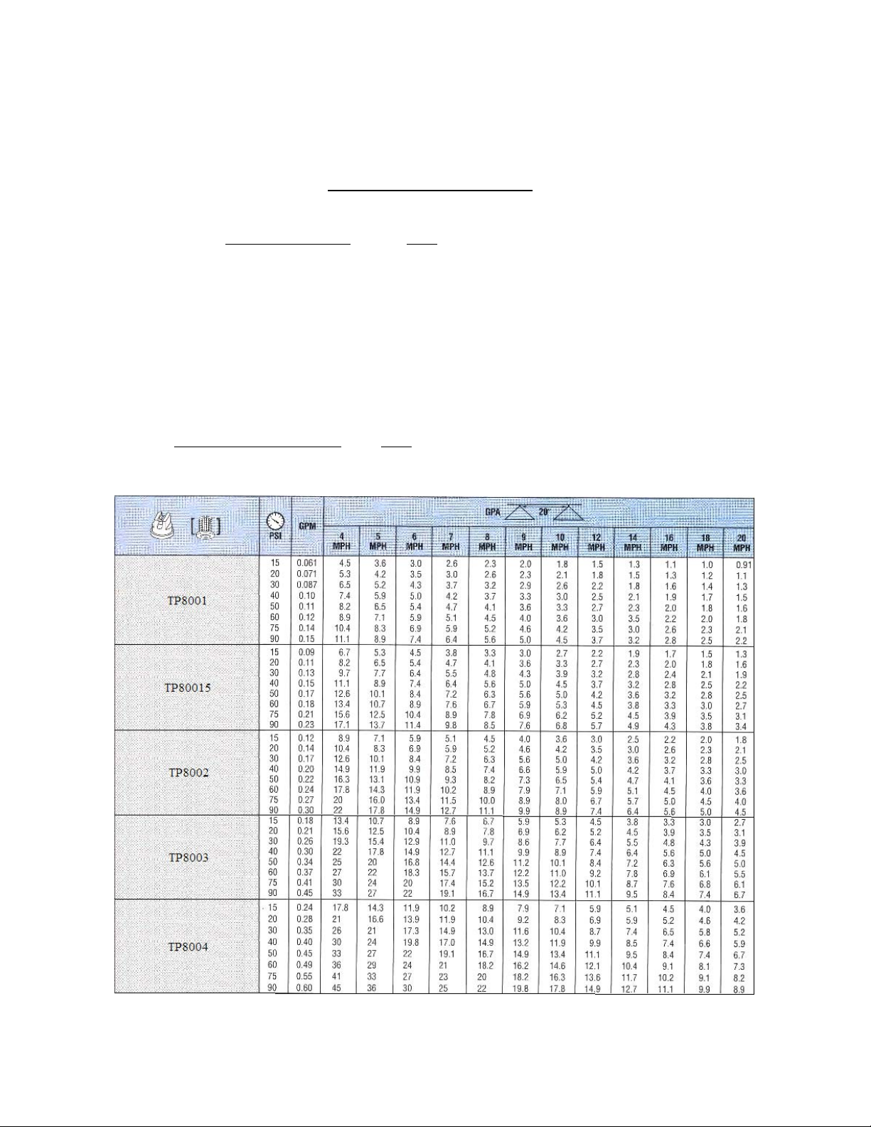
TEEJET SPRAY TIP CALIBRATION
BA6D & BA8D
All standard booms come w/ 8003VP poly tips.
Formula: GPA x MPH x Nozzle Spacing
5940
Example: 20gpa x 4mph x 20” = 1600
5940 5940
Take the GPM that you figured & look down the GPM chart to figure what pressure you need to run at that desired
speed.
*NOTE: If spraying liquid nitrogen you will need to multiply the conversion factor w/ the gpa, mph, & nozzle
spacing.
Conversion Factor: 28% Nitrogen - 10.65 lbs. per gal. - 1.13
32% Nitrogen - 11.00 lbs. per gal. - 1.15
Ex. 20gpa x 4mph x 20” x 1.13 = 1808
5940 5940
= .27gpm
= .31gpm
6
Page 7
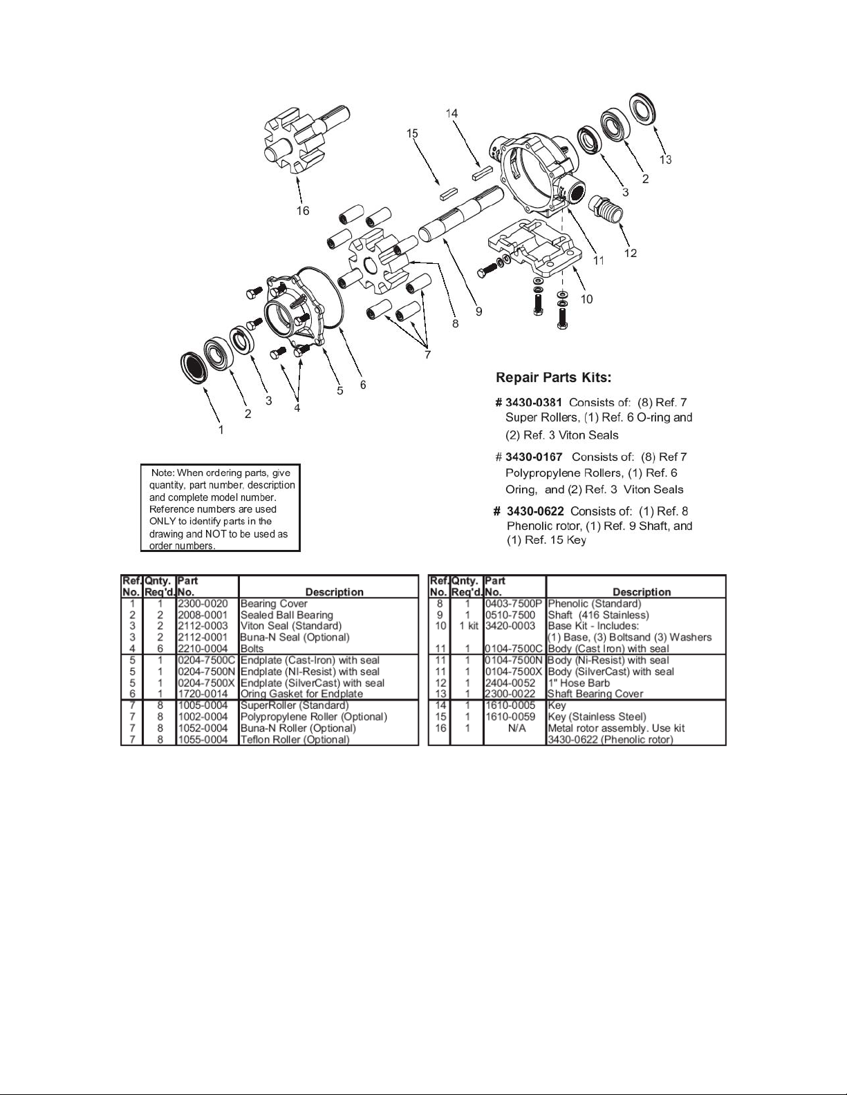
HYPRO 7560C, 7560N, & 7560XL
7
Page 8
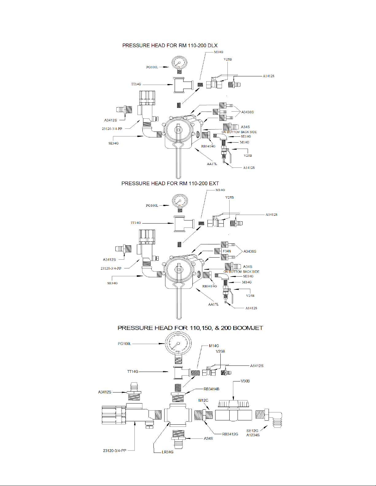
PRESSURE HEAD FOR 6 & 8 ROW DELUXE BOOMS
8
Page 9
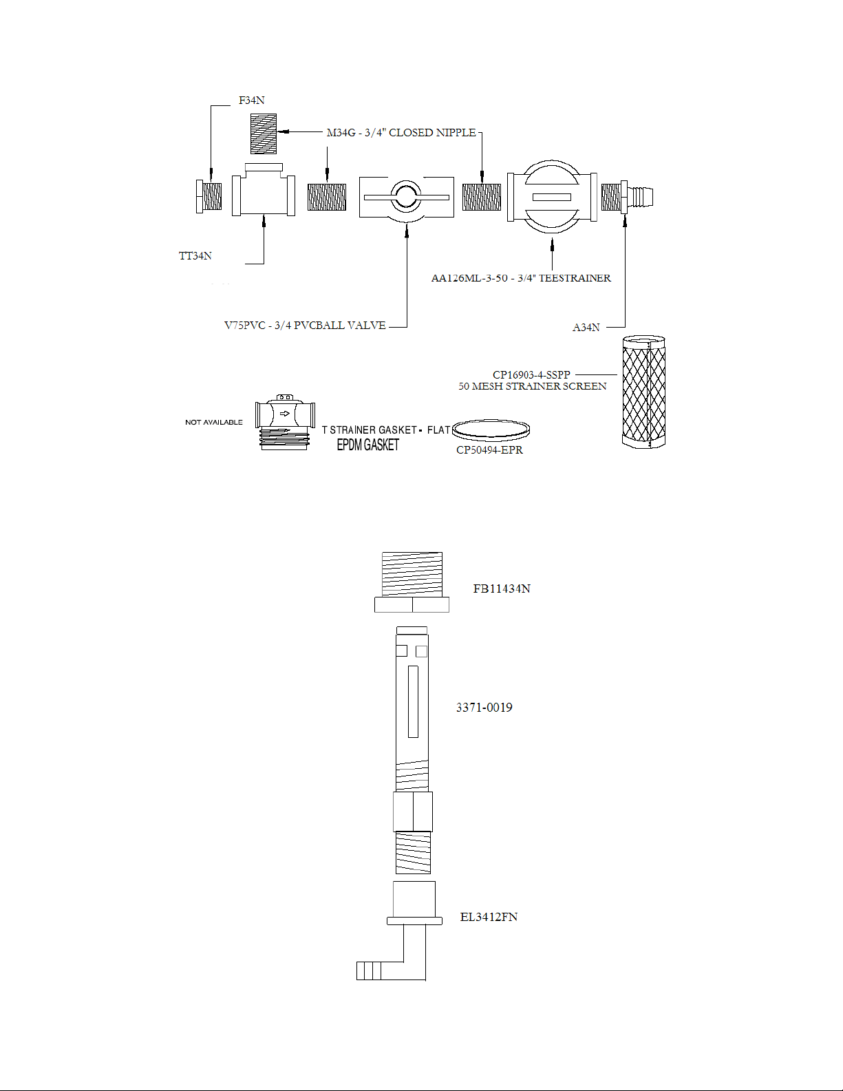
TANK PLUMBING
AGITATOR KIT
9
Page 10
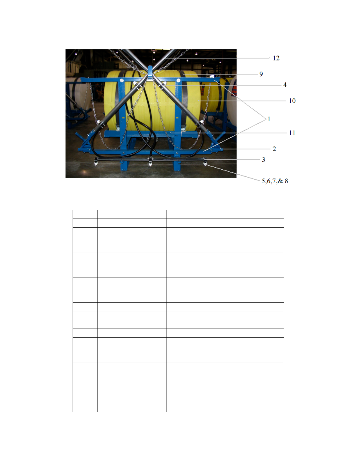
ROUND TANK
BA6D – 6 Row (21’) Booms have 13 Nozzles
BA8D – 8 Row (28’) Booms have 17 Nozzles
ITEM
1
2
3
4
5
6
7
8
9
10
11
12
PART NO. DESCRIPTION
WSBF 6 or 8 Row Back Frame
BRHINGE Breakaway Hinge
18635-111-406-NY 3/8” Quick Jet Elbow
4 of these on a 6 or 8 Row Boom
18636-112-406-NY 3/8” Quick Jet Tee
8 of these on a 6 Row
12 of these on an 8 Row
CP25611-2-NYR Quick Jet Slotted Cap
6 Row – 13 Caps
8 Row – 17 Caps
TP8003VP Poly Tip
8079-PP-50 50 Mesh Poly Screen
CP19438-EPR Cap gasket
TASTRAP Strap Kit 110-300gal.
TA110HY30
TA150HY30
TA200HY32
WS200RK
WS110CRADLE
WSE150CRADLE
WS200CRADLE
110 gal. Horizontal
150 gal. Horizontal
200 gal. Horizontal
Rack for 110, 150, & 200 gal.
Cradle for 110
Cradle for 150
Cradle for 200
TU114ALR 1 _” Aluminized Tubing
6 Row – 7’6”per side / 8 Row – 11’
10
Page 11
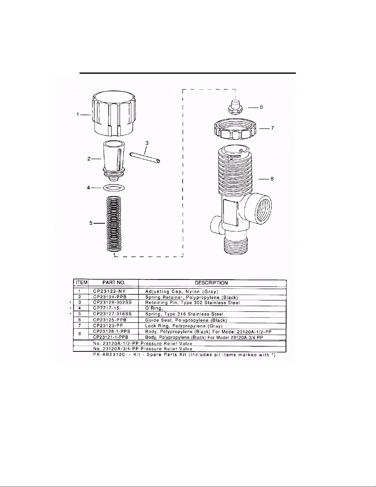
SPRAYING SYSTEMS 23120 REGULATOR
11
Page 12
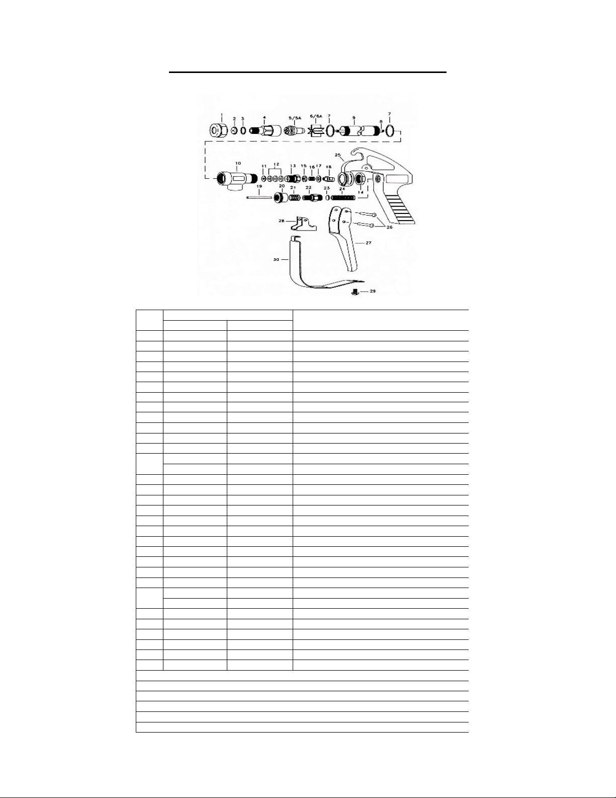
SPRAYING SYSTEMS 43L-AL SPRAY GUN
PART #
ITEM BRASS ALUMINUM DESCRIPTION
1 CP1325 CP1325-AL CAP, BRASS, or ALUMINUM
2 D-** D-** ORIFICE DISC, HARDENED STAINLESS STEEL
3 CP4743-NY CP4743-NY GASKET, NYLON
4 CP10566 CP10566-AL NOZZLE HOUSING, BRASS or ALUMINUM
5A 10565 10565-AL SEAT PLUG ASSEMBLY - BRASS or ALUMINUM
6 CP10571-2-NYB CP10571-3-NYB GUIDE VANE, NYLON
6A CP10571-AL GUIDE VANE, ALUMINUM
7 CP45195-NYB CP45196-NYB GASKET, NYLON (2 REQUIRED)
8 CP19238-416SS CP19238- 416SS STEM, TYPE 416 STAINLESS STEEL
9 CP6604 CP6604-AL TUBING, BRASS or ALUMINUM
10 CP6942 CP6942-AL INLET BODY, BRASS or ALUMINUM
11 CP6601-302SS CP6601-302SS PACKING WASHER, TYPE 302 STAINLESS STEEL
12 CP6602-LEA CP6602-LEA PACKING LEATHER ( 3 REQUIRED)
CP6602-TEF CP6602-TEF PACKING TEFLON (3 REQUIRED)
13 CP19237 CP19237-AL PACKING SCREW, BRASS or ALUMINUM
14 CP6599 CP6599-IZP LOCKNUT, BRASS, or STEEL ZINC PLATED
15 CP9641-INP CP9641-INP STEM NUT, STEEL NICKEL PLATED
16 CP6595-SS CP6595-SS TRIGGER STOP SPRING, SS
17 CP7991-SS CP7991-SS WASHER, SS
18 CP6597-INP CP6597-INP TRIGGER GUIDE, STEEL NICKEL PLATED
19 CP6591-SS CP6591-SS SPRING STUD, STAINLESS STEEL
20 CP6589-IZP CP6589-IZP STOP ADJUSTMENT NUT, STEEL ZINC PLATED
21 CP6594-SS CP6594-SS SPRING FOR STOP ADJUSTMENT NUT, SS
22 CP6588-IZP CP6588-IZP SPRING SCREW, STEEL ZINC PLATED
23 CP6592-302SS CP6592-302SS SPRING GUIDE WASHER, TYPE 302 SS
24 CP6593-1-SS CP6593-1-SS MAIN SPRING, SS for MODEL 43L
CP6593-2-SS CP6593-2-SS MAIN SPRING, SS for MODEL 43H
25 CP14477-1-AL CP14477-1-AL HANDLE BODY, ALUMINUM
26 CP7623-IZP CP7623-IZP RIVET, STEEL NICKEL PLATED
27 CP6509-INP CP6509-INP TRIGGER, STEEL NICKEL PLATED
28 CP6510-INP CP6510-INP TRIGGER STOP, STEEL NICKEL PLATED
29 CP11757-SS CP11757-SS SCREW, STAINLESS STEEL
30 CP13798-INP CP13798-INP TRIGGER GUARD, STEEL NICKEL PLATED
GUNJET No. AA43L - BRASS, FOR PRESSURE UP TO 200 psi
GUNJET No. AA43L-AL - ALUMINUM, FOR PRESSURE UP TO 200 psi
GUNJET No. AA43H - BRASS, FOR PRESSURES FROM 200 to 800psi
GUNJET No. AA43H-AL - ALUMINUM FOR PRESSURES FROM 200 to 800psi
PK-AB43-KIT SPARE PARTS KIT (includes all items marked)
PK-AB43-AL-KIT SPARE PARTS KIT (includes all items marked)
12
Page 13

TROUBLE SHOOTING
PROBLEM
1. NO PRESSURE
A. PUMP NOT PROPERLY PRIMED
B. STRAINER CLOGGED
C. PUMP SUCKING AIR or PUMP HAS
AIR LOCK. CHECK HOSES FOR
CRACKS or HOLES. MAKE SURE
FITTINGS ARE TIGHT.
D. SUCTION LINE COLLAPSING
TOGETHER – NEED STIFFER HOSE
E. WORN or LEAKING SEALS
2. PUMP RUNS, BUT LOW PRESSURE
3. PUMP PRESSURE GOOD BUT
LOW OUTPUT THROUGH
NOZZLES
4. EXCESSIVE VIBRATION or
NOISE
A. SUCTION LINE & FITTINGS
CLOGGED UP or HOSE KINKED
B. WORN ROLLERS
C. STOPPED UP STRAINER
A. NOZZLE SIZE MAY BE TOO SMALL.
CHECK CALIBRATION & GALLONS
PER ACRE
B. INLET LINE TOO SMALL or
BLOCKED OFF
C. BY-PASS OPEN TOO MUCH. CLOSE
VALVE SLIGHTLY
A. POSSIBLE LOOSE COUPLER OR
DAMAGED SHAFT
B. EXCESSIVE PTO or ENGINE SPEED
C. ROTOR or INTERNAL PROBLEM
13
 Loading...