

Ag Spray AG15COOPK User Manual
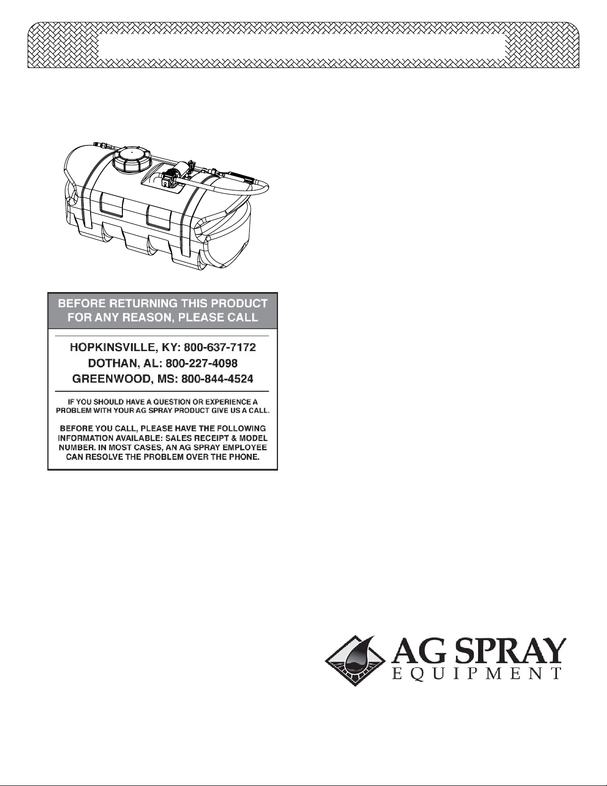
Owner's Manual
(15 Gallon Lawn & Garden Spot Sprayer)
•
•
•
•
Your sprayer has been mostly assembled at the factory. The
only requirement will be for you to hook up your battery
leads to a fully charged 12 Volt battery. The red wire must
be connected to the "hot" lead, and the black wire should be
connected to the ground.
Technical Specifications
15 Gal. Corrosion-Resistant Polyethylene Tank
12 Volt Diaphragm Pump, 1.0 g.p.m. - 35 p.s.i.
Squeeze-Lever Handgun
15 Ft. Handgun Hose
Assembly
Operation
General Information
Thank you for purchasing this product. The purpose of this
manual is to assist you in operating and maintaining your lawn
& garden spot sprayer. Please read it carefully, as it furnishes
information which will help you achieve years of trouble-free
operation.
Warranty/Parts/Service
Products are warranted for one year from date of purchase
against manufacturer or workmanship defects.
Commercial users have a 90 day warranty.
Your authorized dealer is the best source of replacement parts
and service. To obtain prompt, efficient service, always
remember to give the following information...
Your sprayer may be equipped with (2) ON/OFF switches.
One on the wire assembly that you hook up to your battery,
the other is on the pump itself, on the opposite end of the
pressure switch. The "-" is the "ON" position and the "o" is
the "OFF" position for the switches. Make sure both
switches are depressed in the "-" position for operation.
In addition to the ON/OFF switch, the pump is equipped with
an electronic pressure switch that is factory pre-set for it to
shut off at 35 p.s.i.. This switch assembly is the 'square box'
on the head portion of the pump.
Always fill the tank with a desired amount of water first, and
then add the chemical slowly, mixing as you pour the
chemical into the tank. You may use the handgun to spray
into the solution in order to mix the chemical and water.
Initially begin spraying by opening the handgun. This will
enable the air in the line to be purged through the handgun
tip, while building pressure.
The pumping system draws solution from the tank, through
the strainer/filter, and to the pump. The pump forces the
solution under pressure to the handgun and/or boom
nozzles.
Open the handgun by squeezing the handle lever.
•
Rotating the adjustable nozzle tip on the handgun will
•
change the tip pattern from a straight stream to a cone
pattern (finer mist).
- Correct Part Description and/or part number.
- Model number/Serial number of your sprayer.
Part descriptions and part numbers can be obtained from the
illustrated parts list section(s) of this manual.
Whenever you need parts or repair service, contact your
distributor/dealer first. For warranty work, always take your
original sales slip, or other evidence of purchase date, to your
distributor/dealer.
www.agspray.com
1100 New Industry Lane
Hopkinsville, KY 42240
P: 800-637-7172
F: 270-885-7392
Form No. 1990 [5008302 (02/10)] Printed in the U.S.A.
104 Eastman Street
Greenwood, MS 38930
P: 800-844-4524
F: 662-455-4442
1563 S. Oates Street
Dothan, AL 36301
P: 800-227-4098
F: 334-673-1974
After Spraying
Winter Storage
After use, fill the sprayer tank part way with water. Start the
sprayer, and allow the clear water to be pumped through
the plumbing system and out through the spray nozzles.
Refill the tank about half full with plain water and use
FIMCO Tank Neutralizer and Cleaner, and repeat cleaning
instructions above.
Flush the entire sprayer with the neutralizing/cleaning
agent, then flush out one more time with plain water. Follow
the chemical manufacturer's disposal instructions of all
wash or rinsing water.
For the boom, (if applicable) remove the tips and screens
from the nozzle assemblies. Wash these items out
thoroughly. Blow the orifice clean and dry. If the orifice
remains clogged, clean it with a fine bristle (NOT WIRE)
brush, or with a toothpick. Do not damage the orifice. Water
rinse and dry the tips before storing.
WARNING: Some chemicals will damage the pump
valves if allowed to soak untreated for a length of time!
ALWAYS flush the pump as instructed after each use.
Drain all water out of your sprayer, paying special
attention to the pump, handgun, and valve(s). These items
are especially prone to damage from chemicals and
freezing weather.
The sprayer should be winterized before storage by
pumping a solution of RV antifreeze through the entire
plumbing system. This antifreeze solution should remain in
the plumbing system during the winter months. When
spring time comes and you are preparing your sprayer for
the spray season, rinse the entire plumbing system out,
clearing the lines of the antifreeze solution. Proper care
and maintenance will prolong the life of your sprayer.
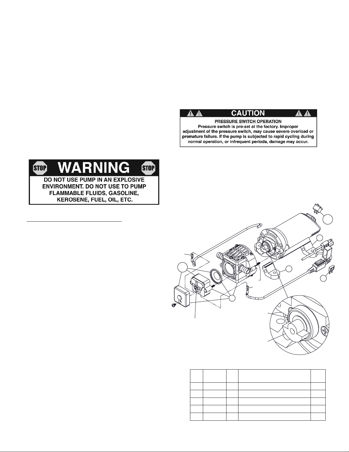
#5275702 Pump
(12 Volt, 4 Amp, 1.0 gpm, 35 psi)
Troubleshooting a 1.0 g.p.m. Pump:
Pump will NOT run:
- Check inline fuse on the wires on the pump. If blown,
replace with new fuse. (5 Amp mini-blade fuse...#5157204)
- Make sure BOTH on/off switches are in the 'on' position (-).
- Make sure you 12 volt source (battery) is fully charged.
- Insure a tight connection at the battery clips.
If none of the above will work, try pulling wire terminal "A" off
of the spade terminal of the pressure switch, and cross it
over and touch terminal "B". (You will need to remove the
pressure switch cap before doing this) If your pump runs
when you do this, you know you will need to replace your
pressure switch.
Another thing you can try is to take apart the switch box on
the lead wire assembly (#5274443) with the (2) phillips head
screws, and 'hot-wire' it together. Take the (2) wires that are
screwed to the rocker switch, off of the switch and twist
them together. This will insure you are getting the full 12
volts to the pump. If your pump runs after doing this, you will
know that your lead wire assembly needs to be replaced.
Pump runs, but does not prime:
- Check line strainer (screen) at the inlet location, at the
tank. You will need to unscrew the knurled nut to access
this screen. (see exploded view later in this manual) The
tank should be empty while performing this, otherwise you
may need to tilt the tank backwards a little bit so any
solution in the tank will be away from this inlet location.
Periodically take the screen at this location out and clean it.
- Unscrew (2) screws "S". This will allow you to inspect the
bearing and counterweight.
- Both the counterweight and the bearing need to spin
freely, and they both need to spin INDEPENDENT of each
other. If these 2 pieces are 'stuck' together, you will need to
break them free with some WD-40 or something similar and
this should restore most of your prime.
"A"
3.1
Pressure adjustment
screw (Factory Preset)
Item
No
1
2
3
3.1
4.1
Part
Number
5095202
5157204
5275531
5157201
5157207
"S"
"B"
3
Bearing
"Half-Moon"
counterweight
Description
Qty
1
Pump Foot (Pkg. of 4)
5 Amp Mini Fuse
1
1
Pump Assembly w/Pressure Switch
1
Pressure Switch w/Diaphragm
1
Rocker Switch
4.1
1
1
2
List
Price
4.99
3.99
37.95
23.95
6.99
Page 2
 Loading...