


1
USER MANUAL
Return the warranty certificate within
15 days together with a copy of the
invoice (without these documents the
warranty procedure cannot be
implemented).
DISC-O-MULCH
10/12m
Original Manual
AGRISEM INTERNATIONAL - 535 Rue Pierre Levasseur CS 60263 – 44158 ANCENIS CEDEX
Tel.: +33 (0)2 51 14 14 40 – Fax: +33 (0)2 40 96 32 36
NOTT-E-700 01/07/2016

2

3
FOREWORD
This manual is provided with your machine to enable you to make optimum use of your equipment, in
particular under safe working conditions.
All owners are reminded that the manual is an essential accessory which must remain with the
machine at all times, and that in the event of resale, article 1615 of the Civil Code requires that as
such it must be handed over to the new owner.
You are also reminded that as the manual is essential to the machine, all owners must undertake to
leave it physically available with the machine for all users to consult.

4

5
AGRISEM INTERNATIONAL - 535 Rue Pierre Levasseur CS 60263 – 44158 ANCENIS CEDEX
Tel.: +33 (0)2 51 14 14 40 – Fax: +33 (0)2 40 96 32 36

6

7
DECLARATION OF COMPLIANCE
WITH THE "MACHINERY" DIRECTIVE
The manufacturer referred to above certifies that the new equipment described below:
DISC-O-MULCH
Complies with the provisions of the amended "Machinery" directive (Directive 2006/42/CE) and with
the applicable national legislation.
ANCENIS,
21 May 2013
Michal Guzowski
Chief Executive Officer

8
Identification of the machine
This document should be kept inside this user manual
On receipt of the machine, please enter the corresponding information below:
Type of machine: .................................................................................
Serial number: ......................................................................................
Year of manufacture: ...........................................................................
Date of first use: ...................................................................................
Accessories: .........................................................................................
.............................................................................................................
....................................................................................................................................
Name of the Dealer: .............................................................................
Address: ...............................................................................................
.............................................................................................................
.............................................................................................................
Telephone number: ..............................................................................
AGRISEM INTERNATIONAL
535 Rue Pierre Levasseur CS 60263 – 44158 ANCENIS CEDEX
Tel.: +33 (0)2 51 14 14 40 – Fax: +33 (0)2 40 96 32 36

9
CONTENTS
1. INTRODUCTION ............................................................................................................................ 11
2. WARRANTY CONDITIONS ........................................................................................................... 12
2.1. EXCLUSIVE LIABILITY CLAUSE .......................................................................................... 15
2.2. COMPLIANT USE OF THE MACHINE ................................................................................. 16
2.3. SAFETY INSTRUCTIONS ..................................................................................................... 17
2.3.1.
Safety instructions ......................................................................................................... 17
2.3.1.1. Introduction ................................................................................................................ 17
2.3.1.2. Instructions to be followed before using the machine ............................................... 18
2.3.1.3. Instructions to be followed for hitching and unhitching .............................................. 19
2.3.1.4. Instructions to be followed before using the machine ............................................... 20
2.3.1.5. Instructions to be followed before carrying out any operations on the machine ....... 22
2.3.1.6. Instructions regarding installation .............................................................................. 23
2.3.1.7. Instructions regarding the hydraulic system .............................................................. 24
2.3.1.8. Instructions relating to the braking system ................................................................ 24
2.3.1.9. Instructions specific to AGRISEM seeders ................................................................ 25
2.3.1.10. Instructions relating to safety systems with spring assemblies ............................. 26
2.3.1.11. Instructions relating to transmission shafts with universal joints ........................... 26
2.3.1.12. Instructions relating to loading and transport ........................................................ 26
2.3.1.13. The user's workstation ........................................................................................... 26
2.3.1.14. Noise data .............................................................................................................. 26
2.3.2.
Safety symbols on the machine ..................................................................................... 27
3. TECHNICAL INSTRUCTIONS ....................................................................................................... 28
3.1. DISC-O-MULCH SETTINGS / USE ....................................................................................... 28
3.1.1.
Technical characteristics ............................................................................................... 28
3.1.2.
Hitching – Unhitching ..................................................................................................... 29
3.1.2.1. Tractor-mounted machine ......................................................................................... 29
3.1.2.2. Trailed machine ......................................................................................................... 30
3.1.3.
Folding and unfolding the extensions ............................................................................ 33
3.1.4.
Unfolding into the Work Position ................................................................................... 34
3.1.5.
Folding into the Transport Position ................................................................................ 35
4. Air Brake Coupling Procedure ........................................................................................................ 35
4.1. When Coupling ...................................................................................................................... 35
4.1.1.
When De-coupling ......................................................................................................... 35
4.1.2.
When driving on the road .............................................................................................. 36
4.2. Parking the machine .............................................................................................................. 36
4.2.1.
If the machine is to be left in the unfolded position ....................................................... 36
4.2.2.
If the machine is to be left in the folded position ........................................................... 36
4.3. Out-Rigger Wheels ................................................................................................................ 36
4.4. Work Settings ........................................................................................................................ 37
4.5. Transport wheel adjustment .................................................................................................. 37
4.5.1.
Adjusting the Transport Wheel Height ........................................................................... 37
4.5.2.
Adjusting the working depth using the roller .................................................................. 38
4.5.2.1. Adjusting the side deflectors on mounted and semi-mounted Disc-O-Mulch GOLD
machines 41
4.5.2.2. Adjusting the border spreading disk .......................................................................... 41
4.5.3.
4.6. SERVICING - MAINTENANCE ............................................................................................. 43
4.6.1.
4.6.2.
4.6.3.
4.6.4.
4.6.5.
4.6.6.
4.6.7.
4.6.8.
OPERATING RECOMMENDATIONS ........................................................................... 42
Servicing frequency ....................................................................................................... 43
Storage .......................................................................................................................... 43
Cleaning ......................................................................................................................... 44
Lubrication ..................................................................................................................... 44
Greasing ........................................................................................................................ 45
Maintenance .................................................................................................................. 45
Disks .............................................................................................................................. 47
Lighting system .............................................................................................................. 48

10

11
1. INTRODUCTION
The warranty certificate MUST be returned within 15 days of delivery of the machine to the final
user.
You have just taken ownership of your AGRISEM machine. It has been designed to give complete
satisfaction.
The equipment has been carefully designed using the latest technological solutions to reduce usage
costs.
However, for the best and most profitable use of your AGRISEM machine, please read this manual
carefully before starting it up and strictly follow the instructions. In particular, follow the instructions for
adjusting and servicing the machine, as well as the safety precautions, very carefully.
Please contact our distributor for any information or advice.
The instructions in this user manual must be read and applied by any persons who will be carrying out
work on or with the machine, in particular:
- Use of the machine (including preparation, repairs required during work and maintenance).
- Maintenance (servicing and inspection).
- Transport.
AGRISEM INTERNATIONAL cannot be held liable for personal injury or damage to equipment and
malfunctions resulting from failure to comply with the instructions given by the manufacturer in this
manual.
This user manual is an integral part of the machine and must always be kept with the machine,
especially in the event of resale.
AGRISEM INTERNATIONAL is constantly seeking to improve its products and reserves the right to
modify or improve its products with no obligation to apply these modifications or improvements to
products already on the market.
The instructions in this manual are not exhaustive and cannot cover all eventualities. The user must
comply with the applicable legislation, in particular with regard to safety, ensure that the rules of safety
and caution dictated by the situation are applied, use common sense and adapt the use of the
machine to the circumstances.
It is the Purchaser’s responsibility to check that the AGRISEM machine complies with the legislation
and regulations applicable to its final destination.

12
2. WARRANTY CONDITIONS
The warranty conditions applicable to machines fitted exclusively with genuine spare parts from
AGRISEM INTERNATIONAL are as follows:
DURATION
• If a defect is observed on a structural part within a period of 12 months as from the date of
delivery of the machine, and if this defect is due to faulty raw materials, or its manufacture at the
factory. The parts alleged to be faulty must be returned to the Company's address for an expert
inspection.
The following shall be considered to constitute proof of the date of delivery of the equipment:
- the date of the delivery slip and the purchaser’s invoice.
- the return of the warranty certificate within 15 days (with the dealer's and purchaser’s stamp
and signature) following delivery of the equipment.
MACHINES AND PARTS CONCERNED
• For the purposes of this warranty, the term “Machine” is exclusively used to designate machines
and parts manufactured by AGRISEM INTERNATIONAL. (It does not include external
components, in particular tyres, hydraulic hoses, etc. even though these parts are also supplied by
the Company)
• The warranty is void if any modifications have been made to the machine without
the formal agreement of AGRISEM INTERNATIONAL or if parts other than those
manufactured by the Company have been fitted (e.g. counterfeit wear parts).
EXTENT OF THE WARRANTY
• The warranty is limited to the reimbursement or repair of parts recognised as faulty with regard to
their raw materials or machining, in our factories by our Technical Departments.
• Any costs linked to the dismantling and replacement of the faulty part are not covered by the
warranty. The cost of transporting machines or machine parts to the place of repair and their
return to their owner is not covered either.
• Wear parts are not covered by the warranty.
PRECONDITIONS
The machine must be maintained and used in accordance with the instructions in this User Manual.
All of the safety measures described in the User Manual and in the manuals of any additional
equipment must be complied with.
All of the protection and safety devices and hazardous parts (e.g. shock absorbers) must be regularly
inspected and replaced if necessary.
The warranty is only valid if the customer has met the contract's general obligations, in particular the
payment conditions.

13
WARRANTY EXCLUSIONS
The warranty does not of course apply to:
- Faults due to normal wear, incorrect use, lack of maintenance, inadequate monitoring or
negligence.
- If the machine is damaged by an accident or develops a fault due to being used for purposes
other than those specified by AGRISEM.
- In the event of non-compliant use of the machine. Please consult chapter 3 with regard to this
point: Compliant use of the machine.
- If the manufacturer's instructions and requirements given in this manual are not complied with,
particularly those regarding safety, assembly, use, operation and servicing.
- In the event of improper handling on the part of the user.
- Causes due to the presence of foreign bodies.
- In the event of damage due to the machine being combined with other machines or
instruments without the prior written agreement of AGRISEM, and/or without complying with
the instructions given by the manufacturers of the tractor and other instruments or machines.
- If the machine is used with protection and safety devices that are incorrectly fitted or not
working.
- If the machine has been modified without prior written permission from AGRISEM, or if spare
parts, accessories or equipment have been fitted to the machine which were not
recommended by AGRISEM.
- In the event of non-compliant repair.
- If faults are due to the machine being immobilised.
- In the event of damage during transport or handling by a carrier. It is the recipient’s
responsibility to lodge the necessary complaints with the carrier.
- The adverse consequences of the machine being immobilised due to a fault or incident on the
machine are not covered by the warranty.
- Personal injury to the owner or a third party and the indirect consequences resulting from this
are not covered by the warranty.
Moreover, AGRISEM INTERNATIONAL shall not be liable for the payment of compensation for
any reason whatsoever in the event of the loss of crops or any damage whatsoever due to a fault,
hidden defect or machine breakdown.
The purchaser is always responsible for the choice of product and the suitability of the machine for
the result that he hopes to obtain. He is responsible for its correct use in line with professional
practice and the regulations.
Under no circumstances will AGRISEM INTERNATIONAL have any obligation with regard to the
final result.
LIMITATIONS AND LIABILITY
- The warranty cannot be assigned or transferred to any other person without the prior written
permission of AGRISEM INTERNATIONAL.
- Under no circumstances do those selling our machines have the right or power to make any
decision whatsoever, either express or tacit, in the Company's name.
- The technical assistance given by the Company or its representatives with the repairing or
operation of equipment does not make it liable for any costs and in no way alters or leads to
the waiving of the conditions of this warranty.
WARRANTY ENFORCEMENT PROCEDURE: TO BE STRICTLY ADHERED
TO BY THE DISTRIBUTOR AND BY THE PURCHASER

14
The warranty's enforcement is subject to strict compliance by the dealer and the user with the
following requirements:
A) RETURNING BY THE DEALER OF THE WARRANTY CERTIFICATE DULY COMPLETED AND
SIGNED BY THE DEALER AND THE PURCHASER.
B) Claims must be made without fail using an AGRISEM INTERNATIONAL"WARRANTY CLAIM
FORM" (see appendix) and sent by registered letter with acknowledgement of receipt by the
dealer to the company’s technical department within 10 days of the incident. This form must be
completed legibly by the dealer and must include the following information:
- Name and address of the dealer, code No.,
- Name and address of the purchaser,
- Type of machine,
- Working width,
- Machine serial number,
- Date of delivery to the purchaser,
- Date of breakdown,
- Precise references of the parts replaced, No. and date of invoice,
- Make and model of the tractor used,
- Detailed description and alleged cause of the incident.
- Surface worked with the Disc-O-Mulch,
- Utilised agricultural land belonging to the farm,
- Type of soil in terms of % clay,
- Proof of wear part invoice
- Stones yes no
- Parts replaced yes no (send the photocopy of the invoice)
C) Allegedly faulty parts are to be returned by the dealer to the Company's address for an
expert inspection, together with the copy of the warranty claim form provided for this purpose.
The dealer must order the faulty part from the spare parts department. Any transport costs
incurred by the returning of said parts are payable by the sender.
D) The final decision regarding payment under the terms of the warranty shall be made by the
company’s technical or general management. Whatever the reason for the warranty claim, this
decision is final and irrevocable and the purchaser undertakes to accept this decision both with
regard to the fault and the replacement of the part or parts.
Under no circumstances are the company's salesmen authorised to make such a decision, which
would be void.
NOTE: In the event of refusal, the part remains at the customer’s disposal for eight days. After this time it will be scrapped
with no appeal possible.
Under no circumstances do those selling our machines have the right or power to make any
decision whatsoever, either express or tacit, in the Company's name.
5-YEAR WARRANTY AGREEMENT
If the customer subscribes to the 5-year warranty, please see this agreement for the terms and
conditions of the warranty's enforcement.

15
2.1. EXCLUSIVE LIABILITY CLAUSE
AGRISEM INTERNATIONAL denies any liability for damage (and any indirect consequences linked to
it) resulting from one or more of the following causes:
- Non-compliant use of the machine.
- Failure to follow the manufacturer's instructions or those given in this manual,
particularly those regarding safety, assembly, start-up, use, operation and servicing.
- Unsuitable assembly, start-up, use and maintenance of the machine.
- Use of the machine with faulty protection and safety devices or safety and protection
devices that are incorrectly installed or not working.
- Combining of the machine with other instruments or machines without the written
agreement of AGRISEM and/or without complying with the instructions given by the
manufacturers of the tractor and other instruments or machines.
- Modifications made to the machine without the written permission of AGRISEM.
- Fitting of spare parts, accessories or equipment on the machine which are not
genuine or which have not been recommended by AGRISEM.
- Failure to monitor the wear parts on the machine.
- Use of the machine other than for the purposes specified by the manufacturer.
- Non-compliant repair and maintenance.
- Catastrophes resulting from the presence of foreign bodies, unforeseeable
circumstances and cases of force majeure.
Moreover, AGRISEM INTERNATIONAL cannot be held liable for injury to the owner or a third party or
for the indirect consequences of such an injury, whether or not it results from a fault. You are reminded
that a safe distance of 50 metres must be maintained around the machine.
Any claim for compensation for damage that did not occur directly on the machine is excluded.
AGRISEM INTERNATIONAL cannot be held liable for damage caused by driving or use errors.
AGRISEM INTERNATIONAL cannot be held liable for compensation for the consequences of the
instrument's immobilisation due to a fault or an incident on the machine.

16
2.2. COMPLIANT USE OF THE MACHINE
AGRISEM INTERNATIONAL products must only be used for the work for which they were designed:
Work on arable land under normal conditions
In the event of damage linked to the use of the machine other than for the purposes specified by the
manufacturer, the manufacturer shall be entirely released from liability.
Only use the machine in good technical condition, in accordance with the purpose for which it was
designed and in full knowledge of the risks.
Compliant use of the machine also involves:
- Compliance with the instructions for use, servicing and maintenance issued by the
manufacturer
- Compliance with all of the instructions in this manual, particularly including the safety
instructions
- The exclusive use of genuine spare parts, accessories and equipment or those recommended
by the manufacturer.
AGRISEM machines must not be combined with other machines or instruments without prior written
permission from AGRISEM INTERNATIONAL.
For any combinations, the user must also comply with the instructions given by the tractor
manufacturer.
AGRISEM machines must only be used, serviced and repaired by competent persons who are familiar
with the machine's features and operating procedures. These persons must be informed of the
dangers to which they may be exposed.
The user is required to strictly comply with the current legislation with regard to:
Accident prevention
Safety at work (labour code)
Driving on the public highway (Highway code)
He is required to observe the warnings affixed to the machine. Any modifications made to the machine
by the user or any other person without the prior written permission of the manufacturer releases the
latter from any liability for the damage which may result.
Damage resulting from non-compliant use of the machine:
Is entirely the user's responsibility,
May under no circumstances be assumed by AGRISEM INTERNATIONAL

17
2.3. SAFETY INSTRUCTIONS
2.3.1. Safety instructions
2.3.1.1. Introduction
Most accidents which occur during work, maintenance or travel from one place to another are due to a
failure to observe the most basic safety rules. It is therefore essential for anyone likely to be working
with this machine to adhere to the basic rules listed below and to the safety instructions displayed on
the stickers affixed to the machine.
This machine has been designed for a specific task. It must always be in good working order and must
only be repaired using genuine AGRISEM INTERNATIONAL spare parts.
This machine must only be used, maintained and repaired by competent persons who are familiar with
its features and its operating procedures and who are aware of the safety rules for accident prevention
and the dangers to which they may be exposed.
This machine must only be used in accordance with its purpose and in a condition that does not
present any safety risks. Any malfunctions likely to be detrimental to safety must be corrected
immediately.
The user is required to strictly adhere to the safety instructions in this manual and the stickers affixed
to the machine.
The user is also required to strictly comply with the current legislation with regard to accident
prevention, safety at work (labour code), occupational medicine and highway legislation.
Before using the machine for the first time, read all of the safety instructions in this user manual
carefully and familiarise yourself with the controls.
The machine must never be entrusted to a person who is not trained to use it.
Liability and warranty:
In addition to the other cases mentioned in this manual, the manufacturer denies any liability for any
injury or damage to equipment resulting from one or more of the following causes:
- Failure to follow the manufacturer's instructions or those given in this manual,
particularly those regarding safety, assembly, start-up, use, operation and servicing.
- Non-compliant use of the machine.
- Unsuitable assembly, start-up, use and maintenance of the machine.
- Use of the machine with faulty protection and safety devices or safety and protection
devices that are incorrectly installed or not working.
- Combining of the machine with other instruments or machines without the written
agreement of AGRISEM and/or without complying with the instructions given by the
manufacturers of the tractor and other instruments or machines.
- Modifications made to the machine without the written permission of AGRISEM.
- Fitting of spare parts, accessories or equipment on the machine which are not
genuine or which have not been recommended by AGRISEM.
- Failure to monitor the wear parts on the machine.
- Use of the machine other than for the purposes specified by the manufacturer.
- Non-compliant repair and maintenance.
- Catastrophes resulting from the presence of foreign bodies, unforeseeable
circumstances and cases of force majeure.

18
Similarly, in addition to the other cases mentioned in this manual, any claim under the warranty linked
to damage resulting from one or more of the above-mentioned causes is excluded.
2.3.1.2. Instructions to be followed before using the machine
Wear close-fitting clothes. Loose clothing may become caught in moving parts.
Wear individual protective equipment corresponding to the work you are planning to do
(gloves, shoes, goggles, helmet, ear protection, etc.).
Be aware that tillage equipment, even if not very wide, has very sharp parts (blades, shares,
disks, etc.) which can cause serious injury in the event of an accident.
Whenever the machine is used, check the area around the machine beforehand (presence of
children). Ensure you have sufficient visibility.
Before any work, ensure that the tractor is sufficiently weighted at the front to avoid any risk of the
front lifting. If not, add weights to the front of the tractor.
Check that screws, nuts and bolts are correctly tightened whenever you use the machine. Tighten if
necessary. Also check the condition of the tools and their fastening elements in accordance with the
instructions in this manual.
No-one must be within 50 metres of the machine when it is being folded and unfolded.
Check that the machine is correctly hitched.
Always install the pins and locking systems.
Check that the machine meets personal safety requirements.
Whenever you use the machine, check that the safety and protection devices are in place and
working. Replace any worn or damaged protectors immediately.
Move any people or animals likely to be in the area where the machine is being manoeuvred or
used. A 50-metre safety zone must be kept clear around the machine.
Go around the machine looking for any external damage and checking the condition of the protection
devices.
Only persons authorised by the owner of the machine and who have been trained and instructed are
allowed to work on and with this machine. The operator is responsible towards third parties when he is
working on and with the machine.
The owner of the machine must:
- Provide the operator with the user manual.
- Ensure that the operator has read it and understands it.
- Ensure that the operator knows the basic instructions regarding safety at work and accident
prevention.

19
2.3.1.3. Instructions to be followed for hitching and unhitching
Pay attention to the various possibilities permitted for the connecting of the tractor’s coupling
equipment to that of the machine.
Only combine equipment that is compatible (machine and tractor).
Check that the tractor has the characteristics necessary to hitch the machine.
WARNING:
Non-compliant implementation may result in a risk of the tractor breaking during operation,
being insufficiently stable when loaded and having insufficient manoeuvrability and braking
power.
Check that the tractor meets the necessary requirements before installing or hitching the machine.
The machine must only be mounted on or hitched to a tractor if it meets the necessary requirements.
Perform a braking test to check that the tractor can provide the regulatory deceleration power even
with the machine mounted or hitched.
The requirements relating to the tractor include:
- The total authorised weight
- The authorised axle loads
- The authorised vertical load on the tractor coupling point
- The permissible load capacities of the tyres mounted on the tractor
- Sufficient authorised load on the coupling point
You will find this information on the data plate or in the vehicle's registration papers and in the tractor
user manual.
The front axle must support at least 20% of the tractor's empty weight at all times.
Calculation of the real values of the total tractor weight, tractor axle load and the load capacity
of the tyres, and of the minimum ballast required:
The total authorised weight of the tractor indicated in the vehicle’s registration papers must be greater
than the sum of:
- The tractor's empty weight,
- The ballast,
- The total weight of the mounted machine or the vertical load of the hitched machine.
This instruction only applies in Germany:
If the axle loads and/or the total authorised weight are not complied with after all the possibilities have
been exhausted, the competent authority according to the law of the Land may issue a waiver based
on the report of an approved expert in the field of motor vehicle circulation and with the agreement of
the manufacturer, in accordance with article 70 of the German law governing the authorisation of
vehicles to use the public highway, and the obligatory authorisation under the German highway code.
Combining of machines: do not combine machines that are incompatible or are incompatible with the
tractor when combined.

20
AGRISEM denies any liability in the event of damage resulting from a combination of machines
No one must be standing between the tractor wheels and the tool when
that has not received written authorisation from AGRISEM.
Accidents linked to the breaking of components during operation may result from
unauthorised combinations of hitching equipment.
Hitching and ballasting are operations which involve a risk of injury.
Before hitching or unhitching:
- Place the machine on stable ground.
- Chock the machine and take all of the necessary measures to avoid the accidental
movement of the tractor.
The machine must only be coupled using the coupling points provided for this purpose and in
accordance with the applicable rules.
When hitching, do not exceed:
- The tractor's total authorised weight
- The tractor's authorised axle loads
- The permissible load capacities of the tyres mounted on the tractor.
hitching or unhitching.
2.3.1.4. Instructions to be followed before using the machine
WARNING
A failure to take movement or operating safety measures may result in accidents involving
crushing, cuts, entanglement, pinching or impacts.
Before start-up, check that the machine and the tractor are able to move and operate in complete
safety.
Never climb onto the machine or stand on it when it is moving.
Never work in reverse.
Never allow children to climb on the tractor or the machine, or to play near the equipment, even
if the machine is stopped.
When using or manoeuvring the machine ensure that no-one is within the manoeuvring or
working area.
The elements of the machine that are controlled by an external force have crushing and
shearing zones. Keep away from these hazardous areas.
Be aware of hidden obstacles (stones, roots, pipes, cables, etc.) in the event of a collision with an
obstacle.
In such an event you must stop the drive, stop the tractor engine, remove the ignition
key and wait for the machine to stop completely.

21
Before starting work again, check the machine for any damage.
If the obstacle is an electric cable or gas pipe, inform the appropriate authorities.
When using the machine, stones or other foreign bodies are likely to be thrown a considerable
distance.
Move any people or animals likely to be in the danger area around the machine.
Do not stand in the machine's working area or in the area where the machine rotates and pivots.
Each time the machine is used, carry out a careful visual inspection of the machine to detect any
external damage and ensure that the safety and protection devices are operating correctly. Also carry
out regular inspections of the various adjustments.
Do not approach the machine until all of the moving parts are completely immobile.
Enforce a 50-metre safety area around the machine.
With regard to driving:
Adapt your driving to ensure that you are in control of the tractor with the machine mounted or hitched
under all circumstances.
Take into account your personal faculties, the conditions of the land or road, the traffic, the visibility
and the weather, the tractor’s driving characteristics and the conditions of use when the machine is
mounted or hitched.
Ensure that the rules of safety and caution dictated by each situation are applied.
The speed and driving style must always be appropriate to the land, roads and tracks.
Reduce your speed on uneven ground or tight corners.
On bends, take into account the overhang and the inertia of the mounted tool.
Avoid sudden changes of direction at all times.
Do not leave the driver's seat until the equipment has completely stopped, the engine is off and the
parking brake is on.
Do not transport any people or animals on the machine and the additional tools during work or
transport.
When driving on the public highway:
Comply with the highway code applicable in your country.
Before going out onto the public highway, check the width of the machine and unbolt or
remove elements that exceed the regulatory width.
Take into account the widths authorised for transport and the transported height depending on the
hitched machine, in line with current legislation.
Before setting off on the road, ensure that the hitched machine is fitted with the lighting and signalling
devices required by the highway code and any other devices required by the current regulations.
AGRISEM rear signalling lights and panels may be removed when working. Check that this signalling
equipment has been correctly refitted.
Check that the equipment is clean and operating correctly. Replace all missing or damaged
equipment.

22
Before travelling on the road, secure all of the machine's pivoting parts in their transport position to
avoid dangerous changes of position. Also check that the screws, nuts and bolts are tightened and
that all of the machine parts are correctly attached and cannot move or become detached.
If your machine is a folding machine, the locking system must be engaged.
Follow the instructions in this manual on how to prepare the machine for transport.
If necessary, also check:
- The connection of the supply pipes;
- The braking system and the hydraulic circuit.
If the equipment does not already have them, fit signalling devices: lighting board, reflectors, reflective
plates or adhesive strips.
Ensure that the machine or additional equipment does not hide the tractor’s lights.
Ensure that the tractor tyres are inflated to the correct pressure.
Ensure that the tractor and additional equipment is correctly balanced.
Install ballast at the front and back to ensure that the brakes and steering are effective.
The tractor's front axle must systematically support at least 20% of the tractor's empty weight to
guarantee sufficient manoeuvrability.
Never drive at more than 25km/hour when under load.
Clean off any soil stuck to the machine before going out onto the road.
After using the public highway, ensure that the road is cleaned of any mud left by the tractor and tools.
The driver/owner has sole responsibility when transporting the machine on the public highway.
2.3.1.5. Instructions to be followed before carrying out any
operations on the machine
In particular during cleaning, servicing and repairs.
Comply with the instructions in this manual regarding the servicing of the machine.
Before carrying out any operations on the machine:
- Ensure that the machine is on stable ground.
- Stop the tractor engine, remove the ignition key, wait for all of the moving parts
to stop and engage the hand brake.
- Set the machine on the ground, depressurise the hydraulic circuit and allow the
machine to cool down.
- Secure the machine or elements that are in a raised position to avoid any accidental
lowering.
- Chock the machine.
If using a high-pressure washer or steam cleaner, it is essential to comply with the following points:

23
Do not clean the electrical and hydraulic components.
Never direct the high-pressure washer or steam cleaner nozzle directly at the
lubrication points or bearings.
Systematically keep the nozzle a reasonable distance from the machine.
Comply with the rules for using high-pressure washers.
Wear appropriate personal protective equipment for the work to be performed. In particular,
wear safety shoes and gloves to handle sharp parts.
Take all of the necessary precautions when fitting working parts that are both heavy and sharp.
The machine must only be serviced and repaired by competent persons who are familiar with the
machine's features and operating procedures.
The machine must only be repaired with genuine AGRISEM International spare parts.
For bare metal parts, use either an anti-rust product that leaves a greasy film or thick grease.
According to the type of machine: before carrying out any work on the electrical circuit or before any
welding operations, disconnect the wiring harnesses coming from the tractor. Disconnect the battery
and alternator cables.
Do not weld or use blow torches near pressurised fluids or inflammable products.
2.3.1.6. Instructions regarding installation
The machine may be fitted with electronic components and elements which may be affected by
electromagnetic emissions from other devices. This type of interference may be a source of danger for
people if the following safety instructions are not followed:
If devices and/or electrical components are installed on the machine and
connected to the on-board electrical circuit at a later date, the user must first
check that installing these components will not interfere with the vehicle's
electronics or other components.
Ensure that electrical and electronic components subsequently installed
comply with the current version of electromagnetic compatibility directive
2004/108/CEE and that they have a CE marking.
Before carrying out any operations on the electrical system, disconnect the battery's negative terminal.
Only use the recommended fuses. Using fuses which have too high an amperage may damage the
electrical system and create a risk of fire.
Ensure that the battery terminals are correctly connected, starting with the positive terminal and then
the negative terminal. When disconnecting the terminals, start with the negative terminal and then
disconnect the positive terminal.
Systematically fit the cover provided for this purpose on the battery's positive terminal. Be aware of the
risk of explosion when earthing.

24
Risk of explosion: avoid sparks and naked flames near the battery.
2.3.1.7. Instructions regarding the hydraulic system
If your machine is fitted with a hydraulic circuit, you must comply with the following instructions:
Warning! The hydraulic circuit is pressurised.
When mounting cylinders and hydraulic devices, take particular care to ensure that the circuits are
correctly connected, in accordance with the manufacturer's instructions.
Mark the sockets and connectors of the hydraulic connections between the tractor and the machine to
avoid handling errors.
Before connecting a hose to the tractor's hydraulic circuit, ensure that the circuits on both the tractor
side and the machine side are perfectly clean and not under pressure.
Before connecting, check that the hydraulic quick connectors on the machine and the tractor are free
from impurities.
Before performing any operations on the hydraulic circuit, lower the machine, depressurise the circuit,
switch off the tractor engine, engage the parking brake and remove the ignition key.
Before carrying out any operations, allow the machine to cool down and discharge the hydraulic
circuits' accumulators.
Check the hydraulic hoses regularly. Damaged or worn hoses must be replaced immediately. Check
the appearance of the hydraulic hoses to detect any signs of tears or abnormal wear.
When replacing hydraulic hoses, ensure that you only use hoses of the characteristics and quality
recommended by the machine's manufacturer.
Each time the machine is used, the hydraulic quick connectors' end fittings must be cleaned and the
protective caps must be fitted afterwards. Replace connectors which do not lock correctly or which
leak.
Hydraulic hoses must never trail on the ground.
If you find a leak, take all of the necessary precautions to avoid accidents. Never try to plug the leak
with your hand or fingers.
Any pressurised liquid, in particular oil in the hydraulic circuit, can penetrate the skin and
cause serious injury and infections.
In the event of injury, consult a doctor immediately.
To avoid accidents caused by unexpected hydraulic movements or by third parties, the distributors on
the tractor must be locked or immobilised when they are not being used or in their transport position.
2.3.1.8. Instructions relating to the braking system
The braking system must be checked and serviced regularly. Servicing and repair work and
adjustments must only be carried out by brake system specialists.
Stop the tractor immediately in the event of a brake system malfunction and have it repaired.

25
Before performing any operations on the braking system, place the machine on stable ground and
chock it.
After any adjustment or repair work on the braking system, perform a braking test.
2.3.1.9. Instructions specific to AGRISEM seeders
In addition to the instructions applicable to all of machines, AGRISEM seeder users must comply with
the following instructions:
Never climb onto the machine elsewhere than on the AGRISEM walkway provided for this
purpose.
Only climb onto the machine when it is stopped.
When operations are performed on the AGRISEM seeder or during flow tests, the seeder must be
stationary and a 50-metre safety area must be enforced around it. The hydraulic system must be
depressurised (e.g. turbine stopped) and the rear window of the tractor must be shut, the tractor
switched off and the ignition keys removed.
Ensure that no one is on or near the seeder when the grain is being loaded. The AGRISEM walkway
must only be used when the seeder is stationary.
Always ensure that the entire area within the seeder's dimensions is completely clear.
Never stand under the sun wheel when it is in its transport position.
When testing the distribution flow, the user must turn the sun wheel with care to avoid any injury.
When the wheel is rotating, no-one must be within 50 metres of the machine. This means that no-one
must put their fingers into the distribution grooves unless the transmission system is completely
stopped.
When changing the transmission gear ratios, ensure that the gearing and chain are handled with the
greatest care to avoid any injury. No-one must be within 50 metres of the machine. Avoid putting
yourself in danger when changing the gearing by avoiding climbing on the machine's beams or disks,
as this could be dangerous.
Ensure that the sun wheel is protected during transport to avoid it hitting anything or injuring anyone.
Similarly, when the turbine is started up, a safety area must be enforced around the machine due to
the risk of objects or liquids being ejected (e.g. soil, oil, stones, metal, etc.).
When travelling on the public highway, always be very careful and alert. As the rear visibility is
reduced during transport, ensure that the way is clear before reversing the machine (50-metre safety
area).
The user must comply with the highway regulations applicable in his country with regard to the front
hopper.
If the tractor’s signalling equipment is not sufficient (or not sufficiently visible) ensure that you fit your
front hopper with lighting and signalling plates.
When working, a 50-metre safety area must be enforced due to the risk of
objects being ejected.

26
2.3.1.10. Instructions relating to safety systems with spring
assemblies
Safety devices with pre-compressed spring assemblies are fitted on many AGRISEM tools. These can
be very dangerous when performing technical operations on the machine if all of the necessary
precautions are not taken.
WARNING: Written authorisation must be obtained from AGRISEM International before
carrying out any operations on the "Spring Assembly".
2.3.1.11. Instructions relating to transmission shafts with universal
joints
Consult the tractor manufacturer’s instructions when performing any operations on transmission shafts
with universal joints.
2.3.1.12. Instructions relating to loading and transport
Unless there is a specific transport agreement:
- For deliveries of less than three tonnes: the carrier is responsible for the loading, chocking,
securing and unloading of the equipment from when he takes charge of it until its delivery.
- For deliveries of more than three tonnes: loading, chocking and securing on the one hand, and
unloading on the other hand, are the responsibility of the contracting party or the recipient
respectively. The responsibility for any equipment damage that occurs during these operations
lies with the person carrying them out.
Unless there is a specific transport agreement, and for deliveries of more than 3 tonnes, the Purchaser
will therefore unload the machine under his own responsibility.
Similarly, if the Purchaser sells the machine and has it delivered, as the sender, he will be responsible
for the loading, chocking and securing of the equipment when it is sent.
In case of doubt regarding the unloading or loading, chocking and securing of the machine,
please contact AGRISEM International.
2.3.1.13. The user's workstation
The machine must be operated by one person only, from the tractor driver's seat.
2.3.1.14. Noise data
The sound pressure level is 77 dB(A), as measured at the level of the user's ear during operation with
the cab closed.
The sound pressure level mainly depends on the tractor used.
Measuring device: NICETY SL801A.

27
WARNING
ETIQ-501
ETIQ-502
ETIQ-503
ETIQ-504
2.3.2. Safety symbols on the machine
Keep a safe distance from the machine during work. Risk of serious injury.
Ensure that no-one is in the danger zone around the machine when the tractor engine is
running.
Keep a safe distance from the machine when lowering it. Risk of serious injury.
Ensure that no-one is under the machine when lowering it.
Beware of pinching. Risk of serious injury.
Do not touch the hazardous areas under any circumstances while the tractor engine is
running and the universal joint shaft, hydraulic circuit or electronic system is operating.
Keep a safe distance from the rear of the tractor during manoeuvres. Risk of serious
injury.
1- Connect turbine motor’s red hose to tractor
pressure distributor.
2- Connect turbine motor’s blue hose to tractor’s oil
tank inlet.
3- To avoid damaging the turbine, never let the air
pressure exceed 60 mbar.
Warning: never exceed a maximum air pressure of 60 mbar as this may damage the turbine.
ETIQ-908
Read the maintenance book and safety instructions before starting up the machine
and abide by them during operation.

28
3. TECHNICAL INSTRUCTIONS
depending on the
3.1. DISC-O-MULCH SETTINGS / USE
FOREWORD:
As far as possible, read this chapter while standing in front of the machine.
The DISC-O-MULCH's frame may be fitted with a variable number of elements. Each element is fitted
with a replaceable wear disk. The working depth of the disks is controlled by a depth control device in
the form of a roller (e.g. cage roller or Flexi-Pack roller).
When you receive the DISC-O-MULCH, check that its characteristics are appropriate. Then carry out
all of the preliminary operations prior to start-up as described in this manual.
3.1.1. Technical characteristics
=> Disc-O-Mulch GOLD TRAINE
Working width
(in metres)
Tractor power
minimum
Tractor power
maximum
Weight (variable
equipment)
Hitch type
Folding versions
10.00 12.00
257 KW 257 KW
350 ch 350 ch
331 KW 368 KW
450 ch 500 ch
13 330 Kg 15 240 Kg
Category 4 hitch

29
3.1.2. Hitching – Unhitching
No-one must be within 50 metres of the machine while it is being hitched or
It is ESSENTIAL to read the safety ins
tructions before reading the practical
Check that the tractor meets the necessary requirements before
instructions for hitching and unhitching the machines
Before hitching or unhitching the Disc-O-Mulch, it is important to ensure that:
- The top-links of the tractor's three point hitch are adjusted to the same dimensions
- The tractor tyres are inflated to the same pressure
- The tractor is suitable for the tool to be hitched and is weighted appropriately
- The tractor connections are suited to the tool to be hitched.
- When hitching, do not exceed:
Required tractor characteristics
- Total authorised weight
- Permissible load capacities of the tyres
unhitched
- The tool is or will be on stable ground and no-one is within 50 metres of the machine.
- The tractor's total authorised weight
- The permissible load capacities of the tyres mounted on the tractor.
- The tractor's authorised axle loads
hitching the machine:
The authorised values for the total weight, the axle loads and the tyre load
capacities can be found in the tractor's registration papers.
3.1.2.1. Tractor-mounted machine
Hitching a tractor-mounted machine:
1/ Ensure that the machine is on stable ground
2/ Bring the tractor up to the coupling on the machine.
3/ Place the lower link arms in line with the drawbar couplings.
4/ Hitch the lower link arms using the appropriate equipment.
5/ Adjust the length of the top link and attach it using the pin and clip provided.
6/ Lock all of the hitch pins with lock handles using the clip pins.
7/ Connect the hydraulic hoses if the machine is fitted them.
8/ Connect the plug for the lighting equipment and check that it is operating.
9/ Lift the machine.
10/ Fold the side extensions for transport.
11/ Lock the machine for transport if it folds using the hydraulic controlled hook or mechanical
locks.

30
12/ Ensure that everything is correctly connected and locked and that no there are no foreign
Take into account the c
learance, in particular to ensure that there is
bodies on the machine.
Point of convergence:
The point of convergence can be adjusted to improve the tractor's traction, stability and grip.
This also affects the tractor's lifting capacity.
On a tractor with 2 drive wheels, the point of convergence
must be near to the centre of the tractor.
On a tractor with 4 drive wheels, the point of convergence
must be towards the front drive axle.
To follow the land better, it is recommended to use the slotted hole.
If the slotted hole is used, make sure that the coupling pin is in the middle of the slot at all
times.
Parking:
1/ Ensure that the machine is unhitched on stable ground.
2/ Unlock the machine before unfolding it.
3/ Unfold the machine if it folds.
4/ Disconnect the hydraulic hoses if the machine is fitted with them.
5/ Disconnect the plug for the lighting equipment.
6/ Unhitch the machine.
room to pass under bridges and low power lines
Depending on the working conditions, the tractor's push bar can be positioned in a fixed hole
or in the slotted hole.
3.1.2.2. Trailed machine
Hitching a trailed machine:
1/ Ensure that the machine is on stable ground.
2/ Bring the tractor up to the coupling on the machine.
3/ Hitch the machine to the coupling ring or the tractor's links depending on the type of
drawbar fastening.

31
4/ Connect the hydraulic hoses if the machine is fitted with them according to the colour
Take into account the clearance during transport, in particular to ensure that there is
On tractor
-
mounted machines, the drawbar must be hitched to the top holes on the
marking. If you are using a towing hook, connect the hydraulic hoses first to be able to
adjust the height of the drawbar.
5/ Connect the plug for the lighting equipment and check that it is operating.
6/ Remove the parking stands (if the machine is fitted with them).
7/ Lift the machine with the drawbar and the trailed or semi-mounted kit.
8/ Fold the side extensions for transport (follow the instructions).
9/ Lock the machine for transport if it folds using the hydraulic controlled hook or mechanical
locks.
10/ Ensure that everything is correctly connected and locked and that no there are no foreign
bodies on the machine.
room to pass under bridges and low power lines (e.g. Disc-O-Mulch 9.00m)
lower arms. This improves the stability of the machine when working.
Parking:
1/ Ensure that the machine is unhitched on stable ground.
2/ Unlock the machine before unfolding it.
3/ Unfold the machine if it folds.
4/ Put the parking stands in place (if the machine is fitted with them).
5/ Lower the machine with the drawbar and the trailed or semi-mounted kit.
6/ Disconnect the hydraulic hoses if the machine is fitted with them. If you are using a towing
hook, disconnect the hydraulic hoses last to be able to adjust the height of the drawbar.
7/ Disconnect the plug for the lighting equipment.
8/ Unhitch the machine.
Connecting the hydraulic couplings:
The hydraulic couplings have coloured caps. This enables each of the functions to be identified using
the colour code.
Please refer to the table below:
Colours Functions
Blue Folding the extensions
Green Trailed kit
Red
Yellow
Black Other options
Locking hook
Drawbar

32
RBS2012 = Stop Valve
V60100200-001 = Cylinder of Lifting to set the first row of disc.
VS901601550-001 = Cylinder of folding/unfolding the DOM between the transport and work position
VS70120600-001 = Cylinder of folding/unfolding the side of DOM (6m).
VS60100070 = Cylinder to set the deep wheel control of DOM.
AAV-001 = Accumulator
MANO-0-250B = Manometer

33
It is ESSENTIAL to read the safety instructions before reading the
No-one must be within 50 metres of the machine while it is being folded or
Before folding or unfolding check that there are no foreign bodies that
Position
A
→
stop position
Position
B
MULTISTOP
3.1.3. Folding and unfolding the extensions
If you have a folding Disc-O-Mulch, take care when folding or unfolding. Please refer to the
chapter:
Follow the procedure below to fold your Disc-O-Mulch:
- Place the folding extensions' roller arms in the highest
MULTISTOP position (e.g. 15). This allows the rollers to be retracted
within the machine as much as possible in their transport position (see
section on adjusting the roller's height). The rollers must therefore
remain within the regulatory width (width of less than 2.98m during
transport).
- - Move the valves from position A to position B
valves are located at the level of the hydraulic hoses or the hydraulic couplers).
- The hydraulic locking kits will be engaged otherwise put the mechanical locking kit in
place (depending on the Disc-O-Mulch model)
practical instructions for hitching and unhitching the machines
could hinder movement
unfolded
(the stop
• Stop valve in position A:
→
→ standard position
→ →
• Stop valve in position B:

34
D
3.1.4. Unfolding into the Work Position
C
E G
F
1. Open the machine if possible on level ground, if this is not possible try and orientate the machine so
the drawbar and tractor is pointing up any slope.
2. Fold down the light units and open the inline hydraulic tap on the wing catcher circuit (A).
3. Operate the wing circuit (blue) spool. Then open the wings out (C and D). Continue to pressure the
wings out keep pumping until the wing cylinders have reached full stroke. When the wings are fully
open they will appear not to be parallel. This is to enable the machine to ‘float’ over uneven ground in
work and is normal.
4. With the wings fully open (E) operate the tilt (green) spool to lower the machine rearwards (F).
Continue to operate the tilt spool once the working elements have touched the ground. (G).
NOTE: when tilting rearwards from folded there will be a delay (5-15 seconds depending on flow)
before the machine begins to tilt. This is normal; continue to pump oil as normal.
5. With the machine now tilted onto the rear roll fully turn off the inline hydraulic tap on the wing (blue)
circuit. This will isolate the catcher arm circuit.
6. The machine is now ready to be set for work.

35
3.1.5. Folding into the Transport Position
Before folding the machine move the tines into their shallowest setting in order to achieve a transport
width of less than 3 metres when folded.
1. Remove any excess soil and debris from the machine.
2. If it has not already been done, turn off the inline hydraulic tap on the catcher line (blue).
3. Raise the transport wheels fully by extending the wheel cylinders (blue) to full stroke! This must be
done to avoid any damage to the machine.
4. Turn off the power source to the solenoid valve (the machine comes with this wired into the side
light function on the light cable). This must be done to allow oil flow out of the tilt cylinders.
5. With the wheel unit fully raised operate the tilt cylinder (green) circuit to fold the machine forward.
Continue to pump until the spine touches the stops on the drawbar.
6. With the wings now vertical, checking the taps on the catcher line is closed, operate the wing (blue)
circuit to close the wings around the drawbar.
7. With the wings closed around the drawbar open the tap on the catcher line.
8. With the catcher inline tap open continue to operate the wing (yellow) circuit to lift the catchers and
take the load of the machine.
9. Turn off the inline tap to lock the catchers up, fold the light units up and make one final check
around the machine.
10. The press is now ready for road transport.
4. Air Brake Coupling Procedure
Please refer to the following procedure when coupling or decoupling any item of
Simba Great Plains machinery fitted with an AIR brake or AIR and HYDRAULIC brake system. Please
note that this procedure does not apply to any machines fitted with a HYDRAULIC system ONLY.
4.1. When Coupling
1. Reverse up to the machine and connect the machine to the tractor as instructed.
2. With the machine connected couple the air lines. When coupling ensure the yellow line is attached
first followed by the red line.
3. Your brake hoses are now attached and are ready for operation.
4. Continue with the coupling process as instructed.
4.1.1. When De-coupling
1. Bring the machine to the parking position as instructed.
2. With the machine still connected to the tractor remove the red brake line followed by the yellow line.
3. Your brakes will now be ON and will hold, ensuring they have been adjusted and maintained
correctly, the machine in position. (note: if the machine‘s tank is drained of air once all lines have been
detached the brakes will come off (same situation as pushing the shunt valve).
4. Continue de-coupling the machine until it is fully disconnected.

36
By following the above instructions you will see that at NO point in the coupling or decoupling process
has the red line been left in the tractor on its own.
This is intentional and should be considered the ‘rule’ to coupling the hoses.
4.1.2. When driving on the road
When driving on the road the machine must be converted to the transportation position. When driving
on the road, raise the machine completely to prevent the working elements dragging on the ground.
Road transport speed should not exceed 16mph (25kph).
4.2. Parking the machine
In order to avoid damage as a result of moisture, the machine should be parked, if possible, indoors or
under cover. When maneuvering the machine, pay attention to your surroundings. Ensure that nobody
is in the maneuvering area (watch for children!). Park with the machine on level solid ground, if leaving
parked for a long period of time it is advised the machine is left in the unfolded or work position.
4.2.1. If the machine is to be left in the unfolded position
1. Follow the steps to unfold the machine but stop at the point where all working elements are touching
the ground.
2. At this point it will be possible to raise the drawbar and relieve the weight on the tractor hitch.
3. Turn off the tractor and remove the hitch pin.
4. Checking that the tilt cylinders are supporting the weight of the drawbar draw the tractor forward
enough so as to clear the hitch.
5. Lower the drawbar onto the ground. Fit the wheel chocks.
6. Turn off the tractor, depressurize all hydraulic lines and remove all hoses and cables from the rear
of the tractor, slowly draw the tractor forward.
4.2.2. If the machine is to be left in the folded position
1. Turn off the tractor. Swing the hydraulic jack from the transport position into the work position.
2. Fit the wheel chocks under the wheels.
3. Open the inline hydraulic tap and operate the hydraulic jack to take the weight of the machine. Turn
off the tractor and remove the drawbar pin.
4. Draw the tractor forward to clear the hitch. Lower the jack down so the ram rod is completely hidden
e.g.; there is now no oil pressure in the hydraulic hose. At this point turn off the tractor and place all
spools into float. Remove all hoses and slowly draw the tractor forward.
4.3. Out-Rigger Wheels
The Out-Rigger units support the wing tips in work
ensuring a level soil finish. The out-Rigger units
also support and lock the wings during road
transport.

37
4.4. Work Settings
In work the wing cylinders should be fully extended. A simple pressurized hydraulic circuit
automatically sets itself as the wings are unfolded. Optimum performance has been found to be when
the press roller has worn away the painted finish leaving a smooth shiny surface. When the press
roller is new or rusty, soil may tend to pick up on the surface and a blockage may occur. This will
reduce when the rings are shiny again. The press should be run with the chassis level by extending
the tilt cylinders to the necessary position then adjusting the trip switch.
NOTE: to ensure the correct machine pitch is achieved it is necessary to extend the tilt rams enough
to reset the switch then lower it back into work again. If this is not done it may appear that continual
switch movement has not effect. In practice it is possible to operate the press on ground conditions
that are unsuitable to achieve the desired effect, and it is usually possible to operate without regular
blockage. As such, especially under wet conditions, it is advisable to check on the cultivation effect of
the press. Generally a forward speed of 5-9 mph (8-12kph) will achieve optimum results, maximizing
inversion and burial. Speeds in excess of those stated above will tend to give deterioration in the
quality of the work. This may be seen as ridges or troughs across the work surface due to soil being
thrown too far by the disc/tine elements. In normal operation the machine should be drawn on forward
on the tilt cylinders until the limit switch is activated. For this to happen the power to the solenoid valve
must be on (switch on the side lights). With this system it is possible to run the tilt cylinder circuit in the
float position. This will allow the implement to contour follow as the tractor drawbar drops (e.g.: over
the brow of a hill).
4.5. Transport wheel adjustment
If when in work the center of the machine begins to dip or the machine enters a wet spot it is possible
to support weight on the middle transport wheels.
4.5.1. Adjusting the Transport Wheel Height
Operate the main tilt circuit (red) to extend the cylinders and support the weight of the machine on the
rear roll, continue to extend the cylinders until all tines/discs are out of work. Now, operate the wheel
cylinder circuit (blue). This will push the wheel cylinders open (the rear roll cylinders will also extend at
the same time). Add/remove the required number of shims from the wheel cylinders then operate the
circuit in the opposite direction to close the wheel cylinders. NOTE: ensure the shims on the wheel
cylinders and the rear roll are clamped up tight. Making sure no one is near the machine lower the
machine back into the work position. As long as the power to the limit switch is still on then the
pressure will return to the previously set pitch.

38
4.5.2. Adjusting the working depth using the roller
The working depth of the disks is controlled using the roller.
The roller also levels and compresses the soil after the seeds have been sown.
Example:
Several working depth settings are possible thanks to the Agrisem "MULTISTOP".
The lowest position produces the minimum working depth, here position 1
The highest position produces the maximum working depth, here position 15
Position A is the position of the roller in relation to the Disc-O-Mulch. This is the position in
which the roller kit and the rear row of disks are the closest. This is the standard mounting of a
roller kit on a Disc-O-Mulch.
Position B is the position in which the roller is the furthest away for a greater distance between
the roller kit and the rear row of disks.
Positions C and D correspond to the bottom roller stop. This allows you to limit the travel of
the roller arm between the lower and upper stops.
RECOMMENDATION:
• If this is permitted by the working position, immobilise the roller arms using the lower stop pins.
This prevents friction between the roller arms and the multistops that might otherwise cause
premature wear.
• It is the setting of the multistops and therefore the height of the roller that dictates the working
depth. A Disc-O-Mulch works on the surface (between 2 and 6 cm) at a high forward speed
(around 12 km/h).
At the end of the field, the DISCO-O-MULCH must be lifted to avoid
subjecting the tool to crossways movements before turning around.
The tractor should therefore be aligned with the direction of work before the
DISCO-O-MULCH is lowered.
39
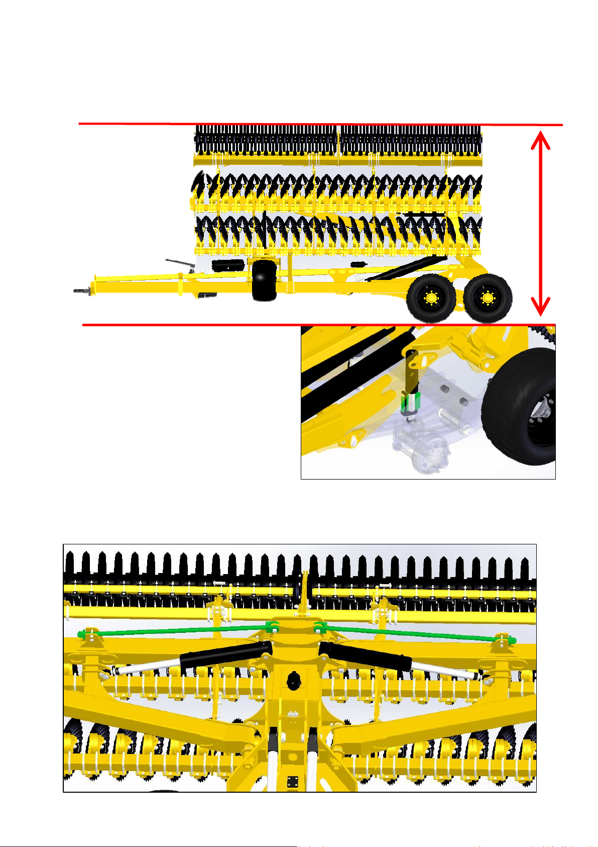
Setting of Transport position
The transport height is adjustable by clips on the
cylinder following:
The height with cage roller will be from 3.80m to
4.00m.
The height with V-sem roller will be from 3.90m
to 4.10m
You can set the inclination from left to right side of extension by the cylinders and also by the lower
stop adjustable stem

40
Setting the inclination of DOM
When you are on the end of field, you have to lift up the DOM just enough in order the disc don’t touch
the ground. The deep wheel of control will support the side of DOM in order to help the central frame
when the user turns on the field. If you don’t do that, you can have some damage on the Security
spring or other elements of DOM.

41
4.5.2.1. Adjusting the side deflectors on mounted and semimounted Disc-O-Mulch GOLD machines
The left-hand side deflector may be adjusted to limit the spraying of soil from the first row of disks
during work.
The following procedure must be followed:
- Loosen the lock nuts and screws "A"
- Adjust the deflector to the required position
- Retighten the screws and the lock nuts
4.5.2.2. Adjusting the border spreading disk
Mounting the Disc-O-Mulch SILVER:
Adjustments may be made to the border spreading disk to avoid a ridge forming during work.
The following procedure must be followed:
- Loosen the 3 screws "D" and the
lock nut
- Adjust the border spreading disk using
the oblong hole.
- Retighten the screws and the lock nut.
Mounting the Disc-O-Mulch GOLD:
- Retighten the 3 screws "E"
- Adjust the border spreading disk using
the oblong holes.
- Retighten the screws

42
Assembling the Disc-O-Mulch GOLD with a
folding roller:
- The gap of the deflector can be adjusted.
- The work intensity of the disk can also
be adjusted.
4.5.3. OPERATING RECOMMENDATIONS
Problems Point to be checked Solutions
The Disc-O-Mulch is
veering Working depth Check that the working
to one side to the other depth is the same for
both rows of disks.
The Disc-O-Mulch is not
working The tractor's top-links
at the same depth The tractor's top-links must be adjusted
on the right and the left to the same length
A ridge forms between Adjust the border
two passages of the Disc-O-Mulch spreading disk.
border spreading disk
Working depth Reduce the working depth
The disks are of the Disc-O-Mulch
jammed
Wear on the disks Replace the disks
Adjustment of the
Irregular working depth
extensions Adjust the extensions

43
4.6. SERVICING - MAINTENANCE
Comply with the safety instructions regarding servicing and maintenance. Your machine has been
designed and built for maximum yield, profitability and comfort under many different usage conditions.
Your machine has been checked at the factory and by your dealer before its delivery to ensure that
you receive a machine in perfect condition. To maintain it in good working condition, it is important that
servicing and maintenance operations are performed at the recommended frequency.
In order to ensure that your machine always operates correctly and to obtain an optimum
performance, you must clean and maintain it at regular intervals. The hydraulic components and
bearings must not be cleaned with a high-pressure washer or directly hosed down. The units, screwed
connectors and bearings are not watertight to VERY high pressure cleaning.
4.6.1. Servicing frequency
The servicing frequency is determined by various factors. Different usage conditions, the weather,
driving and working speeds, dust and the type of soil, etc. affect the frequency, and the lubrication and
maintenance products used also determine the time until the next servicing work is required.
The servicing frequency indicated is therefore only to be used as a reference. If you deviate from the
normal conditions of use, you must adapt the frequency at which this maintenance and servicing is
carried out to suit the conditions:
1/ After the first 10 hours of use:
- Check the tightness of the nuts and screws
- Check the hydraulic system (tightness and sealing)
- Check the tightness of the wheels
- Perform a complete diagnosis of the machine to ensure that there are no elements
causing problems.
- Clean the soil off the machine
2/ Every 50 hours of use
- Check the tightness of the nuts and screws
- Check the hydraulic system (tightness and sealing)
- Check the tightness of the wheels
- Perform a complete diagnosis of the machine to ensure that there are no elements
causing problems.
- Lubricate the joints with greasers
- Clean the soil off the machine
4.6.2. Storage
If the machine is not going to be used for an extended period:
• Store the machine under a roof if possible.
• Disconnect the electrical control devices and store them in a dry place.
• Protect the machine against rust. Only spray with oils that are easily biodegradable, e.g. rape
oil.
• Unload the wheels.
• Protect the hydraulic cylinder piston rods against corrosion.

44
Do not spray plastic and rubber parts with oil or an anti-corrosion agent or these parts may become
fragile and break.
4.6.3. Cleaning
Before folding the machine, the beam under the cylinder must always be cleaned.
A build-up of soil, stones or other obstacles can damage the cylinder.
Failure to comply with this instruction will invalidate the warranty.
4.6.4. Lubrication
Lubricating the machine:
The machine must be lubricated regularly and after each pressure wash.
This keeps the machine in good working order and reduces the costs of repairs and downtime.
Hygiene:
Using lubricants and mineral products in line with the recommendations does not present any health
risks. However, avoid prolonged contact with the skin or inhaling the vapours.
Handling lubricants
WARNING:
Protect yourself from direct contact with oils by wearing gloves or protective cream.
Carefully wash all traces of oil off your skin with soap and hot water. Do not clean your skin with petrol,
diesel or other detergent products.
Oil is toxic. If you swallow oil, consult a doctor immediately.
• Keep lubricants out of reach of children.
• Never store lubricants in open containers or containers that are not labelled.
• Avoid your skin coming into contact with clothes that are soaked in oil. Change clothes when
they are dirty.
• Do not keep cleaning cloths impregnated with oil in your pockets.
• Dispose of shoes impregnated with oil as dangerous waste.
• If oil splashes in your eyes, rinse with clean water and consult a doctor.
• Soak up spilt oil with a binder product and dispose of it.
• Never extinguish fires caused by oil with water. Only use authorised, appropriate extinguishing
products and wear breathing apparatus.
• Waste polluted by oil and used oil must be disposed of in line with current regulations.
Lubricate / grease the machine at the stated frequency.
Carefully clean the lubrication points and the grease pump before lubrication to avoid any dirt getting
into the bearings. Drain contaminated grease out of the bearings and replace with new grease!

45
4.6.5. Greasing
The cage rollers are attached using two self-aligning bearings with greasers.
To ensure that the self-alignment operates correctly, the bearings must be greased at the
start of each new season and then regularly throughout the season.
Use lithium grease reinforced with molybdenum disulphide / Grade NLG12. AGRISEM
INTERNATIONAL may not be held liable if another type of grease is used.
4.6.6. Maintenance
- Hydraulic maintenance
Risk of infection caused by the oil in the hydraulic circuit penetrating the skin under high pressure.
• Operations on the hydraulic circuit must only be performed by a specialised workshop.
• Depressurise the hydraulic circuit completely before carrying out any operations on it.
• Only use appropriate tools to look for leaks.
• Under no circumstances must you try to plug a leak in the hydraulic hoses with your hand or
fingers.
• Liquid leaking under high pressure (hydraulic oil) can penetrate the skin and cause serious
injury.
• In the event of an injury caused by hydraulic oil, consult a doctor immediately. Risk of
infection.
• When connecting hydraulic hoses to the tractor's hydraulic circuit, ensure that the hydraulic
circuits on the tractor and machine are not under pressure.
• Check that the hydraulic hoses are correctly connected.
• Regularly check that the hydraulic hoses and connections are in good condition and are clean.
• Have the hydraulic hoses checked by a specialist at least once a year to ensure that they are
in good condition.
• Replace damaged or worn hydraulic hoses.
• Only use genuine AGRISEM hydraulic hoses.
• Hydraulic hoses must not be used for more than six years, including a possible storage time of
two years maximum. Even under appropriate storage and usage conditions in line with
permissible stresses, it is completely normal for hoses and connectors to age, which is why
they have a limited storage time and service life. Nevertheless, the duration of use can be
established in line with empirical values, in particular taking potential risks into account. Other
reference values can be taken into consideration for thermoplastic hoses and pipes.
• Dispose of used oil in accordance with current regulations. If this poses a problem, contact
your oil supplier.
• Keep hydraulic oil out of reach of children.
• Ensure that you do not contaminate the soil or water with hydraulic oil.
After 10 hours of service, and then every 50 hours of service
1. Check that all of the hydraulic circuit's components are sealed.
2. If necessary, tighten screwed connectors.
Before each start-up
1. Visually check the hydraulic hoses for faults.
2. Remove any friction points on hydraulic hoses and tubes.

46
3. Replace damaged or worn hydraulic hoses immediately.
Inspection criteria for hydraulic hoses.
For your own safety, comply with the following inspection criteria.
Replace the hydraulic hoses if you notice any of the following when examining them:
• Deterioration of the outer layer down to the lining (e.g. friction points, cuts, splits).
• Embrittlement of the outer layer (formation of cracks on the outer layer).
• Distortions which do not correspond to the natural shape of the hose or pipe, whether or not
they are under pressure or bent (e.g. separation of the layers, bulges, crushed areas,
bending).
• Areas that are leaking.
• Damaging or distortion of the end fitting (affecting its leaktightness). Slight superficial damage
does not warrant replacement.
• Hose becoming detached from the end fitting.
• Corroded end fitting leading to reduced solidity and function.
• Non-compliance with mounting specifications.
• Exceeding of the 6-year usage period. The following information is vital: the date of
manufacture of the hydraulic hose marked on the end fitting, to which you must add 6 years. If
the date of manufacture indicated on the connector is "2004" the usage period will end in
February 2010. See the "Marking of hydraulic hoses" section for further information.
Fitting and removing hydraulic hoses
When fitting and removing hydraulic hoses, the following instructions must be strictly adhered to:
• Only use genuine AGRISEM hydraulic hoses.
• Pay particular attention to cleanliness.
• You should always fit hydraulic hoses so that in all operating conditions,
They are not subject to traction, apart from that caused by their own weight.
No short lengths are flattened.
There are no external mechanical stresses on the hydraulic hoses.
Avoid hoses rubbing against parts of the machine or against each other by arranging
and attaching them correctly. Protect hydraulic hoses with protective sheaths if
necessary. Cover parts with sharp edges.
The authorised bending radii must not be exceeded.
• If hydraulic hoses are connected to moving parts, measure the length of the hose to ensure
that the total range of movement is no less than the smallest authorised bending radius and/or
that the hose is not subject to traction.
• Attach hydraulic hoses at the places intended for this purpose. Avoid mountings that may
hinder the natural movement of the hose and modifications to its length.
• Hydraulic hoses must not be painted.
Wear ring maintenance:
Some joints on AGRISEM tools have wear rings. These must be changed at the first sign of lateral
play.
Tyre maintenance:
The tyres must always be inflated to a pressure appropriate to their use. The pressure may need to be
changed when moving between the road and the field. The average pressure of all Flexi-Pack tyres is
2.5 bars.

47
4.6.7. Disks
⇒ The disks must be replaced as soon as their diameters reach the values given
below.
Serrated disk
diameter
Ø 460
Ø 510
Ø 560
Ø 610
AGRISEM INTERNATIONAL cannot be held liable if the DISC-O-SEM is used with
disks presenting greater wear than that specified above.
Max. wear
diameter
Ø 400
Ø 440
Ø 480
Ø 520
Mulcher disk diameter Max. wear diameter
Ø 510
Ø 560
Ø 610
Ø 430
Ø 430
Ø 430

48
4.6.8. Lighting system
Always check that your lighting system is in full working order, clean and operational before driving on
the road.
Never set out on the public highway if one of these elements is not in
good condition.
Replacing bulbs:
1. Unscrew the protective glass.
2. Remove the faulty bulb.
3. Fit the replacement bulb (ensure that the voltage and amperage are correct).
4. Refit the protective glass and screw on.
THE LIGHTING IS REMOVABLE AND MUST BE REMOVED BEFORE
WORKING
The lighting board must be removed when using the DISC-O-MULCH in the field.
As the lighting board is designed solely for transport, AGRISEM INTERNATIONAL cannot be held
liable if the lighting board breaks due to being used during work.
Using the DISC-O-MULCH correctly ensures that work on crops takes place safely under optimum
conditions. It is up to the user to decide on and take full responsibility for the risks linked to the
incorrect or inappropriate use of the DISC-O-MULCH.
AGRISEM INTERNATIONAL cannot be held liable under any circumstances for soil damage or a
result that does not meet the user's expectations if the use and safety instructions have not been
complied with.

49

50

51

52
 Loading...