

Page 1
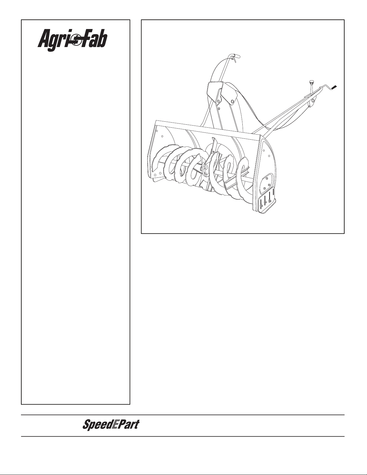
the fastest way to purchase parts
www.speedepart.com
™
Page 2
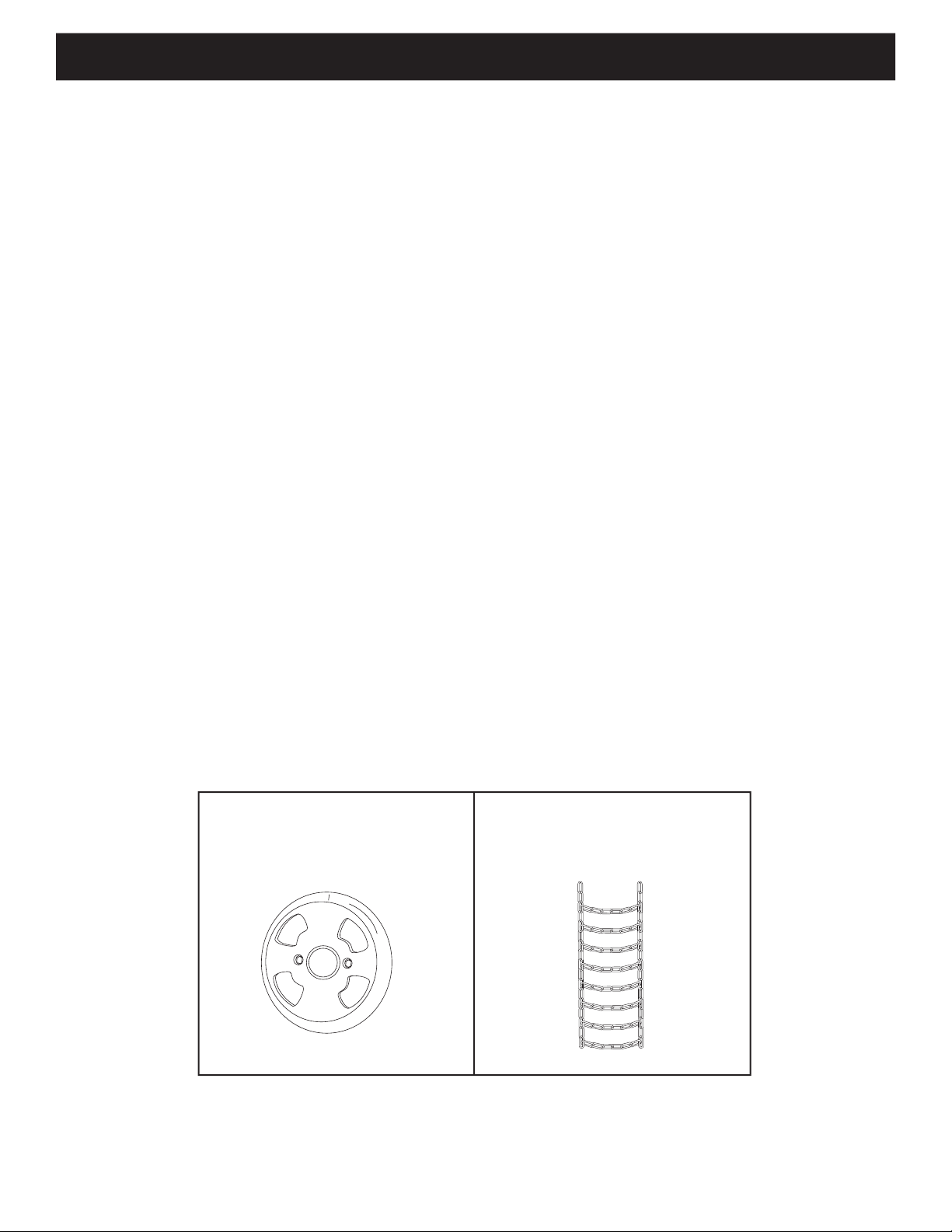
TABLE OF CONTENTS
ACCESSORIES
....................................................................................................................................................................
...................................................................................................................................................................
..........................................................................................................................................................
ASSEMBLY
.......................................................................................................................................................................
........................................................................................................................................
TROUBLESHOOTING
........................................................................................................................................................
.............................................................................................................................
...................................................................................................................................................................
where you purchased your tractor.
WHEEL WEIGHTS TIRE CHAINS
Page 3

SAFETY
Any power equipment can cause injury if operated improperly or if the user does not understand how to operate the equipment.
Read this owner's manual carefully and know how to
Never allow children to operate the equipment.
Never allow adults to operate the equipment without
Keep the area of operation clear of all persons,
Thoroughly inspect the area where the equipment is
to be used and remove all door mats, sleds, boards,
wires and other foreign objects.
Disengage all clutches and shift into neutral before
Do not operate equipment without wearing adequate
winter outer garments.
Wear substantial footwear which will protect feet and
Check fuel before starting the engine. Do not remove
the fuel cap or fi ll the fuel tank while the engine
Make sure the snow thrower height is adjusted to
Do not use the snow thrower without the rear weight
Never make any adjustments while the engine is
Always wear safety glasses or eye shield during
Do not place hands or feet near rotating parts. Keep
Use extreme caution when operating on or crossing
Do not carry passengers.
After striking a foreign object, stop the engine, remove
the wire from the spark plug and then thoroughly
thrower.
If the snow thrower starts to vibrate abnormally, stop
the engine immediately and check for the cause.
Stop the engine whenever you leave the operating
Take all possible precautions when leaving the unit
the parking brake, stop the engine and remove the
When cleaning, repairing or inspecting, make certain
Do not run engine indoors except when transporting
the snow thrower in or out of the building. Open the
Do not clear snow across the face of slopes. Exercise
Never operate the snow thrower without guards,
Never operate the snow thrower near glass
Never direct discharge at bystanders or allow anyone
Never run the snow thrower into material at high
Do not overload the machine capacity by attempting
to clear snow at too fast a rate.
Never operate the machine at high transport speed
Watch for traffi c and stay alert when crossing or
Disengage power to the snow thrower when
transporting or when not in use.
Use only attachments and accessories approved by
the manufacturer of the snow thrower (such as wheel
weights, counter weights, cabs etc.)
Never operate the snow thrower without good visibility
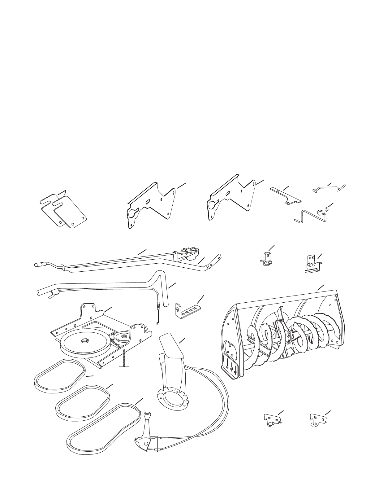
Page 4
E
B
D
G
H
I
K
O
F
X
U
Y
C
W
L
Q
S,T
R
Z
KK
EE
N
CC
BB
AA
NOT SHOWN ACTUAL SIZE
SHOWN ACTUAL SIZE
DD
M
J
JJ
FF
GG
II
V
P
HH
A
LL
NN
MM
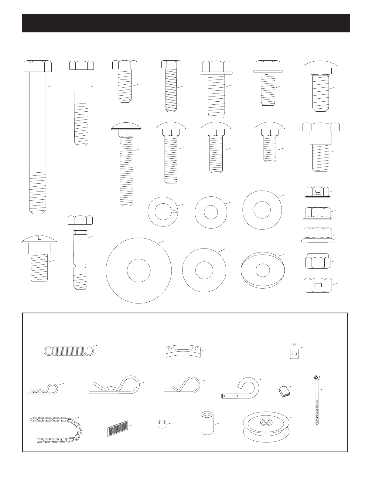
HARDWARE PACKAGE CONTENTS
Page 5
REF. QTY. DESCRIPTION
U 2 Bowed Washer
V 6 Flanged Nut, 1/4"
W 1 Flanged Nut, 5/16"
X 10 Flanged Nut, 3/8"
Y 17 Nylock Nut, 5/16" (2 spare parts)
Z 2 Hex Lock Nut, 3/8"
AA 1 Spring
BB 3 Chute Keeper
CC 1 Trunnion
DD 2 Hairpin Cotter, 5/64"
EE 3 Hairpin Cotter, 1/8"
FF 1 Hairpin Cotter, 3/32"
GG 2 Lock Pin
HH 1 Plastic Cap
II 2 Nylon Tie
JJ 1 Chain, Tensioning
KK 2 Tail Refl ector
LL 1 Small Spacer
MM 1 Large Spacer
NN 1 Pulley
A 1 Hex Bolt, 3/8" x 3-1/4"
B 2 Hex Bolt, 5/16" x 1-3/4"
C 4 Hex Bolt, 5/16" x 3/4"
D 6 Hex Bolt, 1/4" x 1"
E 6 Hex Bolt, 3/8" x 1" (Thread Forming)
F 2 Hex Bolt, 5/16" x 3/4" (Thread Forming)
G 6 Carriage Bolt, 3/8" x 1"
H 2 Carriage Bolt, 5/16" x 1-3/4"
I 2 Carriage Bolt , 5/16" x 1-1/4"
J 4 Carriage Bolt, 5/16" x 1"
K 2 Carriage Bolt, 5/16" x 3/4"
L 4 Shoulder Bolt
M 2 Shoulder Bolt
N 2 Shear Bolt (spare parts)
O 7 Lock Washer, 3/8"
P 7 Washer, 1/4"
Q 6 Washer, 5/16"
R 8 Washer, 1/2"
S 1 Washer, 3/8" (Thin)
T 3 Washer, 3/8"
Page 6
Hardware Package (Stored inside Plastic Keg)
14
1
2
4
5
6
12
9
8
10
20
19
11
17
16
15
18
13
7
3
Page 7
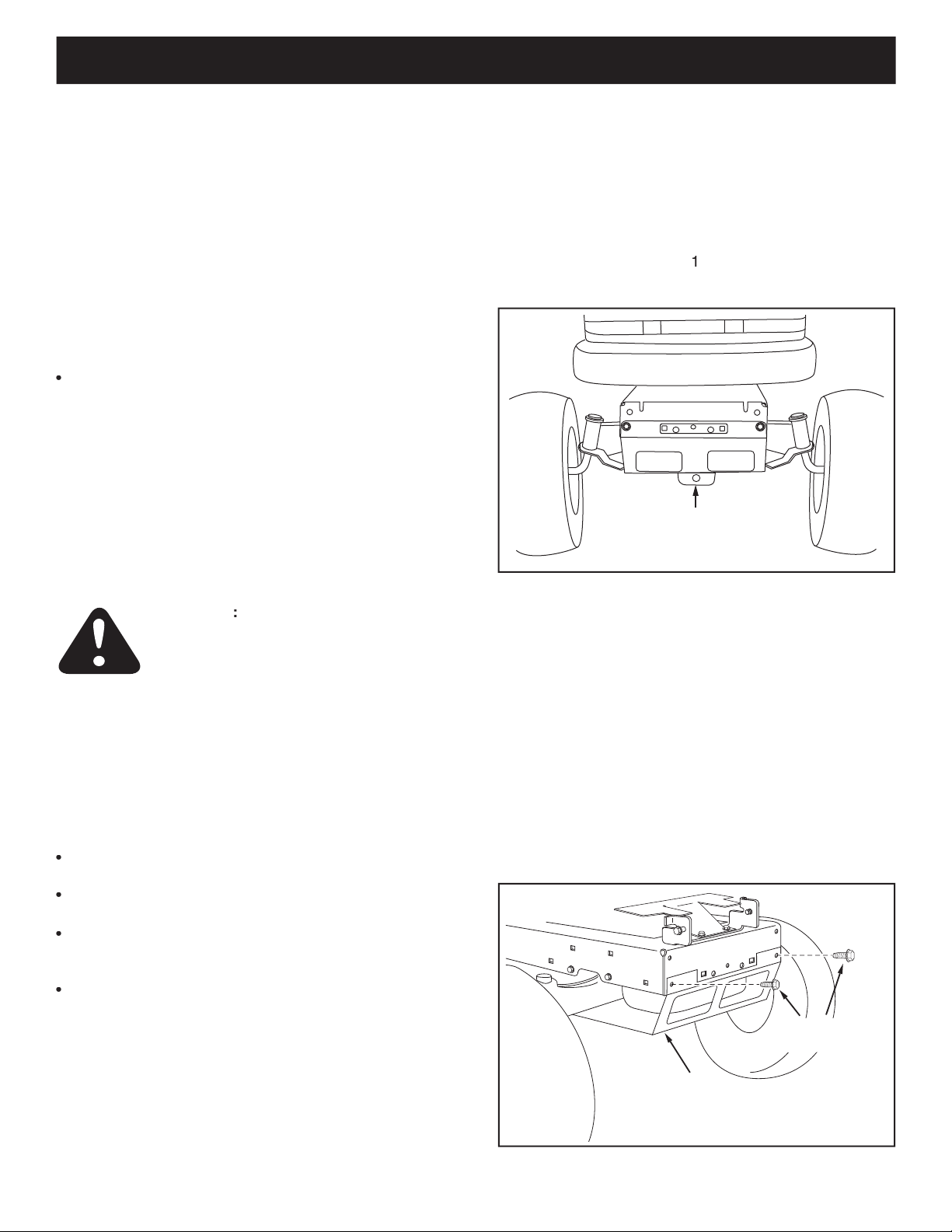
Remove all parts and hardware packages from the
the illustrations on pages 4 and 6.
Not all of the supplied parts and hardware will be
the two
the Service and Adjustments section on page 27.
TOOLS REQUIRED FOR ASSEMBLY
TRACTOR PREPARATION
for specifi c safety instructions.
Allow engine, muffl er and exhaust defl ector to cool
Remove any front or rear attachment which is
Remove the tractor hood. Refer to your tractor owner's
to
from the tractor ignition.
Right hand (R.H.) and left hand (L.H.) side
while seated on the tractor.
REMOVE
FRONT SCREWS
REMOVE
BROWNING SHIELD
MOWER DECK
SUSPENSION
BRACKET
• Remove the browning shield from the front of the
tractor as shown. Hold onto the shield as you remove
the second screw to prevent it from falling.
•
•
under the front of your tractor
f there is a single
the mi
yo
for tractors with dual
ASSEMBLY
Page 8
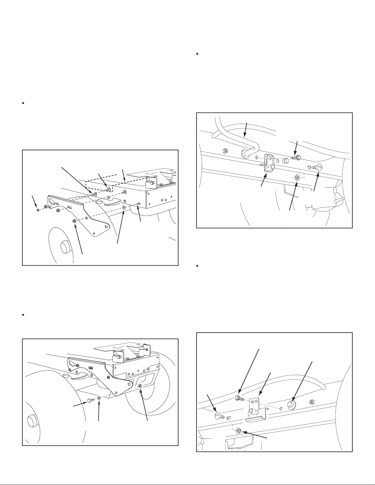
Assemble a shoulder bolt (L) and a 3/8" washer (T) to
the outside of R.H. side plate, securing it with a 3/8"
fl anged nut (X). Repeat for L.H. side plate.
5/16"
NYLOCK
NUT (Y)
5/16" x 1"
CARRIAGE BOLT (J)
ENGINE MOUNTING
PLATE
(4) 1/2" WASHERS (R)
(3) 3/8" FLANGE NUTS (X)
(3) 3/8" x 1"
CARRIAGE
BOLTS (G)
SEE NOTE
3/8" WASHER (T)
SHOULDER
BOLT (L)
3/8" FLANGED
NUT (X)
•
front three holes in the tractor frame using three 3/8"
x 1" carriage bolts (G), three 1/2" washers (R) (see
for L.H. side plate.
Reinstall the browning shield onto the tractor frame
through the plate.
the brake rod on the left side of the tractor frame.
•
Attach the L.H. Hanger Bracket (tube facing out) to the
• Install a round head shoulder bolt (M) into the hole
that is 9-1/2" to the rear of the bolt you just installed.
frame.
5/16" x 3/4" SELF
THREADING BOLT (F)
L.H. HANGER
BRACKET
BRAKE ROD
3/8" FLANGED
NUT (X)
SHOULDER
BOLT (M)
5/16" x 3/4" SELF
THREADING BOLT (F)
R.H. HANGER
BRACKET
RIGHT END OF
BRAKE ROD
3/8" FLANGED
NUT (X)
SHOULDER
BOLT (M)
the tractor frame. Store the bracket and bolt.
Attach the R.H. Hanger Bracket to the hole using a
• Install a round head shoulder bolt (M) into the hole
that is 9-1/2" to the rear of the bolt you just installed.
frame.
Page 9
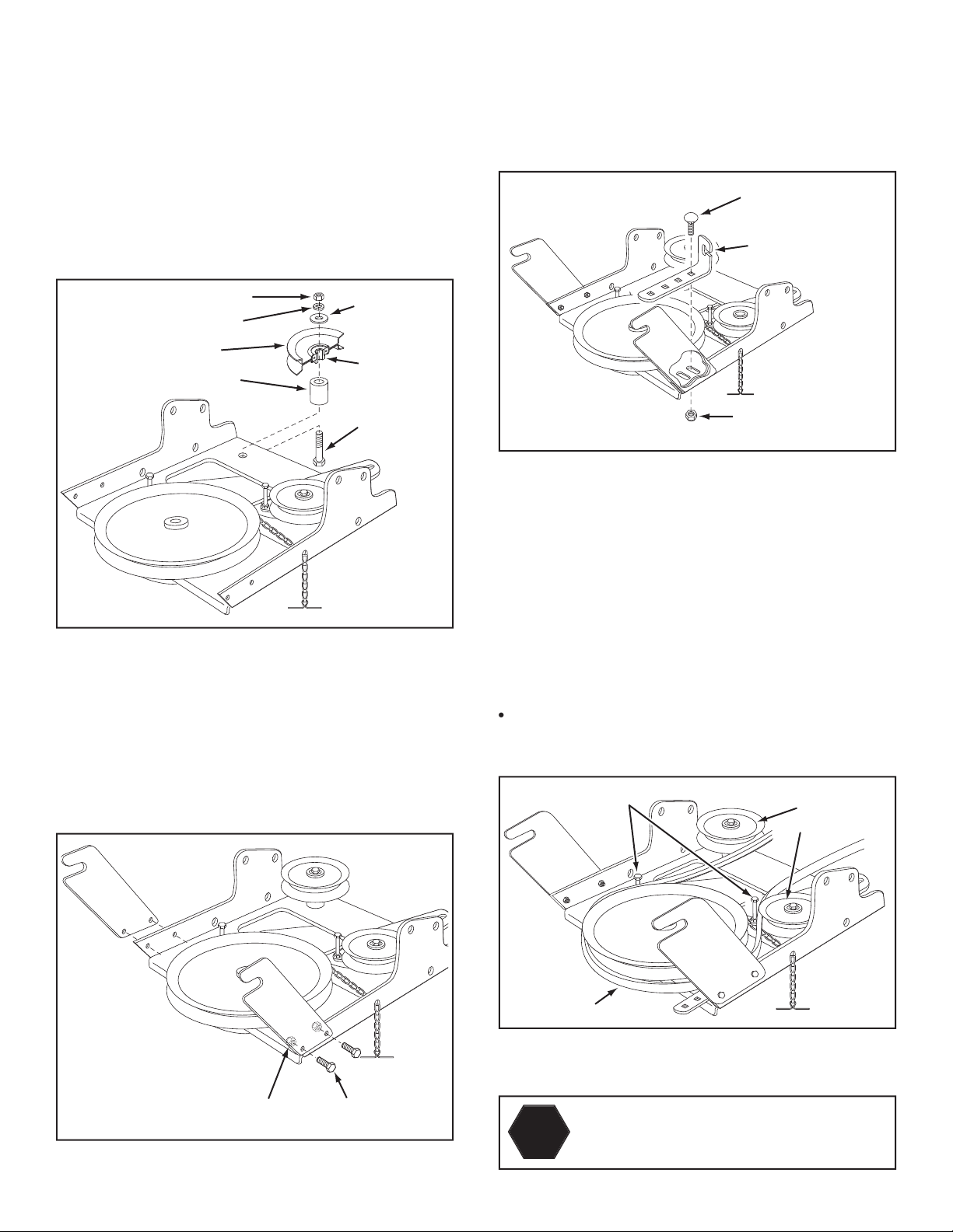
3/8" X 3-1/4"
HEX BOLT
(A)
LARGE SPACER (MM)
PULLEY (NN)
3/8" LOCKWASHER (O)
3/8" HEX LOCK NUT (Z)
3/8"
WASHER (T)
LONG END
OF HUB
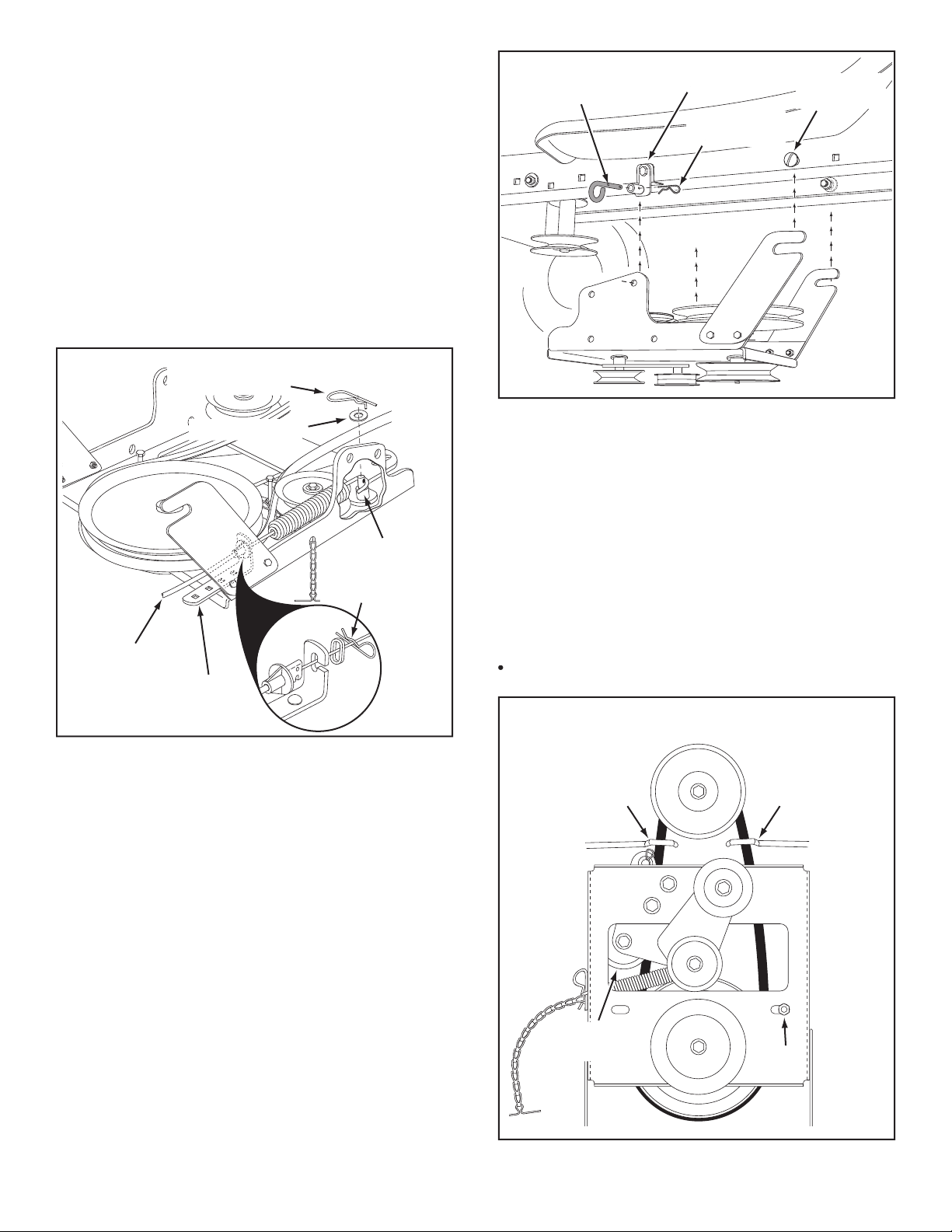
•
Attach the pulley (long end of hub facing down) and
the large spacer (MM) to the hole shown in the clutch/
washer (T), a 3/8" lock washer (O) and a 3/8" hex lock
Attach the cable bracket to the slot shown in the
the front hole of the bracket and in the end of the slot
CABLE
BRACKET
5/16" x 3/4"
CARRIAGE BOLT (K)
5/16" NYLOCK
NUT (Y)
THIS SECTION IS FOR TRACTORS WITH A
HEX BOLTS
(#48138)
DRIVE BELT
FLAT IDLER
PULLEYS
tractor? Using the wrong length belt may
• Two different length drive belts are included with
your snow thrower. Tractors with manual attachment
the 56" drive belt with
#48138
printed on the outside of
the belt.
the other belt.
fl at idler pulley with the fl at side of the belt against the
Loop the belt around the large v-pulley, placing it
5/16" NYLOCK
NUT (Y)
5/16" x 3/4"
HEX BOLT (C)
Attach the two suspension arms to the rear of the
the rear.
STOP
Page 10
Attach the clutch/idler assembly to the tractor frame.
tractor frame. Lift the front of the assembly and attach
PIVOT LOCK PIN (GG)
(use this hole)
SHOULDER
BOLT (M)
1/8" HAIRPIN
COTTER (EE)
L.H. HANGER
BRACKET
•
Assemble the drive belt onto the engine pulley fi rst
assemble the "V" belt outside of
the engine pulley keepers or outside of the keeper bolt
ENGINE
PULLEY
ENGINE
PULLEY
Left Side
of Tractor
ENGINE
PULLEY
KEEPER
ENGINE
PULLEY
KEEPER
KEEPER BOLT
IDLER
PULLEY
5/64" HAIR
COTTER PIN (DD)
1/4" WASHER (P)
SPACER (LL)
TRACTOR'S
CLUTCH CABLE
CABLE
BRACKET
5/64" HAIR
COTTER PIN (DD)
the disengaged (down) position.
•
Attach the tractor's clutch cable to the cable bracket.
•
• Align cable bracket with welded pin and tighten the
Page 11
THIS SECTION IS FOR TRACTORS WITH AN
•
Attach the two suspension arms to the rear of the
the rear.
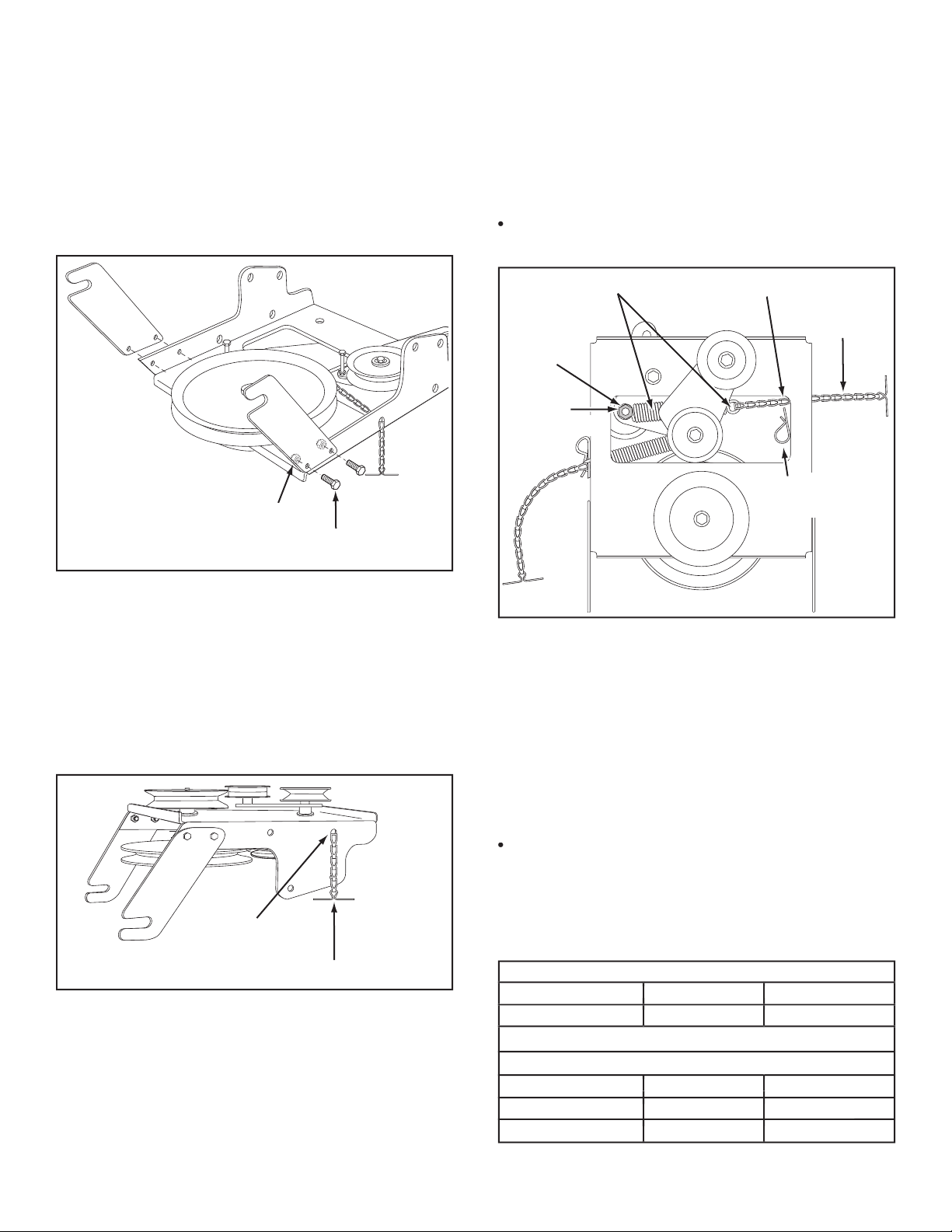
through the end link of the tensioning chain.
•
With the clutch/idler assembly turned upside down,
the spring to pivot freely.
Attach a 3/32" hairpin cotter (FF) to the chain, placing
CHAIN
(L.H. SIDE)
3/32" HAIR
COTTER PIN (FF)
5TH LINK
LEFT
SIDE
3/8" HEX
LOCK NUT (Z)
SPRING
RIGHT
SIDE
ATTACH
SPRING
HERE
•
Turn the clutch/idler assembly upside down and place
the extra tensioning chain (JJ) through the left front
TENSIONING CHAIN (JJ)
LEFT FRONT HOLE
Two different length drive belts are included with
your snow thrower.
the correct drive belt for your type tractor. The part
• Set aside the belt that is not for your tractor to avoid
TRACTOR TYPE DECK SIZE CLUTCH TYPE
(LT) Lawn Tractor 38", 42" Electric
TRACTOR TYPE DECK SIZE CLUTCH TYPE
(LT) Lawn Tractor 48" Electric
(LT) Lawn Tractor 48" Electric
(GT) Garden Tractor 48", 54" Electric
5/16" NYLOCK
NUT (Y)
5/16" x 3/4"
HEX BOLT (C)
Page 12

•
Attach the clutch/idler assembly to the tractor frame.
tractor frame. Lift the front of the assembly and attach
PIVOT LOCK PIN (GG)
(use second hole)
SHOULDER
BOLT (M)
1/8" HAIRPIN
COTTER (EE)
L.H. HANGER
BRACKET
Assemble the drive belt onto the engine pulley fi rst
Place tension on the belt by pulling the left side
tensioning chain (JJ) out as far as the 3/32" hairpin
the chain.
assemble the drive belt around the
1/8" HAIRPIN
COTTER (EE)
ENGINE
PULLEY
ENGINE
PULLEY
KEEPER
BOLT
IDLER
PULLEY
CHAIN (JJ)
(L.H. SIDE)
• Turn the clutch/idler assembly right side up.
fl at idler pulley with the fl at side of the belt against the
Loop the belt around the large v-pulley, placing it
STOP
your tractor? Using the wrong length belt
HEX BOLTS
DRIVE BELT
FLAT IDLER
PULLEY
Page 13

•
front three holes shown in the tractor frame using
three 3/8" x 1" thread forming bolts (E), three 3/8"
the third bolt as a shim between the side plate and
the frame. Tighten all bolts. Repeat for the L.H. side.
If you installed a bolt in the fourth hole in step 21,
•
(3) 3/8" x 1"
THREAD FORMING
BOLTS (E)
5/16" FLANGED
NUT (W)
(SEE NOTE)
(3) 3/8" LOCK
WASHERS (O)
1/2" WASHER (R)
5/16" x 1"
CARRIAGE BOLT (J)
(SEE NOTE)
SUSPENSION
BRACKET
REMOVE BOLTS
IF PRESENT
three holes shown in the tractor frame. Use three 3/8"
x 1" thread forming bolts (E) and 3/8" lock washers (O).
Tighten all bolts and repeat for the L.H. side.
If the bolt inserts freely into the front hole, assemble
(3) 3/8" x 1"
THREAD FORMING
BOLTS (E)
(3) 3/8" LOCK
WASHERS (O)
3/8" FLANGED NUT (X)
(SEE NOTE)
• If a bolt is present in the fourth hole, replace it with a
fastened to inside of frame must remain in place.
FRONT
SUSPENSION
BRACKET
REPLACE BOLT
(IF PRESENT)
REMOVE BOLTS
(IF PRESENT)
f your tractor resembles fi gure 20, go to step 21.
Assemble a shoulder bolt (L) and a 3/8" washer (T) to
the outside of each side plate, securing them with a
3/8" WASHER (T)
SHOULDER
BOLT (L)
3/8" FLANGED
NUT (X)
Page 14

foot rest brackets to the frame.
Attach the L.H. Hanger Bracket (marked "L") to the
•
frame using a 3/8" x 1" carriage bolt (G) and a 3/8"
fl anged nut (X). Bolt head goes on inside of tractor
frame. Repeat for the R.H. side.
Assemble a shoulder bolt (L) and 3/8" fl anged nut (X)
to the R.H. side of the tractor frame, using the fi rst
•
BOLT REMOVED
FROM THIS HOLE
SWAY BAR
BRACKET
SHOULDER BOLT (L)
3/8"
FLANGED
NUT (X)
3/8" x 1"
CARRIAGE
BOLT (G)
3/8" FLANGED
NUT (X)
L.H. HANGER
BRACKET
SUSPENSION ARM
SHOULDER BOLT (L)
3/8"
FLANGED
NUT (X)
R.H. HANGER BRACKET
BOLT REMOVED
FROM THIS HOLE
3/8" x 1"
CARRIAGE
BOLT (G)
3/8" FLANGED
NUT (X)
L.H. HANGER
BRACKET
SUSPENSION ARM
Page 15

This section covers the installation of the Clutch/Idler
tractor.
•
the disengaged (down) position.
•
thrower engagement rod.
Locate the clutch arm (where the mower clutch rod
was connected) underneath the right hand side the
tractor, just to the inside of the suspension arm.
there is an extension
attached to the clutch lever, the
with the mower deck.
to the clutch
•
through the arm. Secure with a 5/64" hairpin cotter
ENGAGEMENT ROD
5/64" HAIRPIN
COTTER (DD)
TRACTOR'S CLUTCH ARM
SUSPENSION ARM
TRUNNION (CC)
REMOVE EXTENSION,
BOLT AND NUT
(IF PRESENT)
•
Attach the two suspension arms to the inside of the
the assembly frame.
5/16" NYLOCK
NUT (Y)
5/16" x 3/4"
HEX BOLT (C)
5/16" WASHER (Q)
your tractor? Using the wrong length belt
HEX BOLTS
DRIVE BELT
FLAT IDLER
PULLEY
• Two different length drive belts are included with
your snow thrower. Tractors with manual attachment
the 55" drive belt with
#46989
printed on the outside
the other belt.
fl at idler pulley with the fl at side of the belt against the
Loop the belt around the large v-pulley, placing it
STOP
Page 16

PIVOT LOCK PIN (GG)
(use second hole)
1/8" HAIRPIN COTTER (EE)
ENGAGEMENT
ROD
•
the idler arm slot. Attach the trunnion (CC) to the slot
•
the tractor frame by removing the washer and nut
that secure the keeper. Attach the new pulley keeper
Some tractors may already be equipped with a
IDLER ARM
5/64" HAIRPIN
COTTER (DD)
TRUNNION (CC)
STOP BOLT
3/8" THIN
WASHER (S)
NEW ENGINE PULLEY KEEPER WITH
ORIGINAL BOLT, NUT AND WASHER
Assemble the short "V" belt onto the engine pulley
assemble the "V" belt around the
ENGINE
PULLEY
KEEPER BOLT
IDLER
PULLEY
ENGINE
PULLEY
KEEPER
Left Side
of Tractor
tied to the engine pulley keeper.
Attach the clutch/idler assembly to the tractor frame
the two shoulder bolts you assembled to the inside
two pivot lock pins (GG) and 1/8" hairpin cotters (EE).
Page 17

•
Assemble the cable bracket to the clutch/idler
•
the disengaged (down) position.
•
Attach the tractor's clutch cable to the cable bracket.
CABLE
BRACKET
5/16" x 3/4"
CARRIAGE BOLT (K)
5/16" NYLOCK
NUT (Y)
42"
DECKS
46"
DECKS
TRACTOR'S
CLUTCH CABLE
5/64" HAIR
COTTER PIN (DD)
1/4" WASHER (P)
SPACER (LL)
5/64" HAIR
COTTER PIN (DD)
Attach the two suspension arms to the rear of the
with the notches to the rear.
5/16" NYLOCK
NUT (Y)
5/16" x 3/4"
HEX BOLT (C)
5/16" WASHER (Q)
HEX BOLTS
DRIVE BELT
FLAT IDLER
PULLEY
• Two different length drive belts are included with
your snow thrower. Tractors with manual attachment
the 55" drive belt with
#46989
printed on the outside
the other belt.
your tractor? Using the wrong length belt
•
fl at idler pulley with the fl at side of the belt against the
Loop the belt around the large v-pulley, placing it
STOP
Page 18

Assemble the short "V" belt onto the engine pulley
assemble the "V" belt around the
the tractor frame by removing the washer and nut
that secure the keeper. Attach the new pulley keeper
Some tractors may already be equipped with a
Attach the clutch/idler assembly to the tractor frame
the two shoulder bolts you assembled to the inside
two pivot lock pins (GG) and 1/8" hairpin cotters (EE).
NEW ENGINE PULLEY KEEPER WITH
ORIGINAL BOLT, NUT AND WASHER
PIVOT LOCK PIN (GG)
(use second hole)
1/8" HAIRPIN COTTER (EE)
ENGINE
PULLEY
KEEPER BOLT
IDLER
PULLEY
ENGINE
PULLEY
KEEPER
Left Side
of Tractor
Page 19

TENSIONING CHAIN (JJ)
LEFT FRONT HOLE
the tensioning chain.
•
the bolt and nut which secure the idler pulley to the
Attach a 3/32" hairpin cotter (FF) to the chain, placing
CHAIN
(L.H. SIDE)
3/32" HAIR
COTTER PIN (FF)
5TH LINK
LEFT
SIDE
3/8" HEX
LOCK NUT (Z)
SPRING
RIGHT
SIDE
ATTACH
SPRING
HERE
Two different length drive belts are included with
your snow thrower.
the correct drive belt for your type tractor. The part
• Set aside the belt that is not for your tractor to avoid
TRACTOR TYPE DECK SIZE CLUTCH TYPE
TRACTOR TYPE DECK SIZE CLUTCH TYPE
(LT) Lawn Tractor 48" Electric
(LT) Lawn Tractor 38", 42", 46" Electric
Attach the two suspension arms to the rear of the
with the notches to the rear.
•
front hole in the clutch/idler assembly and then turn
the assembly upside down.
5/16" NYLOCK
NUT (Y)
5/16" x 3/4"
HEX BOLT (C)
5/16" WASHER (Q)
Page 20

1/8" HAIRPIN
COTTER (EE)
ENGINE
PULLEY
ENGINE
PULLEY
Left Side
of Tractor
KEEPER
BOLT
IDLER
PULLEY
Assemble the drive belt onto the engine pulley and
then onto the large pulley on top of the clutch/idler
the idler pulley and the keeper bolt located beside the
Place tension on the belt by pulling the left side
tensioning chain out as far as the 3/32" hairpin cotter
assemble the "V" belt around the
•
Attach the clutch/idler assembly to the tractor frame
the two shoulder bolts you assembled to the inside
two pivot lock pins (GG) and 1/8" hairpin cotters (EE).
PIVOT LOCK PIN (GG)
(use second hole)
1/8" HAIRPIN COTTER (EE)
HEX BOLTS
DRIVE BELT
FLAT IDLER
PULLEY
STOP
your tractor? Using the wrong length belt
• Turn the clutch/idler assembly right side up.
fl at idler pulley with the fl at side of the belt against the
Loop the belt around the large v-pulley, placing it
Page 21

Place the lift handle into the lift bracket on the right side
LIFT RELEASE
CABLE
HEX NUT
LOCK
WASHER
HEX NUT
CABLE
WIRE
LIFT
ROD
TRIGGER
ASSEMBLY
Be sure the lift release cable's plastic covering
Push the lift handle down into the locked position.
For easier assembly of the lift release cable, tilt the
5/16" NYLOCK NUT (Y)
5/16" x 1-3/4"
HEX BOLT (B)
Tilt the snow thrower back down to the ground.
Assemble the crank rod support tube to the bracket
CHUTE CRANK ROD
CRANK SUPPORT TUBE
TILT CONTROL HANDLE
5/16" x 1-3/4"
CARRIAGE BOLT (H)
BOWED WASHER (U)
5/16" NYLOCK NUT (Y)
TILT
CONTROL
ASSEMBLY
Attach the chute tilt control assembly to the top side
5/16" NYLOCK NUT (Y)
5/16" x 1-1/4"
CARRIAGE BOLT (I)
CRANK ROD
SUPPORT TUBE
DISCHARGE
HOUSING
Page 22

5/16" NYLOCK NUT (Y)
CHUTE CRANK
BRACKET
5/16" WASHER (Q)
CHUTE
CRANK
ROD
ROD
SUPPORT
BRACKET
5/16" x 1"
CARRIAGE BOLT (J)
SPIRAL
ANTI-ROTATION
BRACKET
1/4" FLANGED
LOCK NUT (V)
1/4" FLAT
WASHER (P)
1/4" x 1"
HEX BOLT (D)
PLASTIC CAP (HH)
GREASED
SURFACE
FLANGE
with general purpose grease.
Place the discharge chute (facing forward) onto the
fl ange, aligning it with the holes on the right hand side
Tighten carefully
so
that the nuts are snug but do not dig into the plastic
Place the plastic cap (HH) onto the short end of the
Position the crank rod spiral (see fi gure 51) so that it
Tighten
the nuts.
Check if the crank rod rotates the chute freely. If not,
the chute keepers to the chute fl ange.
Secure the control cables to the crank rod support
tube using a nylon tie (II).
This step is for garden tractors only.
•
Attach the chute crank rod assembly brackets to
the plastic bracket on the left side of the discharge
washers (Q) and 5/16" Nylock nuts (Y).
tighten yet.
STOP BOLT
Page 23

An additional person's help may be required to
Place the tractor and snow thrower on a fl at, level
Remove the Attachment Pin from the snow thrower.
Extend the auger belt out behind the snow thrower,
the large drive pulley and underneath the two idler
Roll the tractor up behind the snow thrower, centering
Raise the rear of the snow thrower by lifting up on
the lift handle until the notches in the mounting plates
To ease the assembly of the auger drive belt, delay
the installation of the attachment pin until you have
The auger belt comes preassembled to the pulleys on
the snow thrower housing. Make sure the belt passes
to pass underneath each side idler pulley. The "V" side
Place the auger belt around the rear pulley and
v-pulleys.
IDLER
PULLEY
AUGER PULLEY
TWIST
1/4 TURN
TWIST
1/4 TURN
IDLER
PULLEY
ATTACHMENT PIN
(After installing auger belt)
1/8" HAIRPIN
COTTER (EE)
SHOULDER
BOLT
MOUNTING
PLATE
SIDE PLATE
IDLER
ARM
REAR
PULLEY
LEFT SIDE
OF
TRACTOR
1/8" HAIRPIN
COTTER (EE)
(Removed from
end of spring)
Page 24

Lift the front of the snow blower to align the holes in
the mounting plates and the side plates. From the left
the holes. Secure it with by reinstalling the 1/8" hairpin
Pull the tensioning chain until the end of the spring is
the end of the spring, securing it on the outside of the
For correct belt tension,
the 1/8" hairpin
To prevent the chain from dragging on the
END OF
SPRING
1/8"
HAIRPIN
COTTER (EE)
LEFT SIDE
OF
TRACTOR
FLAT
PULLEY
REAR REFLECTORS (KK)
If your tractor is not equipped with rear refl ectors,
fender. Place the refl ectors as close to the bottom of
the fender and as far apart as the shape of the fender
will allow.
following checklist to help ensure that you will obtain
the best performance from your snow thrower.
they are routed properly around pulleys and inside all
the raised transport position. (Refer to the Service and
Adjustments section.)
Adjustments section.)
Page 25

OPERATION
Pivots the Upper Chute up or
Rotates the Lower and Upper Chutes to
control the direction of discharge.
Used to lift or lower the snow thrower
to transport or operating position.
Releases the lock which
holds the snow thrower in the transport position
Controls
direction and height of snow discharge.
Replaceable plate that absorbs
wear and impact from contact with ground.
Controls amount of clearance between
the scraper plate and the ground.
Feed snow to the
impeller fan at the center of the housing.
Use the end of assembly checklist to verify that all
Make sure the skid shoes are adjusted to maintain
thrower and the type of surface to be cleared. (Refer
to the Service and Adjustments section.)
Make sure the tractor engine has the correct oil
for winter operation (SAE 5W-30). Refer to tractor
The tractor should be sitting with the engine running
the tractor clutch is engaged.
To stop the snow thrower, disengage the tractor's
towards bystanders or windows. Do not
To control the direction snow is thrown, the discharge
To control the distance snow is thrown, the upper
LIFT HANDLE
LIFT RELEASE TRIGGER
CRANK ROD
CHUTE TILT HANDLE
UPPER CHUTE
LOWER CHUTE
SPIRAL AUGERS, R.H. & L.H.
SKID SHOE
SCRAPER PLATE
Page 26

To raise, push down on the lift handle until the snow
thrower locks in the raised transport position.
To lower, push down slightly on the lift handle and pull
the trigger. With the trigger pulled, slowly lower the
•
Check scraper and shoes for wear X X
Cleaning X
Lubrication Section X
MAINTENANCE SCHEDULE
complete regular service.
After each use
Every season
Before storage
Oil the pivot points of the two idler arms on the clutch/
Apply penetrating oil to the control cables of the
Apply a good grade of spray lubricant to the trigger
thrower without the rear weight attached
to the tractor to provide extra traction and
The scraper plate and skid shoes on the bottom of the
to the spiral auger housing, replace plate and shoes
Before beginning operation, thoroughly inspect the
The spiral auger speed is directly related to engine
to operate the lawn tractor at a slow ground speed
In deep, drifted or banked snow it will be necessary to
the snow. Repeat this method until a path is cleared.
the snow thrower to handle the snow without repeated
In extremely deep snow, raise the snow thrower from
the ground to remove the top layer and drive forward
to the ground. Drive the tractor forward until the snow
If the snow thrower becomes clogged with snow or
jammed with a foreign object, disengage the snow
thrower immediately and shut off the tractor engine.
Discharge snow down wind whenever possible.
To help prevent snow from sticking to the snow thrower,
to the inside surface of the snow thrower housing and
Use tire chains to improve traction.
Use rear wheel weights to improve traction.
Before the fi rst snowfall, remove all stones, sticks and
Overlap each pass slightly to assure complete snow
MAINTENANCE
Page 27

SERVICE AND ADJUSTMENTS
the snow thrower, shut off the engine, remove
the spark plug wire(s), set the parking brake
Disengage the tractor's attachment clutch.
•
Remove the attachment pin.
Lock the snow thrower's lift handle in the down
Release the spring tension from the auger belt idler
Remove the auger drive belt from the clutch/idler
Install new belt over top of large auger drive pulley
turn to seat the "V" of the belt in the groove of each
fi gure 55 on page 23.
Assemble the belt onto the clutch/idler assembly.
The skid shoes are mounted on each side of the spiral
Raise the snow thrower off the ground and place a
Adjust the skid shoes up or down and retighten the
If the lift rod does not lock the snow thrower securely
the lift bracket a few turns and tighten the lower hex
If the lift rod fails to unlock completely to lower the
when the attachment clutch lever on the tractor is
follows. Refer back to fi gure 33 on page 16.
Place the attachment clutch lever in the disengaged
Remove the hairpin cotter from the engagement rod
trunnion and lift the trunnion out of the hole in the idler
Screw the trunnion a few turns towards the front end
Replace the trunnion into the hole in the idler arm and
Check the operation of the snow thrower. If the spiral
the augers stop when the attachment clutch lever is
The spiral augers are secured to the auger shaft with
two shear bolts and nylock nuts. If you hit a foreign
If the augers will not turn, check to see if the shear
the snow thrower. For future use order part number
Page 28

Remove the clutch/idler assembly. (The two hanger
Remove the drive belt from the engine pulley.
If you replaced the engine pulley keeper on a manual
fi gure 39 on page 18.
• If you have a rod operated attachment clutch, remove
the engagement rod from the tractor's clutch arm. See
fi gure 29 on page 15.
• If a rear mounted attachment is to be used, remove
the rear weight tray, leaving the bolts that you installed
If a front mounted attachment is to be used, remove
the side plates from the tractor. Be sure to assemble
•
Remove the snow thrower from the tractor.
Clean the snow thrower thoroughly. Wash off any salt
Any bare metal that has become exposed should be
Store in a dry place.
•
Remove the attachment pin. See fi gure 54 on page
Lock the snow thrower's lift handle in the down
Release the spring tension from the auger belt idler
Remove the auger drive belt from the clutch/idler
Pull the spiral auger housing assembly off of the
tractor.
Clogged discharge chute
Spiral augers don't turn
Snow thrower stalls tractor engine
STORAGE
the snow thrower outdoor temperature before using
Front wheels slide instead of steering
Snow thrower rides up over snow
thrower clutch and clear the auger
decrease ground speed
by lowering skid shoes
2. Pull down on lift handle to
increase weight on front wheels
of skid shoe is lower than the rear
TROUBLESHOOTING
Page 29

Page 30

PARTS
Page 31

REF. PART QTY. DESCRIPTION
NO. NO.
2 64184 1 Housing Assembly
3 618-0616 1 Gear Assembly
4 63579 1 Chute Crank Rod Assembly
5 63768 1 Impeller Assembly
6 24773 1 Scraper Plate
7 703-2734 1 Bracket, Housing Brace
8 703-2735A 1 Bracket, Chute Crank
9 24816 1 Cover, Belt
10 705-5226 1 Chute Reinforcement
11 705-5269 1 Spiral Assembly, L.H. (not shown)
12 705-5270 1 Spiral Assembly, R.H.
13 43182 3 Hex Bolt, 5/16-18 x 3/4" Lg.
14 44950 5 Carriage Bolt, 1/4-20 x 3/4"
15 44917 1 Palnut, 3/8"
16 44326 4 Carriage Bolt, 5/16-18 x 1" Lg.
17 43080 10 Carriage Bolt, 5/16-18 x 3/4" Lg.
18 46703 8 Bolt, Self-Tap 5/16" x 3/4"
19 710-0890A 2 Bolt, Shear 5/16-18 x 1-1/2"
20 43088 11 Washer, 1/4"
21 43064 27 Hex Lock Nut, 5/16-18 Thd.
22 43013 5 Hex Lock Nut, 1/4-20
23 47810 2 Hex Nut, 5/16-18 Nylock
24 715-0114 2 Spiral Pin, 1/4" x 1-1/2" Lg.
25 750-0437 2 Bushing
26 731-1379A 1 Chute Adapter
27 43086 15 Lock Washer, 5/16"
28 736-0188 6 Washer, .76" x 1.49" x .06"
29 711-0469 4 Spacer, .75 ID x 1.25 OD x .5 L
30 43081 18 Washer, 5/16" Std. Wrt.
31 47615 2 Bearing, Flange
32 741-0309 1 Bearing, Ball
33 741-0475 2 Bushing, Plastic 3/8"
34 741-0493A 4 Bearing, Split, 3/4"
35 24279 2 Skid Shoe
36 48015 5 Washer, Nylon
37 784-5618 2 Housing, Bearing
38 24393 1 Bracket, Chute Crank
39 24281 1 Bracket, Idler
40 49933 2 Shoulder Bolt, Round Head
41 65367 1 Hanger Bracket Assembly, L.H.
42 65450 1 Hanger Bracket Assembly, R.H.
43 41576 2 Hex Bolt, 3/8-16 x 1-3/4"
44 44377 1 Hex Bolt, 3/8-24 x 1"
45 784-5594 1 Bracket, Cable
46 746-0929 1 Cable, Chute Control With Clip
47 711-0242 1 Spacer
48 746-0928 1 Cable, Chute Control
49 43082 4 Nut, Hex Lock, 3/8-16
REF. PART QTY. DESCRIPTION
REF. PART QTY. DESCRIPTION
NO. NO.
NO. NO.
51 43343 2 Pin, Hair Cotter #4 (1/8")
52 43350 4 Carriage Bolt, 3/8-16 x 1"
53 24394 1 Bracket, Chute Anti-rotation
54 43003 3 Lock Washer, 3/8"
55 1643-60 1 Plastic Cap
56 64452 1 Hanger Bracket Assembly, R.H.
57 64451 1 Hanger Bracket Assembly, L.H.
58 47043 1 Keeper, Engine Pulley
60 24466 2 Bracket, Down Stop
61 736-0247 1 Washer,
62 47598 6 Hex Lock Nut, 1/4" Flanged
63 731-0921 1 Chute, Upper
64 731-1313C 1 Guide, Cable
65 47044 2 Pulley, V Type 4"
66 47026 1 Pulley, V Type
67 43085 1 Hex Bolt, 5/16-18 x 1-1/2"
68 710-0896 1 Screw, 1/4-14 x 5/8"
69 731-0851A 3 Chute Keeper
70 43661 6 Hex Bolt, 1/4-20 x 1"
71 731-1300C 1 Chute, Lower
72 43070 2 Washer, 3/8"
73 47572 6 Hex Lock Nut, 3/8-16 Flanged
49957 1 Owner's Manual
Page 32

67
36
60
57
61
65
58
62
11
65
58
58
62
63
32
33
Page 33

REF. PART QTY. DESCRIPTION
NO. NO.
1 64637 1 Lift Shaft Assembly
2 710-0865 2 Hex Bolt, 1/2-13 x 1"
3 710-0367 2 Hex Bolt, 5/8-11 x 1-1/2"
4 711-0332 2 Pin, Bracket Lift
5 712-0261 2 Nut, Hex Lock 5/8-11 Thread
6 43262 6 Nut, Hex Lock 1/2-13
8 142 5 Pin, Cotter 1/8" x 3/4"
9 43093 1 Pin, Cotter 1/8" x 1-1/2"
10 R19171616 4 Washer, 17/32" x 1"
11 43350 6 Carriage Bolt, 3/8-16 x 1"
12 741-0192 2 Bearing, Flange With Flats
13 783-0380 2 Link, 15.80" Long
14 783-0381 2 Link, 11.75" Long
15 24476 2 Link, 4.88" Long
16 24311 1 Rod, Spacer
17 47599 2 Hex Bolt, 5/16-18 x 1" (Locking)
18 43086 4 Lock Washer, 5/16"
19 24820 1 Bracket, Lift
20 63773 1 Assembly, Handle Lift Bracket
21 48049 1 Rod, Index Lift
22 47369 1 Pin, Spring 3/16" x 1-3/4"
23 732-0306 1 Spring, Compression
24 R19131316 2 Washer, 13/32" x 13/16"
25 47788 2 Refl ector, Rear
26 43080 1 Carriage Bolt, 5/16-18 x 3/4"
27 43182 2 Hex Bolt, 5/16-18 x 3/4"
28 R19111116 2 Washer, 11/32 x 11/16 x 3/64
30 46954 1 Pin, Attachment
31 43343 1 Pin, Haircotter #4 (1/8")
32 25678 1 Plate, Side (R.H.)
33 25679 1 Plate, Side (L.H.)
34 49916 1 Tube, Lift Handle
35 49912 1 Trigger and Lift Cable Assembly
36 43070 2 Washer, 3/8"
37 710-1233 1 Screw, Oval #10-24 x 1"
38 46446 1 Grip, Handle
39 47027 1 Tube, Crank Rod Support
40 741-0475 2 Bushing, 3/8" Plastic
41 703-2735A 1 Bracket, Chute Crank
REF. PART QTY. DESCRIPTION
NO. NO.
42 720-0201A 1 Knob, Crank
43 44917 1 Palnut, 3/8"
45 63579 1 Assembly, Chute Crank Rod
46 784-5604 1 Handle, Chute Tilt
47 720-0232 1 Knob
48 603-0302 1 Assembly, Chute Tilt Bracket
49 731-1313C 1 Guide, Cable
50 746-0928 1 Cable, Chute Control
51 746-0929 1 Cable, Chute Control with Clip
52 43064 5 Nut, Hex Lock 5/16-18
54 24285 1 Plate, Mounting (L.H.)
55 24284 1 Plate, Mounting (R.H.)
56 43601 1 Washer, 1.59" x 1.032" x .060"
57 46584 1 Nut, Whizlock, 5/16-18
58 R19172410 8 Washer, 1/2"
59 726-0178 3 Tie, Nylon
60 47631 6 Hex Bolt, 3/8-16 x 1" Self Tap
61 43003 6 Lock Washer, 3/8"
62 47572 6 Nut, Flanged Lock 3/8-16
63 47810 8 Nut, Nylock Hex 5/16-18
64 43084 2 Hex Bolt, 5/16-18 x 1-3/4"
65 44326 2 Carriage Bolt, 5/16-18 x 1"
66 44215 2 Carriage Bolt, 5/16-18 x 1-3/4"
67 48106 2 Bolt, Shoulder
68 43682 2 Carriage Bolt, 5/16-18 x 1-1/4"
69 44695 2 Washer, Bowed
Page 34

REF. PART QTY. DESCRIPTION
NO. NO.
2 43064 3 Hex Lock Nut, 5/16-18
3 43083 2 Hex Nut, 5/16-18
4 43086 4 Lock Washer, 5/16"
5 43081 4 Washer, 5/16" Std. Wrt.
6 25727 1 Frame, Clutch and Pulley
7 63904 1 Idler Arm Assembly
8 24286 1 Spacer, Pivot
9 63762 1 Idler Bracket Assembly
10 43015 1 Hex Nut, 3/8-16
11 46981 1 Pulley, V Type 9"
12 43082 8 Nut, Hex Lock, 3/8-16
13 46982 1 Pulley, V Type 5-1/2"
14 738-0680 1 Shaft
15 750-0456 1 Spacer
16 750-0660 1 Spacer
17 43003 6 Lock Washer, 3/8"
18 714-0161 2 Key
19 741-0919 2 Bearing, Ball
20 08253B 1 Housing, Bearing
21 15296A 1 Housing, Open Bearing
22 14088B 1 Spacer, Spindle
23 44377 2 Hex Bolt, 3/8-24 x 1"
24 736-0247 2 Washer
25 43063 3 Hex Bolt, 5/16-18 x 1"
26 46989 1 Belt, V Type Drive (55")
48138 1 Belt, V Type Drive (56")
27 47846 1 Belt, V Type Auger
28 47044 1 Pulley, V Type 4"
29 47025 1 Hex Bolt, 5/16-18 x 3-1/2"
30 43432 1 Hex Bolt, 3/8-16 x 2-1/2"
31 43054 3 Hex Bolt, 3/8-16 x 2"
32 24571 1 Spacer
33 24472 1 Spacer, Pivot
34 43070 8 Washer, 3/8"
35 46959 1 Spring
36 46963 2 Chain
37 43055 1 Pin, Hair Cotter, 3/32"
38 23727 1 Spacer
39 43088 1 Washer, 1/4"
40 43343 2 Pin, Hair Cotter #4 (1/8")
41 47134 2 Pin, Hair Cotter 5/64"
42 711-0198 1 Trunnion
43 46948 1 Rod, Engagement
44 47620 1 Spring
45 47607 1 Spring, Torsion
46 23625 1 Spacer
47 43509 1 Hex Bolt, 3/8-16 x 2-3/4" Lg.
48 47605 1 Washer, Flat 3/8"
49 24558 1 Cable Bracket
50 49870 1 Hex Bolt, 1/4-20 x 2-1/2"
51 43178 2 Hex Nut, 1/4-20
52 43177 1 Lock Washer, 1/4"
53 48883 3 Pulley, Flat 3-5/8"
54 25728 2 Rear Pulley Frame Bracket
55 46938 1 Hex Bolt, 3/8-16 x 3-1/4"
56 25780 1 Spacer
57 47810 6 Hex Nut, 5/16-18 Nylock
58 43182 4 Hex Bolt, 5/16-18 x 3/4"
Page 35

thrower. Refer also to the instructions in your vehicle owners manual.
CAUTION: DO NOT OPERATE YOUR TRACTOR AND SNOW
THROWER ON A SLOPE IN EXCESS OF 10 DEGREES. BE SURE
OF YOUR TRACTOR'S TOWING AND BRAKING CAPABILITIES
BEFORE OPERATING ON A SLOPE. AVOID ANY SUDDEN TURNS OR
MANEUVERS WHILE ON A SLOPE.
A POWER POLE
A CORNER OF A BUILDING
OR A FENCE POST
FOLD ALONG DOTTED LINE, REPRESENTING A 10 DEGREE SLOPE
SIGHT AND HOLD THIS LEVEL WITH A VERTICAL TREE
Page 36

the fastest way to purchase parts
www.speedepart.com
Agri-Fab, Inc.
www.agri-fab.com
© 2003 Agri-Fab, Inc.
 Loading...