

Page 1

Illustrated
2008-01
Parts List
I0807220
531 30 83-24
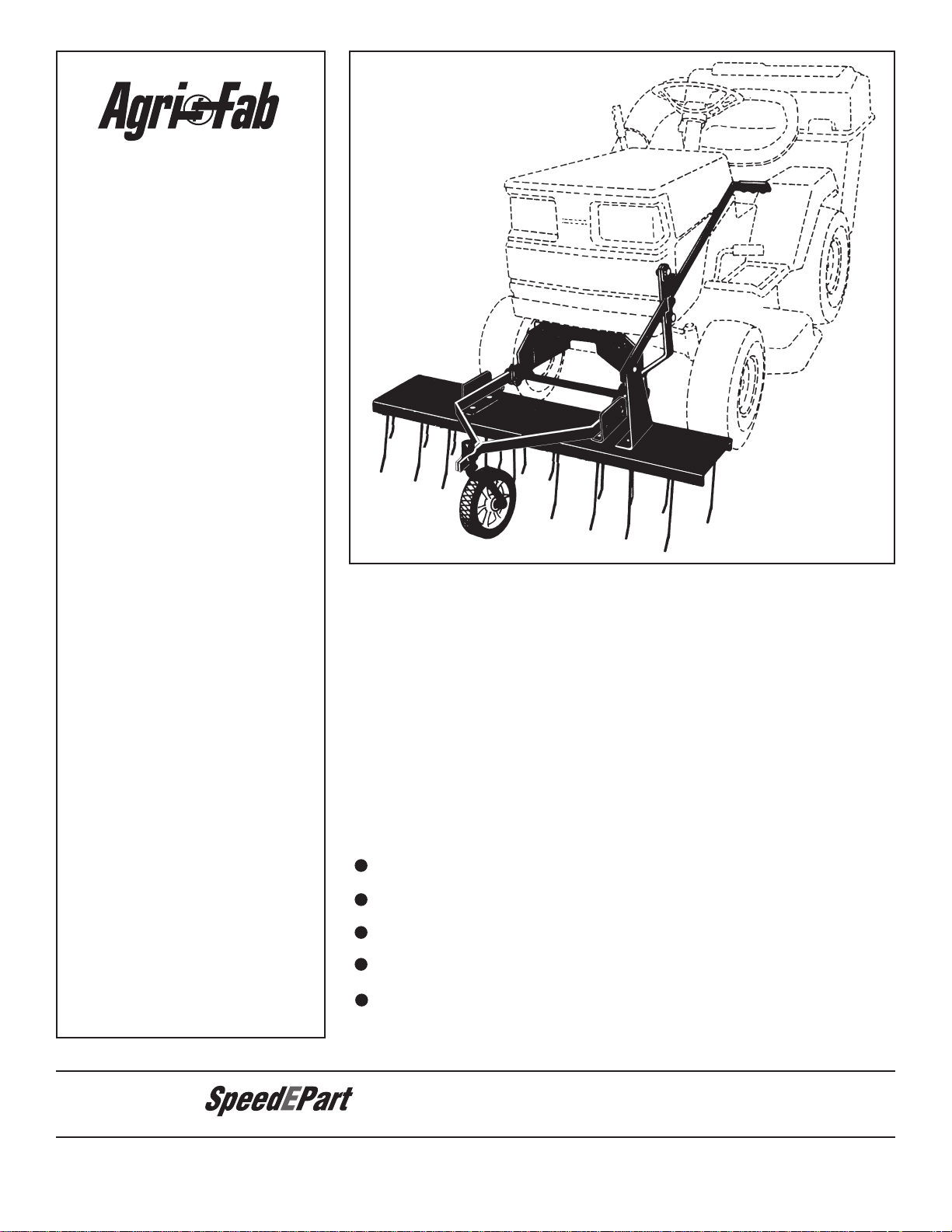
40 Inch Front Mount Dethatcher
(45-0438)
Repair Parts Manual
Page 2
OWNERS
the fastest way to purchase parts
www.speedepart.com
™
MANUAL
Model No.
45-0438
40" FRONT MOUNT
CAUTION:
Read Rules for
Safe Operation
and Instructions
Carefully
TINE DETHATCHER
Safety
Assembly
Operating
Maintenance
Repair Parts
PRINTED IN USA
FORM NO. 40506 (REV. 2/28/07)
Page 3
Any power equipment can cause injury if operated improperly or if the user does not understand how to operate the equipment.
1/2”
9/16”
Exercise caution at all times, when using power equipment.
• Read safety rules in the vehicle owners manual and
know how to operate your equipment, before using the
tine dethatcher.
• Never operate vehicle and tine dethatcher attachment
without wearing substantial footwear, and do not allow
anyone to ride or sit on the tine dethatcher.
• Never allow children to operate the tractor or
dethatcher attachment, and do not allow adults to operate
without proper instructions.
• Eye Protection should be worn when operating the tine
dethatcher.
• Always begin with transmission in rst (low) gear,
and gradually increase speed as conditions permit.
Recommended maximum operating speed is 3 M.P.H.
• Always stop vehicle and lift dethatcher to transport
position before making short turns.
Look for this symbol to point out important safety precautions. It means — Attention!! Become
alert!! Your safety is involved.
• When de-thatching do not drive too close to a creek or
ditch and be alert for holes and other hazards which
could cause you to lose control of the vehicle.
• Before operating vehicle on any grade (hill) refer to the
safety rules in the vehicle owners manual concerning safe
operation on slopes. STAY OFF STEEP SLOPES.
• This equipment is not meant for street or highway use.
Watch for trafc when de-thatching near highways.
• Vehicle and attachments should be stopped and
inspected for damage after striking a foreign object.
• Check all nuts, bolts and screws frequently making sure
they are tight and the equipment is in safe
working condition.
• Follow the maintenance instructions as outlined in this
owners manual.
2
Page 4
1
9
7
10
2
4
6
11
12
3
5
8
15
13
19
24
26
20
21
22
27
16
17
25
18
14
23
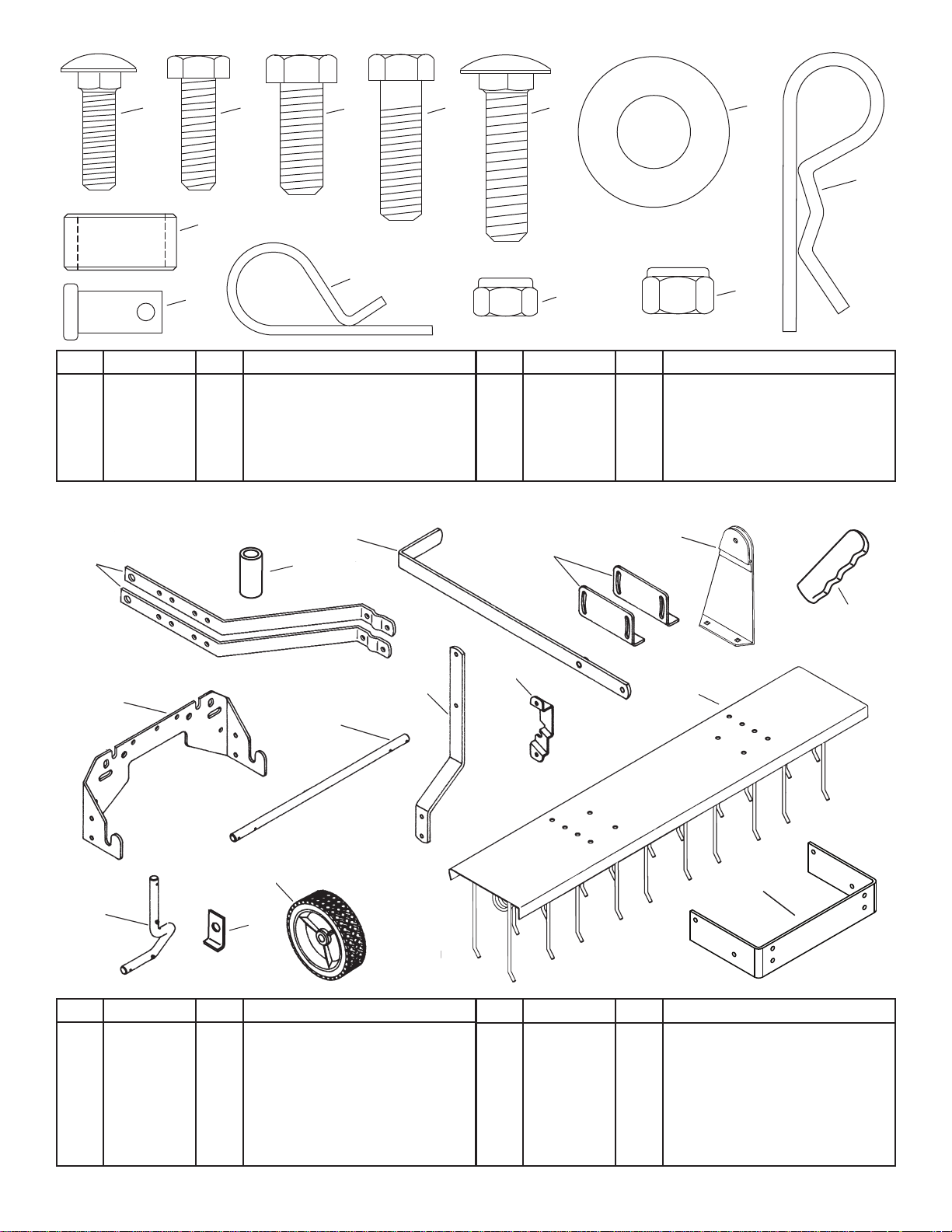
REF PART NO. QTY DESCRIPTION
1 44326 12 Carriage Bolt, 5/16-18 x 1"
2 43063 2 Hex Bolt, 5/16-18 x 1"
3 43001 4 Hex Bolt, 3/8-16 x 1"
4 43087 2 Hex Bolt, 3/8-16 x 1-1/4"
5 43069 4 Carriage Bolt, 3/8-16 x 1-1/2"
6 R19212113 4 Flat Washer, 5/8"
REF PART NO. QTY DESCRIPTION
7 43343 6 Hairpin Cotter, 1/8"
8 46838 4 Spacer, .8" x 1" x .5"
9 44044 1 Clevis Pin, 3/8" x 3/4"
10 43055 1 Hairpin Cotter, 3/32"
11 47810 14 Nylock Nut, 5/16-18
12 HA21362 10 Nylock Nut, 3/8-16
REF PART NO. QTY DESCRIPTION
13 24876 2 Mounting Arm
14 23668 1 Axle Bushing
15 62600 1 Lift Handle
16 23666 2 Angle Mount Bracket
17 62601 1 Lift Handle Bracket
18 43943 1 Plastic Grip
19 26168 1 Hitch Plate
20 26043 1 Mounting Shaft
REF PART NO. QTY DESCRIPTION
21 24043 1 Lift Handle Arm
22 23673 1 Handle Lock Bracket
23 24874 1 Tine Shield
24 44148 1 Axle
25 23676 2 Keeper Plate
26 44213 1 Wheel
27 26044 1 Frame Mount Bracket
3
Page 5

• Remove any front mounted attachments which may
23
1
17
11
TINES POINT
TO FRONT
LEFT END
1
16
11
23
1
13
11
12
4
14
be installed on your tractor.
• Mark all loose parts and save for reassembly.
Stop engine and let mufer cool before
attempting to install dethatcher hitch
brackets.
1
16
1
17
x 1
x 2
11
x 2
2
11
x 2
1
x 4
1
11
x 4
x 4
13
4
x 4
x 2
14
x 1
12
x 2
3
x 2
4
Page 6

APPLY OIL
6
7
26
24
6
7
7
20
4
6
26
6
x 1
x 2
7
x 1
24
x 1
5
7
x 2
x 1
6
20
x 1
7
x 2
5
Page 7

ATTACHING DETHATCHER TO TRACTOR
19
FRONT
3
12
SELF THREADING BOLT
SELF THREADING BOLT
FRONT MOUNTING HOLES
19
27
3
12
• If the front of your tractor has front mounting holes as
shown in gure 7, continue on to gure 8.
• If the front of your tractor DOES NOT have front
mounting holes, go to gure 10.
• Remove two self threading bolts (if present) from
front cross-member of tractor. Assemble bolts through
lower slots in hitch bracket, then reinstall them back
into front crossmember. (Make sure notches at top of
hitch bracket and crossmember are aligned.)
• From behind tractor's front crossmember, insert two
3/8" x 1" hex bolts (3) through holes in crossmember
and through upper slots in hitch bracket. Secure with
two 3/8" nylock hex nuts (12).
7
8
• Go to gure 11 on page 7.
FIGURES 9 AND 10 ARE ONLY FOR TRACTORS WITHOUT FRONT MOUNTING HOLES. FOR
ALL OTHER TRACTORS CONTINUE TO FIGURE 11.
27
x 1
19
x 1
9
3
x 4
12
x 4
6
Page 8

8
12
5
27
• Assemble the frame mount bracket (27) to the tractor
11
1
21
22
19
11
2
21
FRONT
frame using four 3/8" x 1-1/2" carriage bolts (5),
spacers (8) and 3/8" nylock nuts (12). The spacers (8)
go between the tractor frame and the frame mount
bracket.
10
11
21
1
x 2
x 1
22
11
x 2
x 1
12
11
2
x 2
19
x 2
x 1
21
x 1
7
Page 9

• Attach dethatcher to hitch plate by placing mounting
FRONT OF TRACTOR
HITCH
PLATE
SLOT
(LARGE) 1/8"
HAIRPIN COTTER
KEEPER
PLATE
MOUNTING
SHAFT
10
15
17
9
21
22
18
ANGLE BRACKETS
MOUNTING
ARMS
GROUND
TINES
TINE SHIELD
AXLE
BUSHING
shaft into slots at front of hitch plate. Dethatcher
mounting arms go to inside of hitch plate. Assemble
keeper plates onto ends of mounting shaft and secure
with (large) 1/8" hairpin cotters.
18
13
14
15
17
x 1
x 1
10
x 1
x 1
9
x 1
• Raise and lock dethatcher in transport position (see
operation instructions on pages 9 and 10). Move
tractor with front mounted dethatcher onto a level
surface, such as a drive or garage oor. Lower the tine
dethatcher from transport position to rest on the level
surface.
15
• Adjust tine shield until spring tines come in contact
with level surface, keeping front and back tines at
the same height. Tighten carriage bolts securing
mounting arms to angle brackets. See gure 15.
• If you need more adjustment, try moving the axle
bushing up or down between the mounting arms. Be
sure to retighten the bolts securing the bushing.
8
Page 10

CUSTOMER RESPONSIBILITIES
OIL
OIL
LIFT HANDLE
LIFT HANDLE
BRACKET
CLEVIS PIN
LIFT HANDLE
ARM
HANDLE LOCK
BRACKET
SMALL HAIRPIN COTTER
MOUNTING
SHAFT
(LARGE) 1/8"
HAIRPIN COTTER
(LARGE) 1/8"
HAIRPIN
COTTER
SLOT
KEEPER
PLATE
HITCH
PLATE
• Read and follow the maintenance schedule and the maintenance procedures listed in this section.
MAINTENANCE SCHEDULE
Fill in dates as you
complete regular service.
Check for loose fasteners X
Lubrication X
Before each use
Every season
After each use
Before storage
Service Dates
CHECK FOR LOOSE FASTENERS
• Before each use check all nuts and bolts for
tightness. Tighten loose fasteners before using.
LUBRICATION
• Before each use apply a small amount of motor oil
between washer and wheel bearing and between
washer and top of axle bushing. See gure 16.
FIGURE 16
OPERATING TIPS
De-thatching is recommended for early spring, late fall and
prior to fertilizing. It is not recommended to de-thatch with
every mowing of the lawn. The tine dethatcher can be easily
removed for storage (Maintenance/Storage).
• Always start with transmission in rst (low) gear and
gradually increase speed as conditions permit.
• Do not attempt to use dethatcher in eld mowing.
• For best results, use a "criss-cross" pattern on your lawn.
• Vary vehicle speed to determine best speed.
• The front and rear tines should be kept level.
• Stop vehicle and lift dethatcher to transport position
when making sharp turns.
STORAGE
• Always store in a dry area, and coat spring tines with
light oil when not in use.
TO REMOVE DETHATCHER FROM TRACTOR
(Refer to gure 17).
• Lower dethatcher to ground.
• Remove 3/32" (small) hairpin cotter and 3/8" x 3/4"
clevis pin from lift handle. Remove handle from
handle lift bracket.
• Slide lift handle out between lift handle arm and
handle lock bracket.
FIGURE 17
(Refer to gure 18).
• Remove the two outside (large) 1/8" hairpin cotters
from mounting shaft and slide keeper plates off ends
of mounting shaft.
• Lift dethatcher from hitch bracket slots.
• Reassemble hairpin cotters and keeper plates to
mounting shaft for storage.
FIGURE 18
9
Page 11

POCKET
SCREW
DRIVER
AXLE
BUSHING
MOUNTING
ARMS
GROUND
TINE SHIELD
TINES
ANGLE BRACKETS
KNOW YOUR DETHATCHER
NOTCH
STUD
LIFT HANDLE
HANDLE
LOCK
BRACKET
Leveling the dethatcher
• Move tractor with front mounted dethatcher onto a level
surface, such as a drive or garage oor.
• Lower dethatcher from transport position to rest on
level surface.
• Loosen carriage bolts through mounting arms and
angle brackets. (Refer to gure 3 on page 5.)
• Adjust tine shield until spring tines come in contact with
level surface, keeping front and back tines at same
height. Tighten mounting arm carriage bolts on top of
dethatcher shield to lock adjustment. See gure 20.
• If you need more adjustment, try moving the axle
bushing up or down between the mounting arms. Be
sure to retighten the bolts securing the bushing. See
gure 20.
LIFT HANDLE
Raises and lowers
dethatcher.
HANDLE LOCK BRACKET
Locks lift handle in raised
transport position.
HOW TO USE YOUR DETHATCHER
To raise dethatcher to transport position:
• Pull lift handle back so that stud in handle is pulled
past handle lock bracket. Push down and forward on
handle so that stud falls into notch on handle lock
bracket to lock in position. See gure 19.
To lower dethatcher to work position:
• Pull back and up on handle to release stud from notch
in handle lock bracket. Lower by holding up on handle
and pushing forward, allowing stud to pass through
lock bracket. See gure 19.
FIGURE 20
• To replace a spring tine:
a. Use a screw driver to pry the tabs up off of the
spring tine.
b. Remove old spring tine from the tray.
c. Slide a new spring tine under the locking tabs.
Insert a screw driver and bend down the locking
tabs until the ends of the tabs are bent down
even with the surface of the tray. See gure 21.
FIGURE 19
FIGURE 21
10
Page 12

40" TINE DETHATCHER MODEL 45-0438
A
A
23
28
29
25
25
13
13
17
20
22
21
26
24
14
15
19
11
11
11
11
16
16
7
7
7
7
7
7
6
6
6
6
18
9
10
4
3
12
8
5
27
12
12
2
11
1
1
1
1
REF PART NO. QTY DESCRIPTION
1 44326 12 Carriage Bolt, 5/16-18 x 1"
2 43063 2 Hex Bolt, 5/16-18 x 1"
3 43001 4 Hex Bolt, 3/8-16 x 1"
4 43087 2 Hex Bolt, 3/8-16 x 1-1/4"
5 43069 4 Carriage Bolt, 3/8-16 x 1-1/2"
6 R19212113 4 Flat Washer, 5/8"
7 43343 6 Hairpin Cotter, 1/8"
8 46838 4 Spacer, .8" x 1" x .5"
9 44044 1 Clevis Pin, 3/8" x 3/4"
10 43055 1 Hairpin Cotter, 3/32"
11 47810 14 Nylock Nut, 5/16-18
12 HA21362 10 Nylock Nut, 3/8-16
13 24876 2 Mounting Arm
14 23668 1 Axle Bushing
15 62600 1 Lift Handle
REF PART NO. QTY DESCRIPTION
16 23666 2 Angle Mount Bracket
17 62601 1 Lift Handle Bracket
18 43943 1 Plastic Grip
19 26168 1 Hitch Plate
20 26043 1 Mounting Shaft
21 24043 1 Lift Handle Arm
22 23673 1 Handle Lock Bracket
23 24874 1 Tine Shield
24 44148 1 Axle
25 23676 2 Keeper Plate
26 44213 1 Wheel
27 26044 1 Frame Mount Bracket
28 43783 10 Spring Tine
29 47633 2 Wire, Spring Alignment
40506 1 Owners Manual
11
Page 13

© 2006 Agri-Fab, Inc.
the fastest way to purchase parts
www.speedepart.com
REPAIR PARTS
Agri-Fab, Inc.
809 South Hamilton
Sullivan, IL. 61951
217-728-8388
www.agri-fab.com
 Loading...