

Agri-Fab 45-0418 Owner’s Manual
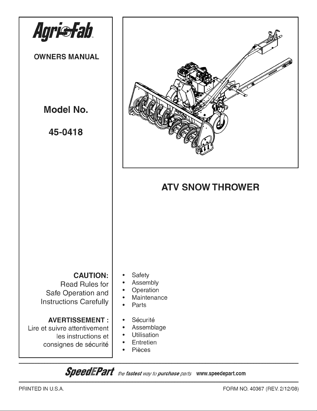
OWNERS MANUAL
IVlodel No.
45-0418
ATV SNOW THROWER
CAUTION:
Read Rules for
Safe Operation and
Instructions Carefully
AVERTISSEMENT •
Lire et suivre attentivement
les instructions et
consignes de securit6
PRINTED IN U.S.A. FORM NO. 40367 (REV. 2/12/08)
o Safety
Assembly
Operation
Maintenance
Parts
Securite
Assemblage
Utilisation
Entretien
Pieces
Anypowerequipmentcancauseinjuryif operatedimproperlyoriftheuserdoesnotunderstandhowto operatethe
equipment.Exercisecautionatalltimes,whenusingpowerequipment.
• Readthisowner'smanualcarefullyandknowhowto
operateyoursnowthrowerandhowto stoptheunit
anddisengagethecontrolsquickly'.
Neverallowchildrentooperatetheequipment.
Neverallowadultsto operatetheequipmentwithout
properinstruction.
Keepthe areaof operationclearof all persons,
especiallysmallchildren,andpets.
Neveroperatethesnowthrowerwithoutgoodvisibility
orlight.
Thoroughlyinspecttheareawheretheequipmentis
tobeusedandremovealldoormats,sleds,boards,
wiresandotherforeignobjects.
Disengageallclutchesandshiftintoneutralbefore
startingengine.
Donotoperateequipmentwithoutwearingadequate
winteroutergarments.
Wearsubstantialfootwearwhichwillprotectfeetand
improvefootingonslipperysurfaces.
NeveroperatetheATVsnowthrowerwithoutattaching
theclipofthetetheredsafetyswitchtoyourclothing.A
riderlessATVwitharunningsnowthrowercouldcause
seriousinjurytoafallenoperatorortoothers.
Checkfuelbeforestartingtheengine.Donotremove
thefuelcapor fill the fueltankwhilethe engineis
runningorhot.Donotfillthefueltankindoors.Gasoline
isanextremelyflammablefuel.
Makesurethesnowthrowerheightisadjustedtoclear
thetypeofsurfaceitwillbeusedon.
Nevermakeany adjustmentswhilethe engineis
running.
Alwayswear safetyglassesor eye shieldduring
operationorwhileperformingadjustmentorrepair.
Donotplacehandsorfeetnearrotatingparts.Keep
clearofthedischargeopeningatalltimes.
Useextremecautionwhenoperatingonor crossing
gravelsurfaces.
Donotcarrypassengers.
Afterstrikinga foreignobject,stopthesnowthrower
andATV,setthebrakeontheATV,removethewire
fromthesparkplugon the snowthrowerandthen
thoroughlyinspectthe snowthrowerfor damage.
Repairanydamagebeforerestartingandoperating
thesnowthrower.
If the snowthrowerstarts to vibrateabnormally',
stopthesnowthrowerandATVimmediately,setthe
brakeontheATV,removethesparkplugonthesnow
throwerandcheckforthecause.Vibrationisgenerally
awarningoftrouble.
Stopthesnowthrowerengineandremovethespark
plugwirewheneveryouleavetheoperatingposition,
beforeuncloggingthesnowthroweror makingany
adjustmentsorinspections.
Takeall possibleprecautionswhenleavingtheunit
unattended.Disengagethe clutchlever,lowerthe
snowthrower,settheparkingbrake,turnofftheATV
andsnowthrowerenginesandremovethekeys.
Whencleaning,repairingor inspecting,makecertain
allmovingpartshavestopped.Disconnectthespark
plugwireandkeepit awayfromtheplugtoprevent
accidentalstarting.
Donotrunengineindoorsexceptwhentransporting
thesnowthrowerinoroutofthebuilding.Openthe
outsidedoors.Exhaustfumesaredangerous.
Donotclearsnowacrossthefaceofslopes.Exercise
extremecautionwhenchangingdirectiononslopes.
Donotattempttoclearsteepslopes.Refertotheslope
guideonpage34ofthismanual.
Neveroperatethesnowthrowerwithoutguards,plates
orothersafetyprotectiondevicesinplace.
Neveroperatethesnowthrowernearglassenclosures,
automobiles,windowwells,dropoffsetc.withoutproper
adjustmentofthesnowthrowerdischargeangle.
Neverdirectdischargeatbystandersorallowanyone
infrontofthesnowthrower.
Neverrun the snowthrowerinto materialat high
speeds.
Donotoverloadthemachinecapacitybyattemptingto
clearsnowattoofastarate.
Neveroperatethemachineat hightransportspeed
onslipperysurfaces.Lookbehindandusecarewhen
backingup.
Watchfor trafficand stay alertwhencrossingor
operatingnearroadways.
Disengagepower to the snow thrower when
transportingorwhennotinuse.
Referto ATVownersmanualbeforeusingother
attachmentsoraccessories.
Neveroperatethesnowthrowerwithoutgoodvisibility
orlight.
This document (or manual) is protected under the U.S. Copyright Laws and the copyright laws of foreign countries, pursuant to the
Universal Copyright Convention and the Berne convention. No part of this document may be reproduced or transmitted in any form or by
any means, electronic or mechanical, including photocopying or recording, or by any information storage or retrieval system, without the
express written permission of Agri-Fab, Inc. Unauthorized uses and/or reproductions of this manual will subject such unauthorized user
to civil and criminal penalties as provided by the United States Copyright Laws.
© 2009 Agri-Fab, Inc.
2
15
\
24
\
REF
1
2
3
4
5
6
7
8
9
10
11
12
13
14
15
12
25
QTY
1
2
1
2
1
1
1
1
1
2
2
1
1
1
1
\
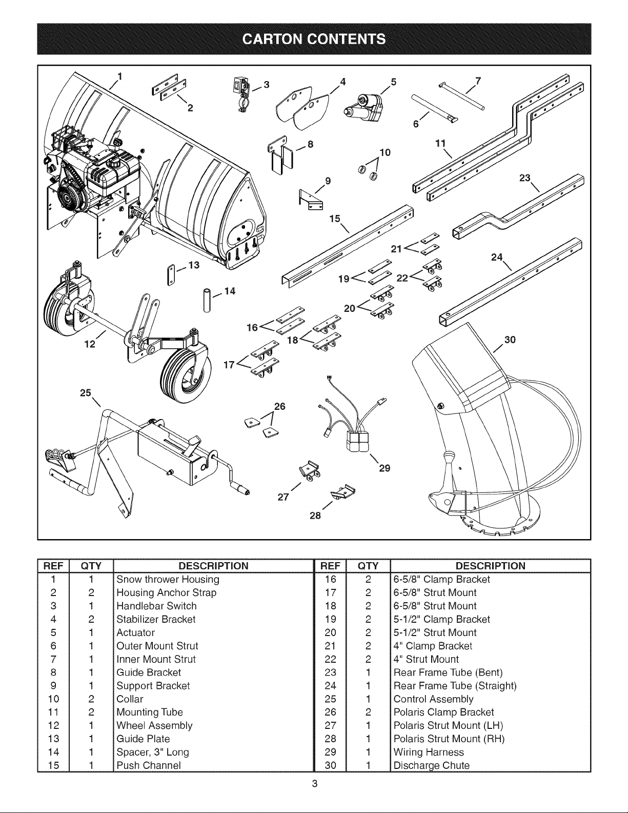
Snow thrower Housing
Housing Anchor Strap
Handlebar Switch
Stabilizer Bracket
Actuator
Outer Mount Strut
Inner Mount Strut
Guide Bracket
Support Bracket
Collar
Mounting Tube
Wheel Assembly
Guide Plate
Spacer, 3" Long
Push Channel
DESCRiPTiON
27 /
28
3
/
REF
16
17
18
19
20
21
22
23
24
25
26
27
28
29
30
QTY
2
2
2
2
2
2
2
1
1
1
2
1
1
1
1
3O
/
\
29
DESCRiPTiON
6-5/8" Clamp Bracket
6-5/8" Strut Mount
6-5/8" Strut Mount
5-1/2" Clamp Bracket
5-1/2" Strut Mount
4" Clamp Bracket
4" Strut Mount
Rear Frame Tube (Bent)
Rear Frame Tube (Straight)
Control Assembly
Polaris Clamp Bracket
Polaris Strut Mount (LH)
Polaris Strut Mount (RH)
Wiring Harness
Discharge Chute
r-T S
O
1
/
2
/
/
7
/
11
/
21
10
S
/
/
/
J 12
J /
/
/
/
/
/
/
/
E
17
13
18
3
/
22
23
____--1/
,-------'-3
-------1
----------1
-------1
-------1
1 I
PARTS NOT SHOWN
28
FULL SiZE
29 3O
26
/
/
I I
I I
I I
25
27
/
REF QTY . DESCRiPTiON = REF QTY . DESCRiPTiON
1 3
2 1
3 4
4 4
5 25
6 2
7 4
8 4
9 2
10 10
11 12
12 1
13 6
14 6
15 18
16 4
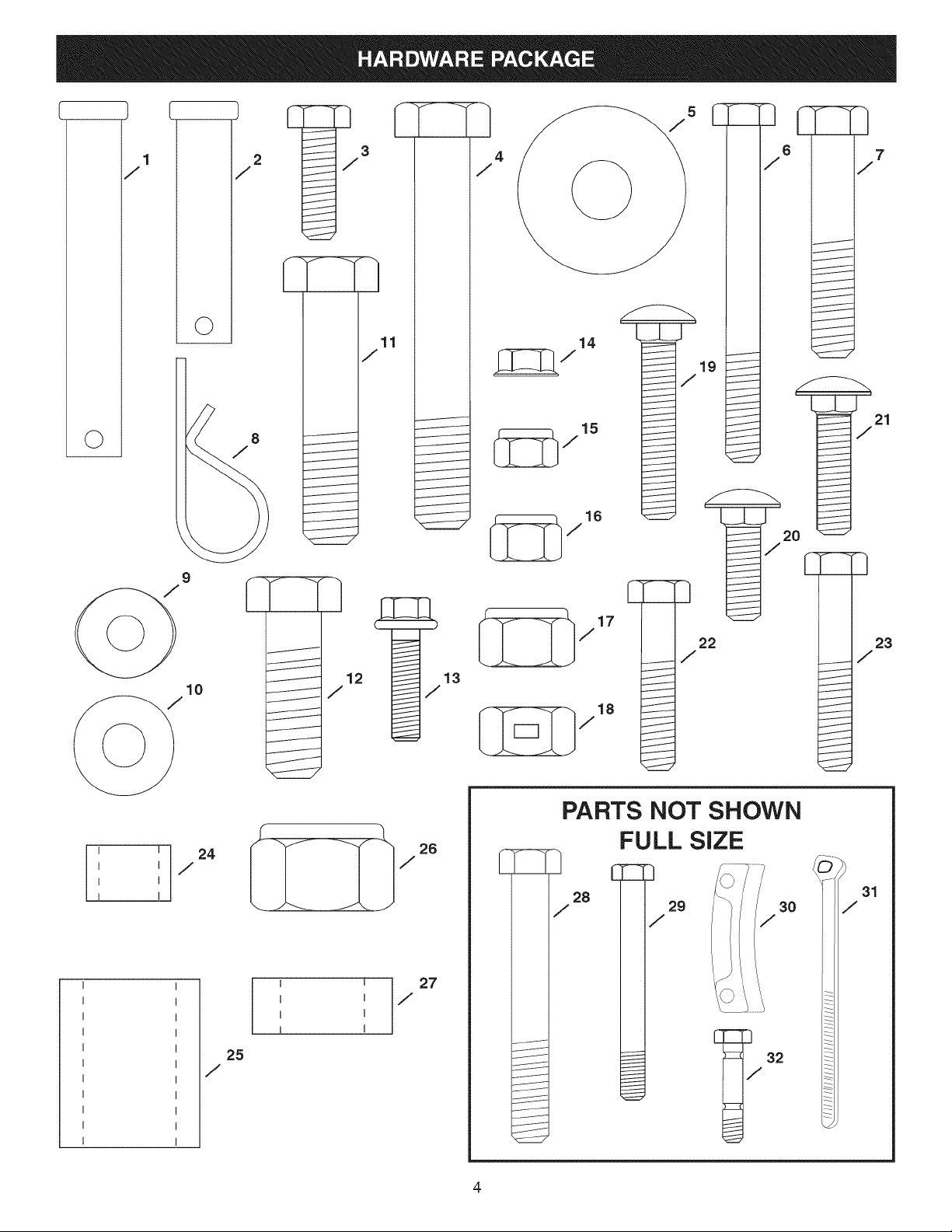
Clevis Pin, 1/2" x 3-1/2"
Clevis Pin, 1/2" x 2"
Hex Bolt, 5/16-18 x 1"
Hex Bolt, 1/2-13 x 3-1/2"
Washer, 1/2" x 1-1/2"
Hex Bolt, 5/16"x 3"
Hex Bolt, 3/8-16 x 2"
Hair Pin
Bowed Washer, 1" x .32"
Washer, 5/16"
Hex Bolt, 1/2-13 x 2-1/4"
Hex Bolt, 1/2-13 x 1-1/2"
Hex Flange Bolt, 1/4-20 x 1"
iFlanged Lock Nut, 1/4-20
iNylock Nut, 5/16-18
iNylock Nut, 3/8-16
17 19
18 2
19 2
20 2
21 2
22 2
23 4
24 2
25 1
26 1
27 4
28 1
29 2
30 3
31 8
32 2
Nylock Nut, 1/2-13
Lock Nut, 1/2-13
Carriage Bolt, 5/16-18 x 1-3/4"
Carriage Bolt, 5/16-18 x 1"
Carriage Bolt, 5/16-18 x 1-1/4"
Hex Bolt, 5/16-18 x 1-1/2"
Hex Bolt, 5/16-18 x 1-3/4"
Spacer, .5" x .75"x .5"
Spacer, .81 "x 1.25" x 1.5"
Nylock Nut, 3/4-10
Spacer .75"x 1.25"x .5"
Hex Bolt, 3/4-10 x 7-1/2"
Hex Bolt, 1/2" x 4-1/2"
Chute Keeper
Nylon Tie
Replacement Shear Bolt
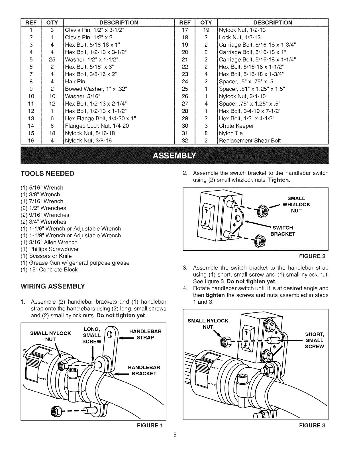
TOOLS NEEDED
(1) 5/16" Wrench
(1) 3/8" Wrench
(!) 7/16" Wrench
(2) 1/2" Wrenches
(2) 9/16" Wrenches
(2) 3/4" Wrenches
(1) 1-1/6" Wrench or Adjustable Wrench
(1) 1-1/8" Wrench or Adjustable Wrench
(1) 3/16" Allen Wrench
(1) Phillips Screwdriver
(1) Scissors or Knife
(1) Grease Gun w/general purpose grease
(1) 15" Concrete Block
WIRING ASSEMBLY
.
Assemble (2) handlebar brackets and (1) handlebar
strap onto the handlebars using (2) long, small screws
and (2) small nylock nuts. Do not tighten yet.
LONG, HANDLEBAR
SMALL NYLOCK SMALL STRAP
NUT SCREW
. Assemble the switch bracket to the handlebar switch
using (2) small whizlock nuts. Tighten.
_ _ WHIZLOCK
_7 SMALL
___tl_ SWITCH
,,,,.,_ BRACKET
FIGURE 2
3. Assemble the switch bracket to the handlebar strap
using (1) short, small screw and (1) small nylock nut.
See figure 3. Do not tighten yet.
4. Rotate handlebar switch until it is at desired angle and
then tighten the screws and nuts assembled in steps
1 and 3.
SMALL NYLOCK
NUT
_ SHORT,
SMALL
SCREW
HANDLEBAR
BRACKET
FIGURE 1 FIGURE 3
5. Secure the relay pack near the battery of the ATV or
other location on the ATV out of harms way.
6. Thread the 3 wire lead from the relay pack forward
through the ATV frame on the same side as the handle
bar switch. Avoid threading wire close to moving parts,
hot parts or pinch points. Use 1 or 2 nylon ties to hold
wire in place.
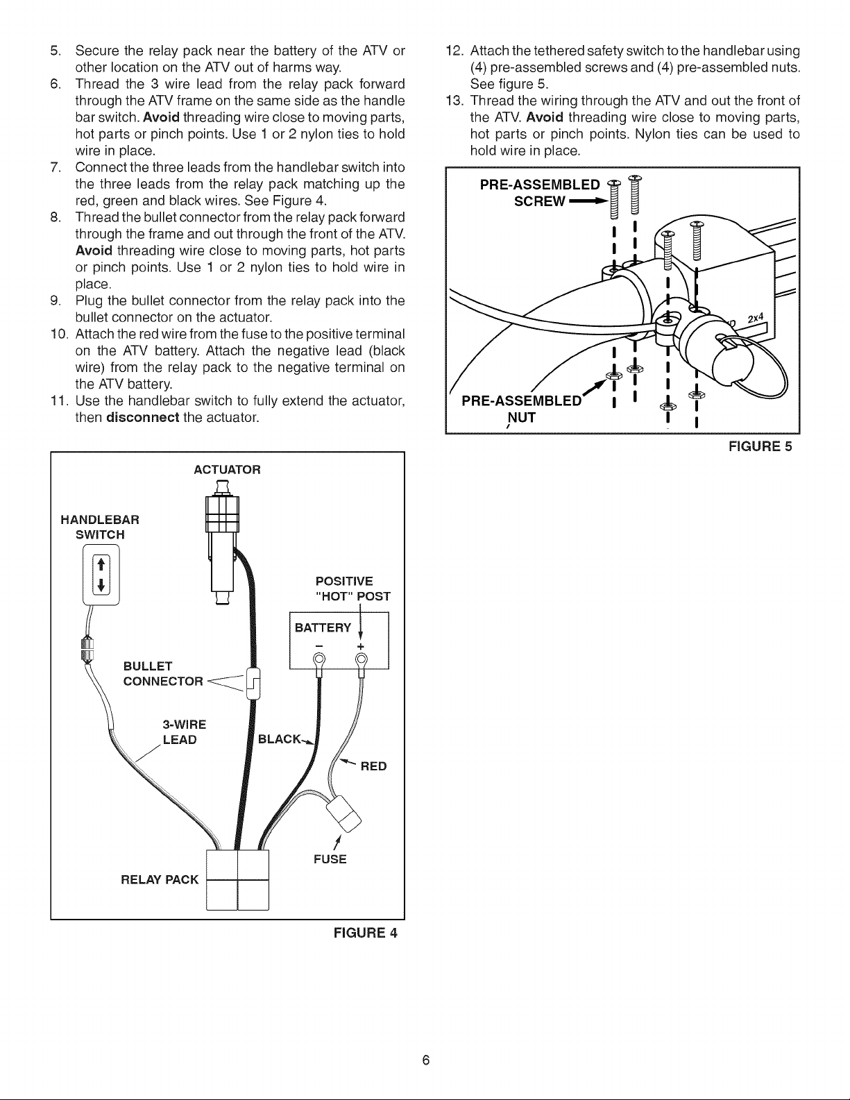
7. Connect the three leads from the handlebar switch into
the three leads from the relay pack matching up the
red, green and black wires. See Figure 4.
8. Thread the bullet connector from the relay pack forward
through the frame and out through the front of the ATV.
Avoid threading wire close to moving parts, hot parts
or pinch points. Use 1 or 2 nylon ties to hold wire in
place.
9. Plug the bullet connector from the relay' pack into the
bullet connector on the actuator.
10. Attach the red wire from the fuse to the positive terminal
on the ATV battery. Attach the negative lead (black
wire) from the relay pack to the negative terminal on
the ATV battery.
11. Use the handlebar switch to fully extend the actuator,
then disconnect the actuator.
ACTUATOR
12. Attach the tethered safety switch to the handlebar using
(4) pre-assembled screws and (4) pre-assembled nuts.
See figure 5.
13. Thread the wiring through the ATV and out the front of
the ATV. Avoid threading wire close to moving parts,
hot parts or pinch points. Nylon ties can be used to
hold wire in place.
PRE-ASSEMBLED '_
!
!
I
I
I
I
FIGURE 5
BULLET
CONNECTOR
3=WIRE
LEAD
RELAY PACK
BATTERY
-- +
RED
/
FUSE
FIGURE 4
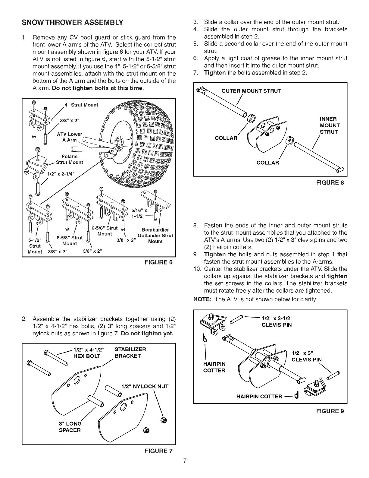
SNOW THROWER ASSEMBLY
.
Remove any CV boot guard or stick guard from the
front lower A arms of the ATV. Select the correct strut
mount assembly shown in figure 6 for your ATV. If your
ATV is not listed in figure 6, start with the 5-1/2" strut
mount assembly. If you use the 4", 5-1/2" or 6-5/8" strut
mount assemblies, attach with the strut mount on the
bottom of the A arm and the bolts on the outside of the
A arm. Do not tighten bolts at this time.
3. Slide a collar over the end of the outer mount strut.
4. Slide the outer mount strut through the brackets
assembled in step 2.
5. Slide a second collar over the end of the outer mount
strut.
6. Apply a light coat of grease to the inner mount strut
and then insert it into the outer mount strut.
7. Tighten the bolts assembled in step 2.
__A 4" Strut Mount
_3/8" x2"
6-5/8" Strut
Strut \ Mount
Mount 3/8" × 2"
3/8" × 2"
' -1/2"--4
6-5/8" Strut _I Bombardier
Mount \ Out(ander Strut
3/8" × 2" Mount
\
FIGURE 6
OUNT STRUT
INNER
MOUNT
STRUT
COLLAR
/
COLLAR
FIGURE 8
8. Fasten the ends of the inner and outer mount struts
to the strut mount assemblies that you attached to the
ATV's A-arms. Use two (2) 1/2" x 3" clevis pins and two
(2) hairpin cotters.
9. Tighten the bolts and nuts assembled in step 1 that
fasten the strut mount assemblies to the A-arms.
10. Center the stabilizer brackets under the ATV. Slide the
collars up against the stabilizer brackets and tighten
the set screws in the collars. The stabilizer brackets
must rotate freely after the collars are tightened.
NOTE: The ATV is not shown below for clarity.
.
Assemble the stabilizer brackets together using (2)
1/2" x 4-1/2" hex bolts, (2) 3" long spacers and 1/2"
nylock nuts as shown in figure 7. Do not tighten yet.
/ 112"x 4-112"
HEX BOLT
STABILIZER
BRACKET
J
I_"NYLOCK NUT
3" LONG
SPACER
FIGURE 7
"------ 112" x 3-112"
CLEVIS PIN
1/2" x 3"
HAIRPIN
CLEVIS PIN
COTTER
HAIRPIN COTTER _
FIGURE 9
7
 Loading...