

Page 1
the fastest way to purchase parts
www.speedepart.com
™
OWNERS MANUAL
MANUEL DU PROPRIÉTAIRE
Model No.
Modèle nº
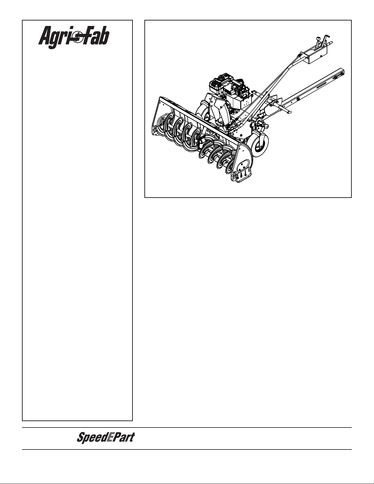
45-0418
ATV SNOW THROWER
SOUFFLEUSE À NEIGE POUR VTT
CAUTION:
Read Rules for
Safe Operation and
Instructions Carefully
AVERTISSEMENT :
Lire et suivre attentivement
les instructions et
consignes de sécurité
PRINTED IN U.S.A. FORM NO. 40367 (10/22/07)
Safety•
Assembly•
Operation•
Maintenance•
Parts•
Sécurité•
Assemblage•
Utilisation•
Entretien•
Pièces•
Page 2

SAFETY
Any power equipment can cause injury if operated improperly or if the user does not understand how to operate the
equipment. Exercise caution at all times, when using power equipment.
Read this owner's manual carefully and know how to •
operate your snow thrower and how to stop the unit
and disengage the controls quickly.
Never allow children to operate the equipment.•
Never allow adults to operate the equipment without •
proper instruction.
Keep the area of operation clear of all persons, •
especially small children, and pets.
Never operate the snow thrower without good visibility •
or light.
Thoroughly inspect the area where the equipment is •
to be used and remove all door mats, sleds, boards,
wires and other foreign objects.
Disengage all clutches and shift into neutral before •
starting engine.
Do not operate equipment without wearing adequate •
winter outer garments.
Wear substantial footwear which will protect feet and •
improve footing on slippery surfaces.
Never operate the ATV snow thrower without attaching •
the clip of the tethered safety switch to your clothing. A
riderless ATV with a running snow thrower could cause
serious injury to a fallen operator or to others.
Check fuel before starting the engine. Do not remove •
the fuel cap or ll the fuel tank while the engine is
running or hot. Do not ll the fuel tank indoors. Gasoline
is an extremely ammable fuel.
Make sure the snow thrower height is adjusted to clear •
the type of surface it will be used on.
Never make any adjustments while the engine is •
running.
Always wear safety glasses or eye shield during •
operation or while performing adjustment or repair.
Do not place hands or feet near rotating parts. Keep •
clear of the discharge opening at all times.
Use extreme caution when operating on or crossing •
gravel surfaces.
Do not carry passengers.•
After striking a foreign object, stop the snow thrower •
and ATV, set the brake on the ATV, remove the wire
from the spark plug on the snow thrower and then
thoroughly inspect the snow thrower for damage.
Repair any damage before restarting and operating
the snow thrower.
If the snow thrower starts to vibrate abnormally, •
stop the snow thrower and ATV immediately, set the
brake on the ATV, remove the spark plug on the snow
thrower and check for the cause. Vibration is generally
a warning of trouble.
Stop the snow thrower engine and remove the spark •
plug wire whenever you leave the operating position,
before unclogging the snow thrower or making any
adjustments or inspections.
Take all possible precautions when leaving the unit •
unattended. Disengage the clutch lever, lower the
snow thrower, set the parking brake, turn off the ATV
and snow thrower engines and remove the keys.
When cleaning, repairing or inspecting, make certain •
all moving parts have stopped. Disconnect the spark
plug wire and keep it away from the plug to prevent
accidental starting.
Do not run engine indoors except when transporting •
the snow thrower in or out of the building. Open the
outside doors. Exhaust fumes are dangerous.
Do not clear snow across the face of slopes. Exercise •
extreme caution when changing direction on slopes.
Do not attempt to clear steep slopes. Refer to the slope
guide on page 34 of this manual.
Never operate the snow thrower without guards, plates •
or other safety protection devices in place.
Never operate the snow thrower near glass enclosures, •
automobiles, window wells, drop offs etc. without proper
adjustment of the snow thrower discharge angle.
Never direct discharge at bystanders or allow anyone •
in front of the snow thrower.
Never run the snow thrower into material at high •
speeds.
Do not overload the machine capacity by attempting to •
clear snow at too fast a rate.
Never operate the machine at high transport speed •
on slippery surfaces. Look behind and use care when
backing up.
Watch for trafc and stay alert when crossing or •
operating near roadways.
Disengage power to the snow thrower when •
transporting or when not in use.
Refer to ATV owners manual before using other •
attachments or accessories.
Never operate the snow thrower without good visibility •
or light.
This document (or manual) is protected under the U.S. Copyright Laws and the copyright laws of foreign countries, pursuant to the
Universal Copyright Convention and the Berne convention. No part of this document may be reproduced or transmitted in any form or by
any means, electronic or mechanical, including photocopying or recording, or by any information storage or retrieval system, without the
express written permission of Agri-Fab, Inc. Unauthorized uses and/or reproductions of this manual will subject such unauthorized user
to civil and criminal penalties as provided by the United States Copyright Laws.
© 2007 Agri-Fab, Inc.
2
Page 3
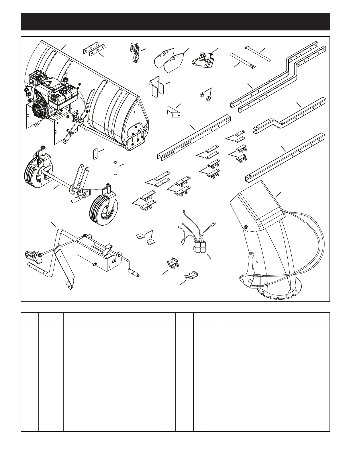
CARTON CONTENTS
1
2
5
4
6
7
10
11
15
23
30
24
9
12
25
29
26
17
18
20
22
16
19
21
28
27
3
8
13
14
REF QTY DESCRIPTION
1 1 Snow thrower Housing
2 2 Housing Anchor Strap
3 1 Handlebar Switch
4 2 Stabilizer Bracket
5 1 Actuator
6 1 Outer Mount Strut
7 1 Inner Mount Strut
8 1 Guide Bracket
9 1 Support Bracket
10 2 Collar
11 2 Mounting Tube
12 1 Wheel Assembly
13 1 Guide Plate
14 1 Spacer, 3" Long
15 1 Push Channel
3
REF QTY DESCRIPTION
16 2 6-5/8" Clamp Bracket
17 2 6-5/8" Strut Mount
18 2 6-5/8" Strut Mount
19 2 5-1/2" Clamp Bracket
20 2 5-1/2" Strut Mount
21 2 4" Clamp Bracket
22 2 4" Strut Mount
23 1 Rear Frame Tube (Bent)
24 1 Rear Frame Tube (Straight)
25 1 Control Assembly
26 2 Polaris Clamp Bracket
27 1 Polaris Strut Mount (LH)
28 1 Polaris Strut Mount (RH)
29 1 Wiring Harness
30 1 Discharge Chute
Page 4
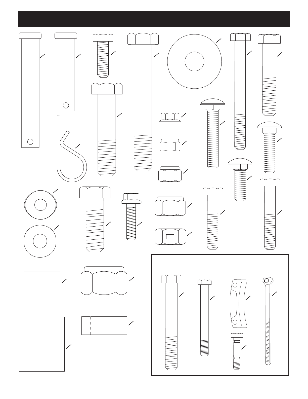
HARDWARE PACKAGE
PARTS NOT SHOWN
FULL SIZE
1 2
3
5
6
7
24
25
13
17
18
12
20
19
4
21
22 23
14
15
16
11
29
28
31
8
9
10
26
27
30
32
4
Page 5
REF QTY DESCRIPTION
OFF
LO
HI
SMALL NYLOCK
NUT
LONG,
SMALL
SCREW
HANDLEBAR
STRAP
HANDLEBAR
BRACKET
SMALL
WHIZLOCK
NUT
SWITCH
BRACKET
OFF
LO
HI
SHORT,
SMALL
SCREW
SMALL NYLOCK
NUT
1 3 Clevis Pin, 1/2" x 3"
2 1 Clevis Pin, 1/2" x 2"
3 4 Hex Bolt, 5/16-18 x 1"
4 4 Hex Bolt, 1/2-13 x 3-1/2"
5 25 Washer, 1/2" x 1-1/2"
6 2 Hex Bolt, 5/16" x 3"
7 4 Hex Bolt, 3/8-16 x 2"
8 4 Hair Pin
9 2 Bowed Washer, 1" x .32"
10 10 Washer, 5/16"
11 12 Hex Bolt, 1/2-13 x 2-1/4"
12 1 Hex Bolt, 1/2-13 x 1-1/2"
13 6 Hex Flange Bolt, 1/4-20 x 1"
14 6 Flanged Lock Nut, 1/4-20
15 18 Nylock Nut, 5/16-18
16 4 Nylock Nut, 3/8-16
REF QTY DESCRIPTION
17 19 Nylock Nut, 1/2-13
18 2 Lock Nut, 1/2-13
19 2 Carriage Bolt, 5/16-18 x 1-3/4"
20 2 Carriage Bolt, 5/16-18 x 1"
21 2 Carriage Bolt, 5/16-18 x 1-1/4"
22 2 Hex Bolt, 5/16-18 x 1-1/2"
23 4 Hex Bolt, 5/16-18 x 1-3/4"
24 2 Spacer, .5" x 1.0" x .59"
25 1 Spacer, .81" x 1.25" x 1.5"
26 1 Nylock Nut, 3/4-10
27 4 Spacer .75" x 1.25" x .5"
28 1 Hex Bolt, 3/4-10 x 7-1/2"
29 2 Hex Bolt, 1/2" x 4-1/2"
30 3 Chute Keeper
31 8 Nylon Tie
32 2 Replacement Shear Bolt
ASSEMBLY
TOOLS NEEDED
(1) 5/16" Wrench
(1) 3/8" Wrench
(1) 7/16" Wrench
(2) 1/2" Wrenches
(2) 9/16" Wrenches
(2) 3/4" Wrenches
(1) 1-1/6" Wrench or Adjustable Wrench
(1) 1-1/8" Wrench or Adjustable Wrench
(1) 3/16" Allen Wrench
(1) Phillips Screwdriver
(1) Scissors or Knife
(1) Grease Gun w/ general purpose grease
(1) 15" Concrete Block
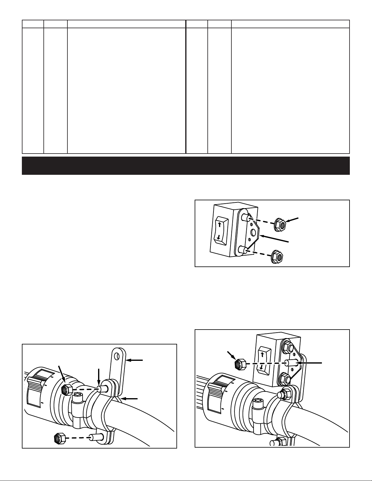
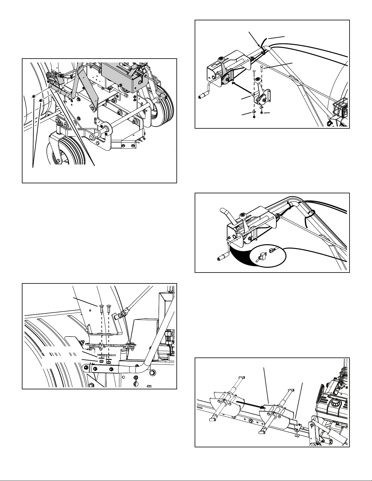
WIRING ASSEMBLY
Assemble (2) handlebar brackets and (1) handlebar 1.
strap onto the handlebars using (2) long, small screws
and (2) small nylock nuts. Do not tighten yet.
Assemble the switch bracket to the handlebar switch 2.
using (2) small whizlock nuts. Tighten.
FIGURE 2
Assemble the switch bracket to the handlebar strap 3.
using (1) short, small screw and (1) small nylock nut.
See gure 3. Do not tighten yet.
Rotate handlebar switch until it is at desired angle and 4.
then tighten the screws and nuts assembled in steps
1 and 3.
FIGURE 1
FIGURE 3
5
Page 6

Secure the relay pack near the battery of the ATV or 5.
2x4
AWD
PRE-ASSEMBLED
SCREW
PRE-ASSEMBLED
NUT
BATTERY
+
POSITIVE
"HOT" POST
BLACK
RED
FUSE
HANDLEBAR
SWITCH
BULLET
CONNECTOR
RELAY PACK
ACTUATOR
3-WIRE
LEAD
other location on the ATV out of harms way.
Thread the 3 wire lead from the relay pack forward 6.
through the ATV frame on the same side as the handle
bar switch. Avoid threading wire close to moving parts,
hot parts or pinch points. Use 1 or 2 nylon ties to hold
wire in place.
Connect the three leads from the handlebar switch into 7.
the three leads from the relay pack matching up the
red, green and black wires. See Figure 4.
Thread the bullet connector from the relay pack forward 8.
through the frame and out through the front of the ATV.
Avoid threading wire close to moving parts, hot parts
or pinch points. Use 1 or 2 nylon ties to hold wire in
place.
Plug the bullet connector from the relay pack into the 9.
bullet connector on the actuator.
Attach the red wire from the fuse to the positive terminal 10.
on the ATV battery. Attach the negative lead (black
wire) from the relay pack to the negative terminal on
the ATV battery.
Use the handlebar switch to fully extend the actuator, 11.
then disconnect the actuator.
Attach the tethered safety switch to the handlebar using 12.
(4) pre-assembled screws and (4) pre-assembled nuts.
See gure 5.
Thread the wiring through the ATV and out the front of 13.
the ATV. Avoid threading wire close to moving parts,
hot parts or pinch points. Nylon ties can be used to
hold wire in place.
FIGURE 5
FIGURE 4
6
Page 7
4" Strut Mount
Polaris
Strut Mount
5-1/2"
Strut
Mount
6-5/8" Strut
Mount
6-5/8" Strut
Mount
Bombardier
Outlander Strut
Mount
5/16" x
1-1/2"
1/2" x 2-1/4"
3/8" x 2"
3/8" x 2"
3/8" x 2"
3/8" x 2"
ATV Lower
A Arm
1/2" x 4-1/2"
HEX BOLT
STABILIZER
BRACKET
1/2" NYLOCK NUT
3" LONG
SPACER
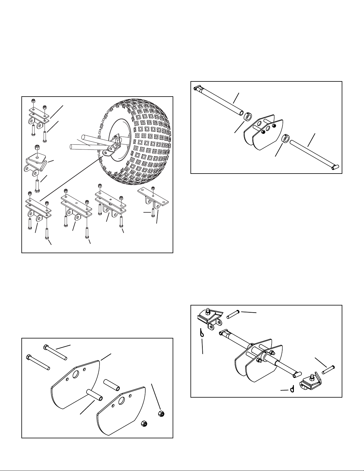
SNOW THROWER ASSEMBLY
OUTER MOUNT STRUT
COLLAR
COLLAR
INNER
MOUNT
STRUT
1/2" x 3"
CLEVIS PIN
HAIRPIN
COTTER
HAIRPIN COTTER
1/2" x 3"
CLEVIS PIN
Remove any CV boot guard or stick guard from the 1.
front lower A arms of the ATV. Select the correct strut
mount assembly shown in gure 6 for your ATV. If your
ATV is not listed in gure 6, start with the 5-1/2" strut
mount assembly. If you use the 4", 5-1/2" or 6-5/8" strut
mount assemblies, attach with the strut mount on the
bottom of the A arm and the bolts on the outside of the
A arm. Do not tighten bolts at this time.
Slide a collar over the end of the outer mount strut.3.
Slide the outer mount strut through the brackets 4.
assembled in step 2.
Slide a second collar over the end of the outer mount 5.
strut.
Apply a light coat of grease to the inner mount strut 6.
and then insert it into the outer mount strut.
Tighten7. the bolts assembled in step 2.
FIGURE 8
Assemble the stabilizer brackets together using (2) 2.
1/2" x 4-1/2" hex bolts, (2) 3" long spacers and 1/2"
nylock nuts as shown in gure 7. Do not tighten yet.
Fasten the ends of the inner and outer mount struts 8.
to the strut mount assemblies that you attached to the
ATV's A-arms. Use two (2) 1/2" x 3" clevis pins and two
(2) hairpin cotters.
Tighten9. the bolts and nuts assembled in step 1 that
FIGURE 6
fasten the strut mount assemblies to the A-arms.
Center the stabilizer brackets under the ATV. Slide the 10.
collars up against the stabilizer brackets and tighten
the set screws in the collars. The stabilizer brackets
must rotate freely after the collars are tightened.
NOTE: The ATV is not shown below for clarity.
FIGURE 9
FIGURE 7
7
Page 8
ANGLE
SLOPES
BACKWARD
1/2" WASHER
1/2" NYLOCK
NUT
1/2" X 2-1/4"
HEX BOLT
HOUSING
ANCHOR
STRAP
MOUNTING
TUBE
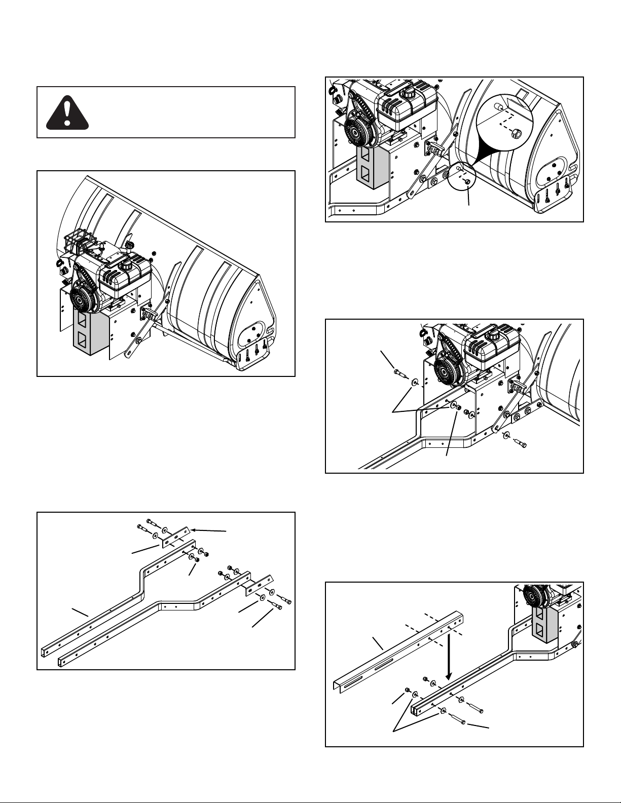
Place a 15" concrete block underneath the snow 11.
1/2" NYLOCK
NUT
PUSH
CHANNEL
1/2" WASHER
1/2" x 3-1/2"
HEX BOLT
1/2" LOCK NUT
1/2" WASHER
1/2" NYLOCK NUT
1/2" X 2-1/4"
HEX BOLT
thrower, beneath the engine. See gure 10.
CAUTION: Use caution while working
on snow thrower when it is propped up on
concrete block.
Attach the front holes of the housing anchor straps to 13.
the weld bolts on the housing using (2) 1/2" lock nuts.
Do not tighten yet.
FIGURE 12
Secure the mounting tubes to the side support straps 14.
using (2) 1/2" x 2-1/4" hex bolts, (4) 1/2" washers (inside
and outside) and (2) 1/2" nylock nuts. Do not tighten yet.
NOTE: Concrete block not shown for clarity.
Attach the housing anchor straps to the 12. outside of the
mounting tubes using (4) 1/2" x 2-1/4" hex bolts, (8)
1/2" washers and (4) 1/2" nylock nuts. Do not tighten
yet.
FIGURE 10
FIGURE 13
Place the push channel over the ends of the mounting 15.
tubes. Line up the holes as shown in the gure below
and secure the push channel using (2) 1/2" x 3-1/2"
hex bolts, (4) 1/2" washers (one on each side) and (2)
1/2" nylock nuts. Do not tighten yet.
FIGURE 11
FIGURE 14
8
Page 9
5/16" NYLOCK NUT
5/16" WASHER
5/16" x 1-3/4"
HEX BOLT
5/16" WASHER
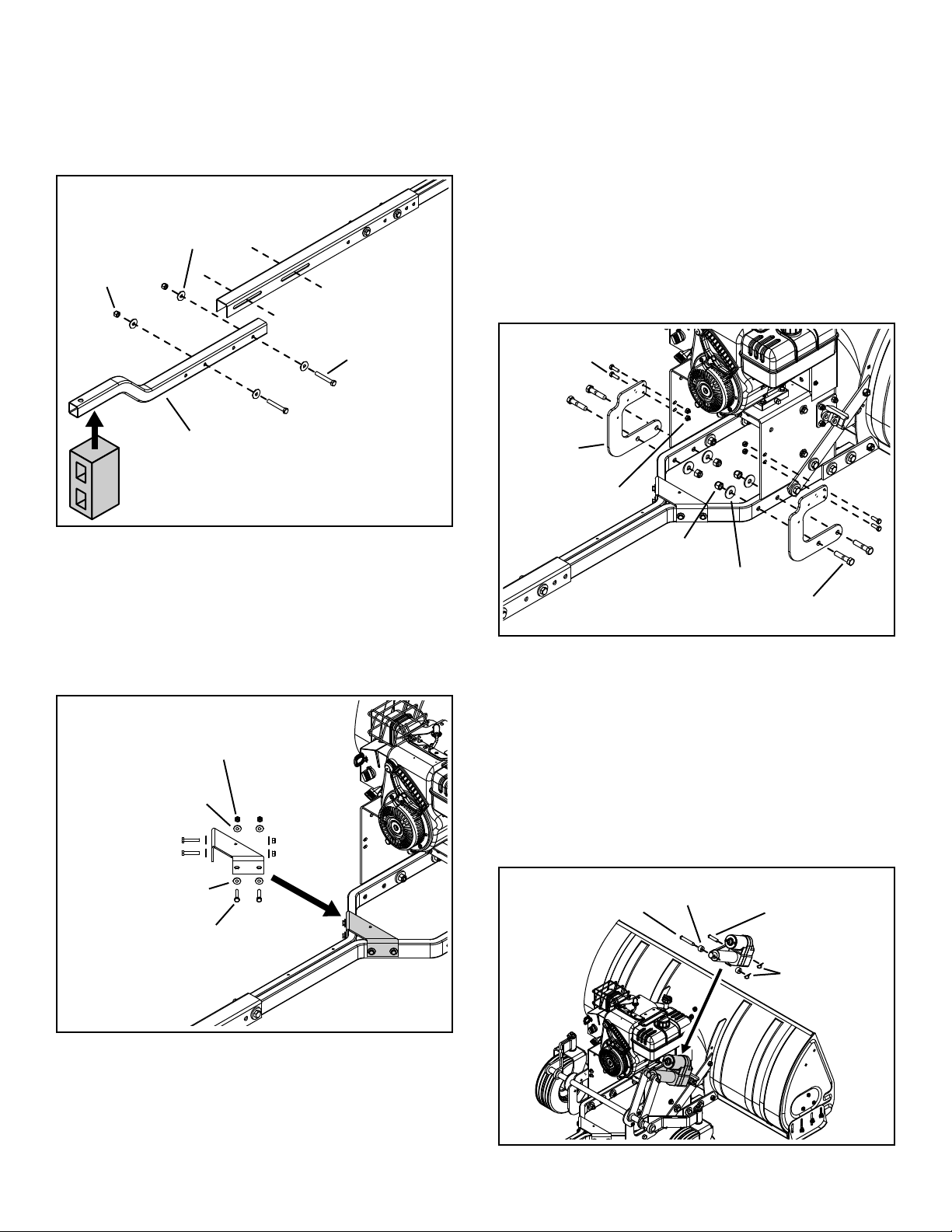
Attach the bent rear frame tube to the push channel 16.
1/2" NYLOCK
NUT
1/2" WASHER
1/2" x 3-1/2"
HEX BOLT
REAR FRAME TUBE
1/2" x 3"
CLEVIS PIN
.5" x 1" x .59"
SPACERS (2)
1/2" x 2"
CLEVIS PIN
HAIRPINS (2)
5/16" x 1"
HEX BOLT
1/2" NYLOCK
NUT
1/2" WASHER
1/2" x 2-1/4"
HEX BOLT
5/16" NYLOCK
NUT
ANCHOR
BRACKET
using (2) 1/2" x 3-1/2" hex bolts, (4) 1/2" washers and
(2) 1/2" nylock nuts. Do not tighten yet.
Remove the concrete block from under the engine 17.
and place it underneath the the end of the rear frame
tube.
Place the wheel assembly behind the engine mounting 19.
base.
Fasten the bottom of the anchor brackets (part of 20.
wheel assembly) to the outside of the mounting tubes
using (4) 1/2" x 2-1/4" hex bolts, (4) 1/2" washers (on
inside of mounting tube) and (4) 1/2" nylock nuts. Do
not tighten yet.
Fasten the tops of the anchor brackets to the engine 21.
mounting base using (4) 5/16" x 1" hex bolts and (4)
5/16" nylock nuts. Do not tighten yet.
Tighten22. all nuts and bolts assembled in steps 12-
14 and 18-21. Do not tighten the nuts and bolts
assembled in steps 15-16 at this time.
NOTE: Complete wheel assembly not shown for clarity.
Attach the support bracket to the mounting tubes using 18.
(4) 5/16" x 1-3/4" hex bolts, (8) 5/16" washers and (4)
5/16" nylock nuts. Tighten.
FIGURE 15
FIGURE 17
NOTE: Before proceeding with next assembly step, make
sure the actuator is fully extended. Refer to step 11 on
page 6 in the Wiring Assembly Section.
Fasten top of actuator to wheel assembly using (1) 23.
1/2" x 3" clevis pin, (2) .5" x 1" x .59" spacers and (1)
hairpin.
Fasten bottom of actuator to actuator bracket using (1) 24.
1/2" x 2" clevis pin and (1) hair pin.
FIGURE 16
FIGURE 18
9
Page 10
GREASE
5/16" x 3"
HEX BOLT
5/16" NYLOCK NUT
GUIDE PLATE
GUIDE
BRACKET
Assemble the guide bracket and guide plate to the 25.
1/2" x 1-1/2" HEX BOLT
1/2" WASHER &
1/2" NYLOCK NUT
1/4" FLANGED
LOCK NUT
1/4" x 1" HEX
FLANGE BOLT
mounting tubes using (2) 5/16" x 3" hex bolts and 5/16"
nylock nuts. Do not tighten yet.
Remove the concrete block from under the rear frame 26.
tube.
FIGURE 19
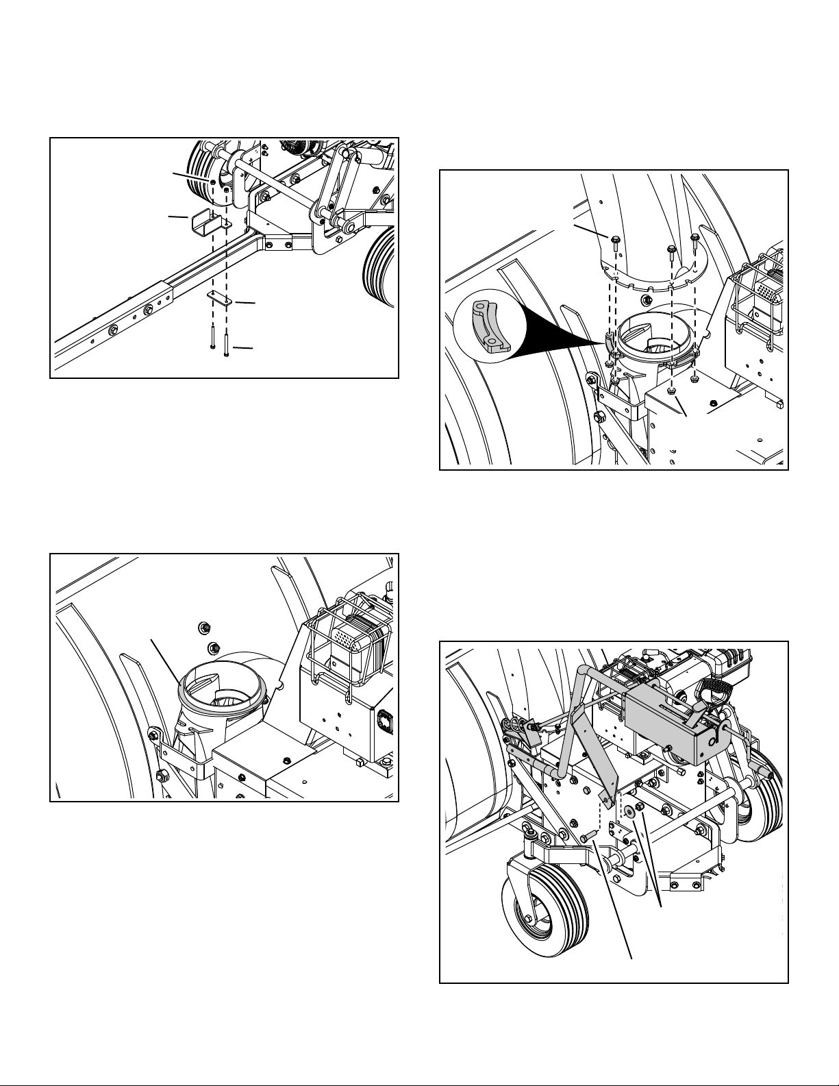
Place the discharge chute (facing forward) onto the 28.
ring. Attach (3) chute keepers (right side up as shown)
to the bottom of the ange using (6) 1/4" x 1" hex ange
bolts and (6) 1/4" anged lock nuts. Tighten carefully
so that the nuts are snug but do not dig into plastic
chute keepers. Grasp the bottom ange and make
sure the chute turns freely.
Lightly coat the top of the ring around the discharge 27.
opening with general purpose grease.
FIGURE 21
Attach the control assembly's support strap to the 29.
engine mounting base using (1) 1/2" x 1-1/2" hex bolt,
1/2" washer (on inside of mounting base) and 1/2"
nylock nut. Do not tighten yet.
FIGURE 20
FIGURE 22
10
Page 11
SECURE CABLES HERE
NYLON TIE
BOWED
WASHER
CHUTE TILT
CONTROL
5/16" NYLOCK
NUT
5/16" x 1-3/4"
CARRIAGE BOLT
5/16" x 1"
CARRIAGE BOLT
5/16" WASHER
5/16" NYLOCK
NUT
STABILIZER BRACKETS
GUIDE BRACKET
5/16" x 1-1/4"
CARRIAGE BOLTS
5/16" NYLOCK NUTS
Attach the control assembly's support tube to the 30.
welded bracket below the discharge chute using (2)
5/16" x 1-1/4" carriage bolts and (2) 5/16" nylock nuts.
Do not tighten yet.
Tighten31. bolts assembled in steps 29 and 30.
FIGURE 23
FIGURE 25
Insert the wire harness into the large hole at the front 38.
of the control box.
Connect the wire harness to the switch.39.
Using nylon ties, secure the wire harness and clutch 40.
cable to the handle assembly to keep them from
interfering with moving parts.
Cut the nylon tie that holds the two chute crank brackets 32.
together.
Attach the chute crank brackets to the discharge 33.
housing using (2) 5/16" x 1" carriage bolts, 5/16"
washers and 5/16" nylock nuts. Do not tighten yet.
Adjust position of chute crank brackets so that spiral 34.
does not rub bottom of discharge chute notches.
Tighten35. bolts and nuts assembled in step 33.
NOTE: Spiral not shown for clarity.
FIGURE 26
Roll the ATV up behind the snow thrower, keeping the 41.
push channel centered between the stabilizer brackets.
Make sure the guide bracket will slide in between
the stabilizer brackets as shown in gure 27. Keep a
minimum clearance of 3"-4" between the front of the
ATV and the snow thrower.
NOTE: ATV not shown below for clarity.
FIGURE 24
Attach the chute tilt control to the control assembly 36.
using (2) 5/16" x 1-3/4" carriage bolts, (2) bowed
washers and (2) 5/16" nylock nuts.
Using a nylon tie, secure the cables from the chute tilt 37.
control to the support tube as shown in gure 25.
Note: Do not secure the chute tilt control cables in locations
other than the one shown.
FIGURE 27
11
Page 12
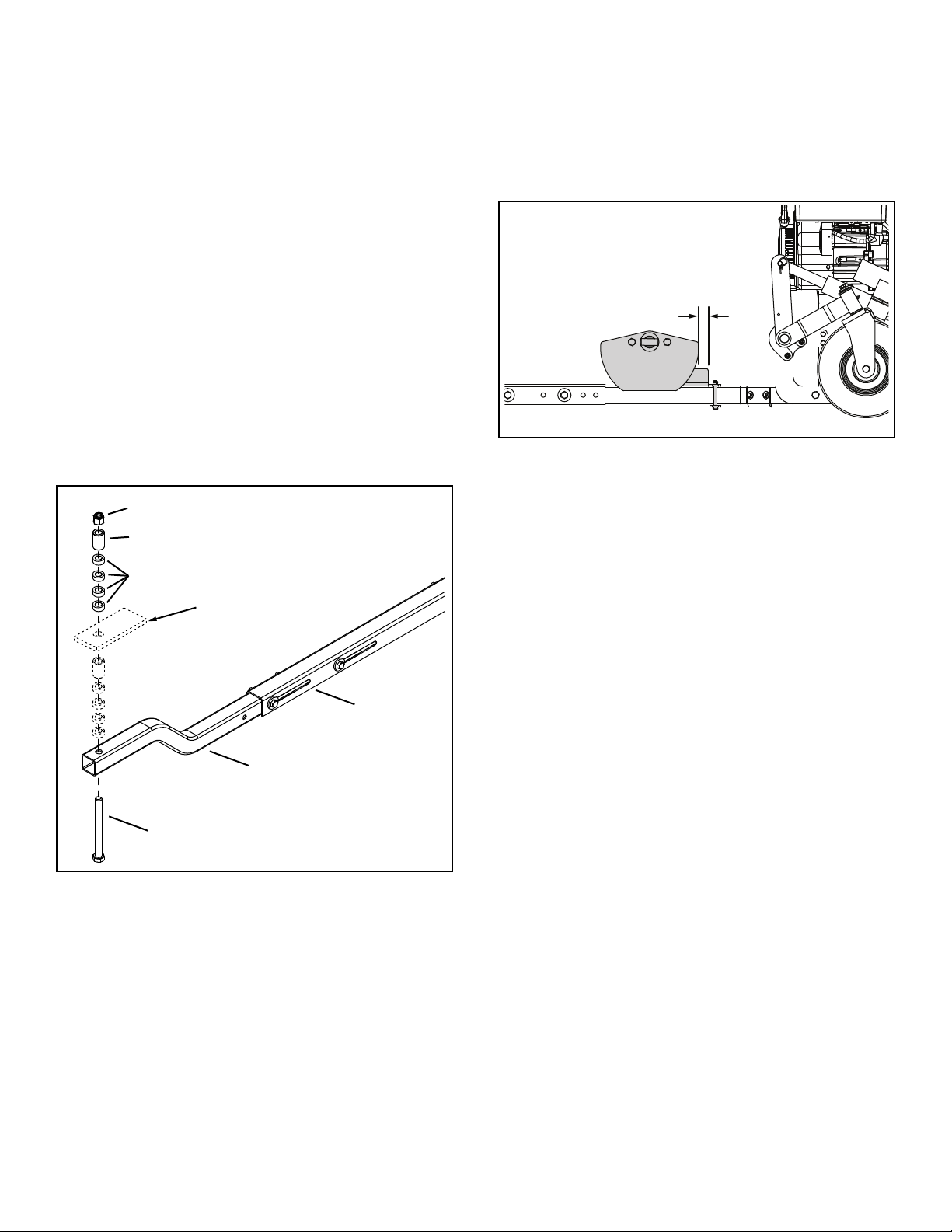
Slide the rear frame tube in or out of the push channel 42.
ATV HITCH
3/4" x 7-1/2"
HEX BOLT
3/4" NYLOCK NUT
LONG SPACER (.81" x 1.25" x 1.5")
REAR FRAME TUBE
PUSH
CHANNEL
SHORT SPACER (.75" x 1.25" x .5")
1/4"
to align it with the ATV hitch. Make sure the minimum
3"-4" clearance between the ATV and the snow thrower
is maintained.
If the rear frame tube does not slide in or out enough 43.
to align with the ATV hitch, move the bolts that fasten
the rear frame tube to the push channel to a different
set of holes. (Refer to gure 15). If alignment is still not
possible, move the bolts that fasten the push channel
to the mounting tubes to a different set of holes. (Refer
to gure 14).
Attach the rear frame tube to the ATV hitch using a 3/4" 44.
x 7-1/2" hex bolt, four (4) short spacers, a long spacer
and a 3/4" nylock nut. Place spacers above or below
the hitch as needed to maintain at least 1" clearance
with the bottom of the ATV and adequate clearance
with the ground. Tighten.
NOTE: Replace the bent rear frame tube with the straight
rear frame tube if the bent rear frame tube does not provide
adequate ground clearance and there is extra clearance
with the bottom of the ATV.
Tighten45. the nuts and bolts that fasten the push channel
to the mounting tubes, and the rear frame tube. Refer
to gures 14 and 15. Make sure the mounting tubes
stay centered with the ATV while tightening.
Slide the guide bracket along the mounting tubes until 46.
the front edge is a 1/4" in front of the front edge of the
stabilizer brackets as shown in gure 29. Tighten.
FIGURE 29
Use a grease gun to apply general purpose grease 47.
to the grease ttings in the wheel hubs and wheel
spindles. Apply until grease is forced out the ends of
the hubs and spindles.
Connect the wiring from the tethered safety switch to 48.
the bullet connector on the wire harness for the switch
on the control box.
Reconnect the actuator to the handle bar switch that 49.
was unplugged in step 11 on page 6.
CHECKLIST
Before you operate your snow thrower, please review
the following checklist to help ensure that you will
obtain the best performance from your snow thrower.
All assembly instructions have been completed with all 1.
bolts and nuts properly tightened.
Check the discharge chute for proper rotation.2.
Check operation of tilt control for upper chute.3.
FIGURE 28
Verify that the wiring is correct for the actuator and that 4.
the actuator will raise and lower the snow thrower.
Check skid shoe adjustment. (Refer to the Service and 5.
Adjustments section.
Check that the tethered safety switch will shut off the 6.
engine.
Check that the wheel hubs and wheel spindles are full 7.
of grease.
12
Page 13

OPERATION
CRANK
ROD
ON/OFF
SWITCH
HANDLE BAR
SWITCH
TETHERED SAFETY
SWITCH
CHUTE TILT
HANDLE
CLUTCH
LEVER
UPPER CHUTE
LOWER CHUTE
SPIRAL AUGERS
R.H. & L.H.
SKID SHOE
SCRAPER PLATE
KNOW YOUR SNOW THROWER
Read this owner's manual and safety rules before operating your snow thrower.
Compare the illustration below with your snow thrower to familiarize yourself with the various controls and their locations.
CHUTE TILT HANDLE — Pivots the Upper Chute up or
down to control the angle and distance of discharge.
CRANK ROD — Rotates the Lower and Upper Chutes to
control the direction of discharge.
UPPER AND LOWER DISCHARGE CHUTE — Controls
direction and height of snow discharge.
SCRAPER PLATE — Replaceable plate that absorbs
wear and impact from contact with ground.
SKID SHOE — Controls amount of clearance between the
scraper plate and the ground.
HOW TO USE YOUR SNOW THROWER
BEFORE STARTING
Use the end of assembly checklist to verify that all •
instructions have been properly completed.
Make sure the skid shoes are adjusted to maintain •
adequate ground clearance between the snow thrower
and the type of surface to be cleared. (Refer to the
Service and Adjustments section.)
Make sure the ATV engine has the correct oil for winter •
operation. Refer to ATV owner's manual.
CAUTION: Never direct discharge
towards bystanders or windows. Do not
allow anyone in front of unit.
SPIRAL AUGER, R.H. & L.H. — Feeds snow to the
impeller fan at the center of the housing.
ON/OFF SWITCH — Allows snow thrower engine to be
turned off when sitting on ATV.
HANDLE BAR SWITCH — Raises and lowers the snow
thrower.
TETHERED SAFETY SWITCH — Turns snow thrower off
when pulled out.
CLUTCH LEVER — Engages and disengages the spiral
augers.
HOW TO START YOUR SNOW THROWER
Set clutch lever to "DISENGAGED"•
Attach the pull out plug to the tethered safety switch. The •
snow thrower will not run if the plug is not attached.
Set on/off switch on control mount to "ON"•
Follow instructions in your Engine Operator's Manual •
to start the snow thrower engine, then continue below.
Board your ATV and move clutch lever on control •
mount to "ENGAGED" position
HOW TO STOP YOUR SNOW THROWER
Set clutch lever on control mount to "DISENGAGED"•
Set on/off switch on control mount to "OFF"•
Follow instructions in your Engine Operator's Manual •
to nish Stop Engine procedures.
13
Page 14

CONTROLLING SNOW DISCHARGE
To control the direction snow is thrown, the discharge •
chute has 180 degrees of rotation. Turn the crank rod
clockwise to rotate the chute to the right. Turn the crank
rod counterclockwise to rotate the chute to the left.
To control the distance snow is thrown, the upper •
section of the discharge chute pivots up and down.
Push forward on the chute tilt handle to pivot the chute
down, decreasing the distance snow is thrown. Pull
back on the handle to pivot the chute up, increasing
the distance snow is thrown.
RAISING AND LOWERING
To raise, use the handle bar switch to shorten the •
actuator.
To lower, use the handle bar switch to lengthen the •
actuator.
REMOVING SNOW
Snow removal conditions vary greatly from light uffy
snowfall to wet heavy snow. Operating instructions must
be exible to t the conditions encountered. The operator
must adapt the ATV and snow thrower to depth of snow,
wind direction, temperature and surface conditions.
Before beginning operation, thoroughly inspect the •
area of operation and remove all door mats, sleds,
boards, wires and other foreign objects.
CAUTION: Never operate the ATV snow
thrower without attaching the clip of the
tethered safety switch to your clothing.
A riderless ATV with a running snow
thrower could cause serious injury to a
fallen operator or to others.
It is advisable to operate the ATV at a slow ground •
speed for safe and efcient snow removal.
In deep, drifted or banked snow it will be necessary to •
use slow ground speed. Drive forward into the snow
and allow the spiral auger to clear the snow. Repeat
this method until a path is cleared. On the second
pass, overlap the rst enough to allow the snow
thrower to handle the snow without repeated stopping
and starting of forward motion.
In extremely deep snow, raise the snow thrower from •
the ground to remove the top layer and drive forward
only until the ATVs front tires reach the uncleared
bottom layer of snow. Depress the ATV's clutch-brake
pedal and allow the spiral auger to clear the snow.
Reverse the ATV and lower the snow thrower to the
ground. Drive the ATV forward until the snow again
becomes too deep. Repeating this process into and
out of drifts will eventually clear even the deepest of
snow piles.
If the snow thrower becomes clogged with snow or •
jammed with a foreign object, disengage the snow
thrower immediately and shut off the ATV and snow
thrower engines. Set the parking break on the ATV and
unclog the snow thrower with a wooden stick before
resuming operation.
DANGER: Shut off engine and disengage
snow thrower before unclogging discharge
chute. Unclog using a wooden stick, not
your hands.
OPERATING TIPS
Discharge snow down wind whenever possible.•
To help prevent snow from sticking to the snow thrower, •
allow the snow thrower to reach outdoor temperature
before using it. A light coat of wax may also be applied
to the inside surface of the snow thrower housing and
discharge chute.
Use tire chains to improve traction if recommended by •
your ATV owners manual.
Before the rst snowfall, remove all stones, sticks and •
other objects which could become hidden by the snow.
Permanent obstacles should be marked for visibility.
Overlap each pass slightly to assure complete snow •
removal.
14
Page 15

MAINTENANCE
CUSTOMER RESPONSIBILITIES
Read and follow the maintenance schedule and the maintenance procedures listed in this section.•
MAINTENANCE SCHEDULE
Fill in dates as you
complete regular service.
Check for loose fasteners X
Check scraper and shoes for wear X X
Cleaning X
Lubrication Section X
Check engine oil level X
Maintain engine per instructions below and in engine manual.
Before each use
Every season
After each use
Before storage
Service Dates
LUBRICATION
Oil all pivot points on the snow thrower.•
Oil pivot points of two idler arms on the clutch/idler •
assembly.
Apply penetrating oil to the control cables of the •
discharge chute.
Fill grease zerks on front wheels and spindles with •
grease.
SERVICE AND ADJUSTMENTS
CAUTION: Before servicing or adjusting
the snow thrower, shut off snow thrower and
ATV engines, remove the spark plug wire(s),
set the parking brake and remove the key
from the ignition.
SPIRAL AUGERS
The spiral augers are secured to the auger shaft with •
two shear bolts and nylock nuts. If you hit a foreign
object or if ice jams the augers, the snow thrower is
designed so that the bolts will shear.
If the augers will not turn, check to see if the shear •
bolts have sheared. See gure 30. Two replacement
shear bolts and nylock nuts have been provided with
the snow thrower. For future use order part number
710-0890A shear bolt and number 47810 nylock nut.
CHECK SCRAPER AND SHOES FOR WEAR
The scraper plate and skid shoes on the bottom of the •
snow thrower are subject to wear. To prevent damage
to the spiral auger housing, replace plate and shoes
before wear is excessive.
ENGINE MAINTENANCE
Check oil level before each use. Maintain engine oil as •
instructed in the separate engine manual.
Perform spark plug or other maintenance as instructed •
in the separate engine manual.
SKID SHOE ADJUSTMENT
The skid shoes are mounted on each side of the spiral •
auger housing. They regulate the distance the scraper
plate is raised above the plowing surface. When
removing snow from a gravel driveway or and uneven
surface, it is advisable to keep the scraper plate as
high above the surface as possible to prevent possible
damage to the spiral auger. On blacktop or concrete
surface, keep the scraper plate as close to the surface
as possible.
Raise snow thrower off the ground and place a block •
under each end of the scraper plate. Loosen the six hex
nuts securing the skid shoes to the housing. Adjust the
skid shoes up or down and retighten the nuts securely.
Adjust both skid shoes to the same height to keep the
housing and the scraper plate level. See gure 31.
SHEAR BOLT AND
NYLOCK NUT
FIGURE 30 FIGURE 31
15
Page 16

REMOVING THE BELT (Figures 32-35)
SKID PLATE
PULLEY COVER
DRIVE COVER
BRAKE ASSEMBLY
Remove the key and disconnect the spark plug wire •
from the snow thrower.
Remove the engine pulley cover, the drive cover and •
the skid plate from the snow thrower.
Disengage the snow thrower clutch.•
Remove the belt from the top pulley.•
Engage the clutch.•
Remove the belt from the bottom pulley.•
Disengage the clutch.•
Lift up on the brake assembly and slip the belt between •
the brake assembly and bottom pulley to remove the
belt from the snow thrower.
INSTALLING THE BELT
Lift up on the brake assembly and slip the belt between •
the bottom pulley and the brake assembly.
Engage the clutch.•
Install the belt around the bottom pulley.•
Disengage the clutch.•
Install the belt around the top pulley. •
Make sure the belt runs inside all of the belt keepers.•
Replace the covers.•
Replace the key and reconnect the spark plug wire.•
FIGURE 33
FIGURE 34
FIGURE 32
FIGURE 35
16
Page 17

STORAGE
STORAGE RECOMMENDATIONS
Clean the snow thrower thoroughly. Wash off any salt •
deposit which may have dried on the thrower and
housing.
Any bare metal that has become exposed should be •
painted or coated with a light oil to prevent rust.
Lubricate all pivot and wear areas.•
Store in a dry area protected from weather.•
REMOVAL INSTRUCTIONS
Lower the snow thrower to the ground.•
Unplug the actuator.•
Unplug the tethered safety switch from the wire harness •
of the control box switch.
Remove the clevis pins from the strut mount assemblies •
attached to the bottom of the ATV's front A arms and
remove the stabilizer assembly from the ATV. (Refer to
gure 9 on page 7.)
Remove the 3/4" x 7-1/2" hex bolt from the rear hitch of •
the ATV to complete removal of the snow thrower.
PARTS TO REMOVE AT END OF SEASON
Remove the A-arm brackets from the suspension •
of the ATV, especially before using your ATV for offroading, trail riding or other activities hard on the
suspension. See the owners manual of your ATV for
more information.
TROUBLESHOOTING
PROBLEM CAUSE CORRECTION
Spiral augers don't turn 1. Drive belt too loose 1. Increase tension on drive belt
2. Drive belt broken 2. Replace drive belt
3. Shear bolts are sheared. 3. Replace shear bolts
Clogged discharge chute 1. ATV ground speed too fast 1. Decrease ground speed
2. ATV throttle set too low 2. Increase to full throttle
3. Snow too deep 3. Raise snow thrower
4. Snow melts during contact with snow
thrower
Snow thrower stalls 1. Object jammed in spiral auger 1. Stop ATV and snow thrower engine,
2. Hard or heavy snow 2. Decrease ground speed
Front wheels slide instead of steering 1. Not enough traction at front wheels 1. Increase scraper plate clearance by
2. Snow thrower wheels do not have
enough lubrication
Snow thrower rides up over snow 1. ATV ground speed too fast 1. Decrease ground speed
2. Bottom snow is icy or hard packed 2. Lower the skid shoes so that front of
4. Allow snow thrower to cool to outdoor
temperature before using
disengage the snow thrower clutch
and clear the auger
lowering the skid shoes
2. Fill front grease zerks with grease
until a small amount comes out the
bottom
skid shoe is lower than the rear
17
Page 18

SÉCURITÉ
Tout appareil mécanique ou motorisé risque de provoquer des blessures si ce dernier n'est pas utilisé correctement ou si l'utilisateur ne
sait pas comment l'utiliser. Faites preuve de prudence à tout moment lorsque vous utilisez un appareil mécanique ou motorisé.
Lire ce manuel attentivement et bien connaître le •
fonctionnement de la soufeuse à neige avant de l'utiliser,
savoir comment l’arrêter et mettre rapidement les commandes
au point mort.
Ne jamais laisser d'enfants utiliser l'équipement.•
Ne jamais laisser d’adultes utiliser l’équipement sans avoir •
auparavant reçu une formation adéquate.
Interdire à quiconque de se trouver dans la zone de travail, •
particulièrement aux jeunes enfants et aux animaux de
compagnie.
Vérier particulièrement la zone où l’équipement sera utilisé •
an de retirer les paillassons, luges, planches, câbles et
autres objets étrangers.
Débrayer et mettre les commandes au point mort avant de •
démarrer le moteur.
Ne pas utiliser cet équipement sans porter des vêtements •
adéquats correspondants à la température extérieure.
Porter des chaussures qui protègent les pieds et améliorent la •
prise sur les surfaces glissantes.
Vérier le niveau de carburant avant de démarrer le moteur. Ne •
pas dévisser le bouchon du réservoir de carburant ni remplir le
réservoir pendant que le moteur fonctionne ou s’il est encore
chaud. Ne pas remplir le réservoir à l'intérieur d'un bâtiment
car l'essence est un carburant extrêmement inammable.
Ne jamais utiliser le VTT et sa soufeuse à neige sans xer •
auparavant la pince du bouton de sécurité en laisse à votre
vêtement. Un VTT sans conducteur avec une soufeuse à
neige en train de fonctionner risque de gravement blesser
tout utilisateur tombé à terre ou toute personne à proximité.
S’assurer que la hauteur de la soufeuse à neige est réglée
pour déblayer le type de surface sur laquelle elle sera
utilisée.
Ne jamais effectuer de réglage pendant que le moteur est en •
train de fonctionner.
Toujours porter des lunettes de protection ou une protection •
oculaire avant d’utiliser, de régler ou de réparer la soufeuse
à neige.
Ne pas placer les mains ni les pieds à proximité des pièces en •
mouvement. Toujours s'éloigner de l'ouverture d’éjection.
Faire preuve d’extrêmes précautions en travaillant sur des •
surfaces en gravier ou en les traversant.
Ne pas transporter de passager.•
Après avoir heurté un corps étranger, arrêter la soufeuse •
et le VTT, engager le frein sur le VTT, retirer le câble de la
bougie sur la soufeuse, et inspecter ensuite rigoureusement
la soufeuse an de s’assurer qu’elle n’est pas endommagée.
Réparer tout dégât avant de redémarrer et d'utiliser la
soufeuse à neige.
Si la soufeuse à neige commence à vibrer anormalement, •
arrêter immédiatement et rechercher la cause du problème.
Les vibrations sont généralement un avertissement préliminaire
avant l’apparition de problèmes. Arrêter le moteur de la
soufeuse et retirer le câble de la bougie à chaque fois que
l'on quitte la position de fonctionnement, avant de déboucher
la soufeuse ou de faire un réglage ou une inspection.
Prendre toutes les précautions possibles avant de laisser •
l'unité sans surveillance. Débrayer le levier d'embrayage,
abaisser la soufeuse à neige, engager le frein à main, arrêter
les moteurs de la soufeuse et du VTT et retirer les clés de
contact.
Avant de nettoyer, réparer ou inspecter la soufeuse, •
s’assurer que toutes les pièces en mouvement sont à l’arrêt.
Déconnecter le câble de la bougie et l’éloigner de cette
dernière an d’éviter tout démarrage accidentel.
Ne pas faire fonctionner le moteur de la soufeuse à neige •
à l’intérieur d’un bâtiment sauf pour l’y ranger et l’en sortir.
Ouvrir les portes vers l’extérieur. Les gaz d’échappement sont
dangereux.
Ne pas dégager la neige sur des pentes abruptes. Faire •
preuve d'une extrême prudence en changeant de direction
sur une pente. Ne pas tenter de déneiger de fortes pentes. Se
reporter au guide des pentes en page 35 de ce manuel.
Ne jamais utiliser la soufeuse à neige sans ses protections, •
plaques ou dispositifs de sécurité en place.
Ne jamais utiliser la soufeuse à neige à proximité de vitres, •
d’automobiles, de fenêtres, de dénivellation importante,
etc., sans avoir correctement réglé l’angle d’éjection de la
soufeuse.
Ne jamais orienter le conduit d'éjection vers des personnes •
alentours et ne jamais laisser quiconque se tenir devant la
soufeuse.
Ne jamais utiliser la soufeuse dans de la neige à grande •
vitesse.
Ne pas retirer la neige à trop grande vitesse pour ne pas •
risquer une surcharge de la machine.
Ne jamais utiliser la machine à de grandes vitesses sur des •
surfaces glissantes. Être extrêmement prudent et regarder
derrière soi lors d'une marche arrière.
Prendre garde à la circulation routière et demeurer vigilant •
lors d’un croisement ou à proximité d’une route.
Couper le moteur de la soufeuse an de pouvoir la transporter •
ou lorsqu'elle n'est pas utilisée.
Se référer au manuel du VTT avant d'utiliser d'autres •
équipements ou accessoires
Ne jamais utiliser la soufeuse à neige sans une bonne •
visibilité ou un bon éclairage.
18
Page 19

CONTENU DU CARTON
1
2
5
4
6
7
10
11
15
23
30
24
9
12
25
29
26
17
18
20
22
16
19
21
28
27
3
8
13
14
RÉF. QTÉ DESCRIPTION
1 1 Carter de la soufeuse
2 2 Fixation d'ancrage du carter
3 1 Bouton du guidon
4 2 Support stabilisateur
5 1 Actionneur
6 1 Jambe de force extérieure
7 1 Jambe de force intérieure
8 1 Support de guidage
9 1 Étrier de support
10 2 Bague
11 2 Barre de montage
12 1 Montage des roues
13 1 Plaque de guidage
14 1 Bague d'espacement de 3 po.
15 1 Barre de poussée
19
RÉF. QTÉ DESCRIPTION
16 4 Support de xation de 6-5/8 po.
17 2 Support de jambe de force de 6-5/8 po.
18 2 Support de jambe de force de 6-58 po.
19 2 Support de xation de 5-1/2 po.
20 2 Support de jambe de force de 5-1/2 po.
21 2 Support de xation de 4 po.
22 2 Support de jambe de force de 4 po.
23 1 Tube de cadre arrière (courbé)
24 1 Tube de cadre arrière (droit)
25 1 Commandes
26 2 Support de xation Polaris
27 1 Support de jambe de force de Polaris (G)
28 1 Support de jambe de force de Polaris (D)
29 1 Faisceau de câblage
30 1 Goulotte d'éjection
Page 20

SACS DE QUINCAILLERIE
ILLUSTRATION DES PIÈCES
NON À L’ÉCHELLE
1 2
3
5
6
7
24
25
13
17
18
12
20
19
4
21
22 23
14
15
16
11
29
28
31
8
9
10
26
27
30
32
20
Page 21

REF QTY DESCRIPTION
OFF
LO
HI
PETITS ÉCROUS À
FREIN ÉLASTIQUE
PETITES VIS
LONGUES
BRIDE
PLATE
SUPPORTS
DE GUIDON
PETITS ÉCROUS À
COLLERETTE
SUPPORT DE
L'INTERRUPTEUR
OFF
LO
HI
PETITE VIS
COURTE
PETIT ÉCROU À
FREIN ÉLASTIQUE
1 3 Axe à épaulement de 1/2 x 3 po.
2 1 Axe à épaulement de 1/2 x 2 po.
3 4 Boulon hexagonal de 5/16-18 x 1 po.
4 4 Boulon hexagonal de 1/2-13 x 3-1/2 po.
5 25 Rondelle de 1/2 x 1-1/2 po.
6 2 Boulon hexagonal de 5/16-18 x 3 po.
7 4 Boulon hexagonal de 3/8-16 x 2 po.
8 4 Goupille fendue
9 2 Rondelle frein de 1 x 0,32 po.
10 10 Rondelle de 5/16 po.
11 10 Boulon hexagonal de 1/2-13 x 2-1/4 po.
12 1 Boulon hexagonal de 1/2-13 x 1-1/2 po.
13 6 Boulon hexagonal à embase de 1/4-20 x 1 po.
14 6 Écrou à collerette de 1/4-20
15 18 Écrou à frein élastique de 5/16-18
16 4 Écrou à frein élastique de 3/8-16
ASSEMBLAGE
REF QTY DESCRIPTION
17 19 Écrou à frein élastique de 1/2-13
18 2 Écrou de blocage de 1/2-13
19 2 Boulon de carrosserie de 5/16-18 x 1-3/4 po.
20 2 Boulon de carrosserie de 5/16-18 x 1 po.
21 2 Boulon de carrosserie de 5/16-18 x 1-1/4 po.
22 2 Boulon hexagonal de 5/16-18 x 1-1/2 po.
23 2 Boulon hexagonal de 5/16-18 x 1-3/4 po.
24 2 Bague d'espacement de 0,5 x 1 x 0,59 po.
25 1 Bague d'espacement de 0,81 x 1,25 x 1,5 po.
26 1 Écrou à frein élastique de 3/4-10
27 4 Bague d'espacement de 0,75 x 1,25 x 0,5 po.
28 1 Boulon hexagonal de 3/4-10 x 7-1/2 po.
29 2 Boulon hexagonal de 1/2-13 x 4-1/2 po.
30 3 Gâche de la goulotte d'éjection
31 8 Attache en nylon
32 2 Boulons de Cisaillement
OUTILS NÉCESSAIRES
Clé de 5/16 po. (1)
Clé de 3/8 po. (1)
Clé de 7/16 po. (1)
Clé de 1/2 po (2)
Clé de 9/16 po (2)
Clé de 3/4 po (2)
Clé de 1-1/6 po. (1) ou clé réglable
Clé de 1-1/8 po. (1) ou clé réglable
Tournevis cruciforme Phillips (1)
Ciseaux ou couteau (1)
Pistolet graisseur avec graisse tout usage (1)
Clé hexagonale Allen de 3/16 po (1)
Bloc en béton de 15 po. (38 cm) (1)
FAISCEAU DE CÂBLAGE
Monter deux (2) supports de guidon et une (1) bride plate de 1.
guidon sur les poignées du guidon à l'aide de deux (2) petites
vis longues et de deux (2) petits écrous à frein élastique. Ne
pas serrer pour l’instant.
Monter le support de l'interrupteur sur l'interrupteur de guidon 2.
à l'aide de deux (2) petits écrous à collerette. Serrer.
ILLUSTRATION 2
Monter le support de l'interrupteur sur la bride plate à l'aide 3.
d'une (1) petite vis courte et d'un (1) petit écrou à frein
élastique. Voir l’illustration 3. Ne pas serrer pour l’instant.
Faire pivoter l'interrupteur jusqu'à ce qu'il soit à l'angle 4.
approprié, puis serrer les vis et les écrous assemblés aux
étapes 1 et 3.
ILLUSTRATION 1
ILLUSTRATION 3
21
Page 22

Fixer la boîte-relais en sécurité près de la batterie du VTT ou 5.
BATTERIE
+
BORNE
POSITIVE
NOIR
ROUGE
FUSIBLE
BUTON DU
GUIDON
CONDUCTEURS
BOÎTE-RELAIS
L'ACTIONNEUR
3 FILS
CONDUCTEURS
2x4
AWD
PRÉMONTÉS
VIS
PRÉMONTÉS
ÉCROUS
à un autre endroit sécuritaire sur le VTT.
Passer les 3 ls conducteurs de la boîte-relais à travers le 6.
châssis du véhicule sur le même côté que l'interrupteur sur
la poignée. Éviter de faire passer les ls près de pièces en
mouvement, des pièces chaudes et des points de pincement.
Utiliser 1 ou 2 attaches en plastique pour maintenir les ls
en place.
Connecter les trois ls conducteurs de l'interrupteur aux trois 7.
ls conducteurs de la boîte-relais, en faisant correspondre
entre eux les ls rouges, verts et noirs. Voir l’illustration 4.
Passer les deux ls conducteurs de la boîte-relais à travers 8.
le châssis du véhicule. Éviter de faire passer les ls près
de pièces en mouvement, qui chauffent ou d'endroits qui
coincent. Utiliser 1 ou 2 attaches pour maintenir les ls en
place.
Brancher le connecteur de la boîte-relais dans le connecteur 9.
de l'actionneur.
Raccorder le l rouge du fusible à la borne positive de la 10.
batterie du VTT. Raccorder le l négatif (l noir) à la borne
négative sur la batterie.
Utiliser l’interrupteur du guidon an d'allonger complètement 11.
l’actionneur puis débranchez l’actionneur.
Fixer le bouton de sécurité en laisse au guidon en utilisant les 12.
quatre (4) vis et écrous prémontés. Se référer à l’illustration
5.
Faire passer le câblage à travers le VTT et le faire ressortir 13.
à l’avant. Éviter de faire passer le l à proximité des pièces
en mouvement, des pièces chaudes ou des points de
pincement. Il est possible d'utiliser des attaches en nylon
an de maintenir le l en place.
ILLUSTRATION 5
ILLUSTRATION 4
22
Page 23

4 po.
Polaris
5-1/2 po.
6-5/8 po.
6-5/8 po.
Bombardier
Outlander
5/16 po. x
1-1/2" po.
1/2 po. x
2-1/4 po.
3/8 po. x 2 po.
3/8 po. x 2 po.
3/8 po. x 2 po.
3/8 po. x 2 po.
bras inférieurs
A du VTT
ASSEMBLAGE DE LA SOUFFLEUSE
BOULONS
HEXAGONAUX
DE 1/2 PO.
X 4-1/2 PO.
SUPPORTS
STABILISATEURS
ÉCROUS À FREIN
ÉLASTIQUE DE 1/2 PO.
LONGUES BAGUES
D’ESPACEMENT DE 3 PO.
JAMBE DE FORCE EXTÉRIEURE
BAGUE
BAGUE
JAMBE DE
FORCE INTÉRIEURE
AXES À ÉPAULEMENT
DE 1/2 PO. X 3 PO.
AXES À ÉPAULEMENT
DE 1/2 PO. X 3 PO.
GOUPILLE
FENDUE
GOUPILLE FENDUE
Enlever tout dispositif de protection du joint homocinétique de 1.
l'avant des bras inférieurs A du VTT. Sélectionner le support
de jambe de force indiqué à l’illustration 6 et correspondant
à la marque du VTT. Si le VTT n'est pas mentionné à
l’illustration 6, commencer avec le montage de jambe de
force de 5-1/2 po. Si les montages de supports de jambe de
force de 4 po., 5-1/2 po. ou de 6-5/8 po. sont utilisés, xer en
mettant le support de jambe de force bras A et les boulons à
l'extérieur du bras A. Ne pas serrer pour l’instant.
Glisser une bague sur l’extrémité de la jambe de force 3.
extérieure.
Glisser la jambe de force extérieure à travers les supports 4.
qui ont été installés lors de l’étape 2.
Glisser une seconde bague sur l’extrémité de la jambe de 5.
force extérieure.
Appliquer une ne couche d'huile sur la jambe de force 6.
intérieure puis l’insérer dans la jambe de force extérieure.
Serrer les boulons qui ont été installés lors de l’étape 2.7.
ILLUSTRATION 8
Assembler les supports stabilisateurs en utilisant deux (2) 2.
boulons hexagonaux de 1/2 po. x 4-1/2 po., deux (2) longues
bagues d’espacement de 3 po. et deux (2) écrous à frein
élastique de 1/2 po. comme indiqué sur l’illustration 7. Ne
pas serrer pour l’instant.
Fixer les extrémités des jambes de force extérieure et 8.
intérieure aux supports des jambes de force qui ont été
ILLUSTRATION 6
installés sur les bras A du VTT. Utiliser deux (2) axes à
épaulement de 1/2 po. x 3 po. et deux (2) goupilles fendues.
Serrer les boulons et les écrous qui ont été installés lors de 9.
l’étape 1 et retiennent les supports des jambes de force aux
bras A.
Centrer les supports stabilisateurs sous le VTT. Glissez les 10.
bagues vers le haut an de les placer contre les supports
stabilisateurs et serrer les vis sans tête dans les bagues. Les
supports stabilisateurs doivent pouvoir tourner librement
après avoir serré les bagues.
REMARQUE: Pour des raisons de clarté, le VTT n'est pas indiqué
pas sur le dessin ci-dessous.
ILLUSTRATION 9
ILLUSTRATION 7
23
Page 24

Placer le bloc de béton de 15 po. (38 cm) sous la soufeuse 11.
RONDELLE DE
1/2 X 1-1/2 PO.
ÉCROU À FREIN
ÉLASTIQUE
ANGLE EN
ARRIÈRE
BOULON HEXAGONAL
DE 1/2-13 X 2-1/4 PO.
FIXATION
D'ANCRAGE
DU CARTER
BARRE DE
MONTAGE
ÉCROU À FREIN
ÉLASTIQUE DE
1/2 PO.
RONDELLE DE 1/2 PO.
BARRE DE
POUSSÉE
BOULON
HEXAGONAL
DE 1/2-13
X 3-1/2 PO.
ÉCROUS DE BLOCAGE
DE 1/2 PO.
RONDELLE DE 1/2
ÉCROU À FREIN
ÉLASTIQUE DE 1/2 PO.
BOULON HEXAGONAL
DE 1/2-13 X 2-1/4 PO.
à neige, sous le moteur. Se référer à l’illustration 10.
Fixer les trous avant des xations d'ancrage du carter aux 13.
boulons soudés sur le carter à l'aide de deux (2) écrous de
blocage de 1/2 po. Ne pas serrer pour l’instant.
ILLUSTRATION 12
Verrouiller les barres de montage aux brides plates latérales 14.
de support à l'aide de deux (2) boulons hexagonaux de 1/2
x 2-1/2 po., quatre (4) rondelles de 1/2 po. (une sur chaque
ILLUSTRATION 10
côté) et deux (2) écrous à frein élastique de 1/2 po. Ne pas
serrer pour l’instant.
Mettre une xation d'ancrage du carter à l'extérieur de chaque 12.
barre de montage à l'aide de quatre (4) boulons hexagonaux
de 1/2 x 2-1/4 po., de huit (8) rondelles de 1/2 po. (une sur
chaque côté) et quatre (4) écrous à frein élastique de 1/2 po.
Ne pas serrer pour l’instant.
ILLUSTRATION 13
Placer la barre de poussée au dessus des extrémités 15.
des barres de montage. Aligner les trous comme l'indique
l’illustration ci-dessous et verrouiller la barre de poussée à
l'aide de deux (2) boulons hexagonaux de 1/2 x 3-1/2 po.,
quatre (4) rondelles de 1/2 po. (une sur chaque côté) et
quatre (2) écrous à frein élastique de 1/2 po. Ne pas serrer
pour l’instant.
ILLUSTRATION 11
ILLUSTRATION 14
24
Page 25

Fixer le tube du cadre arrière (courbé) à la barre de poussée 16.
ÉCROU À
FREIN
ÉLASTIQUE
DE 1/2 PO.
RONDELLE
DE 1/2 PO.
BOULON HEXAGONAL
DE 1/2-13 X 3-1/2 PO.
TUBE DU CADRE
ARRIÈRE
ÉCROU À FREIN
ÉLASTIQUE DE 5/16 PO.
BOULON HEXAGONAL
DE 5/16-18 X 1-3/4 PO.
RONDELLE DE
5/16 PO.
RONDELLE DE
5/16 PO.
AXE À ÉPAULEMENT
DE 1/2 X 3 PO.
AXE À ÉPAULEMENT
DE 1/2 X 2 PO.
BAGUE D'ESPACEMENT
DE 0,5 X 1 X 0,59 PO.
GOUPILLE
FENDUE
BOULON HEXAGONAL
DE 5/16 X 1 PO.
BOULON HEXAGONAL
DE 1/2 X 2-1/4 PO.
RONDELLE
DE 1/2 PO.
ÉCROU À FREIN
ÉLASTIQUE DE
5/16 PO.
ÉCROU À FREIN
ÉLASTIQUE
DE 1/2 PO.
SUPPORT
D'ANCRAGE
à l'aide de deux (2) boulons hexagonaux de 1/2 x 3-1/2 po.,
quatre (4) rondelles de 1/2 po. (une sur chaque côté) et
quatre (2) écrous à frein élastique de 1/2 po. Ne pas serrer
pour l’instant.
Retirer le bloc de béton de sous le moteur et le placer sous 17.
l’extrémité du tube du cadre arrière.
Placer le montage des roues derrière la base de montage 19.
du moteur.
Fixer le bas des supports d'ancrage (partie intégrante du 20.
montage des roues) sur l'extérieur des barres de montage
en utilisant quatre (4) boulons hexagonaux de 1/2 po. x 2-1/4
po. et quatre (4) rondelles de 1/2 po. (à l'intérieur de la barre
de montage) et quatre (4) écrous à frein élastique de 1/2 po.
Ne pas serrer pour l’instant.
Fixer le dessus des supports d'ancrage à la base de montage 21.
du moteur en utilisant quatre (4) boulons hexagonaux de
5/16 po. x 1 po. et quatre (4) écrous à frein élastique de 5/16
po. Ne pas serrer pour l’instant
Serrer tous les écrous et tous les boulons qui ont été 22.
installés lors des étapes 12 à 14 et 18 à 21. Ne pas serrer
pour l’instant les boulons et les écrous qui ont été installés
lors des étapes 15 et 16.
REMARQUE: Pour des raisons de clarté, le montage des roues
n'est pas indiqué pas sur le dessin.
Fixer la bride plate de support aux barres de montage à 18.
l'aide de quatre (4) boulons hexagonaux de 5/16 x 1-3/4 po.,
huit (8) rondelles de 5/16 po. (l'une à l'intérieur et l'autre à
l'extérieur) et quatre (4) écrous à frein élastique de 5/16 po.
Ne pas serrer pour l’instant.
ILLUSTRATION 15
ILLUSTRATION 17
REMARQUE: Avant de passer à la prochaine étape, s’assurer
que l’actionneur est complètement sorti. Voir l’étape 11 de la
page 22 du Faisceau de câblage.
Fixer le haut de l'actionneur au montage des roues à l'aide 23.
d'un (1) axe à épaulement de 1/2 x 3 po., deux (2) bagues
d'espacement de 0,5 x 1 x 0,59 po. et d'une (1) goupille
fendue de 3/32 po.
Fixer le bas de l'actionneur au support de l'actionneur à 24.
l'aide d'un (1) axe d'épaulement de 1/2 x 2 po. et d'une (1)
goupille fendue de 3/32 po.
ILLUSTRATION 16
ILLUSTRATION 18
25
Page 26

Assembler le support de guidage et la plaque de guidage aux 25.
BOULON
HEXAGONAL
DE 5/16 X 1-1/2 PO.
ÉCROU À FREIN
ÉLASTIQUE DE 5/16 PO.
PLAQUE
DE GUIDAGE
SUPPORT
DE GUIDAGE
GRAISSE
BOULON HEXAGONAL À
EMBASE DE 1/4-20 X 1 PO.
ÉCROU À
COLLERETTE
DE 1/4-20
BOULON HEXAGONAL DE
1/2-13 X 1-1/2 PO.
RONDELLE DE 5/16 PO.,
ÉCROU À FREIN ÉLASTIQUE
DE 5/16 PO.
barres de montage en utilisant deux (2) boulons hexagonaux
de 5/16 po. x 3 po. et deux (2) écrous à frein élastique de
5/16 po. Ne pas serrer pour l’instant.
Retirer le bloc en béton du dessous du tube du cadre 26.
arrière.
Placer la goulotte d'éjection (avec l'ouvertuire vers l'avant) 28.
dans l'anneau. Fixer trois (3) gâches de la goulotte d'éjection
(le côté droit vers le haut, comme indiqué) au bas du rebord
à l'aide de six (6) boulons hexagonaux à embase de 1/4 x 1
po. et six (6) écrous de blocage à collerette de 1/4 po. Serrer
avec précaution de sorte que les écrous soient bien ajustés
sans mordre dans les gâches en plastique de la goulotte
d'éjection.
ILLUSTRATION 19
Recouvrir le haut de l'anneau entourant l'ouverture d'éjection 27.
avec une graisse tout usage.
ILLUSTRATION 21
Assembler les commandes à la base de montage du moteur 29.
à l'aide d'un (1) boulon hexagonal de 1/2 x 1-1/2 po., une
rondelle de 1/2 po. (à l'intérieur de la base de montage) et
un écrou à frein élastique de 1/2 po. Ne pas serrer pour
l’instant.
ILLUSTRATION 20
ILLUSTRATION 22
26
Page 27

BOULON DE
CARROSSERIE DE
5/16-18 X 1 PO.
RONDELLE
DE 5/16 PO.
ÉCROU À FREIN
ÉLASTIQUE DE
5/16-18
FIXER LES CÂBLES
ATTACHE EN NYLON
RONDELLES
FREINS ET DEUX
COMMANDE
D'INCLINAISON
ÉCROUS À
FREIN ÉLASTIQUE
DE 5/16 PO.
BOULONS DE
CARROSSERIE
DE 5/16 X 1-3/4 PO.
SUPPORTS STABILISATEURS
SUPPORT DE GUIDAGE
BOULONS DE CARROSSERIE
DE 5/16-18 X 1-1/4 PO.
ÉCROUS À FREIN
ÉLASTIQUE DE 5/16 PO.
Assembler les commandes au montage de la soufeuse à 30.
l'aide de deux (2) boulons de carrosserie de 5/16 x 1-1/4 po.
et de deux (2) écrous à frein élastique de 1/4 po. Ne pas
serrer pour l’instant.
Serrer les boulons qui ont été assemblés lors des étapes 29 31.
et 30.
Couper l'attache en plastique retenant ensemble les deux 32.
pièces du support de la bielle de la goulotte d'éjection.
Attacher les supports de la bielle à l'adaptateur de la goulotte 33.
d'éjection à l'aide de deux (2) boulons de carrosserie de 5/16
x 1 po., deux (2) rondelles de 5/16 po. et deux (2) écrous à
frein élastique de 5/16 po. Ne pas serrer pour l’instant.
Régler la position des supports du réglage de la goulotte 34.
d'éjection de manière à ce que la spirale ne touche pas le
bas des crans de la goulotte d'éjection
Serrer les boulons et écrous assemblés aux étapes 33. 35.
ILLUSTRATION 25
Insérer le faisceau de câblage dans le grand trou à l'avant du 38.
boîtier de commande.
Brancher les connecteurs du faisceau de câblage dans 39.
l'interrupteur.
ILLUSTRATION 23
À l'aide d'attaches en plastique, attacher fermement tous les 40.
ls et tous les câbles au montage de la poignée pour qu'ils
n'interfèrent pas avec les pièces en mouvement.
Fixer la commande d'inclinaison de la goulotte d'éjection aux 36.
commandes à l'aide de deux (2) boulons de carrosserie de
5/16 x 1-3/4 po., deux (2) rondelles freins et deux (2) écrous
à frein élastique de 5/16 po.
Utiliser une attache en nylon an de xer les câbles de 37.
commande de la goulotte d'éjection à la barre de support
comme indiqué sur l’illustration 25
REMARQUE: Ne pas xer les câbles de commande de la
goulotte d'éjection à des emplacements autres que ceux indiqués
ci-dessous.
ILLUSTRATION 26
Avancer le VTT derrière la soufeuse à neige, en veillant à 41.
ce que la barre de poussée demeure bien centrée entre les
supports stabilisateurs. S'assurer que le support de guidage
glisse entre les supports stabilisateurs comme indiqué sur
l’illustration 27. Veiller à laisser un espace minimum de 7,6 à
10 cm entre l’avant du VTT et la soufeuse à neige.
REMARQUE: Pour des raisons de clarté, le VTT n'est pas indiqué
pas sur le dessin.
ILLUSTRATION 24
ILLUSTRATION 27
27
Page 28

Glisser le tube du cadre arrière vers l'intérieur ou l’extérieur 42.
ATTELAGE DU VTT
TUBE DU CADRE ARRIÈRE
BARRE DE
POUSSÉE
ÉCROUS À FREIN ÉLASTIQUE DE 3/4 PO.
BOULON HEXAGONAL DE 3/4 PO. X 7-1/2 PO.
BAGUES D’ESPACEMENT COURTES
(.75 PO. x 1.25 PO. x .5 PO.)
LONGUE BAGUE D’ESPACEMENT
(.81 PO. x 1.25 PO. x 1.5 PO.)
6 mm
de la barre de poussée an de l’aligner avec la plaque
d’attelage du VTT. Veiller à maintenir l’espace minimum de
7,6 à 10 cm entre le VTT et la soufeuse à neige.
Si le tube du cadre arrière ne glisse pas sufsamment an de 43.
pouvoir l’aligner avec la plaque d’attelage du VTT, déplacer
les boulons qui retiennent le tube du cadre arrière à la barre
de poussée et utiliser d’autres trous (voir illustration 15). Si
l’alignement ne peut toujours pas être effectué, déplacer les
boulons qui retiennent la barre de poussée aux barres de
montage et utiliser d’autres trous (voir illustration 14).
Fixer le tube du cadre arrière à la plaque d’attelage du VTT 44.
en utilisant un (1) boulon hexagonal de 3/4 po. x 7-1/2 po.,
quatre (4) bagues d’espacement courtes, une (1) longue
bague d’espacement et un (1) écrous à frein élastique de
3/4 po. Placer les bagues d’espacement au-dessus et en-
dessous de la plaque d’attelage an de conserver un espace
de 2,5 cm sous le VTT et un dégagement sufsamment entre
le sol et le dispositif. Serrer les boulons et les écrous.
REMARQUE: Remplacer le tube courbé du cadre arrière par le
tube droit du cadre arrière si le tube courbé du cadre arrière
n’offre pas un dégagement sufsamment entre le sol et le
dispositif et s’il y a sufsamment d'espace sous le VTT.
Serrer les écrous et les boulons qui retiennent la barre 45.
de poussée aux barres de montage et le tube du cadre
arrière. Voir illustrations 14 et 15. S’assurer que les barres
de montage demeurent centrées sur le VTT lorsque les
xations sont serrées.
Glisser le support de guidage le long des barres de montage 46.
jusqu’à ce que la bord avant se trouve à 6 mm devant le
bord avant des supports stabilisateurs comme indiqué sur
l’illustration 29 puis serrer.
ILLUSTRATION 29
Utiliser un pistolet à graisse an d’appliquer une graisse tout 47.
usage sur les pièces des moyeux des roues et des axes.
Appliquer sufsamment de graisse jusqu’à ce qu’elle sorte
par les extrémités des moyeux et des axes.
Raccorder les ls du bouton de sécurité en laisse au 48.
connecteur du faisceau de câblage du bouton du boîtier de
commande.
Rebrancher l’actionneur à l’interrupteur du guidon qui avait 49.
été débranché lors de l’étape 11 de la page 22.
LISTE DE VÉRIFICATION
Avant d’utiliser la soufeuse à neige, revoir la liste de
véricationsuivanteandes’assurerquelasoufeusesera
la plus performante possible.
Toutes les instructions de montage doivent avoir été suivies 1.
et les boulons et écrous doivent être serrés correctement.
Vérier la bonne rotation de la goulotte d’éjection.2.
Vérier le fonctionnement de la commande d’inclinaison 3.
pour la goulotte d’éjection supérieure.
Vérier si le câblage de l'actionneur est correct et si ce 4.
ILLUSTRATION 28
dernier lève ou abaisse la soufeuse.
Vérier le réglage des patins. (Se référer à la section 5.
Entretien et réglage.)
S’assurer que le bouton de sécurité en laisse fonctionne 6.
correctement et permet de couper le moteur.
S’assurer que les moyeux et les axes des roues sont remplis 7.
de graisse.
28
Page 29

CRANK
ROD
ON/OFF
SWITCH
HANDLE BAR
SWITCH
TETHERED SAFETY
SWITCH
CHUTE TILT
HANDLE
CLUTCH
LEVER
UPPER CHUTE
LOWER CHUTE
SPIRAL AUGERS
R.H. & L.H.
SKID SHOE
SCRAPER PLATE
UTILISATION
BIEN CONNAÎTRE LA SOUFFLEUSE
Lirecemanueldupropriétaireetlesrèglesdesécuritéavantd’utiliserlasoufeuse.
Comparer l’illustration ci-dessous avec la soufeuse an de se familiariser avec les diverses commandes et leurs emplacements.
GOULOTTE
D’ÉJECTION
GOULOTTE
D’ÉJECTION
INFÉRIEURE
TARIÈRES GAUCHE
ET DROITE
SUPÉRIEURE
PLAQUE D’USURE
POIGNÉE D’INCLINAISON
DE LA GOULOTTE
D’ÉJECTION
BOUTON DE SÉCURITÉ
PATIN
BOUTON
ON/OFF
EN LAISSE
LEVIER
D'EMBRAYAGE
BIELLE
D’INCLINAISON DES
GOULOTTES
BOUTON DE
GUIDON
POIGNÉE D’INCLINAISON DE LA GOULOTTE D’ÉJECTION
Pivote la goulotte d’éjection vers le haut ou vers le bas pour
contrôler l’angle et la distance de l’éjection.
BIELLE D’INCLINAISON DES GOULOTTES Fait tourner les
goulottes d’éjection supérieure et inférieure an de contrôler la
direction de l’éjection.
GOULOTTE D’ÉJECTION SUPÉRIEURE ET INFÉRIEURE
Contrôle la direction et la hauteur de l’éjection de neige.
PLAQUE D’USURE Plaque remplaçable qui s’use et absorbe
les impacts à la suite du contact avec le sol.
COMMENT UTILISER LA SOUFFLEUSE
AVANT DE COMMENCER
Se reporter à la n de la liste de vérication de l'assemblage •
pour vérier si les instructions ont été correctement suivies.
S’assurer que les patins sont réglés de manière à maintenir •
un espace libre adéquat avec le sol entre la soufeuse et le
type de surface à déblayer. (Se référer à la section Entretien
et réglage).
S’assurer que l’huile de moteur du VTT est bien celle qu’on •
utilise en hiver. Se référer au manuel du propriétaire du VTT.
AVERTISSEMENT: Ne jamais diriger
l’éjection en direction de passants ou de
fenêtres. Interdire à toute personne de se
mettre devant l’unité.
29
PATIN Contrôle l’espace libre entre la plaque d’usure et le sol.
TARIÈRES GAUCHE ET DROITE Alimentent en neige le venti-
lateur de la turbine au centre du carter.
BOUTON ON/OFF (marche/arrêt) Permet d'arrêter le moteur
de la soufeuse tout en restant assis sur le VTT.
BOUTON DE GUIDON Soulève et baisse la soufeuse.
BOUTON DE SÉCURITÉ EN LAISSE Arrête la soufeuse
quand il est retiré du coupe-circuit.
LEVIER D’EMBRAYAGE Permet d’embrayer et de débrayer les
tarières en spirale.
COMMENT FAIRE DÉMARRER LA SOUFFLEUSE
COMMENT ARRÊTER LA SOUFFLEUSE
Mettre le levier d’embrayage sur le boîtier de commande en •
position de débrayage.
Fixez la che amovible sur bouton de sécurité en laisse. La •
soufeuse à neige ne fonctionnera pas si la che n'est pas
xée.
Mettre le bouton marche/arrêt en position ON (marche). •
Suivre les instructions du manuel de l'utilisateur du moteur pour •
mettre la soufeuse en marche, puis continuer comme suit.
Monter sur le VTT et mettre le levier en position •
d'embrayage.
Désengager le levier d’embrayage sur le boîtier de commande.•
Mettre le bouton marche/arrêt sur le boîtier de commande •
en position OFF (arrêt).
Suivre les instructions du manuel de l'utilisateur concernant •
le moteur pour nir la procédure d'arrêt du moteur.
Page 30

CONTRÔLER L’ÉJECTION DE LA NEIGE
Pour contrôler la direction dans laquelle la neige est projetée, •
la goulotte d’éjection de la décharge a une rotation de 180
degrés. Tourner la bielle d’inclinaison des goulottes dans le
sens des aiguilles d’une montre pour faire tourner la goulotte
vers la droite. Tourner la bielle d’inclinaison des goulottes
dans le sens contraire pour faire tourner la goulotte vers la
gauche.
Pour contrôler la distance à laquelle la neige est projetée, la •
section supérieure de la goulotte d’éjection de la décharge
pivote vers le haut et vers le bas. Pousser la poignée
d’inclinaison des goulottes an de pivoter la goulotte
d’éjection vers le bas, diminuant ainsi la distance à laquelle
la neige est projetée. Tirer la poignée pour faire pivoter la
goulotte vers le haut, augmentant ainsi la distance à laquelle
la neige est projetée.
LEVER ET BAISSER
Pour lever, utiliser le bouton du guidon pour ramener •
l’actionneur.
Pour abaisser, utiliser le bouton du guidon pour allonger •
l’actionneur.
ENLEVER LA NEIGE
Les conditions de déblayage varient beaucoup, la neige pouvant
être légère, ou lourde et mouillée. Les instructions d’utilisation
doivent être assouplies pour s’adapter aux circonstances. Le
conducteur doit adapter le VTT et la soufeuse à la profondeur
de la neige, la direction du vent, la température et les conditions
de surface.
Avant d’utiliser la soufeuse, bien inspecter la zone à •
déblayer et enlever les paillassons, les luges, les planches,
les câbles et tout autre corps étranger.
Il est conseillé de faire fonctionner le VTT à une vitesse au •
sol plus lente (première vitesse) pour enlever la neige en
toute sécurité et avec efcacité.
Quand la neige est profonde, forme des congères ou •
s’amoncelle, il peut être nécessaire d'utiliser une faible
vitesse au sol. Avancer dans la neige et laisser la tarière
déblayer la neige. Répéter cette méthode jusqu’à ce qu’un
chemin soit ouvert. Lors du second passage, chevaucher
sufsamment sur le premier pour permettre à la soufeuse
de traiter la neige en évitant de s’arrêter et de redémarrer
trop souvent.
Quand la neige est extrêmement profonde, soulever la •
soufeuse du sol pour enlever la couche supérieure et
n’avancer que jusqu’à ce que les pneus avant du VTT
atteignent la couche inférieure de la neige qui n’a pas encore
été nettoyée. Appuyer sur la pédale de frein de l’embrayage
du VTT et laisser la tarière déblayer la neige. Reculer le
VTT et abaisser la soufeuse au sol. Faire avancer le VTT
jusqu’à ce que la neige devienne à nouveau trop profonde.
En répétant ce processus d’aller et venue, même les amas
de neige les plus profonds niront par être déblayés.
Si la soufeuse à neige s’avère bouchée avec de la neige ou •
si un objet se loge à l’intérieur et bloque le fonctionnement
de la soufeuse, débrayer immédiatement la soufeuse et
couper le moteur du VTT ainsi que celui de la soufeuse.
Mettre le frein à main du VTT et retirer la neige qui bouche
la soufeuse en utilisant un bâton avant de remettre la
soufeuse en marche.
DANGER: Éteindre le moteur et débrayer la
soufeuse avant de déboucher la goulotte
d’éjection de la décharge. Déboucher avec un
bout de bois, jamais avec les mains.
ATTENTION: Ne jamais utiliser le VTT et sa
soufeuse à neige sans xer auparavant la
pince du bouton de sécurité en laisse à votre
vêtement. Un VTT sans conducteur avec une
soufeuse à neige en train de fonctionner
risque de gravement blesser tout utilisateur
tombé à terre ou toute personne à proximité.
CONSEILS PRATIQUES D’UTILISATION
Éjecter la neige dans le sens du vent, si possible.•
Attendre que la soufeuse soit à la température extérieure •
avant de s’en servir, de manière à éviter que la neige colle à
la soufeuse. Une légère couche de cire peut également être
appliqué à l’intérieur de la surface du carter de la soufeuse
et de la goulotte d’éjection de la décharge.
Mettre des chaînes antidérapantes pour améliorer la traction •
si le manuel du propriétaire du VTT le recommande.
Avant la première chute de neige, enlever toutes les pierres, •
les bouts de bois et les autres objets que la neige pourrait
cacher. Les obstacles permanents devraient être marqués
pour assurer leur visibilité.
Chevaucher légèrement sur le passage précédent pour •
enlever complètement la neige.
30
Page 31

ENTRETIEN
RESPONSABILITÉS DE L'UTILISATEUR
Lire et suivre le planning et les procédures d’entretien énumérées dans cette section•
PLANNING D’ENTRETIEN
Remplir les cases suivantes en indiquant la date à fois que
vous procédez à l'entretien
Avant chaque utilisation
Vérier si tout est bien attaché X
Vérier l’usure de la plaque et des patins X X
Nettoyage X
Section lubrication X
Chaque saison
Après chaque utilisation
Avant rangement
Dates des opérations d'entretien
LUBRIFICATION
Huiler tous les points de pivot sur la soufeuse.•
Huiler tous les points de pivot sur les deux bras de renvoi de •
l’ensemble embrayage et galet tendeur.
Mettre de l’huile pénétrante sur les câbles de commande de •
la goulotte d’éjection de la décharge.
Remplir de graisse les embouts de graissage sur les roues •
avant.
ENTRETIEN ET RÉGLAGES
AVERTISSEMENT: Avant de procéder à l'entretien
ou au réglage de la soufeuse, arrêter le moteur,
enlever le ou les ls de bougies d’allumage, serrer le
frein à main et retirer la clé de contact du tracteur.
TARIÈRES
Les tarières sont xées fermement à l’arbre de tarière à •
l’aide de deux boulons de cisaillement et d'écrous à frein
élastique. La soufeuse est conçue de manière à ce que les
boulons se cassent si la soufeuse touche un corps étranger
ou si de la glace coince les tarières.
Si les tarières ne tournent pas, vérier si les boulons de •
cisaillement se sont cassés. Voir l’illustration 30. Deux
boulons de cisaillement et deux écrous à frein élastique sont
fournis avec la soufeuse. En prévision, commander les
pièces no. 710-0890A pour les boulons de cisaillement et
les pièces no. 47810 pour les écrous à frein élastique.
VÉRIFIER L’USURE DE LA PLAQUE ET DES PATINS
La plaque d’usure et les patins au bas de la soufeuse •
peuvent s’user. Pour éviter d’endommager le carter de la
tarière, remplacer la plaque d’usure et les patins avant qu’ils
soient trop usés.
RÉGLER LES PATINS
Les patins sont montés de chaque côté du carter de la •
tarière. Ils règlent la distance d’élévation de la plaque d’usure
au dessus de la surface de déblaiement. Il est conseillé de
maintenir la plaque d’usure le haut possible de la surface
pour éviter d’endommager la spirale de la tarière quand on
déblaie un chemin avec des graviers ou une surface inégale.
Maintenir la plaque d’usure aussi proche que possible du sol
sur les surfaces goudronnées ou en béton.
Soulever la soufeuse du sol et placer un bloc sous les deux •
extrémités de la plaque d’usure. Desserrer les six écrous
hexagonaux retenant les patins au carter. Régler les deux
patins vers le haut ou vers le bas et resserrer les écrous
soigneusement. Régler les deux patins à la même hauteur
pour que le carter et la plaque d’usure soient au même
niveau. Voir l’illustration 31.
CARTER D’ENGRENAGE
BOULON DE CISAILLEMENT ET
ÉCROUS À FREIN ÉLASTIQUE
PLAQUE
D’USURE
PATIN
PATIN
ILLUSTRATION 31
ILLUSTRATION 30
31
Page 32

RETIRERLACOURROIE(illustrations32à35)
PLAQUE DE
PROTECTION
PROTECTEUR
DE LA POULI
PROTECTEUR
DU MÉCANISME
D’ENTRAÎNEMENT
L'ENSEMBLE DU FREIN
Retirer la clé et débrancher le l de la bougie d'allumage de •
la soufeuse à neige.
Retirer le protecteur de la poulie du moteur, le protecteur du •
mécanisme d’entraînement et la plaque de protection de la
soufeuse à neige.
Débrayer l'embrayage de la soufeuse à neige•
Retirer la courroie de la poulie supérieure.•
Embrayer l’embrayage•
Retirer la courroie de la poulie inférieure.•
Débrayer l'embrayage.•
Soulever l'ensemble du frein et glisser la courroie entre •
l'ensemble du frein et la poulie inférieure pour retirer la
courroie de la soufeuse à neige.
INSTALLATION DE LA COURROIE
Soulever l'ensemble du frein et glisser la courroie entre •
l'ensemble du frein et la poulie inférieure.
Embrayer l’embrayage•
Installer la courroie autour de la poulie inférieure.•
Débrayer l'embrayage.•
Installer la courroie autour de la poulie supérieure.•
S’assurer que la courroie tourne à l’intérieur des guide-•
courroies.
Remettre en place les protecteurs.•
Remettre en place la clé et rebrancher le l de la bougie •
d’allumage.
ILLUSTRATION 33
ILLUSTRATION 34
ILLUSTRATION 32
ILLUSTRATION 35
32
Page 33

REMISAGE
CONSEILS DE REMISAGE
Nettoyer rigoureusement la soufeuse. Laver tout dépôt de •
sel qui aurait pu sécher sur la soufeuse et le carter.
Les parties métalliques où la peinture est manquante doivent •
être repeintes ou recouvertes d’une huile légère pour éviter
la rouille.
Lubrier tous les pivots et les endroits usés.•
Ranger dans un endroit sec à l'abri des intempéries.•
INSTRUCTIONS POUR ENLEVER LES PIÈCES
Abaisser la soufeuse au sol.•
Débrancher l'actionneur.•
Retirer les (petites) goupilles fendues des axes à épaulement •
dans les supports de jambe de force situées au bas des bras
avant A du VTT. Se référer à l’illustration 9 à la page 23.
Retirer les axes d'épaulement des supports de jambe de •
force situés au bas des bras avant A du VTT et abaisser
l'assemblage de la barre d'attelage.
Retirer les boulons hexagonaux de 3/4 x 7-12 po. de l'arrière •
de l'attelage du VTT pour enlever complètement l'assemblage
de la barre d'attelage.
PIÈCES À ENLEVER À LA FIN DE LA SAISON
Retirer les supports des bras A de la suspension du VTT, •
en particulier avant d'utiliser le VTT pour le tout terrain,
les sentiers et autres endroits difciles qui affectent la
suspension. Voir le manuel du propriétaire du VTT pour plus
d'informations.
DÉPANNAGE
PROBLÈME CAUSE CORRECTION
Les tarières ne tournent pas. 1. La courroie du mécanisme d'entraînement est
trop détendue
2. La courroie du mécanisme d'entraînement est
cassée
3. Les boulons de cisaillement sont cassés
La goulotte d’éjection est
bougée.
La soufeuse fait caler le
moteur du VTT
Les roues avant glissent au
lieu d’aller dans la bonne
direction.
La soufeuse roule au-dessus
de la neige.
1. La vitesse au sol du VTT est trop rapide
2. L’accélération du VTT est réglée trop bas
3. La neige est trop profonde
4. La neige fond au contact de la soufeuse
1. Objet coincé dans la tarière
2. Neige dure ou lourde
1. La traction est insufsante aux roues avant
2. Les roues ne sont pas sufsamment lubriées.
1. La vitesse au sol du VTT est trop rapide
2. La couche inférieure de neige est glacée ou
compactée
1. Augmenter la tension de la courroie du
mécanisme d'entraînement
2. Remplacer la courroie du mécanisme
d'entraînement
3. Remplacer les boulons de cisaillement
1. Passer le VTT à la vitesse inférieure
2. Accélérer à fond
3. Soulever la soufeuse
4. Laisser la soufeuse se refroidir à la
température extérieure avant de s’en servir
1. Arrêter le VTT et le moteur de la soufeuse,
débrayer l’embrayage de la soufeuse et
nettoyer la tarière
2. Diminuer la vitesse au sol
1. Augmenter l’espace libre de la plaque
d’usure en abaissant les patins
2. Remplir de graisse les embouts de graissage
jusqu'à ce qu'une petite quantité sorte du bas
1. Réduire la vitesse au sol
2. Abaisser les patins de manière à ce que
l’avant des patins soit plus bas que l’arrière
33
Page 34

SLOPE GUIDE
A POWER POLE
A CORNER OF A BUILDING
OR A FENCE POST
FOLD ALONG DOTTED LINE, REPRESENTING A 10 DEGREE SLOPE
SIGHT AND HOLD THIS LEVEL WITH A VERTICAL TREE
(Keep this sheet in a safe place for future reference.)
Use this guide to determine if a slope is safe for the operation of your ATV and snow thrower. Refer also to the
instructions in your ATV owners manual.
CAUTION: DO NOT OPERATE YOUR ATV AND SNOW THROWER ON
A SLOPE IN EXCESS OF 10 DEGREES. BE SURE OF YOUR ATV'S
TOWING AND BRAKING CAPABILITIES BEFORE OPERATING ON A
SLOPE. AVOID ANY SUDDEN TURNS OR MANEUVERS WHILE ON A
SLOPE.
34
Page 35

UN POTEAU ÉLECTRIQUE
LE COIN DE TOUT ÉDIFICE
UN PIQUET DE CLÔTURE
PLIEZ SELON LES POINTILLÉS, REPRÉSENTANT UNE PENTE DE 10 DEGRÉS
PLACEZ CETTE FEUILLE À NIVEAU CONTRE UN ARBRE DROIT
GUIDE DE CALCUL D’UNE PENTE
(Conservez cette feuille en lieu sûr pour référence future.)
Utilisezceguideandedéterminersiunepenteestsécuritairepourl’utilisationdevotreVTTetdesoufeuseà
neige. Voir également les instructions incluses dans votre manuel d’utilisation du VTT.
ATTENTION: NE PAS UTILISER LE VTT ET LA SOUFFLEUSE SUR UNE
PENTE INCLINÉE À PLUS DE 10 DEGRÉS. VÉRIFIEZ LA TRACTION
ET LE FREINAGE DE VOTRE VTT AVANT DE CONDUIRE SUR UNE
PENTE. ÉVITEZ TOUTE MANOEUVRE BRUSQUE LORSQUE VOUS
CONDUISEZ SUR UNE PENTE.
35
Page 36

48
6
9
52
51
53
53
52
8
19
28
4
14
14
14
5
16
26
17
2
69
30
18
21
24
23
14
16
20
28
29
12
29
28
30
3
29
16
11
16
28
29
45
47
17
16
24
14
23
14
16
1
37
31
43
41
42
42
44
46
16
42
38
16
39
36
33
33
34
21
18
32
35
36
37
43
43
41
41
20
35
19
51
66
65
51
62
25
22
16
68
70
25
14
16
14
61
62
52
53
10
64
7
56
52 57
54
55
15
62
62
60
62
56
52
57
16
27
50
14
16
21
58
13
59
63
49
49
53
51
52
67
14
14
71
72
37
40
40
REPAIR PARTS FOR MODEL 45-0418 ATV SNOW THROWER
36
Page 37

REPAIR PARTS FOR MODEL 45-0418 ATV SNOW THROWER
REF QTY PART NO. DESCRIPTION
1 1 65683 50" Snow thrower Housing
2 1 71464 Drive Assembly
3 1 63768 Impeller
4 1 65685 Spiral Blades (LH)
5 1 65684 Spiral Blades (RH)
6 1 Drive Control Assembly
(See back page)
7 1 65695 Skid Plate
8 1
9 1 65697 Belt Guide Assembly
10 1 66093 Actuator Bracket
11 1 25942 Drive Output Shaft
12 1 HA20185 #61 Woodruff Key
13 2 715-0114 Spiral Roll Pin, 1/4 x 1-1/2"
14 27 43081 Washer, 5/16" Standard
15 4 43084 Hex Bolt, 5/16-18 x 1-3/4"
16 28 47810 Nylock Nut, 5/16-18
17 3 43182 Hex Bolt, 5/16-18 x 3/4"
18 2 784-5618 Bearing Housing
19 2 47615 Flange Bearing
20 6 47630 Hex Bolt, 5/16-18 x 3/4" (Self)
21 6 43086 Lock Washer, 5/16"
22 1 25940 Scraper Plate
23 2 24279 Skid Shoe
24 4 43080 Carriage Bolt, 5/16-18 x 3/4"
25 10 44326 Carriage Bolt, 5/16-18 x 1"
26 1 25937 Gearbox Center Brace
27 1 741-0309 Ball Bearing
28 4 741-0493A Split Bearing, 3/4"
29 4 736-0188 Washer, .76 x 1.49 x .06
30 2 710-0890A Shear Bolt, 5/16-18 x 1-1/2"
31 1 731-1379A Chute Adapter
32 1 705-5226 Reinforcement Chute
33 4 44950 Carriage Bolt, 1/4-20 x 3/4"
34 1 40504 Elevator Bolt, 1/4-20 x 1"
35 5 48015 Nylon Washer
36 5 43088 Washer, 1/4" Standard
LH358SA-159655A
Engine
REF QTY PART NO. DESCRIPTION
37 6 47189 Nylock Nut, 1/4-20
38 1 731-1300C Lower Chute
39 1 731-0921 Upper Chute
40 5 750-0437 Pivot Bushing
41 3 731-0851A Chute Keeper
42 6 49395 Flange Hex Bolt, 1/4-20 x 1"
43 6 47598 Washer Faced Nut, 1/4-20
44 1 784-5594 Cable Bracket
45 1 731-1313C Cable Guide
46 1 710-0896 Washer Screw, 1/4-14 x .625
47 1 43085 Hex Bolt, 5/16-18 x 1-1/2"
48 1 25947 Engine Mounting Base
49 6 43064 Lock Nut, 5/16-18
50 1 05931 Bearing, Housing
51 6 49681 Hex Bolt, 3/8-16 x 1"
52 8 43003 Lock Washer, 3/8"
53 6 43070 Washer, 3/8" Standard
54 1 40230 Splined Pulley
55 1 40236 Engine Pulley
56 2 44377 Hex Bolt, 3/8-24 x 1"
57 2 736-0247 Washer, .41 x 1.25 x .156
58 3 710-0627 Hex Bolt, 5/16-24 x 3/4"
59 1 40585 V-Belt
60 1 25960 Engine Pulley Cover
61 1 25961 Drive Cover
62 5 48840 Washer Screw, 1/4-20 x 1/2"
63 4 43001 Hex Bolt, 3/8-16 x 1"
64 4 HA21362 Nylock Nut, 3/8-16
65 1 HA23505 Clevis Pin, 1/2 x 2"
66 1 43055 Hair Pin, 3/32 x 1.8"
67 1 49777 Clutch Cable
68 1 40649 Handle Bar Switch
69 2 43840 Hex Bolt, 5/16-18 x 1-1/4"
70 1 66282 Wiring Harness
71
7211
40235
43012
Module Assembly
Hex Bolt, 1/4-20 x 3/4"
37
Page 38

29
19
31
57
57
4
4
18
71
72
73
44
49
48
44
50
46
5
46
53
53
20
20
53
53
54
20
53
55
53
41
41
52
20
55
53
42
53
54
52
52
52
53
54
74
53 42
52
54
45
47
51
20
7
5
51
20
6
47
19
20
20
20
53
53
43
546966
67
20
84
65
64
62
63
40
40
9
10
8
89
68
90
54
66
43
19
69
67
67
53
61
59
60
53
7
20
53
53
61
19
26
30
53
20
1
23
21
2
22
19
32
11
35
80
81
82
30
77
82
36
79
76
81
38
39
37
33
34
37
17
16
19
14
86
87
88
88
15
36
36
36
83
36
37
37
37
36
56
19
19
92
91
75
70
26 26
36
36
36
37
37
37
37
25
26
27
27
24
85
12
73
20
71
78
54
13
54
71
20
46
44
49
48
44
45
50
46
85
73
58
30
55
28
30
3
REPAIR PARTS FOR MODEL 45-0418 ATV SNOW THROWER
38
Page 39

REPAIR PARTS FOR MODEL 45-0418 ATV SNOW THROWER
REF QTY PART NO. DESCRIPTION
1 1 65699 Crank Rod Support
2 1 603-0302 Chute Tilt Bracket
3 1 684-0061 Crank Chute Assembly
4 2 784-5149 U-Joint Block
5 2 66036 Caster Assembly
6 1 66122 Wheel Lift Assembly
7 2 49503 Wheel
8 2 40366 Collar
9 1 65025 Outer Mount Strut
10 1 65024 Inner Mount Strut
11 1 66283 Tethered Safety Switch
12 1 65027 Strut Mount Assembly (LH)
13 1 65026 Strut Mount Assembly (RH)
14 2 65030 4" Strut Mount
15 2 65028 5-1/2" Strut Mount
16 2 65032 6-5/8" Strut Mount
17 2 66068 6-5/8" Strut Mount
18 2 43682 Carriage Bolt, 5/16-18 x 1-1/4"
19 18 47810 Nylock Nut, 5/16-18
20 21 712-3083 Nylock Nut, 1/2-13
21 2 44215 Carriage Bolt, 5/16-18 x 1-3/4"
22 2 44695 Bowed Washer, 1 x .32 x .06
23 1 720-04039 Shift Knob
24 1 731-1313C Cable Guide
25 1 784-5604A Chute Tilt Handle
26 11 43081 Washer, 5/16" Standard
27 2 43064 Lock Nut, 5/16-18
28 1 703-2735A Chute Crank Bracket
29 1 24393 Chute Crank Bracket
30 4 741-0475 Plastic Bushing, 3/8"
31 1 25973 Crank Rod
32 1 40244 Crank Rod Chute
33 1 720-0201A Crank Knob
34 2 44917 Palnut, 3/8"
35 1 25639 Clutch Handle
36 5 43054 Hex Bolt, 3/8-16 x 2"
37 5 HA21362 Nylock Nut, 3/8-16
38 1 43015 Hex Nut, 3/8-16
39 1 HA19445 Deector Lock Spring
40 2 25921 Mounting Tube
41 2 25963 Side Support Strap
42 2 25932 Housing Anchor Strap
43 4 43063 Hex Bolt, 5/16-18 x 1"
44 4 49832 Bushing, 1"
45 2 HA5074 Grease Fitting
46 4 43601 Washer, 1.59 x 1 x .06
47 2 49542 Spacer
REF QTY PART NO. DESCRIPTION
48 2 736-0247 Washer, .41 x 1.25 x .156
49 2 43001 Hex Bolt, 3/8-16 x 1"
50 2 43003 Lock Washer, 3/8"
51 2 49835 Hex Bolt, 1/2-13 x 6"
52 6 43262 Lock Nut, 1/2-13
53 29 R19172410 Washer, .5312 x 1.5 x .1345
54 12 HA180183 Hex Bolt, 1/2-13 x 2-1/4"
55 3 43020 Hex Bolt, 1/2-13 x 1-1/2"
56 4 43084 Hex Bolt, 5/16-18 x 1-3/4"
57 4 43850 Roll Pin, 1/8 x 5/8"
58 2 44326 Carriage Bolt, 5/16-18 x 1"
59 1 25922 Rear Frame Tube
60 1 25923 Push Channel
61 4 46526 Hex Bolt, 1/2-13 x 3-1/2"
62 1 49362 Hex Bolt, 3/4-10 x 7-1/2"
63 4 711-0469 Spacer, .75 x 1.25 x .5
64 1 25377 Spacer, .81 x 1.25 x 1.5
65 1 48911 Nylock Nut, 3/4-10
66 2 26228 Lift Retainer
67 4 47630 Hex Bolt, 5/16-18 x 3/4" (Thd.)
68 2 26424 Spacer
69 2 25928 Anchor Bracket
70 1 26038 Support Strap
71 3 49932 Clevis Pin, 1/2" x 3"
72 2 45133 Spacer, .5 x 1 x .59
73 3 43055 Hair Pin, 3/32 x 1.8
74 1 40571 Linear Actuator
75 2 46782 Hex Bolt, 5/16-18 x 3"
76 1 45084 On-Off Switch
77 2 45048 Hex Nut, 15/32-32
78 2 40354 Chute Control Cable
79 1 49777 Clutch Cable
80 1 25944 Cable Strap
81 2 43982 Clevis Pin, 1/4 x 5/8"
82 2 HA3090 Hair Cotter Pin, .08 x 1-1/8"
83 2 43085 Hex Bolt, 5/16-18 x 1-1/2"
84 1 40656 Rear Frame Tube (Straight)
85 2 25382 Upper Clamp Bracket
86 1 25384 Clamp Bracket, 4"
87 2 25385 Clamp Bracket, 5-1/2"
88 2 25388 Clamp Bracket, 6-5/8"
89 2 47024 Hex Bolt, 1/2" x 4-1/2"
90 2 26422 Stabilizer Bracket
91 1 26423 Guide Plate
92 1 26421 Guide Bracket
39
Page 40

10
15
16
15
4
5
6
5
7
9
2
15
15
14
5
13
30
28
20
25
23
8
19
24
26
3
22
29
5
17
18
27
12
11
20
1
15
21
21
22
15
22
15
22
8
29
31
REPAIR PARTS FOR MODEL 45-0418 ATV SNOW THROWER
the fastest way to purchase parts
www.speedepart.com
REF QTY PART NO. DESCRIPTION
1 1 65688 Drive Control Plate
2 1 65689 Idler Arm
3 1 24286 Spacer, .38 x .75 x 1
4 1 HA180132 Hex Bolt, 3/8-16 x 2-1/4"
5 4 43070 Washer, 3/8" Standard
6 1 47607 Torsion Spring
7 1 1509-90 Hex Bolt, 1/4-20 x 1-1/4"
8 2 43178 Hex Nut, 1/4-20
9 1 HA11496 Idler Pulley
10 1 41576 Hex Bolt, 3/8-16 x 1-3/4"
11 1 43015 Hex Nut, 3/8-16
12 1 43768 Hex Bolt, 3/8-16 x 1-1/2" (full thd.)
13 1 25946 Brake Release Strap
14 1 712-3008 Hex Jam Nut, 3/8-16
15 7 43082 Hex Lock Nut, 3/8-16
16 1 25944 Cable Strap
REF QTY PART NO. DESCRIPTION
REPAIR PARTS
809 South Hamilton
Sullivan, IL. 61951
Agri-Fab, Inc.
217-728-8388
www.agri-fab.com
17 1 65690 Belt Brake Assembly
18 1 49155 Brake Trunnion
19 1 HA20186 Idler Spring
20 2 40232 Belt Guide Rod
21 2 40233 Spring
22 4 43013 Lock Nut, 1/4-20
23 1 46699 Hex Bolt, 1/4-20 x 2"
24 1 HA23199 Interlock Switch
25 2 C-9M5732 Pop Rivet, 3/16
26 1 23625 Spacer, .38 x .62 x .27
27 1 47605 Washer, .411 x 1 x .03
28 1 44125 Washer, .625 x 1 x .03
29 2 43062 Hex Bolt, 3/8-16 x 1-1/2"
30 1 43001 Hex Bolt, 3/8-16 x 1"
31 2 40741 Harness
 Loading...