

Page 1
the fastest way to purchase parts
www.speedepart.com
™
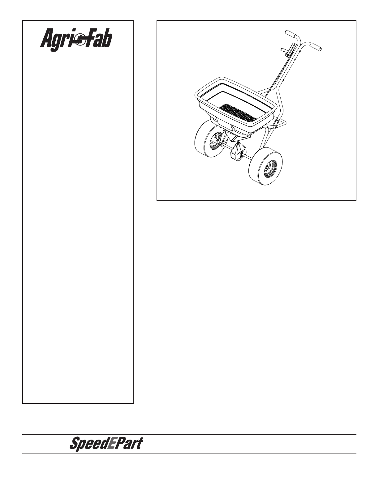
OwNERS MANUAL
Model No.
45-0382
45-0405
125 LB. PUSH
CAUTION:
Read Rules for
Safe Operation
and Instructions
Carefully
BROADCAST SPREADER
• Safety
• Assembly
• Operation
• Maintenance
• Parts
PRINTED IN USA
FORM NO. 49905 (REV. 11/06)
Page 2
RULES FOR SAFE OPERATION
6
2
1
7
4
3
8
5
The following precautions are suggested. This broadcast spreader is designed, engineered and tested to offer reasonably
safe and effective service, provided it is operated in strict accordance with these instructions. Failure to do so may result in
personal injury. Always observe the rules of safe operation.
LOOK FOR THIS SYMBOL TO POINT OUT IMPORTANT SAFETY PRECAUTIONS.
IT MEANS — ATTENTION! BECOME ALERT! YOUR SAFETY IS INVOLVED.
1. Do not allow anyone to operate the broadcast spreader without proper instructions.
2. Do not permit children to operate the broadcast spreader.
3. Wear eye and hand protection when handling and when applying lawn or garden chemicals.
4. Read the chemical label instructions and cautions for handling and applying the chemicals purchased for spreading.
5. Keep all nuts, bolts and screws tight to be sure equipment is in safe working condition.
6. Follow maintenance and lubrication instructions as outlined in this manual.
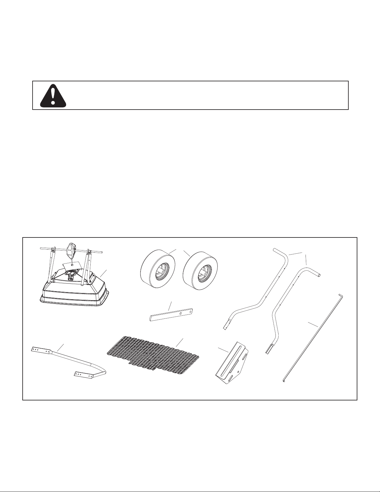
CARTON CONTENTS
LOOSE PARTS IN CARTON
1. Hopper Assembly
2. Wheels (2)
3. Flow Control Bracket
4. Flow Control Lever
5. Flow Control Rod
6. Upper Handle (2)
7. Stand
8. Hopper Screen
Hardware Package (Shown next page)
2
Page 3
FULL SIZE
H
I
J
A
C
K
E
F
G
L
M
N
O
P
Q
B
(Not Shown Full Size)
(Not Shown Full Size)
D
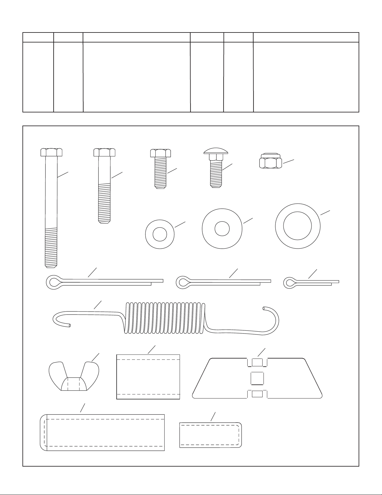
HARDwARE PACKAGE CONTENTS (Shown full size except where noted)
Key Qty. Description Key Qty. Description
A 3 Hex Bolt, 1/4-20 x 2-1/2 in. Long
B 8 Hex Bolt, 1/4-20 x 1-1/2 in. Long
C 1 Hex Bolt, 1/4-20 x 3/4 in. Long
D 1 Carr. Bolt,1/4-20 x 3/4 in. Long
E 12 Nylock Nut, 1/4-20
F 3 Washer, 1/4 in. SS
G 1 Washer, Nylon
H 6 Washer, 5/8 ID x 1 in. OD
I 1 Cotter Pin, 5/32 x 2 in.
J 2 Cotter Pin, 9/64 x 1-1/2 in.
K 1 Cotter Pin, 1/8 x 3/4 in.
L 1 Spring
M 1 Wing Nut, 1/4-20 Nylon
N 2 Spacer
O 1 Adjustable Stop
P 2 Handle Grip
Q 1 Flow Control Lever Grip
3
Page 4
ENGLISH
1/4-20 x 1-1/2 in.
HEX BOLT (B)
1/4-20 NYLOCK
NUT (E)
5/32 x 2 in.
COTTER PIN (I)
9/64 x 1-1/2 in.
COTTER PIN (J)
5/8 in. FLAT
WASHER (H)
5/8 in. FLAT WASHER (H)
SPACER (N)
ASSEMBLY INSTRUCTIONS
TOOLS REQUIRED FOR ASSEMBLY
(1) Pliers
(2) 7/16 in. open or boxed end wrenches
1. Remove the spreader, the loose parts and the hardware
package from the carton. Lay out parts and hardware
and identify using the illustrations on pages 2 and 3.
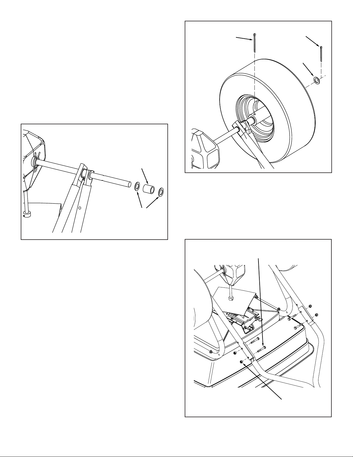
2. With the spreader resting upside down on the top of the
hopper, assemble a 5/8 in. at washer, a spacer and
a second 5/8 in. at washer onto each end of the axle.
See gure 1.
FIGURE 2
FIGURE 1
3. Place a wheel onto each end of the axle. The long end
of the hub goes to the inside. See gure 2.
4. Assemble a 5/32 x 2 in. cotter pin through the hole in
one wheel hub and the axle. See gure 2.
5. Place a 5/8 in. at washer onto each end of the
axle and secure with a 9/64 x 1-1/2 in. cotter pin.
See gure 2.
6. Install an upper handle to each lower handle using four
1/4 x 1-1/2 in. bolts and nylock nuts. Do not tighten at
this time. See gure 3.
FIGURE 3
4
Page 5

1/4-20 x 1-1/2 in.
HEX BOLT (B)
1/4-20 NYLOCK
NUT (E)
USE
MIDDLE
HOLE
USE THIS
HOLE
7. For the standard setup, use the holes shown in
1/4-20 x 2-1/2 in.
HEX BOLT (A)
1/4-20 NYLOCK
NUT (E)
1/4 in. WASHER (F)
SPRING (L)
1/8 in. HOLE
SPRING
ANCHOR
HOLE
FLOW
CONTROL
LINK
LEVER
LEVER
GRIP (Q)
1/4-20 NYLOCK
NUT (E)
1/4 in. NYLON
WASHER (G)
1/4-20 x 3/4 in.
HEX BOLT (C)
HANDLE
GRIP (P)
the illustration. Other hole combinations allow
different handle heights and hopper angles. Do
not use holes in stand that are farthest apart as a
combination - ow gate may not close completely.
Attach the stand to the hopper frame tube using two
1/4 x 1-1/2 in. bolts and nylock nuts. Attach the stand
to the lower handle using two 1/4 x 1-1/2 in. bolts and
nylock nuts. Tighten all four bolts to secure the stand.
See gure 4.
9. Install a handle grip on each handle. See gure 6.
10. Attach the ow control lever to the bracket using one
1/4 x 3/4 in. bolt, nylon washer and nylock nut. Tighten
carefully to allow the lever to move freely. Install the
vinyl grip. See gure 6.
FIGURE 4
8. Atta c h the two upper handl e s tog e ther with
the flow control bracket as shown using three
1/4 x 2-1/2 in. bolts and nylock nuts. Do not tighten
two bolts in ow control bracket. Tighten third bolt in
upper handles. See gure 5.
FIGURE 6
11. Attach the spring to the stainless steel pattern plate as
shown. Attach the opposite end of the spring to the 1/8
in. hole in the ow control rod. Rotate the end of the rod
into the ow control link. See gure 7.
FIGURE 5
FIGURE 7
5
Page 6

1/8 x 3/4 in.
COTTER PIN (K)
FLOW
CONTROL
ROD
FLOW
CONTROL
LEVER
POSITION 5
ADJUSTABLE
STOP
1/4 in. NYLOCK NUTS
12. Insert the end of the ow control rod through the slot in
ADJUSTABLE
STOP
OFF
ADJUSTABLE
STOP (O)
1/4-20 WING NUT (M)
1/4-20 x 3/4 in.
CARRIAGE BOLT (D)
1/4 in. WASHER (F)
the ow control mounting bracket and through the hole
in the ow control lever. Secure with a 1/8 in. x 3/4 in.
cotter pin. See gure 8.
FIGURE 8
14. Adjust the position of the ow control mounting bracket
(gures 10 and 11):
a. Set the adjustable stop at “5.” Latch the ow control
lever against the stop. Verify that the closure plate
has opened about halfway. See gure 10.
b. If closure plate is not open halfway, adjust the position
of the ow control mounting bracket until the closure
plate is open about halfway at “5” and still closed when
the lever is in the “OFF” position. Carefully tighten
the 1/4 in. nylock nuts. Do not deform the slots in the
ow control mounting bracket.
c. Push the ow control lever to the “OFF” position
and ensure the closure plate closes completely.
See gure 11.
13. Install the adjustable stop on the slot in the top of
the ow control mounting bracket. Secure with the
1/4 in. x 3/4 in. carriage bolt, a nylon washer, a 1/4 in.
at washer and the nylon wing nut. See gure 9.
FIGURE 9
FIGURE 10
FIGURE 11
6
Page 7

15. Place the hopper screen down into the hopper, sliding
HOPPER
SCREEN
THUMB SCREW
the ends into the clips in the hopper. The screen helps
break up clumpy material and prevents large clumps
from reaching the bottom of the hopper and clogging
the opening. See gure 12.
FIGURE 12
1. To adjust the ow to be heavier to the left side,
tighten the thumbscrew so the plate is pushed inward.
See gure 13
2. To adjust the ow to be heavier to the right side,
loosen the thumbscrew so the plate is pulled outwards.
See gure 13
FIGURE 13
16. Lubricate the spreader following the instructions in the
MAINTENANCE section on page 9.
OPERATION
HOw TO USE YOUR SPREADER
SETTING THE FLOw CONTROL
(Refer to gure 10 on page 6.)
1. Loosen the nylon wing nut, set the adjustable stop to
the desired ow rate setting and retighten the wing nut.
The higher the setting number, the wider the opening
in the bottom of the hopper.
2. Refer to the Application Chart on page 8 and to the
instructions on the fertilizer bag to select the proper
ow rate setting.
3. Pull the ow control lever back and latch to the adjustable
stop for the “ON” position. Unlatch and push toward the
hopper for the “OFF” position.
USING THE PATTERN ADJUSTMENT PLATE
The pattern adjustment plate is used to adjust the ow of
material being spread to the left or right side. The pattern
adjustment plate is located between the gate opening and
the spreader plate.
The adjustment of the pattern plate is sensitive and it is
recommended to test your spread pattern in a small area
rst.
USING YOUR SPREADER
The use of powdered lawn chemicals is not recommended,
due to difculty in obtaining a satisfactory or consistent
broadcast pattern.
1. Determine approximate square footage of area to be
covered and estimate amount of material required.
2. Before lling the hopper, make sure the ow control lever
is in the “OFF” position and the closure plate is shut.
3. Break up any lumpy fertilizer as you ll the hopper.
4. Set the adjustable stop with the ow control lever still
in the “OFF” position. Refer to the Application Chart on
page 8 and to the instructions on the fertilizer bag to
select the proper ow rate setting.
5. The Application Chart on page 8 is calculated for lightto-heavy application at a walking speed of 3 mph, or
100 ft. in 23 seconds. A variation in speed will require
an adjustment of the ow rate to maintain the same
coverage. The faster you walk, the wider the broadcast
width.
6. Always start the spreader in motion before opening the
closure plate.
7. Always shut the closure plate before turning or stopping
the spreader.
8. If fertilizer is accidentally deposited too heavily in a small
area, soak the area thoroughly with a garden hose or
sprinkler to prevent burning of the lawn.
7
Page 8

OVERLAP
8' to
10'
9. To insure uniform coverage, make each pass so that the
broadcast pattern slightly overlaps the pattern from the
previous pass as shown in gure 14. The approximate
broadcast widths for different materials are shown in
the Application Diagram gure 14.
IMPORTANT: Application rates shown in the chart are
affected by humidity and by the moisture content of
the material (granular and pellet). Some minor setting
adjustments may be necessary to compensate for this
condition.
10. When broadcasting weed control fertilizers, make sure
the broadcast pattern does not hit evergreen trees,
owers or shrubs.
APPLICATION DIAGRAM
FIGURE 14
APPLICATION CHART
MATERIAL
TYPE
FERTILIZER
Powder
Granular
Pelleted
Organic
GRASS SEED
Fine
Coarse
ICE MELTER
OPERATING SPEED - 3 MPH. (100 ft. in 23 seconds)
FLOW SETTING
3 MPH
(100 FT. IN 23 SEC.)
3-5
3-5
3-5
6-8
3-4
4-5
6-8
SPREAD
WIDTH IN
FEET
3-4
8-10
10-12
6-8
6-7
8-9
10-12
8
Page 9

MAINTENANCE
OIL
GREASE
HAIRPIN
HAIRPIN
SPROCKET
SHAFT
AGITATOR
HAIRPIN
CHECK FOR LOOSE FASTENERS
1. Before each use, make a thorough visual check of
the spreader for any bolts and nuts which may have
loosened. Retighten any loose bolts and nuts.
CHECK FOR wORN OR DAMAGED PARTS
2. Check for worn or damaged parts before each use.
Repair or replace parts if necessary.
CHECK TIRE INFLATION
3. Check if tires are adequately inated before each use.
Do not inate tires beyond maximum recommended
pressure on tire.
CAUTION: DO NOT inate tires beyond the
maximum recommended pressure printed
on side of tire.
CLEANING
4. Rinse inside of hopper and exterior of spreader and
allow to dry before storing.
LUBRICATE (See gure 15)
5. Remove one small and two large hairpins and separate
the gearbox housings.
6. Lightly apply automotive grease as needed to the
sprocket and gear.
7. Oil the nylon bushings on the vertical sprocket shaft.
Apply grease to the axle at least once a year, or more
often as needed.
8. Oil (idler) wheel at least once a year or more often as
needed.
9. Install gearbox housings and secure with hairpins.
FIGURE 15
STORAGE
1. Rinse inside of hopper and exterior of spreader and
allow to dry before storing.
2. Store in a clean, dry area.
SERVICE AND ADJUSTMENTS
1. If the axle and gear assembly is disassembled, mark
down the positions of the parts as they are removed.
The drive wheel and large gear positions, in relation
to the small gear, determine which direction the
spreader plate will spin. Be sure to reassemble them
in their original positions. (Refer to parts exploded
view on page 10). Ensure washer (Refer to item 25
on page 10 and 11) is in place when assembling the
axle components. Add grease to gears.
2. If the agitator hairpin becomes damaged or worn, it
can be replaced. Remove old agitator hairpin from
hole in sprocket shaft and replace with new agitator
hairpin. See gure 16.
FIGURE 16
9
Page 10

REPAIR PARTS FOR BROADCAST SPREADER
32
33
26
23
32
34
24
22
29
27
33
25
28
27
30
31
1
9
9
66
7
8
12
9
8
6
10
38
10
10
3
10
40
48
39
48
40
4242
4
3
54
25
36
25
35
4
2
10
5
21
21
5
39
25
35
4
54
25
36
15
49
50
16
11
14
10
13
19
17
20
18
37
10
7
10
46
44
47
45
41
52
20
6
43
7
55
53
39
4
25
56
MODEL 45-0382 AND 45-0405
10
Page 11

REPAIR PARTS FOR BROADCAST SPREADER
the fastest way to purchase parts
www.speedepart.com
MODEL 45-0382 AND 45-0405
Ref. Part Qty. Description
No. No.
1 44466 1 Hopper, Spreader (125 lb.)
2 48842 1 Tube, Frame (45-0382)
48842SS 1 Tube, Frame (45-0405)
3 25755 2 Handle, Lower (45-0382)
25755SS 2 Handle, Lower (45-0405)
4 741-0249 4 Bearing, Flanged
5 49910 2 Spacer, Axle Tube ss
6 1543-69 7 Washer, Nylon
7 49890 7 Washer, 1/4 in. Std. ss
8 25672 2 Clip
9 49892 6 Bolt, Hex 1/4-20 x 1-3/4 ss
10 49891 19 Nut, Hex 1/4-20 Nylock ss
11 65457 1 Weldment, Guide Closure
12 49894 4 Bolt, Slot Truss 10-32 x 1/2 in. ss
13 44285 1 Bushing, Hopper
14 49895 4 Hex Nut, 10-32 Nylock ss
15 25757 1 Pattern, Plate
16 23533 1 Closure, Plate
17 25917 1 Slide Gate Angle Bracket ss
18
19 25758 1 Link, Flow Control ss
20 40199 2 Bolt, Hex 1/4-20 x 3/4 in. ss
21 49798 2 Fitting. Grease 1/4 in.
22 25759 1 Shaft, Axle Spreader ss
23 47209 1 Gear, Large
24 47204 1 Yoke, Large
25 49899 7 Washer, Flat 5/8 in. ID x 1 in. OD
26 43659 1 Spring, Pin, 3/16 x 1 in.
27 46055 3 Spring, Pin 1/8 x 1 in.
28 49896 1 Shaft, Impeller ss
43882
2 Rivet, POP ss 3/16 in.
Ref. Part Qty. Description
No. No.
29 47205 1 Gear, Small
30 4367 1 Impeller
31 48934 1 Agitator, Hairpin
32 47212 2 Housing, Large Gear
33 49897 2 Hairpin, Clip Large
34 49898 1 Hairpin, Clip Small
35 49930 2 Spacer, Tube
36 49907 2 Wheel, Poly 5/8 in. ID x 13-5.00
37 49902 1 Flow Control Rod
38 25762 1 Tube Stand (45-0382)
25762SS 1 Tube Stand (45-0405)
39 49909 8 Bolt, Hex 1/4-20 x 1-1/2 in.
40 25761 2 Handle, Upper (45-0382)
25761SS 2 Handle, Upper (45-0405)
41 24855 1 Flow Control Bracket
42 49908 3 Bolt, Hex 1/4-20 x 2-1/2 in. ss
43 25760 1 Lever, Flow Control
44 43848 1 Grip, Control Arm
45 25763 1 Stop, Adjustable ss
46 49903 1 Bolt, Carr. 1/4-20 x 3/4 in.
47 47141 1 Nut, Wing 1/4-20 Nylon
48 49904 2 Grip, Handle
49 49931 1 Screw, Thumb 1/4-20 x 1-1/4 in.
50 49901 1 Spring, ss
52 142 1 Pin, Cotter 1/8 x 3/4 in.
53 40249 1 Pin, Cotter 5/32 x 2 in.
54 49911 2 Pin, Cotter 9/64 x 1-1/2 in.
55 47441 1 Screen, Spreader
56 40520 1 Nut, Nylon
49905 1 Owners Manual (Not Shown)
11
Page 12

© 2006 Agri-Fab, Inc.
the fastest way to purchase parts
www.speedepart.com
REPAIR PARTS
Agri-Fab, Inc.
809 South Hamilton
Sullivan, IL 61951
217-728-8388
www.agri-fab.com
 Loading...