

Page 1
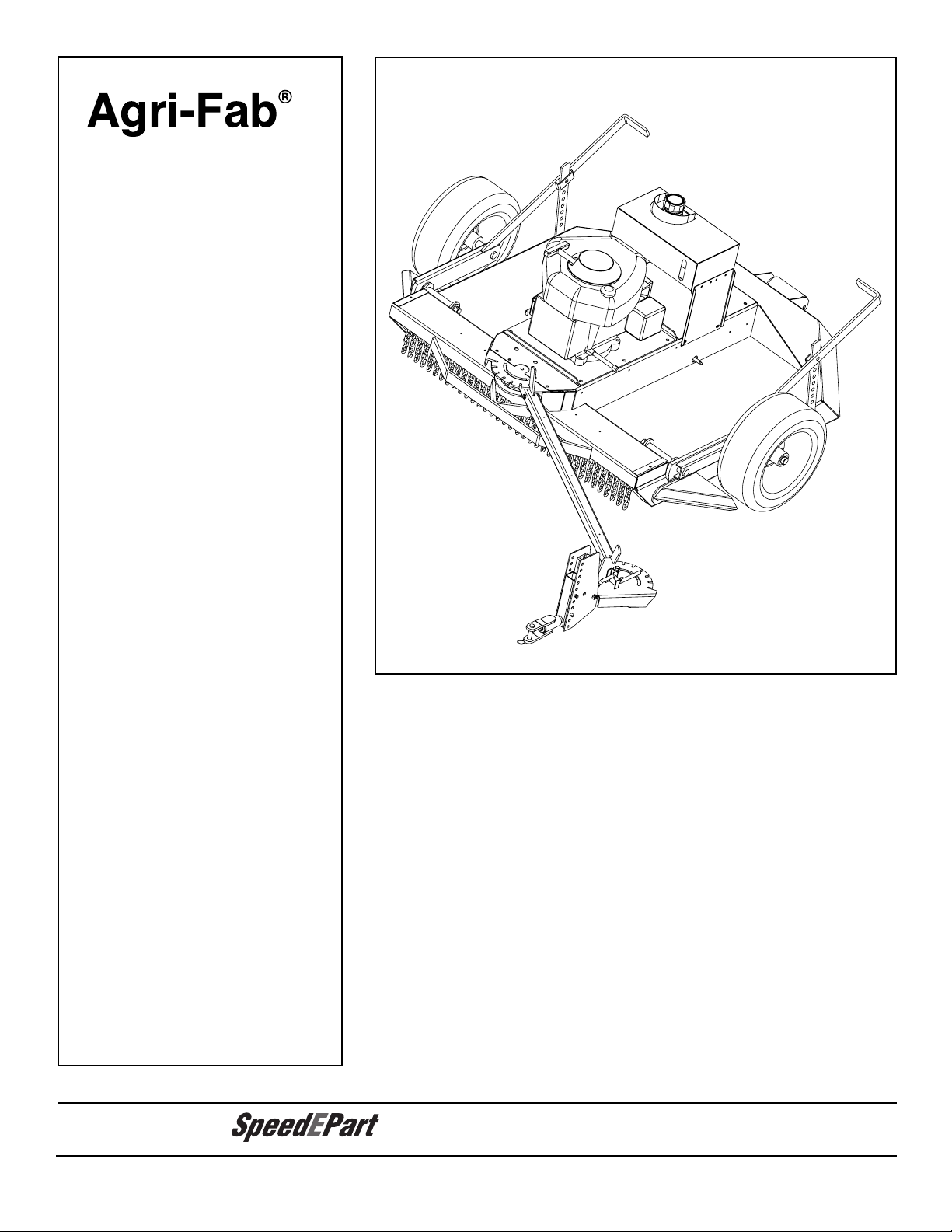
Agri-Fab
OWNERS
MANUAL
Model No.
45-03072
45-03611
¨
42" ROUGH CUT
CAUTION:
Read Rules for
Safe Operation
and Instructions
• Safety
Carefully
• Assembly
• Operation
• Maintenance
• Parts
the fastest way to purchase parts
PRINTED IN U.S.A. FORM NO. 49464 (5/04)
TRAILMOWER
www.speedepart.com
Page 2

TABLE OF CONTENTS
SAFETY RULES ...................................................... 3,4
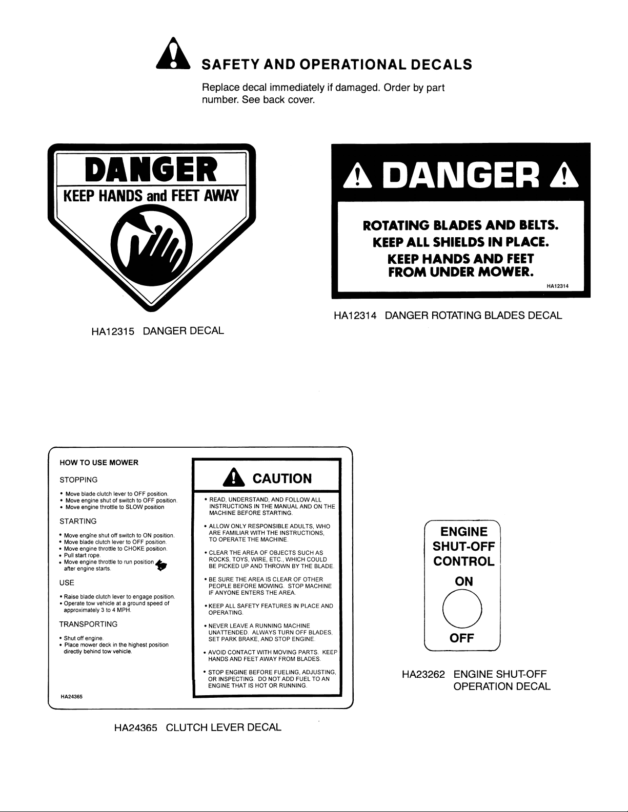
SAFETY AND OPERATIONAL DECALS ................ 5,6
HARDWARE CHART .................................................. 7
ASSEMBLY ............................................................ 8-11
OPERATION ......................................................... 12-16
CUSTOMER RESPONSIBILITIES...................... 17-20
STORAGE ................................................................. 21
REPAIR PARTS ................................................... 22-26
WIRING DIAGRAM ................................................... 27
2
Page 3

34567
Page 4
Page 5
Page 6

Page 7
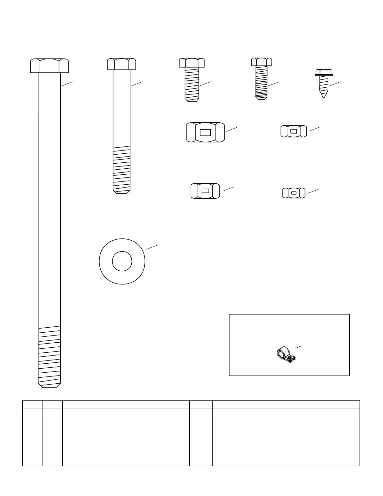
CONTENTS OF PARTS BAG
SHOWN FULL SIZE
A B C D E
F
G
J
H
I
REF. QTY. DESCRIPTION
A 1 Hex Bolt, 1/2" x 7"
B 2 Hex Bolt, 3/8" x 2-3/4"
C 2 Hex Bolt, 5/16" x 3/4"
D 1 Hex Bolt, 1/4" x 3/4"
E 3 Screw, Self Tapping #10 x 1/2"
F 1 Hex Lock Nut, 1/2"
NOT SHOWN FULL SIZE
K
REF. QTY. DESCRIPTION
G 2 Hex Lock Nut, 3/8"
H 2 Hex Lock Nut, 5/16"
I 1 Hex Lock Nut, 1/4"
J 2 Flat Washer, 3/8"
K 3 Clip, 3/8"
Page 8
ASSEMBLY
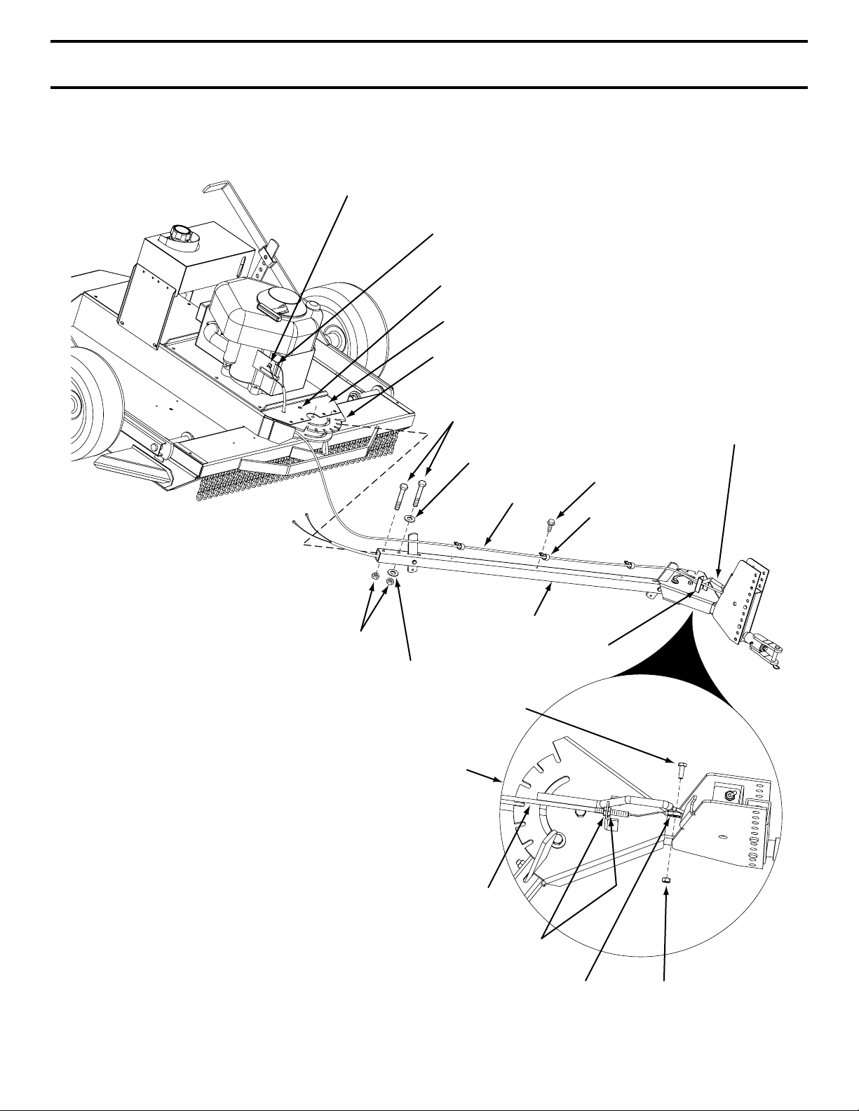
INSTALL WIRE HARNESS TO ENGINE
• Feed Wire Harness up through hole in middle of Front
Drive Cover.
• Install one Wire to Engine Magneto Ground Terminal.
(The same Terminal as red Wire from inside Mower.)
• Install other Wire of Wire Harness to Engine Ground
Base. (The same Terminal as black Wire from inside
Mower.)
• Refasten Front Drive Cover to mower housing.
INSTALL CLUTCH TO TOWBAR TUBE
• Place Clutch Cable forward along Towbar Tube.
• Spread ends of three Cable Clips and place around
Clutch Cable.
• Place Clutch Cable on top of Towbar Tube and align
Cable Clips with bolt holes in Towbar Tube.
• Secure with three #10 Screws.
INSTALL TOWBAR TUBE TO REAR
QUADRANT
• Remove Hex Bolts and lift Front Drive Cover from
mower housing.
• Rest end of Tow Bar Tube on front edge of mower.
• Feed Wire Harness in end of Tow Bar Tube through
large hole in back wall of Rear Quadrant.
• Place Towbar Tube into Rear Quadrant, align holes
and insert 3/8 x 2-3/4 Hex Bolt through quadrant
and rear hole of Tube.
• Secure tightly with 3/8 Hex Lock Nut and then
loosen 1/4 turn to allow Tube to pivot freely inside
Rear Quadrant.
• Assemble a 3/8 Flat Washer onto a 3/8 x 2-3/4 Hex
Bolt.
• Insert Bolt and Washer into slot in Rear Quadrant
and into hole in Towbar Tube.
• Secure Tightly with 3/8 Flat Washer and 3/8 Hex
Lock Nut, then loosen 1/4 turn to allow Tube to
pivot freely inside Rear Quadrant.
NOTE: Towbar Tube must pivot freely inside Rear
Quadrant when Latch is pulled from notch.
8
Page 9
ASSEMBLY
ENGINE MAGNETO GROUND (RED WIRE)
ENGINE GROUND BASE
FEED WIRE HARNESS
THROUGH THIS HOLE
FRONT DRIVE COVER
REAR QUADRANT
3/8 X 2-3/4 HEX BOLT
3/8 FLAT WASHER
CLUTCH CABLE
#10 SCREW (3)
CABLE CLIPS (3)
CLUTCH LEVER
FIG. 1
3/8 HEX LOCK NUT
3/8 FLAT WASHER
HITCH ASSEMBLY
TOW BAR TUBE
1/4 X 3/4 HEX BOLT
CLUTCH CABLE
5/16 HEX NUT (2)
MOUNTING ANCHOR
CABLE GUIDE
1/4" HEX LOCK NUT
9
Page 10

ASSEMBLY
SWITCH
BODY
INNER NUT
OUTER NUT
CLUTCH CABLE ADJUSTMENT
• Remove four screws from Rear Drive Cover. Lay aside
cover and screws.
• Place Clutch Lever in "DISENGAGED" position
• The Cable should be under slight tension but should
not pull the Clutch Lever more than 1/8" away from
the Switch Body.
NOTE: If the Plunger extends more than 1/8" out from
the switch body, the cable tension is too tight and the
Engine will not start.
TO INCREASE CABLE TENSION
• Place Blade Clutch Lever in the "DISENGAGED"
position.
• Loosen the inner nut on the Clutch Cable.
• Tighten the outer nut on the Clutch Cable.
TO DECREASE CABLE TENSION
• Place Blade Clutch Lever in the "DISENGAGED"
position.
• Loosen the outer nut on the Clutch Cable.
• Tighten the inner nut on the Clutch Cable.
• Repeat the above procedure until you have the
correct tension.
1/8"
PLUNGER
CLUTCH LEVER
REAR DRIVE
COVER
FIG. 2
FOUR
SCREWS
ENGINE
PULLEY
BLADE
PULLEY
10
IDLER
PULLEY
CLUTCH LEVER
Page 11

ASSEMBLY
INSTALL REAR ROLLER TO DECK
• Install Rear Roller Mounting Bracket to rear of deck
using two 5/16 x 3/4 Hex Bolts and two 5/16 Hex
Lock Nuts. (See Fig. 3.)
• Install Roller to Rear Roller Bracket using 1/2 x 7
Hex Bolt and 1/2 Hex Lock Nut.
• Make sure Roller turns freely on Bolt.
5/16 X 3/4 HEX BOLTS
AND 5/16 HEX LOCK NUTS
ROLLER
1/2 X 7 HEX BOLT
REAR ROLLER
MOUNTING BRACKET
1/2 HEX LOCK NUT
FIG. 3
11
Page 12

OPERATION
HEIGHT ADJUSTMENT STRAP
HEIGHT ADJUSTMENT
LIFT LEVER
RECOIL START HANDLE
MOWER BLADE
CLUTCH LEVER
SHUT OFF
CONTROL
TOW HITCH OFFSET
ADJUSTMENT
TOW BAR HEIGHT
ADJUSTMENT
FIG. 4
12
Page 13

OPERATION
13
Page 14

OPERATION
HAIR COTTER PIN
TOW BAR
ADJUSTMENT
HAIR COTTER PIN
LOCATING PIN
CLEVIS PIN
TOW BAR
GROUND LEVEL
HEIGHT ADJUSTMENT STRAP
HEIGHT ADJUSTMENT
LIFT LEVER
CUTTING
HEIGHTS
1-1/2"
2"
2-1/2"
3"
3-1/2"
4"
4-1/2"
5"
CUTTING HEIGHT
FIG. 6
14
Page 15

OPERATION
This mower has been designed to run offset from the
center of the tow vehicle. This allows the operator to
drive along side high brush with the tow vehicle while
cutting down the brush beside him. The adjustable
hitch gives you three offset cutting positions plus
straight behind for narrow paths.
MODEL 45-03071
The adjustable hitch of this mower can be set in seven
positions including straight and offsets of 15", 29" and
39" on both sides.
MODEL 45-0361
The adjustable hitch of this mower can be set in seven
positions including straight and offsets of 9", 17" and
23" on both sides.
15
Page 16

OPERATION
16
Page 17

CUSTOMER RESPONSIBILITIES
WHEEL 2
SWIVEL 2
17
WHEEL PIVOT 3
QUADRANT 3
WHEEL PIVOT 3
SPINDLE 2
WHEEL 2
Page 18

CUSTOMER RESPONSIBILITIES
BLADE CARE AND SERVICE
CAUTION:
DO NOT HANDLE MOWER BLADES WITH
BARE HANDS. CARELESS OR IMPROPER
HANDLING MAY RESULT IN SERIOUS
INJURY.
BLADE CARE
For best results mower blades must be kept sharp. The
blades can be sharpened with a file or on a grinding
wheel. Do not attempt to sharpen blades while they are
still on the mower.
BLADE SERVICE (Refer to fig. 9)
TO REMOVE BLADE ASSEMBLY FROM DECK
• Remove cotter pin from the spindle shaft.
• Remove nut and washer from the spindle shaft.
• Pull blade assembly off the spindle shaft. (Watch for
a key in the spindle shaft.)
TO REMOVE BLADES FROM BLADE ASSEMBLY.
• Remove cotter pin from the blade bolt.
• Remove nut from the blade bolt.
• Remove blade from the blade assembly.
BLADE SHARPENING
• Blades can be sharpened with a file or grinding wheel.
NOTE: When sharpening blades take care to maintain
blade balance. Sharpen both blades equally even if one
blade does not need to be sharpened. Check balance by
weighing each blade to make sure they are equal in weight.
BLADE ASSEMBLY
FIG. 9
WARNING:
SHUT OFF MOWER ENGINE AND REMOVE
SPARK PLUG WIRE FROM SPARK PLUG
BEFORE MAKING ANY ADJUSTMENTS OR
REPAIRS TO THE MOWER.
CLEANING THE MOWER
Water pressure from a garden hose will remove fresh
clippings from the underside of the mower. Clean mower
after each mowing.
CAUTION:
IF YOUR BLADE BOLTS SHOW WEAR,
REPLACE THEM WITH FACTORY
REPLACEMENTS ONLY.
TO REINSTALL BLADES
• Assemble a blade bolt through a flat washer, a blade
and then another flat washer.
• Assemble the bolt through the hole in the stump
plate and the blade hub assembly.
• Assemble a flat washer and nut onto the blade bolt.
• Tighten nut, then loosen just until blade can pivot.
• Install a cotter pin to secure the nut.
TO REINSTALL BLADE ASSEMBLY TO MOWER
• Reinstall key in spindle shaft, if necessary.
• Install the blade assembly onto the spindle shaft.
• Secure with flat washer and nut.
• Torque the spindle shaft and nut to 15 FT. LBS. and
secure with a hair cotter pin.
DAILY MAINTENANCE
Make sure all nuts and bolts are tight, cotter pins and
retainer springs are secure. Keep blades sharp. Observe
all Safety Precautions. Keep mower well lubricated.
REPAIR PARTS
Your rotary mower has been produced with components
designed for your unit. Although standard V-belts,
bearings, blades, pulleys, etc. may look like parts used
on your rotary mower, while similar in appearance many
are of a different construction and could in some cases
cause a malfunction in the operation of the machine.
For continued satisfactory performance use only repair
parts supplied by the manufacturer. See the dealer
where the mower was purchased for factory replacement
parts.
18
Page 19

CUSTOMER RESPONSIBILITIES
SWITCH
BODY
INNER NUT
OUTER NUT
CLUTCH CABLE ADJUSTMENT
• Remove four screws from Rear Drive Cover. Lay aside
cover and screws.
• Place Clutch Lever in "DISENGAGED" position
• The Cable should be under slight tension but should
not pull the Clutch Lever more than 1/8" away from
the Switch Body.
NOTE: If the Plunger extends more than 1/8" out from
the switch body, the cable tension is too tight and the
Engine will not start.
TO INCREASE CABLE TENSION
• Place Blade Clutch Lever in the "DISENGAGED"
position.
• Loosen the inner nut on the Clutch Cable.
• Tighten the outer nut on the Clutch Cable.
TO DECREASE CABLE TENSION
• Place Blade Clutch Lever in the "DISENGAGED"
position.
• Loosen the outer nut on the Clutch Cable.
• Tighten the inner nut on the Clutch Cable.
• Repeat the above procedure until you have the
correct tension.
CL
•
•
•
NO
the
Eng
TO
•
•
•
TO
•
•
•
•
1/8"
PLUNGER
CLUTCH LEVER
REAR DRIVE
COVER
FOUR
SCREWS
ENGINE
PULLEY
BLADE
PULLEY
19
IDLER
PULLEY
CLUTCH LEVER
Page 20

CUSTOMER RESPONSIBILITIES
V-BELT REPLACEMENT
• V-belt must be replaced if it becomes stretched to
the point that it can no longer be adjusted, or if it
becomes frayed or otherwise can not function
properly.
• Move Blade Clutch Lever to the "DISENGAGED"
position.
CAUTION:
DISCONNECT SPARK PLUG WIRE
REMOVING OLD V-BELT
• Remove Rear Drive Cover.
• Remove Front Drive Cover.
• Remove Hair Pin and Clevis Pin from Clutch Cable.
• Loosen two Rear Belt Guides and pivot them away
from Blade Pulley.
• Remove V-belt from around Blade Pulley.
• Remove one small Hair Pin from Belt Keeper Rod
and slide Belt Keeper Rod to the side.
• Pull V-belt down from around Engine Pulley and
remove V-belt from Mower.
INSTALLING NEW V-BELT
• Feed new V-belt between the two belt guides at the
Engine Pulley.
• Place V-belt up and around the Engine Pulley. Check
to make sure the V-belt is seated properly in the
groove of the Engine Pulley.
• Place V-belt along inside of Idler Pulley.
• Wrap V-belt down around Blade Pulley, placing Belt
inside of Rear Belt Guides.
• Reinstall V-belt Keeper Rod and secure with Small
Hair Pin. Check to make sure V-belt is over top of
Keeper Rod.
• Reposition and retighten two Rear Belt Guides at the
rear of the Blade Pulley. Leave approximately 1/16"
between Guides and Pulley.
• Reinstall Clevis Pin and Hair Pin into Clutch Cable.
• Reinstall Front Drive Cover and Rear Drive Cover.
ENGINE PULLEY
BELT GUIDES
HAIRPIN AND CLEVIS PIN
BLADE PULLEY
REAR BELT GUIDES
BELT KEEPER ROD V-BELT
20
Page 21

STORAGE
21
Page 22

42" ROUGH CUT TRAILMOWER - MODELS 45-03072 & 45-03611
22
Page 23

42" ROUGH CUT TRAILMOWER - MODELS 45-03072 & 45-03611
ITEM PART NO. DESCRIPTION
1. HA24255 MOWER DECK
2. HA24378 GUARD WHEEL
3. HA23193 SCREW 3/8-16 X 1-1/4 THD. FORMING
4. HA24292 BRACKET BELT GUIDE
5. HA24293 ROD BELT GUIDE
6. HA3090 PIN HAIR COTTER
7. HA24294 V-BELT (B SEC. 60" O.C.)
8. HA24295 CHANNEL CLUTCH LEVER
9. 45100 BOLT 1/2-13 X 4" HEX HEAD
10. HA120396 WASHER 1/2 FLAT
11. 43262 NUT 1/2-13 HEX LOCK
12. HA14232 WASHER FLAT
13. HA24296 ROD CLUTCH LINK
14. 44101 PIN, COTTER 3/32" X 3/4"
15. 43081 WASHER FLAT 5/16" STD. WRT.
16. HA24297 SPRING CLUTCH
17. HA24617 CLUTCH CABLE ASSY (Model 45-03071)
49165 CLUTCH CABLE ASSY (Model 45-0361)
18. 25292 STRAP, CLUTCH ADJUSTING
19. 43661 BOLT, 1/4-20 X 1" HEX HEAD
20. 43016 NUT 1/4-20 HEX LOCK
21. 25262 BRACKET INTERLOCK MOUNTING
22. HA23199 SWITCH INTERLOCK
23. 64904 MODULE ASSY WITH WIRES
24. 712-0121 NUT #10-24 HEX
25. 47078 SCREW #10-24 X 3/4"
26. 48840 SCREW 1/4-20 WASHER HEAD
27. 48298 CLIP, CORD
28. HA24300 WHEEL MOUNTING BRACKET L.H.
29. HA24301 WHEEL MOUNTING BRACKET R.H.
30. HA4143 WASHER FLAT
31. HA137258 PIN COTTER 3/16" X 1-3/4"
32. HA24308 TIRE
33. HA23229 CAP HUB
34. HA24309 STRAP ADJUSTING
35. HA6979 WASHER FLAT
36. 43020 BOLT 1/2-13 X 1-1/2 HEX HEAD
37. 43019 NUT 1/2-13 HEX JAM
38. HA23220 PIN LOCATING
39. 47134 PIN HAIR COTTER .08" X 1.58"
40. HA24311 CHAIN DEFLECTOR
ITEM PART NO. DESCRIPTION
41. HA24312 ROD CHAIN
42. HA24313 BRACKET CHANNEL
43. HA9131 SCREW SELF THREADING
44. 25428 PLATE ENGINE MOUNTING
45. 49161* ENGINE, 11 HP
46. HA24457 PULLEY
47. HA3073 KEY 1/4" SQ. X 1"
48. HA115321 SCREW 5/16-18 X 5/16 SOC. SET
50. 43555 WASHER 7/16" LOCK
51. HA181668 BOLT 7/16-20 X 1-1/4 HEX HEAD
52. 25051 COVER, GAS TANK
53. 25265 COVER, FRONT DRIVE
55. 43182 BOLT 5/16-18 X 3/4 HEX HEAD
56. 43064 NUT 5/16-18 HEX LOCK
57. 25264 COVER, REAR DRIVE
58. HA23732 TANK GASOLINE
59. HA24317 PLATE FUEL TANK
60. HA163318 SCREW 1/4-14 X 7/8 TAPPING PAN HEAD
61. HA23733 CAP GASOLINE TANK
62. 48837 HOSE FUEL TANK LONG
63. HA24455 HOSE FUEL TANK SHORT
64. HA23792 CLAMP FUEL LINE
65. HA23791 FILTER FUEL LINE
66. 48095 PIPE
67. 48096 CAP
68. HA24310 BRACKET ROLLER
69. HA12138 ROLLER MOWER
70. HA12315 DECAL DANGER (HAND)
71. HA12314 DECAL DANGER
72. HA24365 DECAL OPERATION/CAUTION
73. HA24366 DECAL HEIGHT ADJUSTMENT
74. HA126145 BOLT 1/2-13 X 7" HEX HEAD
75. 43982 PIN, CLEVIS 1/4" X 5/8"
76. HA22981 BELT GUIDE
77. HA24298 SPRING RETURN
78. 49156 ROD, CABLE GUIDE
79 43013 NUT 1/4-20 HEX
80. 44488 WHEEL BEARING
* Order engine repair parts from your nearest Briggs & Stratton
dealer.
the fastest way to purchase parts
23
www.speedepart.com
Page 24

42" ROUGH CUT TRAILMOWER - MODELS 45-03072 & 45-03611
9
11
12
6
5
4
3
1
20
18
33
32
18
21
19
23
4
8
7
2
18
13
14
15
24
23
34
21
22
25
22
25
16
17
30
31
28
24
37
6
5
4
36
35
38
6
15
27
28
29
25
26
28
27
28
24
Page 25

42" ROUGH CUT TRAILMOWER - MODELS 45-03072 & 45-03611
ITEM PART NO. DESCRIPTION
1. 64906 IDLER MOUNTING BRACKET
2. 64899 IDLER ARM
3. 24472 BUSHING
4. 43070 WASHER FLAT
5. 43003 WASHER 3/8" LOCK
6. 43062 BOLT 3/8-16 X 1-1/2" HEX HEAD
7. 49148 SPACER
8. HA21341 IDLER PULLEY (FLAT)
9. 43054 BOLT 3/8-16 X 2" HEX HEAD
10. 43082 NUT 3/8-16 HEX LOCK
11. HA22981 GUIDE BELT
12. HA22224 SCREW 3/8-16 X 3/4 SELF TAPPING
13. 43087 BOLT 3/8-16 X 1-1/4" HEX HEAD
14. HA15200 WASHER FLAT
15. HA21362 NUT 3/8-16 NYLOCK
16. HA24367 GREASE FITTING
17. HA24278 HUB (WITH STUDS)
18. HA24280 BEARING
19. 64913 HUB BLADE
20. 49148 SHAFT SPINDLE
21. HA24282 SEAL O-RING
22. HA3073 KEY 1/4" SQ X 1"
23. HA456151 WASHER 13/16 X 1-1/2 X .134 FLAT
24. HA427639 NUT 3/4-16 SLOTTED HEX
25. 43010 PIN 1/8" X 1" COTTER
26. HA24624 DISC BLADE MOUNTING
27. HA24288 BLADE
28. HA24625 WASHER - FLAT
29. HA24592 BOLT - 7/8-9 X 2-1/4 HEX BOLT
30. HA137258 PIN 3/16 X 1-3/4 COTTER
31. HA24593 NUT 7/8-9 SLOTTED HEX
32. 43353 WASHER 1/2 MED. LOCK
33. HA120371 NUT 1/2-20 HEX
34. 65102 PULLEY, SPINDLE
35. 64902 BRAKE
36. 49155 TRUNNION
37. 49160 BRAKE ROD
38. HA20186 SPRING
the fastest way to purchase parts
25
www.speedepart.com
Page 26

42" ROUGH CUT TRAILMOWER - MODELS 45-03072 & 45-03611
ITEM PART NO. DESCRIPTION
1. 25273 TUBE DRAWBAR (MODEL 45-0361)
HA24321 TUBE DRAWBAR (MODEL 45-03071)
2. HA24441 STRAP HITCH
3. HA20186 SPRING EXTENSION
4. 44180 BOLT 5/16-18 X 2" HEX HEAD
5. 43064 NUT 5/16-18 HEX LOCK
6. 64909 HITCH ASSEMBLY
7. HA180132 BOLT 3/8-16 X 2-1/4 HEX HEAD
8. 43509 BOLT 3/8-16 X 2-3/4 HEX HEAD
9. 43070 WASHER 3/8 FLAT
10. 43082 NUT 3/8-16 HEX LOCK
11. HA23636 PIN CLEVIS
12. 47134 PIN HAIR COTTER .08 X 1.58
13. 49157 LEVER CLUTCH
14. 43062 BOLT 3/8-16 X 1-1/2 HEX HEAD
15. HA19445 SPRING COMPRESSION
16. 43012 BOLT 1/4-20 X 3/4 HEX HEAD
the fastest way to purchase parts
ITEM PART NO. DESCRIPTION
17. 43013 NUT 1/4-20 LOCK
18. HA23262 DECAL ENGINE SHUT-OFF
19. HA23265 DECAL CLUTCH LEVER
20. 64910 BRACKET DRAWBAR ADJUSTMENT
21. HA24326 DRAWBAR SWIVEL
22. HA5074 FITTING GREASE
23. HA15200 WASHER
24. 43003 WASHER 3/8 LOCK
25. 43087 BOLT 3/8-16 X 1-1/4 HEX HEAD
26. HA24330 PIN CLEVIS
27. HA3341 PIN HAIR COTTER, 5/32"
28. HA22759 SWITCH ON/OFF
29. HA23761 CLIP HOSE 3/8"
30. HA9411666 SCREW #10-16 X 1/2 SELF TAPPING
31. 49164 WIRE HARNESS (MODEL 45-0361)
HA24353 WIRE HARNESS (MODEL 45-03071)
www.speedepart.com
26
Page 27

WIRING DIAGRAM
SWITCH
BLACK WIRE
FROM MODULE TO
ENGINE GROUND
BLACK WIRE
FROM ON/OF SWITCH
TO MAGNETO GROUND
ENGINE ON/OFF SWITCH
BLACK WIRE
FROM ON/OFF SWITCH
TO ENGINE GROUND
OIL
ENGINE
BLACK WIRE
FROM MODULE
TO SWITCH
RED WIRE FROM MODULE
TO MAGNETO GROUND
BLACK WIRE
FROM MODULE
TO SWITCH
A B C D E F
ELECTRONIC
CONTROL
MODULE
27
Page 28

© 2004 Agri-Fab, Inc.
the fastest way to purchase parts
REPAIR PARTS
Agri-Fab, Inc.
303 West Raymond
Sullivan, IL. 61951
217-728-8388
www.agri-fab.com
www.speedepart.com
 Loading...