

Agri-Fab 45-0353 Owner’s Manual
Agri-Fab ®
OWNER'S
MANUAL
Model No.
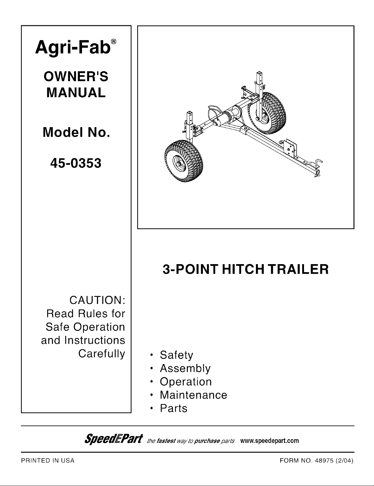
45-0353
CAUTION:
Read Rules for
Safe Operation
and Instructions
Carefully
3-POINT HITCH TRAILER
• Safety
• Assembly
• Operation
• Maintenance
• Parts
www.speedepart.com
PRINTED IN USA
FORM NO. 48975 (2/04)
SAFETY RULES
Remember, any power equipment can cause injury if operated improperly or if the user does not understand how to
operate the equipment. Exercise caution at all times when using power equipment.
CAUTION: VEHICLE BRAKING AND
IMPORTANT SAFETY PRECAUTIONS. IT
MEANS - ATTENTION! BECOME ALERT!
LOOK FOR THIS SYMBOL TO POINT OUT
YOUR SAFETY IS INVOLVED.
&
STABILITY MAY BE AFFECTED BYTHE
ADDITION OFAN ACCESSORY OR AN
ATTACHMENT. BE AWARE OF CHANG-
ING CONDITIONS ON SLOPES.
1. Read this owner's manual and your vehicle's
owner's manual before using this equipment.
2. Do not allow children to operate the vehicle, the
hitch trailer, or any implement attached to the hitch
trailer.
3. Do not allow adults to operate the vehicle, the hitch
trailer, or implement without proper instruction.
4. Do not allow anyone to ride on the hitch trailer or
attached implement.
5. Before lowering any implement attached to the
hitch trailer, make sure no one is near the area of
operation.
6. Lower any implement attached to the hitch trailer
when leaving the vehicle unattended.
7. Wear appropriate footwear when using the hitch
trailer. Implement attachments have sharp edges!
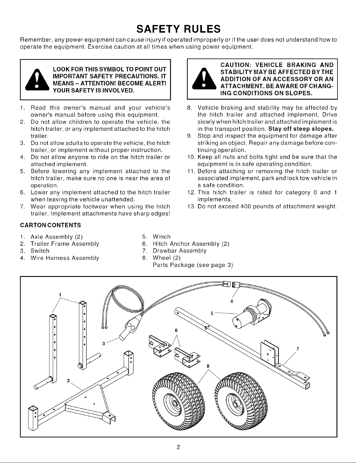
CARTONCONTENTS
1. Axle Assembly (2)
2. Trailer Frame Assembly
3. Switch
4. Wire Harness Assembly
5. Winch
6. Hitch Anchor Assembly (2)
7. Drawbar Assembly
8. Wheel (2)
Parts Package (see page 3)
8. Vehicle braking and stability may be affected by
the hitch trailer and attached implement. Drive
slowly when hitch trailer and attached implement is
in the transport position. Stay off steep slopes.
9. Stop and inspect the equipment for damage after
striking an object. Repair any damage before con-
tinuing operation.
10. Keep all nuts and bolts tight and be sure that the
equipment is in safe operating condition.
11. Before attaching or removing the hitch trailer or
associated implement, park and lock tow vehicle in
a safe condition.
12. This hitch trailer is rated for category 0 and 1
implements.
13. Do not exceed 400 pounds of attachment weight.
4
SHOWN FULL SIZE
I ---
/
CCP
/
F
/
M
I
O
H
/
NOT SHOWN FULL SIZE
R
/
/s
U
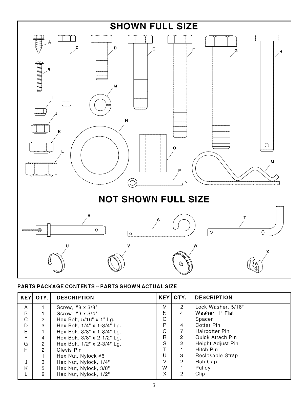
PARTS PACKAGE CONTENTS - PARTS SHOWN ACTUAL SIZE
KEY QTY. DESCRIPTION KEY
A 1 Screw, #8 x 3/8" M
B 1 Screw, #6 x 3/4" N
C 2 Hex Bolt, 5/16" x 1" Lg. 0
D 3 Hex Bolt, 1/4" x 1-3/4" Lg. P
E 1 Hex Bolt, 3/8" x 1-3/4" Lg. Q
F 4 Hex Bolt, 3/8" x 2-1/2" Lg. R
G 2 Hex Bolt, 1/2" x 2-3/4" Lg. S
H 2 Clevis Pin T
I 1 Hex Nut, Nylock #6 U
J 3 Hex Nut, Nylock, 1/4" V
K 5 Hex Nut, Nylock, 3/8" W
L 2 Hex Nut, Nylock, 1/2" X
V W
QTY.
2
4
1
4
7
2
2
1
3
2
1
2
_O
DESCRIPTION
Lock Washer, 5/16"
Washer, 1" Flat
Spacer
Cotter Pin
Haircotter Pin
Quick Attach Pin
Height Adjust Pin
Hitch Pin
Reclosable Strap
Hub Cap
Pulley
Clip
/
t
0
X
ASSEMBLY
TOOLS REQUIRED FOR ASSEMBLY
(2)
(1)
(2)
(2)
(1)
(1)
Remove all loose parts and the hardware package
from the shipping carton. Lay out and identify each
part and the common hardware as shown on pages 2
and 3. Be sure the carton is empty before discarding.
1 .
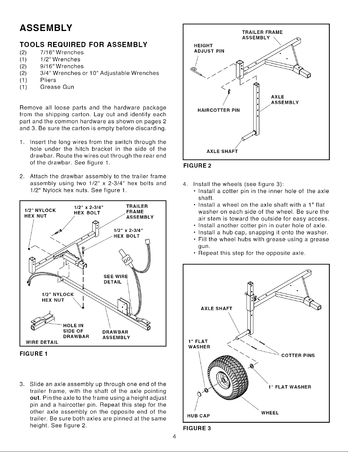
2. Attach the drawbar assembly to the trailer frame
7/1 6" Wrenches
1/2" Wrenches
9/1 6" Wrenches
3/4" Wrenches or 10" Adjustable Wrenches
Pliers
Grease Gun
Insert the long wires from the switch through the
hole under the hitch bracket in the side of the
drawbar. Route the wires out through the rear end
of the drawbar. See figure 1.
assembly using two 1/2" x 2-3/4" hex bolts and
1/2" Nylock hex nuts. See figure 1.
1/2" NYLOCK
112" x 2-314" TRAILER
HEX BOLT FRAME
HEX.UT
l 112" x 2-3/4"
HEX BOLT
TRAILER FRAME
ASSEMBLY
HEIGHT
ADJUST PIN
/
/
HAIRCOTTER PIN
/
/ i
AXLE
ASSEMBLY
J
/
AXLE SHAFT
FIGURE 2
4.
Install the wheels (see figure 3):
• Install a cotter pin in the inner hole of the axle
shaft.
• Install a wheel on the axle shaft with a 1" flat
washer on each side of the wheel. Be sure the
air stem is toward the outside for easy access.
• Install another cotter pin in outer hole of axle.
• Install a hub cap, snapping it onto the washer.
• Fill the wheel hubs with grease using a grease
gun.
• Repeat this step for the opposite axle.
112" NYLOCK
HEX NUT '_
HOLE IN
SIDE OF DRAWBAR
WIRE DETAIL
DRAWBAR ASSEMBLY
FIGURE 1
.
Slide an axle assembly up through one end of the
trailer frame, with the shaft of the axle pointing
out. Pin the axle to the frame using a height adjust
pin and a haircotter pin. Repeat this step for the
other axle assembly on the opposite end of the
trailer. Be sure both axles are pinned at the same
height. See figure 2.
AXLE SHAFT
1" FLAT
WASHER
HUB CAP
FIGURE 3
-_ COTTER PINS
/
1" FLAT WASHER
WHEEL
 Loading...