

Page 1
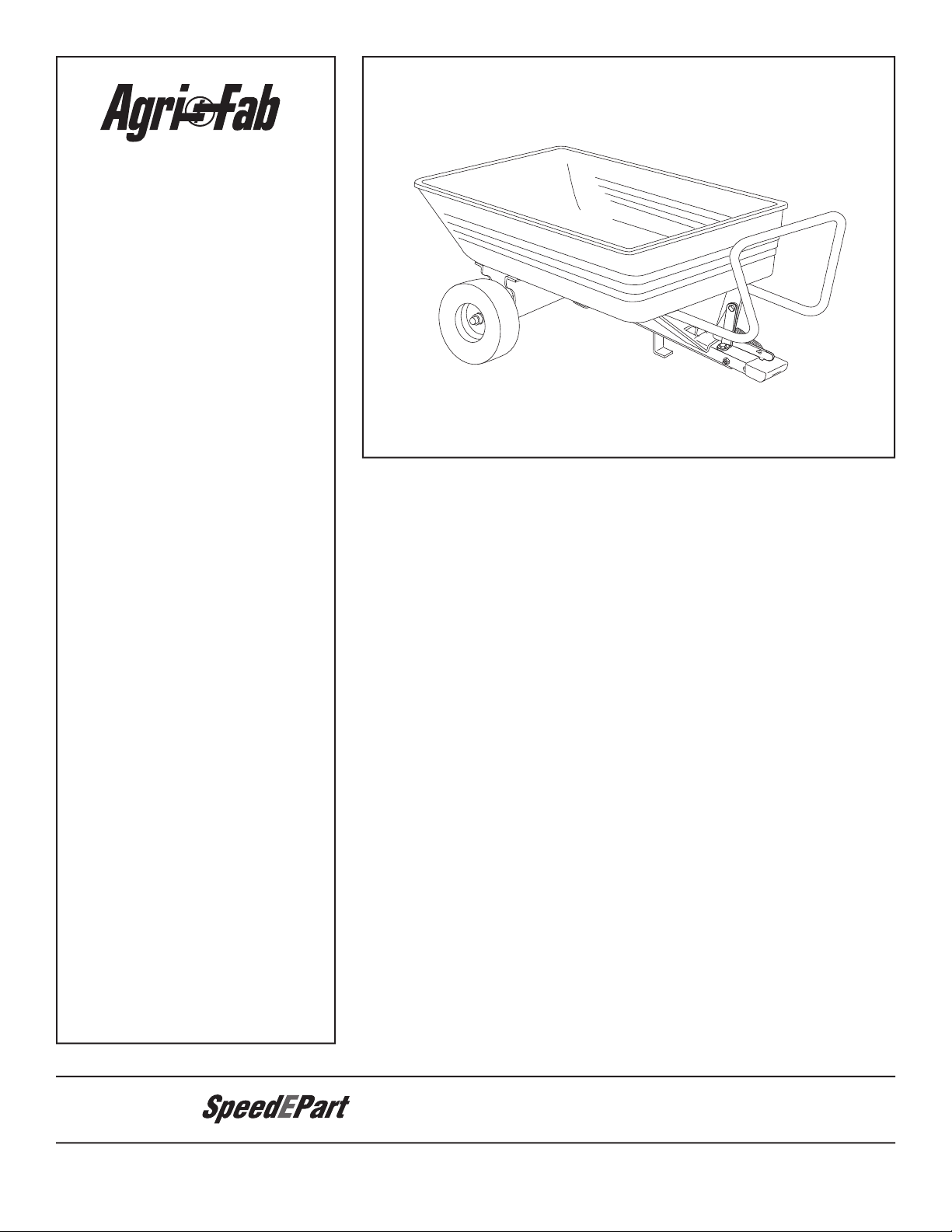
ATTENTION:
™
the fastest way to purchase parts
www.speedepart.com
Page 2
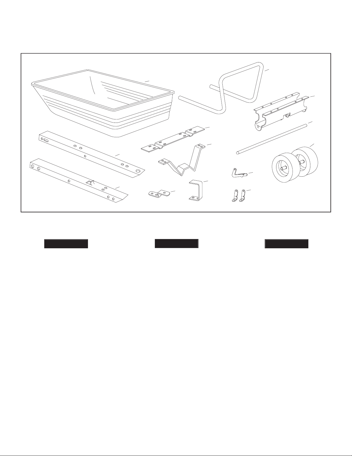
(Partes Sueltas en la Caja)
(Pièces en Vrac Dans le Carton)
ENGLISH
verrouillage
7
13
11
1
6
12
9
10
5
8
3
4
2
ESPAÑOL
FRANÇAIS
Page 3
J
K
L
M
P
Not Shown Full Size
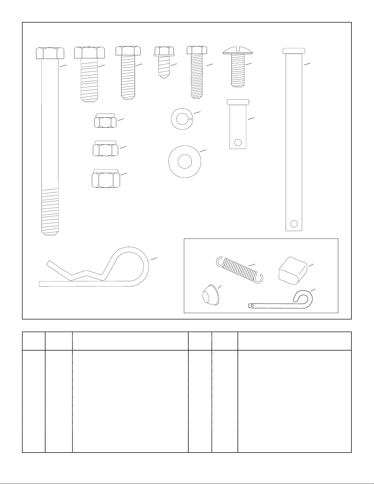
HARDWARE SHOWN FULL SIZE
GF
C
BA
I
Q
N
O
H
D
E
R
No.
J 14 Flat Washer, 1/4"
K 11 Hex Lock Nut, 1/4"
L 10 Hex Lock Nut, 5/16"
M 3 Hex Lock Nut, 3/8"
N 3 Hairpin Cotter, 1/8"
O 1 Extension Spring
P 1 Plastic Cap
Q 2 Hub Cap
R 1 Hitch Pin
No.
A 1 Hex Bolt, 3/8" x 4"
2 Hex Bolt, 3/8" x 1"
C 2 Hex Bolt, 5/16" x 1"
D 2 Screw, 1/4" x 1/2"
E 11 Hex Bolt, 1/4" x 1"
F 8 Truss Head Bolt, 5/16" x 3/4" Lg.
G 1 Clevis Pin, 3/8" x 4"
H 1 Clevis Pin, 3/8" x 1"
I 2 Lock Washer, 1/4"
Page 4

the equipment. Exercise caution at all times when using power equipment.
without checking the capability of the towing vehicle to safely pull and stop with the cart attached.
ENGLISH
Page 5
TOOLS REQUIRED FOR ASSEMBLY
Tighten.
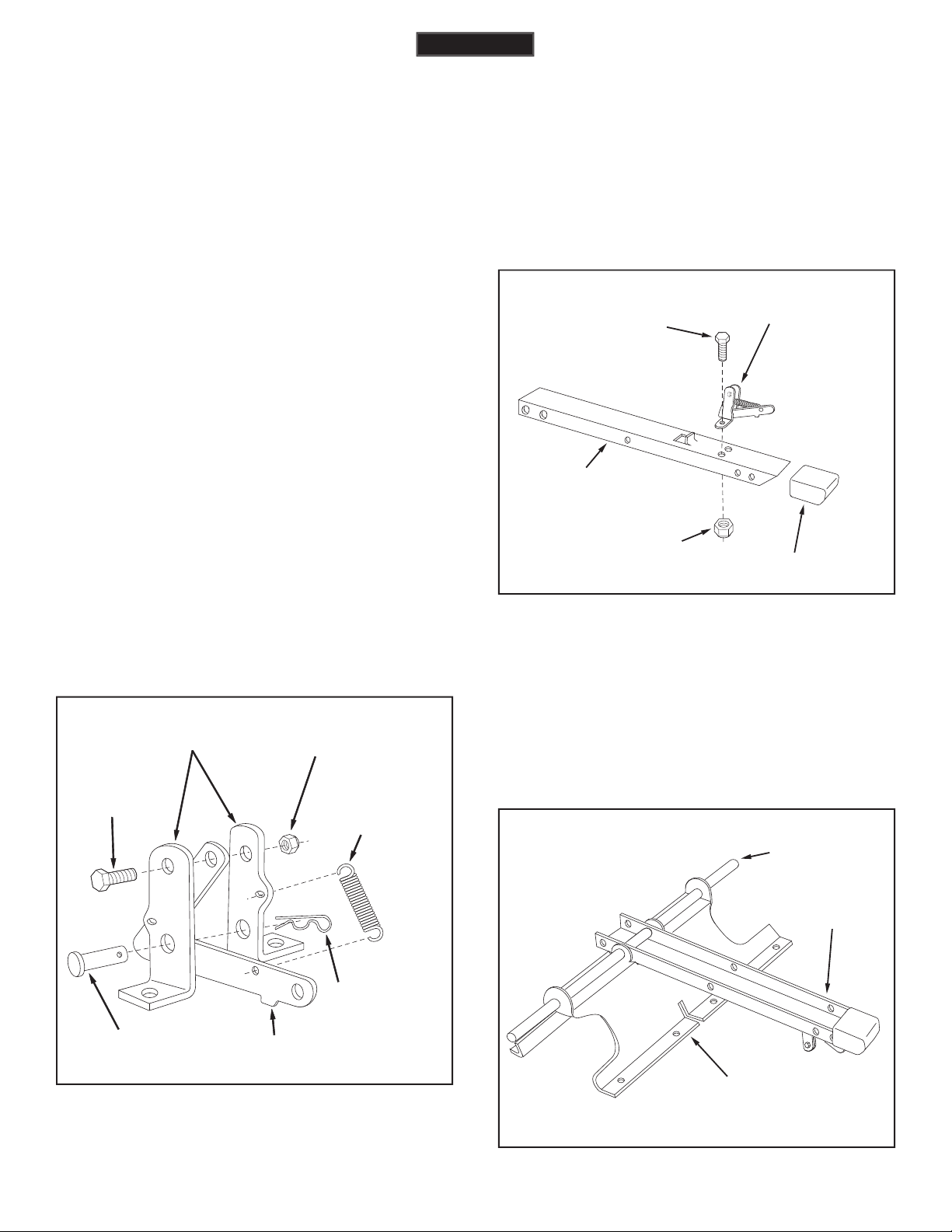
See fi gure 2.
tongue as shown in fi gure 2.
All 1/4" fl at washers should be assembled so that
they rest directly against the poly tray surface.
the extension spring (O) to the latch lock and the latch
the latch mount brackets and secure with a 1/8" hairpin
LATCH LOCK
(O) EXTENSION
SPRING
(K) 1/4" HEX
LOCK NUT
(E) 1/4" x 1"
HEX BOLT
LATCH MOUNT
BRACKETS
(N) 1/8" HAIRPIN
COTTER
(H) 3/8" x 1"
CLEVIS PIN
ENGLISH
AXLE
WHEEL
SUPPORT
REAR
TONGUE
LATCH LOCK
SUB-ASSEMBLY
(E) 1/4" x 1"
HEX BOLT
(K) 1/4" HEX
LOCK NUT
REAR
TONGUE
(P) PLASTIC CAP
Page 6
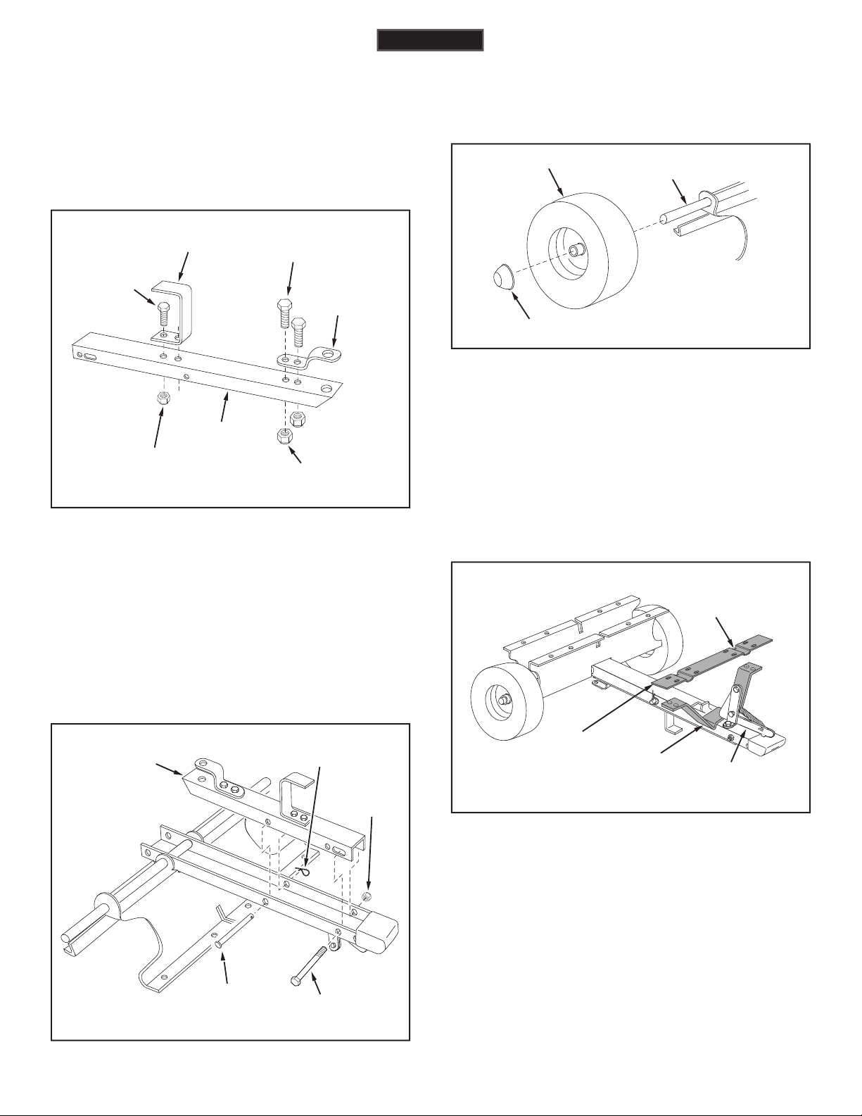
the axle. Assemble a hub cap (Q) by pressing or tapping
Tighten,
fi gure 5.
two 3/8" x 1" hex bolts (B), and 3/8" hex lock nuts (M).
Tighten.
See fi gure 4.
two 5/16" x 1" hex bolts (C) and 5/16" hex lock nuts (L).
Tighten.
See fi gure 4.
ENGLISH
(Q) HUB CAP
WHEEL
AXLE
FRONT
TONGUE
(M) 3/8" HEX
LOCK NUT
(A) 3/8" x 4"
HEX BOLT
(G) 3/8" x 4"
CLEVIS PIN
(N) 1/8" HAIRPIN
COTTER
FRONT
TONGUE
(B) 3/8" x 1"
HEX BOLT
(M) 3/8" HEX
LOCK NUT
HITCH
BRACKET
LEG STAND
BRACKET
(C) 5/16" x 1"
HEX BOLT
(L) 5/16" HEX
LOCK NUT
LATCH
STAND
BRACKET
LATCH
STAND
PLATE
TAB AT
REAR
LATCH
LOCK
See fi gure 8.
Page 7

washers (J) and 1/4" hex lock nuts (K).
yet.
See fi gure 9.
tighten
all bolts which were left loose.
the tray by depressing the detent buttons in the bottom
washer (J) onto each of the two 1/4" x 1/2" screws (D).
Assemble the screws (D) into the small holes at each
ENGLISH
HITCH
BRACKET
(N) 1/8" HAIRPIN
COTTER
(R) HITCH PIN
(E) 1/4" x 1"
HEX BOLT
(J) 1/4" FLAT
WASHER
(K) 1/4" HEX
LOCK NUT
LATCH
STAND
PLATE
(J) 1/4" FLAT
WASHER
(L) 5/16" HEX
LOCK NUT
(F) 5/16" x 3/4"
TRUSS HEAD
BOLT
(E) 1/4" x 1"
HEX BOLT
(J) 1/4" FLAT
WASHER
(K) 1/4" HEX
FRONT
TONGUE
(G) 3/8" x 4"
CLEVIS PIN
(H) 3/8" x 1"
CLEVIS PIN
LATCH LOCK
(J) 1/4" FLAT WASHER
(I) 1/4" LOCK WASHER
(D) 1/4" x 1/2" SCREW
DETENT BUTTON
HANDLE
BOTTOM OF CART
Page 8

Leave the latch lock clevis pin in place at all
times while using the cart as a push cart. The clevis pin
the front tongue into the storage position underneath
the rear tongue and secure it using the 4" long clevis pin
the plastic cap over the exposed end of the tongue.
that the latch
TOW CART
from the tongue. Remove the 4" long clevis pin and
tongue outward and secure it in the towing position using
the same clevis pin and hairpin cotter. Push the handle
the detent buttons in the bottom of the handle. Refer to
fi gure 11 on page 7.
to determine whether slope angle is too steep for safe
towing and braking capabilities whenever hauling a
THE ADDITION OF AN ACCESSORY
the load evenly in the cart.
toward the cart tongue until the latch snaps into place.
ENGLISH
Page 9

to the instructions in your vehicle owners manual.
CAUTION: DO NOT OPERATE YOUR TRACTOR AND CART ON A SLOPE
IN EXCESS OF 10 DEGREES. BE SURE OF YOUR TRACTOR'S TOWING
AND BRAKING CAPABILITIES BEFORE OPERATING ON A SLOPE.
AVOID ANY SUDDEN TURNS OR MANEUVERS WHILE ON A SLOPE.
A POWER POLE
A CORNER OF A BUILDING
OR A FENCE POST
FOLD ALONG DOTTED LINE, REPRESENTING A 10 DEGREE SLOPE
SIGHT AND HOLD THIS LEVEL WITH A VERTICAL TREE
Page 10

ESPAÑOL
Tenga cuidado con este cambio de condiciones
Page 11

ESPAÑOL
las fi guras del armado se encuentran en las páginas de
Todas las arandelas planas de 1/4” (J) deben colocarse de
vaciado completamente el cartón antes de desecharlo.
Apriete las tuercas.
Vea la Figura
Apriete todas las tuercas.
Ve la Figura 4.
Apriete todas las tuercas.
Vea la Figura
trasero de remolque, como se muestra en la Figura 5. Conecte
Apriete la conexión
forma la instalación de la otra rueda en el otro extremo del
x 1” (E), arandelas planas de 1/4" (J) y tuercas hexagonales
Vea la Figure 8.
Vea la
fondo de la manija, presione la manija, deslizándola, hasta
Page 12

tubular de manejo y vuelque la carretilla hacia adelante.
Asegúrese de que el mecanismo de la aldaba en el elemento de
tapa plástica del elemento de remolque. Remueva el pasador de
frontal de remolque en su posición de almacenamiento, debajo
frente de la caja. Consulte la Figura 11.
y la zona del eje en la que gira la lengüeta de enganche.
forma periódica. Utilice aceite de automoción para cojinetes
ESPAÑOL
Tenga en cuanta las condiciones cambiantes
Page 13

PRECAUCION: NO OPERE EL TRACTOR REMOLCANDO EL CARRO EN
UNA PENDIENTE DE MAS DE 10°. VERIFIQUE LA CAPACIDAD DE SU
TRACTOR PARA REMOLCAR Y FRENAR ADECUADAMENTE ANTES DE
OPERAR EN UNA PENDIENTE. EVITE GIROS O MANIOBRAS BRUSCAS
CUANDO OPERA EN UNA PENDIENTE.
ESPAÑOL
UN POSTE DE CORRIENTE ELECTRICA O TELEFONO
UNA ESQUINA DE UN EDIFICIO
O UN POSTE DE UNA CERCA
DOBLE LA HOJA A LO LARGO DE LA LINEA PUNTEADA,
LA CUAL REPRESENTA UNA PENDIENTE DE 10 GRADOS
ALINEE LA LINEA VERTICAL DEL EXTREMO IZQUIERDO
DEL GRAFICO CON UN OBJETO VERTICAL EN EL CAMPO, POR EJEMPLO
Page 14

Tout appareil mécanique utilisé incorrectement peut être la cause de blessures. L’utilisateur doit bien en maîtriser le fonctionnement.
La stabilité et la capacité de
freinage d’un véhicule peut être diminuée
FRANÇAIS
Page 15

FRANÇAIS
La droite et la gauche sont déterminées par rapport à
Les fi gures à propos du montage se trouvent sur les
Toutes les rondelles plates de 1/4 po. (J) doivent
Resserrer.
Voir fi gure 2.
faisant passer dans le support de roues puis par la barre
Voir fi gure 4.
Voir fi gure 4.
fi gure 5.
tel qu’illustré à la fi gure 5, et fi xer avec une goupille d’attelage
Tournez la plaque de support du mécanisme de verrouillage
verrouillage et sur le support du mécanisme de verrouillage
Reportez-vous à la
fi gure 8.
trous intérieurs de la plaque de support du mécanisme de
verrouillage. Fixez les boulons en utilisant quatre rondelles
Reportez-vous à la fi gure 9.
vous à la fi gure 10.
Page 16

FRANÇAIS
ATTENTION:
Afi n d’éviter tout risque de
La stabilité et la capacité de
freinage d’un véhicule peut être diminuée
terminée, pousser le plateau contre la barre d’attelage jusqu’à
Page 17

FRANÇAIS
ATTENTION: NE PAS UTILISER LE TRACTEUR ET LA REMORQUE SUR
UNE PENTE INCLINÉE À PLUS DE 10 DEGRÉS. VÉRIFIEZ LA TRACTION
ET LE FREINAGE DE VOTRE TRACTEUR AVANT DE CONDUIRE SUR
UNE PENTE. ÉVITEZ TOUTE MANOEUVRE BRUSQUE LORSQUE VOUS
CONDUISEZ SUR UNE PENTE.
UN POTEAU ÉLECTRIQUE
LE COIN DE TOUT ÉDIFICE
UN PIQUET DE CLÔTURE
PLIEZ SELON LES POINTILL
ÉS, REPR
ÉSENTANT UNE PENTE DE 10 DEGR
ÉS
PLACEZ CETTE FEUILLE À NIVEAU CONTRE UN ARBRE DROIT
Page 18

24
18
18
1
21
22
9
23
23
3
2
5
30
15
20
13
19
14
29
26
26
10
25
11
22
24
16
2
17
17
28
27
8
4
12
26
6
7
22
31
32
24
18
18
Page 19

REF. PART QTY. DESCRIPTION
NO. NO.
1 48791 1 Poly Tray
2 24908 1 Axle
3 48497 2 Wheel Assembly
4 24392 1 Tongue, Front
5 24391 1 Tongue, Rear
6 25274 1 Latch Stand Plate
7 23297 1 Latch Stand Bracket
8 48955 1 Handle Tube
9 25064 1 Wheel Support
10 62020 1 Latch Lock
11 23470 2 Bracket, Latch Mounting
12 23353 1 Hitch Pin
13 23014 1 Hitch Bracket
14 24390 1 Leg Stand Bracket
15 47029 1 Clevis Pin, 3/8" x 4"
16 45091 1 Clevis Pin 3/8" x 1"
17 HA21362 3 Hex Lock Nut (Nylock), 3/8-16 Thread *
18 43088 14 Washer, Flat 1/4" Std. Wrought
19 43001 2 Hex Bolt, 3/8-16 x 1" Lg. *
20 43177 2 Lock Washer, 1/4" *
21 43814 8 Slotted Truss Head Bolt, 5/16-18 x 3/4" Lg.*
22 46978 11 Hex Nut (Nylock), 1/4-20
23 47810 10 Hex Nut (Nylock), 5/16-18
24 43661 11 Hex Bolt, 1/4-20 x 1" *
25 43000 1 Extension Spring
26 43343 3 Hairpin, Cotter 1/8"
27 48499 2 Hub Cap
28 47038 1 Plastic Cap
29 43063 2 Hex Bolt, 5/16-18 x 1" Lg. *
30 43036 1 Hex Bolt, 3/8-16 x 4" Lg. *
31 49166 2 Detent Button
32 48840 2 Screw, 1/4"-20 x 1/2" Thread *
49167 1 Owner's Manual
the fastest way to purchase parts
www.speedepart.com
Page 20

Agri-Fab, Inc.
www.agri-fab.com
the fastest way to purchase parts
www.speedepart.com
© 2004 Agri-Fab, Inc.
 Loading...