

Page 1

!
ER
O
S
M
ITH
2
O
CK
S
™
m
OWNERS MANUAL
MANUAL DEL USUARIO
NOTICE D’UTILISATION
Model No.
Modelo No.
Modèle No.
45-0331
S
CK
2
ITH
M
S
O
ER
CAUTION:
Read Rules for
Safe Operation
and Instructions
Carefully
PRECAUCION:
Lea cuidadosamente
los Procedimientos e
Instrucciones para la
Operación Segura de la
Máquina.
ATTENTION:
Lire et suivre attentivement
les instructions et
consignes de sécurité de
cette notice.
38" LAWNSWEEPER
BARREDORA DE CESPED DE 96 cm
BALAYEUSE DE 96 cm
• Safety
• Assembly
• Operation
• Maintenance
• Parts
• Seguridad
• Montaje
• Operación
• Mantenimiento
• Piezas de Repuesto
• Sécurité
• Assemblage
• Fonctionnement
• Maintenance
• Pièces de Rechange
the fastest way to purchase parts
PRINTED IN U.S.A. FORM NO. 49131 (REV. 4/05)
www.speedepart.co
Page 2
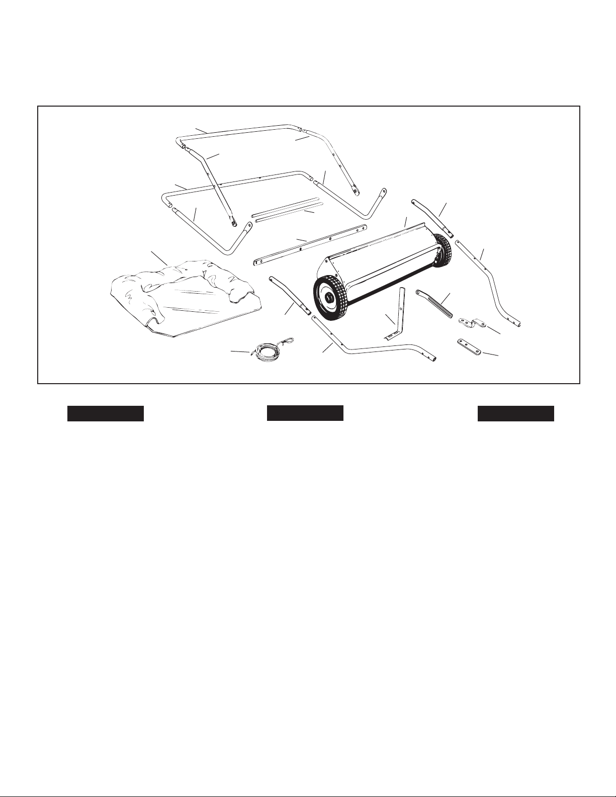
CARTON CONTENTS (Loose Parts in Carton)
CONTENIDO DE LA CAJA (Partes Sueltas en la Caja)
CONTENU DU CARTON (Pièces en Vrac Dans le Carton)
12
12
10
ENGLISH
1. Sweeper Housing Assembly
2. Bag Arm Tube (2)
3. Hitch Tube, L.H.
4. Hitch Bracket
5. Hitch Bracket (Straight)
6. Height Adjustment Strap
7. Height Adjustment Handle
8. Hitch Tube, R.H.
9. Rope
10. Hopper Bag
11. Upper Hopper Side Tube (2)
12. Rear Hopper Tube (2)
13. Lower Hopper Side Tube (2)
14. Hopper Support Rod (2)
15. Bag Frame Strap
11
13
9
11
13
14
15
2
8
ESPAÑOL
1. Conjunto de Carcaza de la Barredora
2. Brazo del Tubo de la Bolsa (2)
3. Tubo de Enganche (Mano Izquierda)
4. Ménsula de Enganche
5. Ménsula de Enganche (Recta)
6. Banda de Ajuste de Altura
7. Manija de Ajuste de Altura
8. Tubo de Enganche (Mano Derecha)
9. Cuerda
10. Bolsa de la Tolva
11. Tubo Lateral de la Parte Superior de
la Tolva (2)
12. Tubo de la Parte Posterior de la Tolva (2)
13. Tubo Lateral de la Parte Inferior de
la Tolva (2)
14. Barra de Soporte de la Tolva (2)
15. Banda del Marco de la Bolsa
2
1
3
6
7
4
5
FRANÇAIS
1. Bâti de la balayeuse
2. Tube du bras du sac (2)
3. Tube d‘attelage, côté droit
4. Support de l’attelage
5. Support de l’attelage, droit
6. Étrier de réglage de la hauteur
7. Poignée de réglage de la hauteur
8. Tube d’attelage, côté droit.
9. Cordage
10. Sac de récupération des débris
11. Tube latéral supérieur de la
trémie (2)
12. Tube arrière de la trémie (2)
13. Tube latéral inférieur de la
trémie (2)
14. Tiges de support de la trémie (2)
15. Bride du cadre du sac
2
Page 3
ENGLISH
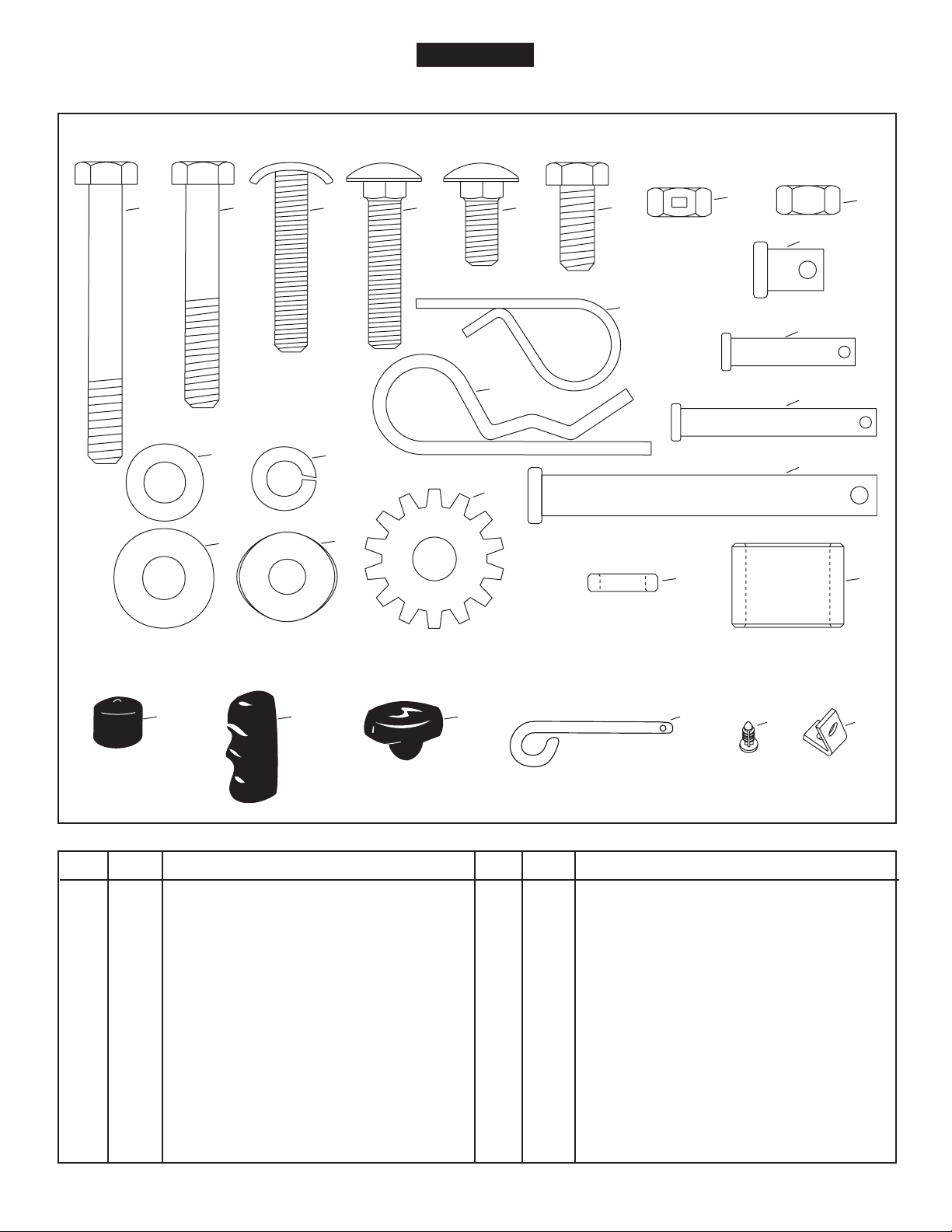
SHOWN FULL SIZE
A B C
I
J
K
L
D
E
N
M
F
O
T U
G
P
Q
R
S
H
NOT SHOWN FULL SIZE
V W X
REF. QTY. DESCRIPTION
A 2 Hex Bolt, 5/16 x 2-1/2" Lg.
B 2 Hex Bolt, 5/16 x 2" Lg.
C 2 Curved Head Bolt, 5/16" x 1-5/8"
D 4 Carriage Bolt, 5/16" x 1-1/2"
E 1 Carriage Bolt, 5/16 x 3/4" Lg.
F 2 Hex Bolt, 5/16" x 3/4"
G 6 Hex Lock Nut, 5/16"
H 6 Hex Nut (Plain), 5/16"
I 2 Flat Washer, 5/16" (Small)
J 2 Flat Washer, 5/16" Std. Wrt.
K 8 Lock Washer, 5/16"
L 2 Bowed Washer
M 1 Lock Washer (Tooth), 5/16"
Y
REF. QTY. DESCRIPTION
N 1 Hair Cotter Pin, 1/8"
O 8 Hair Cotter Pin, 3/32"
P 2 Clevis Pin, 3/8" x 1/2"
Q 2 Clevis Pin, 1/4" x 1-1/8"
R 2 Clevis Pin, 1/4" x 1-3/4"
S 2 Clevis Pin, 3/8" x 3"
T 1 Spacer Bushing,
U 2 Hitch Spacer, 3/4"
V 2 Vinyl Cap
W 1 Grip
X 1 Knob, Plastic
Y 1 Hitch Pin
Z 4 Plastic Plug
AA 1 Angle Bracket
Z
AA
3
Page 4

ENGLISH
SAFETY RULES
Remember, any power equipment can cause injury if operated improperly or if the user does not understand how to operate
the equipment. Exercise caution at all times when using power equipment.
1. Read the vehicle and sweeper owners manuals and
know how to operate your vehicle and sweeper before
using this sweeper attachment. Always instruct other
users before they operate the sweeper.
2. Do not permit children to operate sweeper.
3. Do not permit anyone to ride on sweeper.
4. Never attach the hopper rope to any part of your body
or clothing! Never hold onto the rope while towing the
sweeper! Attach the rope to the towing vehicle to keep
it away from wheels and rotating parts.
5. Operate the sweeper at reduced speed on rough terrain, near ditches and on hillsides to prevent loss of
control.
6. Vehicle braking and stability may be affected with
the attachment of this sweeper. Do not fi ll sweeper to
maximum capacity without checking the capability of the
towing vehicle to safely pull and stop with the sweeper
attached. Stay off of steep slopes.
7. Stop and inspect vehicle and sweeper for damage after
striking an object. Repair any damage before continuing
operation.
8. Keep sweeper away from fi re. Excessive heat can damage the brushes and hopper bag and could cause the
bag and its contents to burn.
9. Before storing the sweeper, always empty the hopper
bag to avoid spontaneous combustion.
10. Follow maintenance and lubrication instructions as
outlined in the maintenance section of this manual.
Look for this symbol to point out important safety precautions. It means--Attention!!
Become alert!! Your safety is involved.
4
Page 5
ENGLISH
CONTENTS
SAFETY ...........................................................................4
ASSEMBLY ......................................................................5
OPERATION .................................................................. 11
MAINTENANCE ............................................................11
STORAGE ..................................................................... 11
SERVICE AND ADJUSTMENTS ...................................12
TROUBLESHOOTING ...................................................12
REPAIR PARTS .............................................................22
ASSEMBLY
TOOLS REQUIRED FOR ASSEMBLY
(1) Knife or Scissors
(2) 1/2" Open End or Box End Wrenches
All loose parts are shown on page 2. Fasteners in the parts
bag are shown full size on page 3.
Remove the hardware pack and all loose parts from the
carton and verify that all the parts and fasteners shown on
pages 2 and 3 are included.
2. Cut off the plastic tie that holds the height adjustment
tube in place.
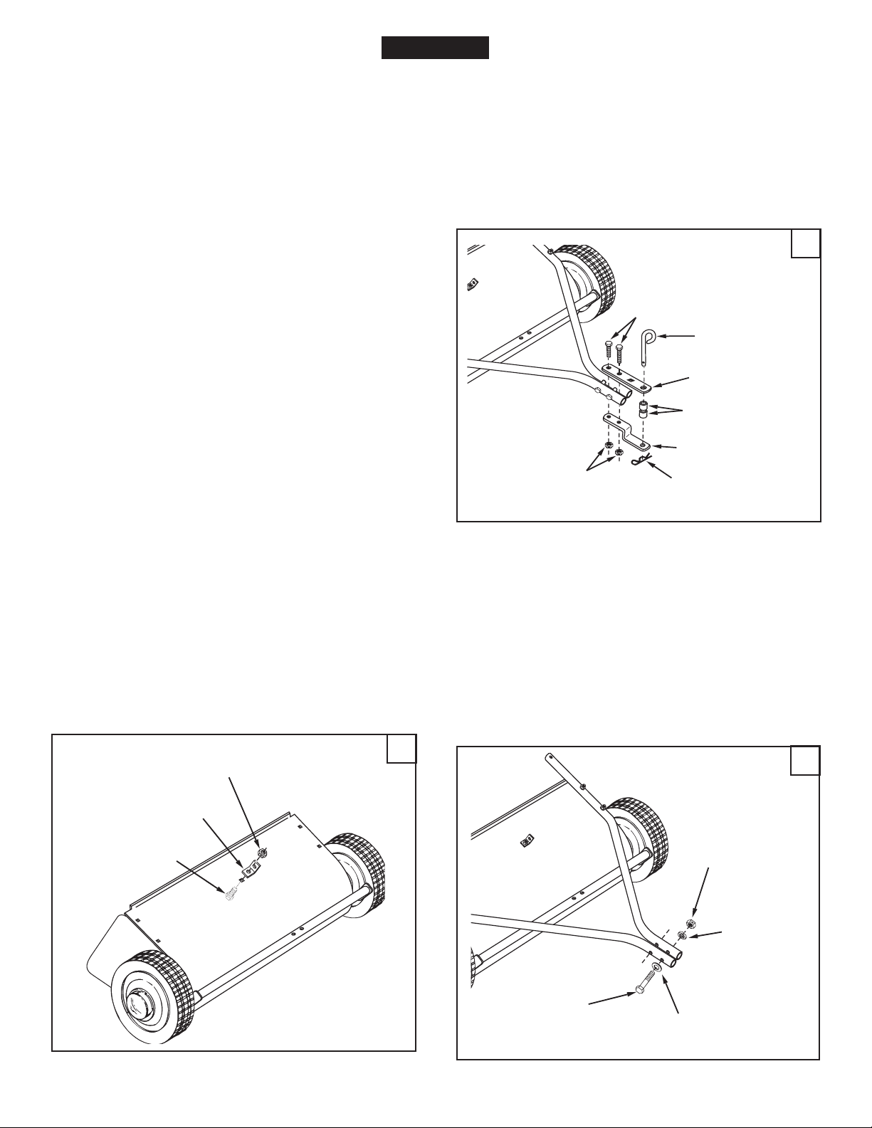
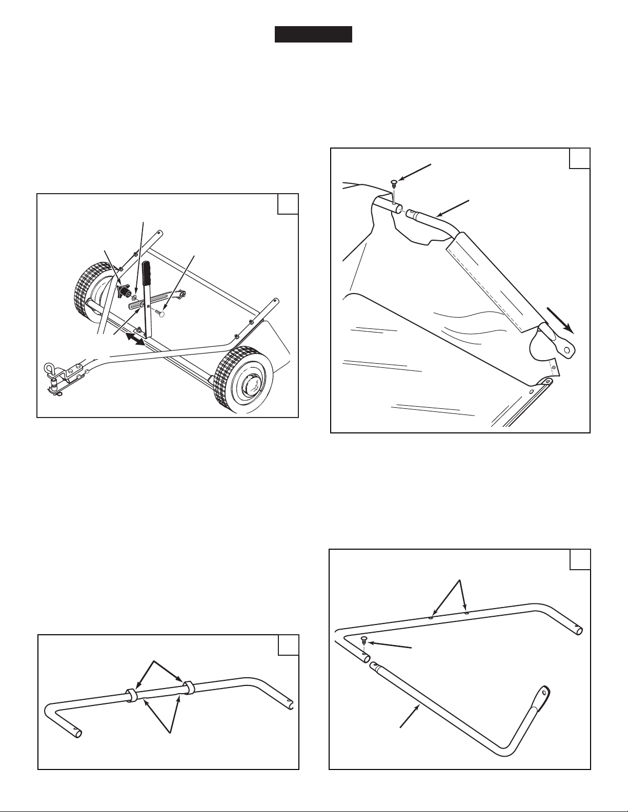
3. (Figure 2) Assemble the R.H. hitch tube to the sweeper
housing using two 5/16" x 1-1/2" carriage bolts (D),
5/16" lock washers (K) and 5/16" hex nuts (H). Do not
tighten yet. Repeat for the L.H. hitch tube.
2
5/16" x 2"
HEX BOLT (B)
HITCH PIN (Y)
HITCH BRACKET
(STRAIGHT)
3/4" SPACER (U)
HITCH BRACKET
5/16" HEX
LOCK NUT (G)
1/8" HAIR
COTTER PIN (N)
ASSEMBLY OF SWEEPER
Note: Right hand (R.H.) and left hand (L.H.) are determined
from the operator's position while seated on the tractor.
1. (Figure 1) Assemble the angle bracket to the sweeper
housing using a 5/16" x 3/4" hex bolt (F) and a 5/16"
hex lock nut (G). Make sure the bracket is turned as
shown and aligned straight with the housing and then
tighten.
5/16" HEX
LOCKNUT (G)
ANGLE
BRACKET
5/16" x 3/4"
HEX BOLT (F)
1
4. (Figure 3) Fasten the hitch tubes together using two
5/16" x 2-1/2" hex bolts (A), 5/16" small fl at washers
(I), 5/16" lock washers (K) and 5/16" hex lock nuts (G).
Do not tighten yet.
3
5/16" HEX
LOCK NUT (G)
5/16" LOCK
WASHER (K)
5/16" x 2-1/2"
HEX BOLT (A)
5
5/16" SMALL FLAT
WASHER (I)
Page 6
ENGLISH
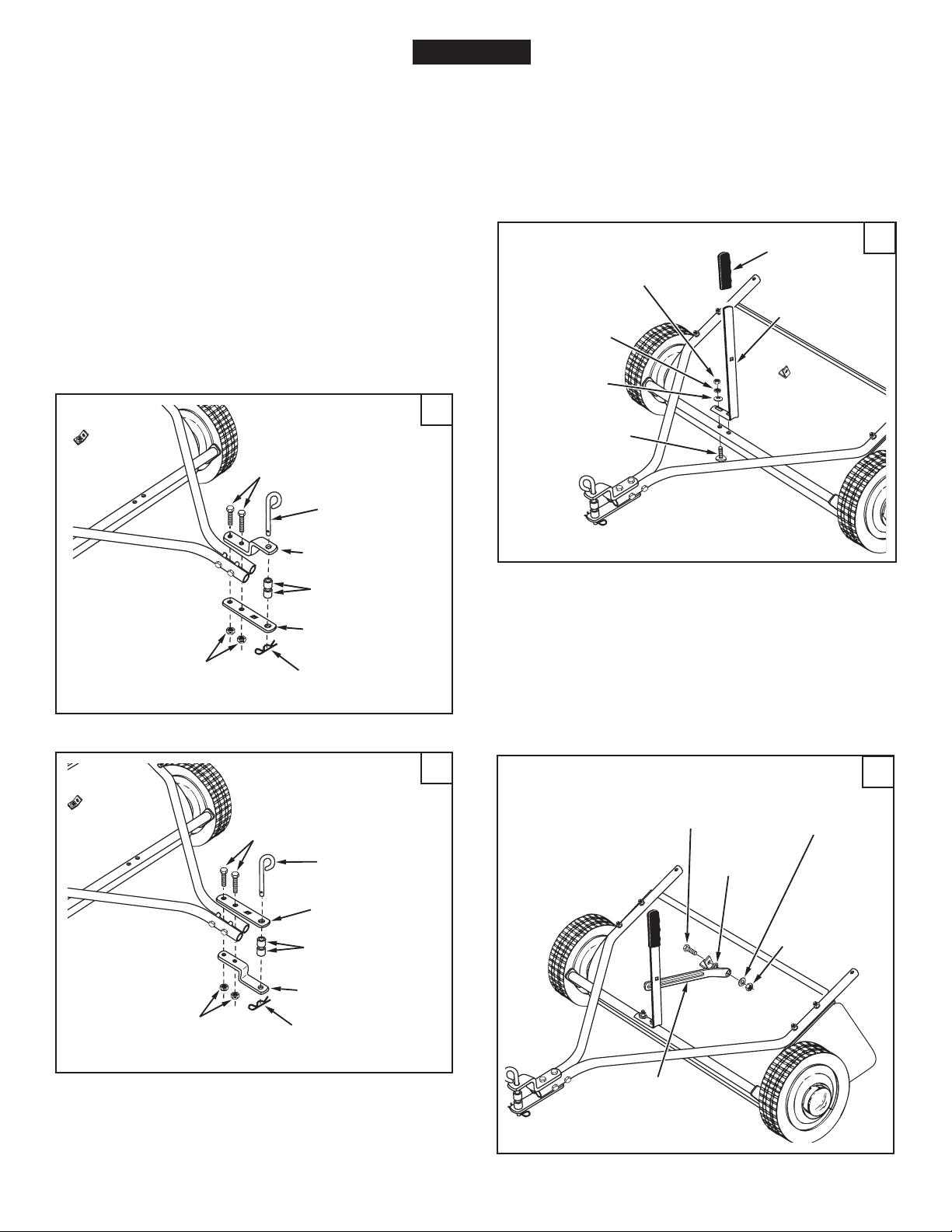
If your tractor hitch has 11" to 13" ground clearance refer to fi gure 4. If your tractor hitch has 8" to 11" ground
clearance refer to fi gure 5.
5. (Figure 4 or 5) Assemble the hitch brackets to the hitch
tubes using two 5/16" x 2" hex bolts (B) and 5/16" hex
lock nuts (G). The bolts should straddle the front hitch
tube bolt. Do not tighten yet.
6. At this time tighten the four bolts fastening the hitch
tubes to the sweeper housing. Next, tighten the two bolts
fastening the ends of the hitch tubes together. Finally,
tighten the two bolts fastening the hitch brackets to the
hitch tubes.
7. (Figure 4 or 5) Assemble the hitch pin (Y), two 3/4"
spacers (U) and the 1/8" hair cotter pin (N) to the hitch
brackets.
8. (Figure 6) Assemble the height adjustment handle to
the height adjustment tube as shown in fi gure six. Use
two curved head bolts (C), bowed washers (L), 5/16"
lock washers (K) and 5/16" hex nuts (H). Do not tighten
yet.
9. (Figure 6) Assemble the grip onto the height adjustment
handle.
6
5/16" HEX NUT (H)
5/16" LOCK
WASHER (K)
BOWED
WASHER (L)
GRIP
HEIGHT
ADJUSTMENT
HANDLE
5/16" HEX
LOCK NUT (G)
5/16" x 2"
HEX BOLT (B)
HITCH PIN (Y)
HITCH BRACKET
3/4" SPACER (U)
HITCH BRACKET
(STRAIGHT)
1/8" HAIR
COTTER PIN (N)
5/16" x 2"
HEX BOLT (B)
HITCH PIN (Y)
4
CURVED
HEAD BOLT (C)
10. (Figure 7) Insert a 5/16" x 3/4" hex bolt (F) through the
angle bracket. Assemble onto the bolt (in order) the
spacer bushing (T), the height adjustment strap, a 5/16"
fl at washer (J) and a 5/16" hex lock nut (G). Tighten.
5
5/16" x 3/4"
HEX BOLT (F)
SPACER
BUSHING (T)
5/16" FLAT
WASHER (J)
7
5/16" HEX
LOCK NUT (G)
HITCH BRACKET
(STRAIGHT)
3/4" SPACER (U)
HITCH BRACKET
1/8" HAIR
COTTER PIN (N)
5/16" HEX
LOCK NUT (G)
HEIGHT
ADJUSTMENT
STRAP
6
Page 7
ENGLISH
11. (Figure 8) Position the height adjustment handle side to
side so that the tooth lock washer (M) can fi t between
the handle and the height adjustment strap. Tighten
the nuts securing the height adjustment handle.
12. (Figure 8) Insert the 5/16" x 3/4" carriage bolt (E)
through the height adjustment handle. Assemble onto
the bolt, in order, the 5/16" tooth-lock washer (M), the
height adjustment strap, a 5/16" fl at washer (J) and the
plastic knob.
8
PLASTIC
KNOB
TOOTH LOCK
WASHER (M)
5/16" FLAT
WASHER (J)
5/16" x 3/4"
CARRIAGE BOLT (E)
2. (Figure 10) Insert the two upper hopper side tubes
through the stitched fl aps on each side of the hopper
bag.
3. (Figure 10) Assemble the ends of the rear hopper tube
onto the ends of the upper hopper side tubes. Fasten
together using plastic plugs (Z).
PLASTIC PLUG (Z)
UPPER HOPPER
SIDE TUBE
10
ASSEMBLY OF HOPPER BAG
1. (Figure 9) Turn a rear hopper tube so that the brace
holes in the middle of the tube face down. Slide the
tube through the two loops sewn to the top rear seam
inside the hopper bag.
INNER BAG LOOPS
REAR HOPPER TUBE
(brace holes on bottom)
9
4. (Figure 11) Turn the second rear hopper tube so that
the brace holes in the middle of the tube face up. Assemble the ends of the rear hopper tube onto the ends
of the lower hopper side tubes. Fasten together using
plastic plugs (Z).
REAR HOPPER TUBE
(brace holes on top)
PLASTIC PLUG (Z)
LOWER
HOPPER
SIDE TUBE
7
11
Page 8
ENGLISH
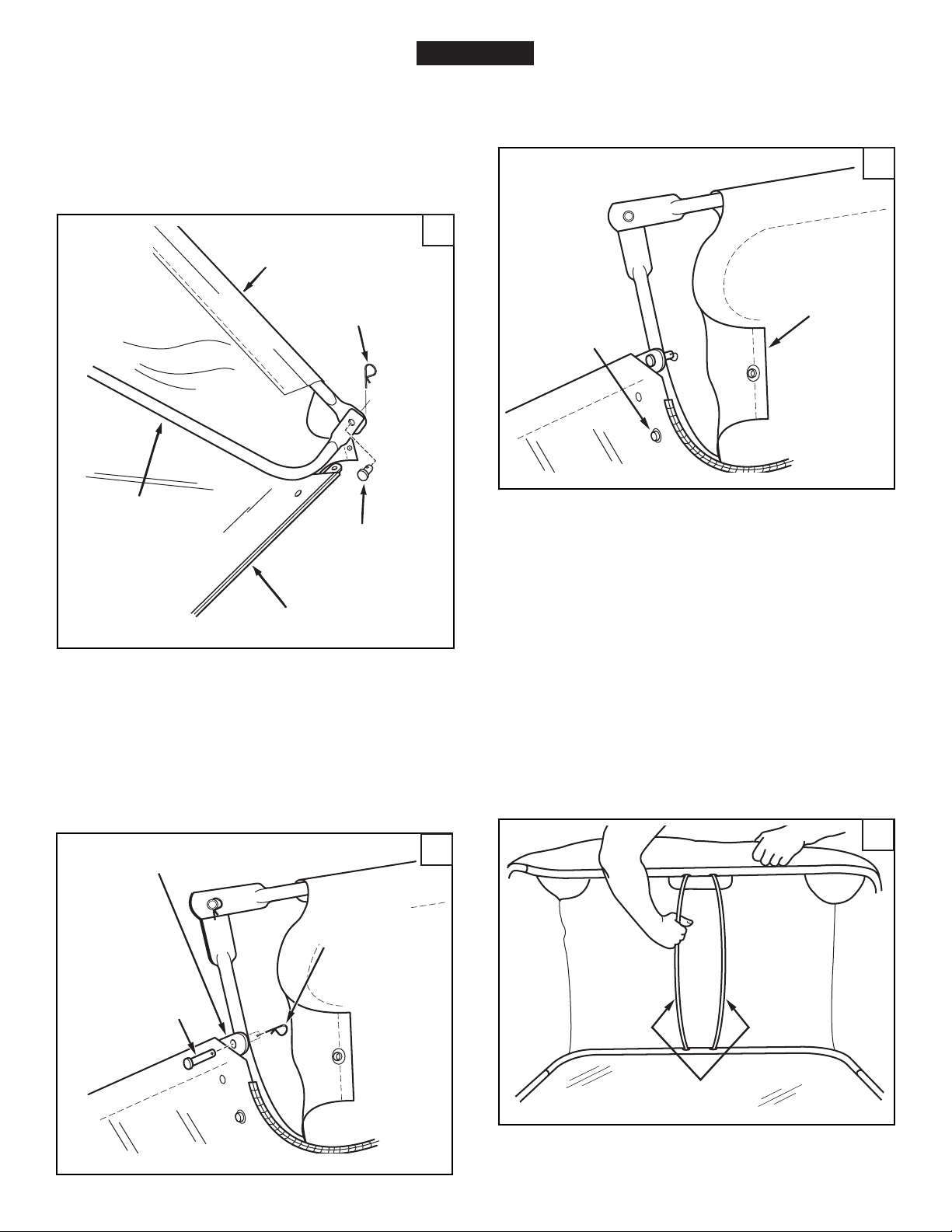
5. (Figure 12) Place the assembled lower hopper tubes
into the bottom of the hopper bag.
6. (Figure 12) Attach the ends of the lower hopper side
tubes to the inside of the upper hopper side tubes using
two 3/8" x 1/2" clevis pins (P) inserted from the inside,
and two 3/32" hair cotter pins (O).
9. (Figure 14) Secure the bag corners around the lower
hopper side tubes by snapping the bag fl aps to the bag
bottom on both sides.
14
LOWER HOPPER
SIDE TUBE
UPPER HOPPER
SIDE TUBE
3/32" HAIR
COTTER PIN (O)
3/8" x 1/2"
CLEVIS PIN (P)
HOPPER BAG
BOTTOM
12
FLAP
SNAP
FIGURE 14
IMPORTANT: Do not over bend the support rods during
the following step. Over bending will cause the steel rods
to loose supporting tension.
7. (Figure 13) Insert the bag frame strap into the stitched
sleeve along the front edge of the bag bottom.
8. (Figure 13) Assemble the bag frame strap to the lower
hopper side tubes using two 1/4" x 1-1/8" clevis pins
(Q) and 3/32" hair cotter pins (O).
BAG FRAME STRAP
3/32" HAIR
COTTER PIN (O)
1/4" x 1-1/8"
CLEVIS PIN (Q)
13
10. (Figure 15) Tip the hopper onto it's back to assemble
the two hopper support rods. Place the ends of each
rod into the upper and lower rear hopper tubes, bending
the rod just enough to fi t into the holes in the tubes.
15
SUPPORT
RODS
8
Page 9

ENGLISH
11. (Figure 16) Feel along the stitched fl ap on the hopper
bag to locate the lower hole in each upper hopper side
tube. Pierce a hole through both sides of the stitched
fl aps in alignment with the lower hole.
UPPER HOLE
16
LOWER HOLE
UPPER HOPPER SIDE TUBE
14. (Figure 18) Secure the rope to the top center of the
hopper bag frame.
18
15. (Figure 19) To assemble the hopper bag to the sweeper,
slide the ends of the bag arm tubes into the ends of the
sweeper's hitch tubes and secure with two 1/4" x 1-3/4"
clevis pins (R) and 3/32" hair cotter pins (O).
12. (Figure 17) Insert a 3/8" x 3" clevis pin (S) through
the lower hole in each upper hopper side tube. Next,
assemble a bag arm tube (pointing in direction shown)
onto each clevis pin and secure it with a 3/32" hair cotter
pin (O).
13. (Figure 17) Assemble a vinyl cap (V) onto the end of
each bag arm tube.
17
VINYL CAP
LOWER HOLE
3/32" HAIR
COTTER PIN (O)
3/8" x 3"
CLEVIS PIN (S)
BAG ARM TUBE
BAG ARM TUBE
3/32" HAIR
COTTER PIN (O)
19
1/4" x 1-3/4"
CLEVIS PIN (R)
9
Page 10

ENGLISH
!
ER
OSMITH
2
O
CKS
ATTACHING SWEEPER HITCH TO TRACTOR
(Figures 20, 21, 22)
1. Place the tractor and sweeper on a fl at level surface.
2. Set the sweeper height adjustment handle to about the
middle of its adjustment range.
3. Attach the sweeper hitch brackets to the tractor hitch,
arranging the 3/4" spacers to make the bottom of the
sweeper bag as level with the ground as possible. See
fi gure 21 for tractor hitches that are 11" to 13" above
the ground. See fi gure 22 for tractor hitches that are 8"
to 11" above the ground.
IMPORTANT: For best performance, the bottom of the
sweeper bag should be as level with the ground as possible
with at least 5" ground clearance. See fi gure 20.
5" Min.
20
CKS
OSMITH2
ER
11"-13"
TRACTOR HITCH
2221
8"-11"
TRACTOR HITCH
Tractor hitches with 11" to 13" ground clearance.
Tractor hitches with 8" to 11" ground clearance.
10
Page 11

ENGLISH
OPERATION
HOW TO USE YOUR SWEEPER
BRUSH HEIGHT ADJUSTMENT
To adjust your sweeper brushes to the best operating
height, loosen the adjustment knob and push down on
the height adjustment lever to raise the brush. Best adjustment is when the brush setting is 1/2" down into the
grass. Always mow the grass to an even height before
sweeping.
SWEEPING SPEED
Tr y a starting speed of approximately 3 m.p.h. (third gear
on most tractors). Depending on the conditions, it may
be necessary to adjust the sweeping speed in order to
achieve best results.
DUMPING OF SWEEPER
Your sweeper can be dumped easily without getting
off of the rider or tractor. Simply pull the rope forward
to dump the hopper. Always empty hopper after each
use.
CAUTION: Never attach the hopper rope
to any part of your body or clothing! Never
hold onto the rope while towing the sweeper!
Attach the rope to the towing vehicle to keep
it away from wheels and rotating parts.
4. (Figure 23) Lubricate the brush shaft bearing twice a
year with a few drops of light weight oil.
HEIGHT ADJUSTMENT SLOT
OIL BEARINGS HERE
FLAT WASHER
HEX BOLT
5. Lubricate the wheel bearings each season. Remove
the hub cap and apply a few drops of light weight oil.
6. (Figure 24) Every two years, remove the wheels and
clean the gears found inside the wheel housing. After
cleaning, lubricate the gears with an even coat of light
grease. To remove the wheel, pop off the hub cap and
remove the lock nut and fl at washer.
HEX BOLT FLAT WASHER
23
24
CAUTION: Keep sweeper away from fi re.
Excessive heat can damage the brushes and
hopper bag and could cause the bag and its
contents to burn.
MAINTENANCE
CUSTOMER RESPONSIBILITIES
1. Check for loose fasteners before each use.
2. Clean the sweeper after each use.
a. Clean sweeper housing with a soft brush or cloth.
b. Clean debris from hopper bag with a brush or
broom.
c. Remove any material which has wrapped around
brushes or ends of brush shaft.
3. Inspect for worn or damaged parts, such as brushes
and wheels before each use. Replace as necessary.
FLAT WASHER
HUB CAP
SPACER
HEX LOCK NUT
STORAGE
CAUTION: Before storing the sweeper,
always empty the hopper bag to avoid spontaneous combustion.
1. Clean the sweeper and hopper bag thoroughly to help
prevent rust and mildew.
2. To collapse the hopper bag for storage, remove the two
hopper support rods from the rear of the hopper.
3. Store in a dry area.
11
Page 12

ENGLISH
SERVICE AND ADJUSTMENTS
BRUSH REPLACEMENT
NOTE: Brush replacement should be done one brush at
a time.
1. Remove the hopper bag from the sweeper.
2. (Figure 25) Loosen the hex bolts and lock nuts on two
single brush retainers which clamp one brush to the
double brush retainers. Do Not loosen or remove the
bolts which fasten the double brush retainers to the
brush shaft.
3. (Figure 25) Slide the brush out of the retainers, noting
on which side of the brush the bristles overlap.
4. (Figure 25) Install new brush, making sure the bristles
overlap on the same side of the brush as before.
25
BRUSH ROTATION
BRUSH
SHAFT
OVERLAP
BRISTLES
WHEEL GEAR AND PAWL SERVICE
IMPORTANT: Do not remove both wheels at the same
time to avoid mixing of parts. (The R.H. and L.H. ratchet
gears are not interchangeable.) Make notes on the position
of washers and snap rings during disassembly.
1. Remove only one wheel from the sweeper.
2. Remove the retaining rings and washers which hold the
ratchet gear onto the brush shaft.
3. (Figure 26) Remove the gear by sliding it off the brush
shaft. (Look for the drive pin, which may fall out of the
brush shaft when the ratchet gear is removed.)
4. To reassemble, insert the drive pin through the hole
near the end of the brush shaft. Make sure the pin slides
back and forth easily in the shaft.
5. Lightly grease the shaft and fi ll the ratchet gear with
grease. Assemble the ratchet gear back onto the
shaft.
6. Lightly grease the axle and the gear teeth on the wheel,
and then reassemble the wheel. The brushes should
rotate only during forward rotation of the wheel. If the
brushes are driven (rotated) by both forward and reverse
rotation of the wheel, the drive pin is jamming in the
ratchet gear. Disassemble to clean and lubricate the
drive pin and the ratchet gear.
DOUBLE BRUSH RETAINER
OVERLAP
BRISTLES
BRUSH ROTATION
TROUBLESHOOTING
SINGLE
BRUSH
RETAINERS
26
RATCHET
GEAR
DRIVE
PIN
Wheels skid when sweeping. 1. Adjust height till brushes are 1/2" down into grass.
1. Brushes set too low.
2. Brushes are jammed.
3. Wheels are jammed.
2. Stop sweeper. Remove obstruction.
3. Remove one wheel at a time to check for obstruction or
damage. Refer to Service and Adjustments section.
12
Page 13

13
Page 14

ESPAÑOL
NORMAS DE SEGURIDAD
Recuerde, cualquier equipo motorizado puede causar lesiones si se usa en forma inapropiada o si el usuario no entiende
como operarlo. Sea precavido siempre que use equipo motorizado.
1. Lea los manuales del usuario de la barredora y del
vehículo de arrastre y conozca su operación antes de
usar este accesorio de barredora. Siempre instruya a
otros usuarios sobre su operación, antes de que operen
su barredora.
2. No permita que los niños operen la barredora.
3. No permita que nadie se monte en la barredora.
4. ¡Nunca se amarre la cuerda de la tolva al cuerpo o a
la ropa! ¡ Nunca se sostenga de la cuerda mientras
remolca la barredora! Amarre la cuerda al vehículo de
arrastre para mantener la barredora alejada de ruedas
y partes rotatorias.
5. En terreno quebrado, cerca de zanjas o en colinas,
opere la barredora a baja velocidad para prevenir la
pérdida de control.
6. La estabilidad y frenado del vehículo de arrastre pueden
afectarse con el enganche de esta barredora. No llene
la barredora a su máxima cabida sin antes verifi car la
capacidad del vehículo de arrastre para remolcar y detenerse en forma segura con la barredora enganchada.
No opere en cuestas empinadas.
7. Deténgase e inspeccione el vehículo de arrastre y la
barredora después de haber golpeado algún objeto.
Repare cualquier daño que haya causado antes de
continuar la operación.
8. Mantenga la barredora alejada del fuego. El calor excesivo puede dañar los cepillos y la bolsa de la tolva y
causar el incendio de la bolsa y su contenido.
9. Antes de guardar la barredora, siempre vacíe la bolsa
de la tolva para evitar la combustión espontánea de su
contenido.
10. Siga las instrucciones de lubricación y mantenimiento
como se señalan en la sección de mantenimiento de
este manual.
Este símbolo indica precauciones importantes de seguridad. Signifi ca - ¡ATENCION! Su
seguridad está en riesgo.
14
Page 15

ESPAÑOL
INDICE
SEGURIDAD ...........................................................................14
INSTRUCCIONES DE ARMADO ............................................ 15
OPERACION ........................................................................... 16
MANTENIMIENTO ..................................................................16
ALMACENAMIENTO ............................................................... 17
SERVICIO Y AJUSTES ........................................................... 17
RESOLUCION DE PROBLEMAS ...........................................17
REPUESTOS ..........................................................................22
ARMADO
HERRAMIENTAS REQUERIDAS PARA EL ARMADO
(1) Cuchilla o tijeras
(2) Llaves de Boca Abierta o de Estrella de 1/2”
Todas las partes sueltas se muestran en la página 2. Los sujetadores
en la bolsa de partes se muestran en su tamaño real en la página
3. Retire toda la ferretería y todas las partes sueltas de la caja y
verifi que que todas las partes y sujetadores que se muestran en
las páginas 2 y 3 han sido incluidos.
ARMADO DE LA BARREDORA
Nota: La mano derecha y la izquierda se determinan desde la
posición del operador sentado en el vehículo de arrastre.
Nota: las fi guras del armado se encuentran en las páginas de
5 a 10.
1. (Figura 1) Fije la ménsula de ángulo en la carcaza de la bar-
redora usando un perno hexagonal (F) y una tuerca de cierre
(G). Asegúrese de que la ménsula queda fi ja en la posición
que se ilustra
la tuerca.
2. Corte el plástico que sostiene en su lugar el tubo de ajuste
de altura.
3. (Figura 2) Fije el tubo de enganche de mano derecha en la
carcaza de la barredora, usando dos pernos de coche (D),
arandelas de seguridad (K) y tuercas hexagonales (H). No
apriete todavía. Repita la operación para el tubo de enganche
de mano izquierda.
4. (Figura 3) Conecte entre si los tubos de enganche, usando
dos pernos hexagonales (A), pequeñas arandelas planas (I),
arandelas de seguridad (K) y tuercas de cierre (G). No apriete
todavía.
Si el enganche de su tractor o vehículo de arrastre tiene una
altura sobre el piso de 25 a 33 cm, estudie la fi gura 4. Si el
enganche de su tractor o vehículo de arrastre tiene una altura
sobre el piso de 20 a 25 cm, refi érase a la fi gura 5.
5. (Figura 4 o 5) Monte las ménsulas de enganche en los tubos
de enganche usando dos pernos hexagonales (B) y tuercas
de cierre (G). Los pernos deben montarse uno a cada lado
del perno del tubo de enganche. Todavía no apriete.
6. En este momento apriete los cuatro pernos, fi jando los tu-
bos de enganche a la carcaza de la barredora. En seguida
apriete los dos pernos, juntando los extremos de los tubos
de enganche. Finalmente, apriete los dos pernos, fi jando las
ménsulas de enganche a los tubos de enganche.
7. (Figura 4 o 5) Monte el pasador de enganche (Y), dos es-
paciadores (U) y el pasador de horquilla de 1/8” (N) en las
ménsulas de enganche.
8. (Figura 6) Monte la manija de ajuste de altura en el tubo de
ajuste de altura, usando dos pernos de cabeza curva (C),
arandelas arqueadas (L), arandelas de cierre (K), y tuercas
hexagonales (H). No apriete todavía.
9. (Figura 6) Monte la empuñadura en la manija de ajuste de
altura.
y alineada recta con la carcaza y luego apriete
10. (Figura 7) Inserte un perno hexagonal (F) a través de la
ménsula de ángulo. Monte en el perno (en orden) el buje
espaciador (T), la banda de ajuste de altura, una arandela
plana (J) y una tuerca de cierre (G). Apriete.
11. (Figura 8) Coloque la manija de ajuste de altura, lado a lado,
de manera que los dientes de la arandela de seguridad (M)
puedan acomodarse entre la manija y la banda de ajuste de
altura. Apriete las tuercas que aseguran la manija de ajuste
de altura.
12. (Figura 8) Inserte el perno de coche (E) a través de la manija
de ajuste de altura. Monte en el perno, en orden, la arandela
dentada de cierre (M), la banda de ajuste de altura, una
arandela plana (J) y la perilla plástica.
ARMADO DE LA BOLSA DE LA TOLVA
1. Figura 9) Haga girar el tubo del respaldo de la tolva, de
manera que los huecos taladrados en la mitad del tubo miren
hacia abajo. Pase el tubo por entre los dos lazos cosidos a la
costura o pestaña posterior de arriba, dentro de la bolsa de
la tolva.
2. Figura 10) Inserte los dos tubos laterales superiores de la
tolva, a través de los faldones cosidos con puntos a cada lado
de la bolsa de la tolva.
3. (Figura 10) Monte los extremos del tubo posterior de la tolva
sobre los terminales de los tubos laterales de la parte superior
de la tolva. Júntelos usando tapones plásticos (Z).
4. (Figura 11) Voltee el segundo tubo trasero de la tolva, de
manera que los huecos taladrados en la mitad del tubo queden
mirando hacia arriba. Monte los extremos del tubo trasero de
la tolva sobre los extremos de los tubos laterales de la parte
inferior de la tolva. Júntelos usando tapones plásticos.
5. (Figura 12) Coloque los tubos de la parte inferior de la tolva
en el fondo de la bolsa de la tolva.
6. (Figura 12) Fije los extremos de los tubos laterales inferiores
de la tolva al interior de los tubos laterales superiores de la
tolva, usando dos pasadores de grillete (P) insertados desde
el interior, y dos pasadores de horquilla (O).
7. (Figura 13) Inserte la varilla del marco de la bolsa dentro de
la manga cosida, a lo largo del borde frontal del fondo de la
bolsa.
8. (Figura 13) Monte la varilla del marco de la bolsa en los
tubos laterales inferiores de la tolva, usando dos pasadores
de grillete (Q) y dos pasadores de horquilla (O).
9. (Figura 14) Asegure las esquinas de la bolsa alrededor de los
tubos laterales inferiores de la tolva, abrochando los faldones
de la bolsa al fondo de la bolsa, a ambos lados.
IMPORTANTE: No curve demasiado las barras de soporte durante
el siguiente paso. El curvado excesivo hará que las barras de
acero pierdan su tensión de soporte.
10. (Figura 15) Incline la tolva sobre su respaldo para ensamblar
las dos barras de soporte de la tolva. Coloque los extremos de
cada barra dentro de los tubos superior e inferior en la parte
trasera de la tolva, curvando la barra apenas lo sufi ciente
para que encaje dentro de los huecos de los tubos.
11. (Figure 16) (Figura 16) Ubique, tentando con la mano a lo largo
de la tapa hilvanada de la tolva de lona, el agujero inferior que
se encuentra en cada uno de los tubos laterales, de arriba,
de la tolva. Perfore un agujero a través de ambos lados de
las cubiertas hilvanadas en el punto que corresponda a los
agujeros de los tubos.
12. (Figura 17) Inser te un pasador de grillete (S) a través del hueco
inferior en cada tubo lateral de la parte superior de la tolva.
En seguida monte un tubo del brazo de la bolsa sobre cada
pasador de grillete y asegúrelo con un pasador de horquilla
(O).
15
Page 16

ESPAÑOL
13. (Figura 17) Coloque una tapa de vinilo (V) en el extremo de
cada tubo del brazo de la bolsa.
14. (Figura 18) Asegure la cuerda a la parte superior del centro
superior del marco de la bolsa de la tolva.
15. (Figura 19) Para fi jar la bolsa de la tolva en la barredora,
inserte los extremos de los tubos del brazo de la bolsa dentro
de los terminales de los tubos de enganche de la barredora
y asegúrelos con dos pasadores de grillete (R) y pasadores
de horquilla (O).
COLOCACION DEL ENGANCHE DE LA BARREDORA
EN EL TRACTOR. (Figuras 20, 21 y 22).
1. Coloque el tractor y la barredora sobre una superfi cie plana
y nivelada.
2. Gradúe la manija de ajuste de altura de la barredora alrededor
de la mitad de su rango de ajuste.
3. Fije las ménsulas de enganche de la barredora al enganche
del tractor, colocando los espaciadores de 3/4” de manera
que el fondo de la bolsa de la barredora quede paralelo al
suelo y los más nivelado como sea posible. Vea en la Figura
21 la forma en que quedan los enganches del tractor cuando
están entre 28 y 33 cm por encima del suelo. Vea en la Figura
22 la forma en que quedan los enganches del tractor cuando
se encuentran entre 20 y 28 cm sobre el suelo.
IMPORTANTE: Para un mejor desempeño, el fondo de la bolsa de
la barredora debe quedar paralelo al suelo y lo más nivelado
como sea posible. Deje una distancia mínima de 13 cm entre
el fondo de la barredora y el suelo. Consulte la fi gura 20.
MANTENIMIENTO
RESPONSABILIDADES DEL CLIENTE
1. Verifi que que no haya sujetadores o broches sueltos antes
de usar la barredora.
2. Limpie la barredora después de cada uso.
a. Limpie la carcaza de la barredora con un cepillo suave
o un trapo.
b. Limpie los residuos de la bolsa de la tolva con una
escoba o con un cepillo.
c. Retire cualquier material que se haya enrollado
alrededor de los cepillos o los terminales del eje del
cepillo.
3. Inspeccione la máquina, buscando partes dañadas o gastadas,
tales como cepillos y ruedas, antes de cada uso. Reemplace
las piezas averiadas según sea necesario.
4. (Figura 23) Lubrique el cojinete o rodamiento del eje del cepillo
dos veces al año, con unas pocas gotas de aceite liviano.
RANURA DE AJUSTE DE ALTURA
ACEITE AQUI
LOS COJINETES
ARANDELA PLANA
23
OPERACION
AJUSTE DE LA ALTURA DEL CEPILLO
Para ajustar los cepillos de su barredora en la mejor altura de
operación, afl oje la perilla de ajuste y presione hacia abajo
sobre la palanca de ajuste de altura para levantar el cepillo.
El mejor ajuste es cuando la graduación del cepillo está 1,2
cm por debajo de la superfi cie del prado, dentro del césped.
Siempre corte el césped a una altura pareja, antes de barrer.
VELOCIDAD DE BARRIDO
Ensaye una velocidad inicial de aproximadamente 3 millas
por hora (5km/hora) (tercera velocidad en la mayoría de los
tractores). Dependiendo de las condiciones, puede ser necesario ajustar la velocidad de barrido, a fi n de obtener los
mejores resultados.
VACIADO DE LA BARREDORA
Su barredora se puede vaciar fácilmente sin necesidad de
desenganchar el tractor o de que el operador se desmonte.
Simplemente tire de la cuerda hacia adelante para vaciar la
tolva. Siempre vacíe la tolva después de cada uso.
PRECAUCION: ¡Nunca amarre la cuerda de la tolva
a ninguna parte de su cuerpo ni de su ropa! ¡Nunca
se cuelgue de la cuerda mientras remolca la barredora! Amarre la cuerda al vehículo de remolque,
manteniéndola alejada de las ruedas y de las partes
giratorias.
PERNO HEXAGONAL
5. Lubrique los cojinetes de las ruedas en cada temporada.
Retire la tapa del cubo y aplique unas pocas gotas de aceite
liviano.
6. (Figura 24) Cada dos años retire las ruedas y limpie los en-
granajes que se encuentran dentro de la carcaza de la rueda.
Después de limpiarlos, lubríquelos con una capa pareja de
grasa liviana. Para retirar la rueda, saque la tapa del cubo y
retire la contratuerca o tuerca de cierre y la arandela plana.
PERNO HEXAGONAL
ESPACIADOR
ARANDELA PLANA
ARANDELA PLANA
24
TAPA
DEL
CUBO
PRECAUCION: Mantenga la barredora lejos del
fuego. El calor excesivo puede dañar los cepillos y
la bolsa de la tolva, y puede hacer que la bolsa y su
contenido se incendien.
CONTRATUERCA HEXAGONAL
16
Page 17

ESPAÑOL
ALMACENAMIENTO
PRECAUCION: Antes de almacenar la barre-
dora, desocupe siempre la bolsa de la tolva para
evitar que ocurra una combustión espontánea.
1. Limpie completamente la barredora y la bolsa de la tolva para
ayudar a prevenir la oxidación y el moho.
2. Para doblar la bolsa de la tolva cuando se va a guardar, retire
las dos barras de soporte de la tolva de la parte trasera de la
misma.
3. Almacene la barredora en un área seca.
SERVICIO Y AJUSTES
CAMBIO DE CEPILLOS
NOTA: El cambio de cepillos deberá hacerse uno por uno.
1. Retire la bolsa de la tolva de la barredora.
2. (Figura 25) Afl oje los pernos hexagonales y las tuercas de
cierre en los dos retenedores del cepillo sencillo, que sujetan
un cepillo a los retenedores del cepillo doble. No afl oje ni
retire los pernos que fi jan los retenedores del cepillo doble
al eje del cepillo.
3. (Figura 25) Saque deslizando el cepillo de los retenedores,
fi jándose bien en qué lado del cepillo se superponen las
cerdas.
4. (Figura 25) Instale el cepillo nuevo, asegurándose de que las
cerdas se superpongan en el mismo lado del cepillo, como
estaban antes.
SERVICIO DEL ENGRANAJE DE LA RUEDA DENTADA
Y DEL TRINQUETE
IMPORTANTE: No retire las dos ruedas al mismo tiempo, para
evitar que sus partes se confundan. (Los engranajes del trinquete
de mano derecha y de mano izquierda no son intercambiables).
Anote la posición de las arandelas y de los anillos a presión cu-
ando desarme el mecanismo.
1. Baje únicamente una rueda a la vez de la barredora.
2. Retire los anillos retenedores y las arandelas que sostienen
el engranaje del trinquete sobre el eje del cepillo.
3. (Figura 26) Retire el engranaje deslizándolo fuera del eje
del cepillo. (Tenga cuidado con el pasador impulsor, que
puede caerse del eje del cepillo al remover el engranaje del
trinquete).
4. Para volver a armar, inserte el pasador impulsor a través del
hueco cerca del extremo del eje del cepillo. Asegúrese de
que el pasador pueda deslizarse fácilmente hacia delante y
hacia atrás sobre el eje.
5. Engrase ligeramente el eje y llene el engranaje del trinquete
con grasa. Arme nuevamente el engranaje del trinquete sobre
el eje.
6. Engrase ligeramente el eje y los dientes del engranaje en la
rueda y luego monte la rueda de nuevo. Los cepillos deben
girar únicamente durante la rotación hacia delante de la rueda.
Si los cepillos giran tanto hacia adelante como hacia atrás
con la rotación de la rueda en ambos sentidos, el pasador
impulsor está atascado en el engranaje del trinquete. Desar me
para limpiar y lubricar el pasador impulsor y el engranaje del
trinquete.
7. Retire la segunda rueda y siga el mismo procedimiento.
25
ROTACION
DEL CEPILLO
EJE DEL
CEPILLO
RETENEDOR DEL
CEPILLO DOBLE
SUPERPOSICION
DE LAS CERDAS
ROTACION
DEL CEPILLO
SUPERPOSICION
DE LAS CERDAS
RETENEDORES
DEL CEPILLO
SENCILLO
ENGRANAJE
DEL TRINQUETE
PASADOR IMPULSOR
RESOLUCION DE PROBLEMAS
Las ruedas patinan al barrer. 1. Ajuste la altura hasta que los cepillos queden 1,2 cm
1. Los cepillos están
graduados demasiado abajo.
2. Los cepillos están atascados.
3. Las ruedas están
atascadas.
dentro del césped.
2. Detenga la barredora. Retire la obstrucción.
3. Baje una rueda a la vez para buscar la obstrucción o daño.
Consulte la Sección de Servicio y Ajustes.
26
17
Page 18

FRANÇAIS
SÉCURITÉ
Tout appareil mécanique utilisé incorrectement peut être la cause de blessures. L’utilisateur doit bien en maîtriser le fonctionnement. Observez en tout temps la plus grande prudence lorsque vous utilisez un appareil mécanique.
1. Lisez les manuels du propriétaire du véhicule et de la
balayeuse et apprenez à faire fonctionner votre véhicule
et la balayeuse avant d’utiliser les outils de la balayeuse.
Partagez toujours vos connaissances avec les autres
utilisateurs avant qu’ils ne se servent de la balayeuse.
2. N’autorisez jamais des enfants à faire fonctionner la
balayeuse.
3. Ne permettez à quiconque de se déplacer sur la balayeuse.
4. N’attachez jamais le cordage de la trémie à votre corps
ou à vos vêtements ! Ne maintenez jamais le cordage
en tractant la balayeuse ! Fixez le cordage au véhicule
tracteur afi n de l’éloigner des roues et des pièces en
mouvement.
5. Faites fonctionner la balayeuse à petite vitesse sur les
terrains cahoteux, à proximité de tranchées et sur des
pentes afi n d’éviter tout de perte de contrôle.
6. Le freinage et la stabilité du véhicule peuvent être compromis avec l’outil de cette balayeuse. Ne remplissez
pas la balayeuse à sa capacité maximum sans vérifi er
la capacité du véhicule de traction à tirer et à s’arrêter
en toute sécurité avec la balayeuse attachée. Éloignezvous des pentes raides.
7. Arrêtez et inspectez le véhicule et la balayeuse à la
recherche de détériorations après avoir heurté un objet. Réparez toutes les avaries avant de poursuivre le
fonctionnement.
8. Éloignez la balayeuse de toute source d’infl ammation.
Une chaleur excessive peut endommager les brosses
ainsi que le sac de récupération des débris et peut
provoquer l’incendie du sac et de son contenu.
9. Avant d’entreposer la balayeuse, videz toujours le sac
de récupération des débris afi n d’éviter une combustion
spontanée.
10. Appliquez les instructions de graissage et de maintenance conformément à la section Maintenance de ce
manuel.
Ce symbole attire l’attention sur des mesures de sécurité importantes. Il signifi e: «Attention,
demeurez vigilant, votre sécurité en dépend.»
18
Page 19

FRANÇAIS
TABLE DES MATIÈRES
SÉCURITÉ .............................................................................. 18
MONTAGE ............................................................................... 19
FONCTIONNEMENT ............................................................... 20
MAINTENANCE ...................................................................... 20
ENTREPOSAGE ..................................................................... 21
ENTRETIEN ET RÉGLAGES ................................................. 21
DÉPANNAGE .......................................................................... 21
PIÈCES DE RECHANGE ....................................................... 22
MONTAGE
OUTILS NÉCÉSSAIRES AU MONTAGE
(1) Couteau ou paire de ciseaux
(2) Clés polygonale ou à fourche de 1/2 po.
Toutes les pièces mobiles sont présentées en page 2. Les organes
de fi xation dans les sacs de pièces sont présentés grandeur nature
en page 3. Retirez l’emballage contenant la quincaillerie et toutes
les pièces détachées du carton et vérifi ez que toutes les pièces et
organes de fi xation présentés en pages 2 et 3 sont inclus.
MONTAGE DE LA BALAYEUSE
Remarque: La droite et la gauche sont déterminées par rapport
à la position de l’opérateur lorsqu’il est assis sur le tracteur.
Remarque: Les fi gures à propos du montage se trouvent sur
les pages 5 à 10.
1. (Figure 1) Montez le support d’angle sur le bâti de la balay-
euse en utilisant un boulon hexagonal (F) et un écrous de
blocage (G). Assurez-vous que le support est orienté selon le
dessin et parfaitement aligné avec le bâti avant de procéder
au serrage.
2. Coupez l’attache en plastique qui maintient en place le tube
de réglage de la hauteur.
3. (Figure 2) Assemblez le tube d’attelage droit au bâti de la
balayeuse en en utilisant deux boulons de carrosserie (D),
des rondelles de blocage (K) et des écrous hexagonaux (H).
Ne les serrez pas maintenant. Répétez l’opération pour le
tube d’attelage gauche.
4. (Figure 3) Serrez ensemble les tube d’attelage en utilisant
deux boulons hexagonaux (A), des petites rondelles plates
(I), des rondelles de blocage (K) des écrous de blocage (G).
Ne les serrez pas maintenant.
Si l’attelage de votre tracteur possède une garde au sol
comprise entre 28 et 33 cm, reportez-vous à la fi gure 4. Si ce
dernier possède une garde au sol comprise entre 20 et 28 cm,
reportez-vous à la fi gure 5.
5. (Figure 4 ou 5) Assemblez les supports d’attelage aux tubes
d’attelage en utilisant deux boulons hexagonaux (B) et des
écrous de blocage (G). Les boulons doivent chevaucher le
boulon du tube d’attelage avant. Ne les serrez pas maintenant.
6. Au cours de cette étape, vous pouvez serrer les quatre boulons
de maintien des tubes d’attelage au bâti de la balayeuse. Serrez
ensuite les deux boulons maintenant ensemble les extrémités
des tubes d’attelage. Pour terminer, serrez les deux boulons
maintenant les supports d’attelage aux tubes d’attelage.
7. (Figure 4 ou 5) Assemblez la cheville d’attelage (Y), deux
entretoises (U) et la goupille fendue de 3 mm (N) aux supports
d’attelage.
8. (Figure 6) Assemblez la poignée de réglage de la hauteur
au tube de réglage de hauteur en utilisant deux boulons à
tête ronde (C), des rondelles bombées (L), des rondelles de
blocage (K) et des écrous hexagonaux (H). Ne les serrez pas
maintenant.
9. (Figure 6) Assemblez le système de préhension dans la
poignée de réglage de la hauteur.
10. (Figure 7) Insérez un boulon hexagonal (F) à travers le support
d’angle. Assemblez sur le boulon (dans l’ordre) la bague de
l’entretoise (T), l’étrier de réglage de la hauteur, une rondelle
plate (J) et un écrous de blocage (G). Vous pouvez procéder
au serrage.
11. (Figure 8) Positionnez la poignée de réglage de la hauteur
côte à côte de sorte que la rondelle à denture (M) s’adapte
entre la poignée et l’étrier de réglage de la hauteur. Serrez
les écrous maintenant la poignée de réglage de la hauteur.
12. (Figure 8) Insérez le boulon de carrosserie (E) à travers la
poignée de réglage de la hauteur. Assemblez sur le boulon
(dans l’ordre) la rondelle à denture (M), l’étrier de réglage de
la hauteur, une rondelle plate (J) et le bouton en plastique.
ASSEMBLAGE DU SAC DE RÉCUPÉRATION DES
DÉBRIS
1. (Figure 9) Faites tourner un des tubes arrière de trémie de
sorte que les trous d’arrimage au milieu du tube regardent
vers le bas. Faites glisser le tube à travers les deux boucles
cousues sur la couture arrière supérieure à l’intérieur du sac
de récupération des débris.
2. (Figure 10) Insérez les deux tubes latéraux supérieurs de la
trémie à travers les panneaux cousus de chaque côté du sac
de récupération des débris.
3. (Figure 10) Assemblez les extrémités du tube arrière de la
trémie dans les extrémités des tubes latéraux supérieurs de
la trémie. Serrez-les en utilisant les bouchons en plastique
(Z).
4. (Figure 11) Faites tourner le deuxième tube arrière de trémie
de sorte que les trous d’arrimage au milieu du tube regardent
vers le haut. Assemblez les extrémités du tube arrière de la
trémie dans les extrémités des tubes latéraux inférieurs de
la trémie. Serrez-les en utilisant les bouchons en plastique.
5. (Figure 12) Placez les tubes arrière inférieurs assemblés de
la trémie dans la partie inférieure du sac de récupération des
débris.
6. (Figure 12) Attachez les extrémités des tubes latéraux inféri-
eurs de la trémie à l’intérieur des tubes latéraux supérieurs
de la trémie en utilisant deux broches (P) insérées depuis
l’intérieur ainsi que deux goupilles fendues (O).
7. (Figure 13) Insérez la bride du cadre du sac dans le manchon
cousu le long du bord avant de la partie inférieure du sac.
8. (Figure 13) Assemblez la bride du cadre du sac aux tubes
latéraux inférieurs de la trémie à l’aide de deux broches (Q)
des goupilles fendues (O).
9. (Figure 14) Fixez les coins du sac autour des tubes latéraux
inférieurs de la trémie en utilisant les boutons-pression des
rabats du sac de part et d’autre de la partie inférieure de ce
dernier.
IMPORTANT: Ne cintrez pas à l’excès les tiges de support au
cours des étapes suivantes. Ceci pourrait provoquer une perte
de la tension de support des tiges en acier.
10. (Figure 15) Inclinez la trémie dans sa partie arrière afi n
d’assembler les deux tiges de support de la trémie. Placez
les extrémités de chaque tige dans les tubes inférieurs et supérieurs arrière de la trémie, en courbant juste suffi samment
la tige pour qu’elle pénètre dans les trous des tubes.
11. (Figure 16) (Figure 16) Recherchez en tâtant, le long du rabat
piqué de la trémie afi n de trouver le trou inférieur de chaque
tube supérieur latéral de la trémie. Faites un trou dans les
deux côtés des rabats piqués en les alignant avec le trou
inférieur.
19
Page 20

FRANÇAIS
12. (Figure 17) Insérez une goupille (S) dans le trou inférieur de
chaque tube latéral supérieur de la trémie. Assemblez ensuite
le tube du bras du sac avec chaque goupille en le fi xant avec
une goupille fendue (O).
13. (Figure 17) Insérez un bouchon en vinyle (V) à l’extrémité de
chaque tube du bras du sac.
14. (Figure 18) Attachez le cordage en par tie centrale supérieure
du bâti du sac de récupération des débris.
15. (Figure 19) Pour assembler le sac de récupération des débris,
faites glisser les extrémités et des tubes du bras du sac dans
les extrémités des tubes de l’attelage de la balayeuse, et assurez son maintien avec deux goupilles (R) et des goupille
fendues (O).
FIXATION DE L’ATTELAGE DE LA BALAYEUSE AU
TRACTEUR (Figures 20, 21, 22)
1. Placez le tracteur et la balayeuse sur une surface de
niveau.
2. Positionnez la poignée de réglage de la hauteur de la balayeuse à environ mi-course.
3. Attachez les supports d’attelage de la balayeuse à l’attelage
du tracteur, en positionnant les entretoises de 3/4 po. de
sorte que le fond du sac de la balayeuse soit de niveau le
plus possible par rapport au sol. Reportez-vous à la fi gure
21 concernant les attelages de tracteurs se trouvant entre
28 et 35 cm au-dessus du sol. Reportez-vous à la fi gure 22
concernant les attelages de tracteurs se trouvant entre 20 et
28 cm au-dessus du sol.
IMPORTANT: Afi n de bénéfi cier des meilleures performances, la
partie inférieure du sac de la balayeuse doit être de niveau le plus
possible par rapport au sol. Laissez un espace de dégagement
minimum de 13 cm entre le fond du sac de la balayeuse et le sol.
Reportez-vous à la fi gure 20.
MAINTENANCE
RESPONSABILITÉS DU CLIENT
1. Vérifi ez que les organes de fi xation sont serrés avant chaque
utilisation.
2. Nettoyez la balayeuse après chaque utilisation.
a. Nettoyez le bâti de la balayeuse avec une brosse
souple ou avec un chiffon.
b. Nettoyez les débris du sac de récupération avec une
brosse ou avec un balai.
c. Éliminez les débris pouvant s’être enroulés autour des
brosses ou aux extrémités de l’axe de ces dernières.
3. Vérifi ez l’absence d’usure ou de pièces endommagées, comme
les brosses ou les roues avant chaque utilisation. Procédez
aux besoins à leur remplacement.
4. (Figure 23) Graissez les roulements de l’axe de la brosse
deux fois par an avec quelques gouttes d’une huile légère.
FENTE DE RÉGLAGE DE LA HAUTEUR
GRAISSER ICI
LES ROULEMENTS
RONDELLE PLATE
23
FONCTIONNEMENT
RÉGLAGE DE LA HAUTEUR DE LA BROSSE
Pour régler les brosses de la balayeuse à la hauteur de
fonctionnement adéquate, desserrez le bouton de réglage et
abaisser le levier de réglage de la hauteur afi n de soulever la
brosse. La brosse se trouvant à 1,2 cm dans l’herbe correspond
au meilleur réglage. Vous devez toujours tondre l’herbe à une
hauteur régulière avant de procéder au balayage.
VITESSE DE BALAYAGE
Essayez une vitesse de 3 miles/h (5 km/h) environ pour com-
mencer (troisième vitesse de la plupart des tracteurs). En
fonction des conditions, il peut s’avérer nécessaire de régler
la vitesse de balayage afi n d’obtenir les meilleurs résultats
possibles.
COMMENT VIDER LA BALAYEUSE
Votre balayeuse peut-être facilement vidée sans descendre
du tracteur. Tirez simplement sur le cordage afi n de vider la
trémie. Videz toujours la trémie après chaque utilisation.
ATTENTION: N’attachez jamais le cordage de la
trémie à votre corps ou à vos vêtements ! Ne tenez
jamais le cordage en tractant la balayeuse ! Fixez
le cordage au véhicule tracteur afi n de l’éloigner
des roues et des pièces en mouvement.
BOULON HEXAGONAL
5. Graissez les roulements de roues chaque saison. Déposez
le capuchon de moyeu et appliquez quelques gouttes d’une
huile légère.
6. (Figure 24) Tous les deux ans, démontez les roues et net-
toyez les engrenages se trouvant à l’intérieur du boîtier des
roues. Après nettoyage, graissez les engrenages avec une
graisse légère uniformément répartie. Pour démonter la roue,
déposez le capuchon du moyeu ainsi que l’écrou de blocage
et la rondelle plate.
BOULON HEXAGONAL
RONDELLE PLATE
CAPUCHON DE MOYEU
ENTRETOISE
24
ATTENTION: Éloignez la balayeuse de toute source
d’infl ammation. Une chaleur excessive peut endommager les brosses ainsi que le sac de récupération
des débris et peut provoquer l’incendie du sac et de
son contenu.
RONDELLE PLATE
ÉCROU DE BLOCAGE HEXAGONAL
20
Page 21

FRANÇAIS
N
ENTREPOSAGE
ATTENTION Avant d’entreposer la balayeuse,
videz toujours le sac de récupération des débris
afi n d’éviter une combustion spontanée.
1. Nettoyez la balayeuse et la trémie parfaitement afi n de prévenir
la rouille et la moisissure.
2. Pour plier le sac de récupération des débris en vue de son
entreposage, démontez les deux tiges de support situées à
l’arrière de la trémie.
3. Entreposez dans un endroit sec.
ENTRETIEN ET RÉGLAGES
REMPLACEMENT DES BALAIS
REMARQUE : Le remplacement des balais doit s’effectuer un
à la fois.
1. Démontez le sac de récupération des débris de la
balayeuse.
2. (Figure 25) Desserrez les boulons hexagonaux et les écrous
de blocage sur les deux pattes de fi xation qui maintiennent
une seule brosse sur le système retenant les deux brosses.
NE DESSERREZ ni ne démontez les boulons qui maintiennent
le système de retenue des deux brosses sur l’axe des
brosses.
3. (Figure 25) Faites glisser la brosse en dehors des pattes de
fi xation en notant le côté de la brosse sur lequel se chevauchent
les poils.
4. (Figure 25) Installez une nouvelle brosse en vous assurant
que les poils se chevauchent du même côté de la brosse
qu’auparavant.
ENTRETIEN DES ENGRENAGES DES ROUES ET DU
CRABOT
IMPORTANT: NE DÉMONTEZ PAS les deux roues simultané-
ment afi n d’éviter d’intervertir des pièces. (Les engrenages droit
et gauche des roues à cliquet ne sont pas interchangeables.)
Prenez note de la position des rondelles et des anneaux à ressort
pendant le démontage.
1. Démontez seulement une roue à la fois.
2. Déposez les anneaux de retenue et les rondelles qui maintiennent l’engrenage à cliquet sur l’axe des balais.
3. (Figure 26) Déposez l’engrenage en le faisant glisser en
dehors de l’axe de la brosse. (Prenez garde à la goupille
d’entraînement qui peut tomber de l’axe de la brosse lors du
retrait de l’engrenage à cliquet.)
4. Pour procéder au remontage, insérez la goupille d’entraînement
à travers le trou à proximité de l’extrémité de l’axe de la brosse.
Assurez-vous que la broche glisse facilement de part et d’autre
sur l’axe.
5. Graissez légèrement l’axe ainsi que l’engrenage à cliquet.
Remontez l’engrenage à cliquet sur l’axe.
6. Graissez légèrement l’axe et la denture de l’engrenage sur la
roue avant de procéder à son remontage. Les brosses doivent
seulement tourner pendant la rotation vers l’avant de la roue.
Si les brosses sont entraînées (en rotation) aussi bien lors de
la rotation en marche avant qu’en marche arrière de la roue,
la goupille d’entraînement se trouve coincée dans l’engrenage
à cliquet. Démontez l’ensemble pour nettoyer et graisser la
goupille d’entraînement ainsi que l’engrenage à cliquet.
7. Démontez la deuxième roue et répétez la procédure.
AXE DE
LA BROSSE
PATTE DE FIXATION
DES DEUX BROSSES
LES POILS SE
CHEVAUCHENT
SENS DE ROTATION
DE LA BROSSE
Les roues patinent pendant le
balayage.
25
SENS DE ROTATIO
DE LA BROSSE
LES POILS SE
CHEVAUCHENT
PATTES DE
FIXATION
D'UNE
BROSSE
1. Les brosses sont réglées
trop bas.
2. Les brosses sont coincées.
3. Les roues sont coincées.
26
ENGRENAGE À CLIQUET
GOUPILLE D'ENTRAÎNEMENT
GUIDE DE DÉPANNAGE
1. Réglez la hauteur jusqu’à ce que les brosses se trouvent
à 1,2 cm dans l’herbe.
2. Arrêt de la balayeuse. Éliminez l’obstruction.
3. Démontez une roue à la fois afi n de vérifi er la présence
d’une obstruction ou d’une détérioration. Reportez-vous
à la section Entretien et réglages.
21
Page 22

REPAIR PARTS FOR MODEL 45-0331 38" LAWNSWEEPER
61
60
61
17
43
14
16
15
52
70
57
45
53
59
49
75
75
A
3
68
20
58
50
47
44
46
75
53
58
76
21
45
75
46
44
47
51
59
48
62
66
55
73
56
74
72
9
29
28
1
67
63
69
29
54
A
71
15
29
13
E
39
69
29
10
E
12
29
16
15
2
5
26
D
18
17
C
38
75
D
19
35
39
30
9
7
11
C
23
4
65
23
7
32
24
43
17
25
8
34
33
25
34
27
22
42
6
64
41
31
35
33
36
37
60
B
B
22
Page 23

REPAIR PARTS FOR MODEL 45-0331 38" LAWNSWEEPER
Ref. Part Qty. Description
No. No.
1 48618 1 Hitch Tube, R.H.
2 48619 1 Hitch Tube, L.H.
3 24950 1 End Plate, R.H.
4 24951 1 End Plate, L.H.
5 24971 1 Wrapper
6
43175 2 Bolt, Hex 1/4-20 x 1/2" Lg.
7 C-9M5732 14 Rivet, Pop
8 23854 1 Brace, Rear Support
9 43182 2 Bolt, Hex 5/16-18 x 3/4"
10 23826 1 Bracket, Angle
11 23336 2 Washer, Special
12 64546 1 Height Adjustment Tube Assembly
13 44947 2 Bolt, Cvd. Hd. 5/16-18 x 1-5/8" Lg.
14 44695 2 Washer, Bowed 1" x .32" x .06"
15 43086 8 Lock Washer, 5/16"
16 43083 6 Nut, Hex 5/16-18 Thread
17 R19212113 6 Washer, 5/8" SAE
18 1629-56 2 Retainer, Dust Cover
19 44910 2 Bushing, Brush Shaft
20 24085 1 Brush Shaft
21 43905 4 Brush
22 43012 8 Bolt, Hex 1/4-20 x 3/4" Lg.
23 43013 14 Nut, Hex Lock 1/4-20 Thread
24 23580 4 Retainer, Brush (Double)
25 23581 8 Retainer, Brush (Single)
26 46867 2 Clevis Pin, 1/4" x 1-3/4" Lg.
27 47046 2 Dowel Pin (Drive)
28 44692 4 Bolt, Hex 5/16-18 x 1/2" Lg.
29 43064 10 Nut, Hex Lock 5/16-18 Thread
30 48702 2 Spacer, .39 I.D". x 1-1/4" O.D. x .6"
31 44006 2 Washer, Flat .849" x .598" x .025"
32 46219 2 Spacer, .78 I.D". x 1-1/4" O.D. x .5"
33 1650-21 4 Ring, Retaining .594"
34 44007 4 Washer, Shim 1-1/8" x .594" x
.025"
35 141 4 Washer, Flat 1-1/2" x .375" x .062"
36 1038 2 Nut, Nylock 3/8-24 Thread
37 2674-32 2 Hub Cap
38 44961 2 Bolt, Hex 3/8-24 x 3-1/4" Lg.
39 23400 3 Bushing, Spacer
Ref. Part Qty. Description
No. No.
40 43886 1 Gear, Pinion R.H. (not shown)
41 43885 1 Gear, Pinion L.H.
42 43661 4 Bolt, Hex 1/4-20 x 1" Lg.
43 64578 2 Ass'y, Dust Cover
44 48469 2 Tube, Hopper Frame (Rear)
45 48466 2 Tube, Upper Hopper Frame (Front)
46 48727 2 Tube, Lower Hopper Frame (Front)
47 48402 4 Plastic Plug
48 48403 1 Hopper Bag
49 48366 2 Clevis Pin, 3/8" x 1/2"
50 23352 1 Strap, Bag Frame
51 43926 2 Rod, Hopper Support
52 43737 1 Hopper Rope
53 44481 2 Cap, Vinyl
54 24979 1 Strap, Height Adjustment
55 23687 1 Bracket, Hitch
56 24192 1 Bracket, Hitch (Straight)
57 23850 1 Handle, Height Adjustment
58 49130 2 Tube, Bag Arm
59 43513 2 Pin, Clevis 3/8" x 3"
60 44930 2 Wheel & Tire Ass'y. (with bearings)
61 741-0249 4 Wheel Bearing
62 44179 2 Bolt, Hex 5/16-18 x 2-1/2" Lg.
63 44180 2 Bolt, Hex 5/16-18 x 2" Lg.
64 44125 2 Washer, .625 x 1.0 x .03
65 43681 4 Bolt, Carriage 5/16-18 x 1-1/2"
66 R19111116 2 Washer, Flat (5/16) 11/32" x 11/16"
67 43720 1 Knob, Wing 5/16-18 Thread
68 43080 1 Bolt, Carriage 5/16-18 x 3/4" Lg.
69 43081 2 Washer, Flat 5/16" Std. Wrt.
70 43943 1 Grip, Height Adjust
71 44732 1 Washer, Tooth Lock 5/16"
72 23353 1 Pin, Hitch
73 23368 2 Tube, Hitch Spacer
74 43343 1 Hairpin Cotter, 1/8" #4
75 43055 8 Hairpin Cotter, 3/32" #3
76 48365 2 Clevis Pin, 1/4" x 1-1/8"
49131 1 Owners Manual
the fastest way to purchase parts
23
www.speedepart.com
Page 24

the fastest way to purchase parts
m
REPAIR PARTS
Agri-Fab, Inc.
303 West Raymond
Sullivan, IL. 61951
217-728-8388
www.agri-fab.com
www.speedepart.co
 Loading...