

Page 1

the fastest way to purchase parts
www.speedepart.com
™
Page 2

Any power equipment can cause injury if operated improperly or if the user does not understand how to operate
the equipment. Exercise caution at all times when operating equipment.
Read this owners manual before attempting to assemble
Read the vehicle owners manual and know how
to operate your vehicle, before using the spreader
Do not allow anyone to ride on or sit on spreader
Never allow children to operate the vehicle or spreader
Do not allow adults to operate the vehicle or spreader
Never operate vehicle and spreader attachment without
wearing solid, substantial footwear.
Wear eye and hand protection when handling and using
Always begin with the transmission in fi rst (low) and
When using broadcast spreader do not drive too close
to a creek or ditch and be alert for holes and other
Always operate vehicle and spreader up and down a
Read instructions and caution notes for handling and
Follow maintenance and lubrication instructions as
Hardware Package (See page 3)
1
3
5
4
9
2
10
11
6
7
8
Page 3

L 3 Cotter Pin, 1/8" x 1-1/4"
M 1 Coupler
N 2 Seal
O 4 Adhesive Pad
P 2 Plug
Q 1 Nylon Tie
R 5 Plastic Knob
S 2 Angle Bracket
T 5 Mounting Clamp
A 4 Hex Bolt, 5/16" x 2"
B 8 Hex Bolt, 5/16" x 1"
C 2 Hex Bolt, 1/4" x 3/4"
D 1 Carriage, 5/16" x 1"
E 5 Carriage Bolt, 5/16" x 1-3/4"
F 4 Nylock Hex Nut, 1/4"
G 12 Nylock Hex Nut, 5/16"
H 2 Flat Washer , 1/4"
I 4 Flat Washer, 5/16"
J 4 Nylon Washer
K 1 Hair Pin Agitator
A B C E
K
L
G
F
H
I
J
Q
R
S
T
P
M
N O
D
Page 4
TOOLS REQUIRED FOR ASSEMBLY
Use a block of wood to help press the plug down
See
fi gure 1.
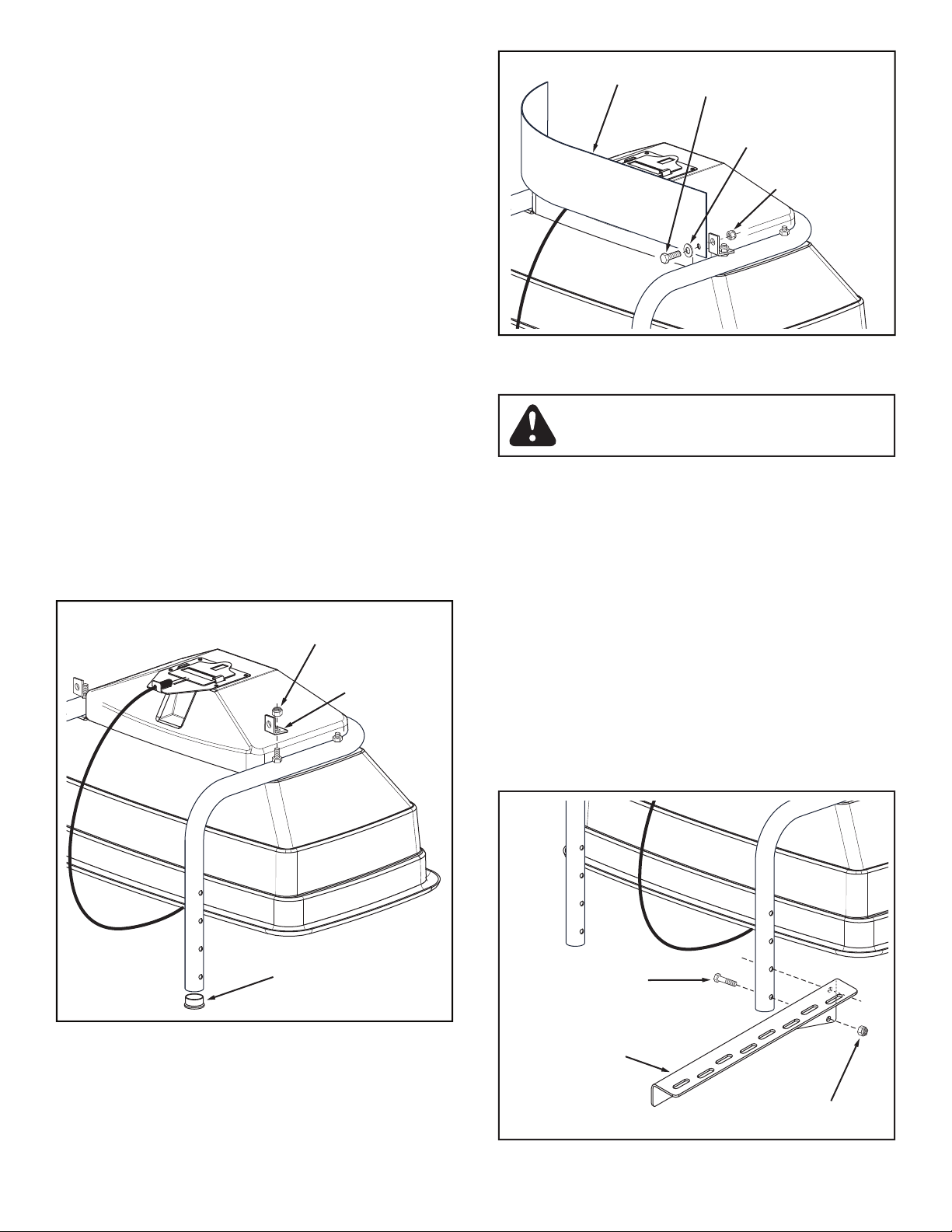
x 3/4" hex bolts, 1/4" fl at washers and 1/4" nylock nuts.
Allow the angle brackets to swivel so that the defl ector
tighten all nuts
1/4" NYLOCK
NUT
1/4" FLAT
WASHER
1/4" x 3/4"
HEX BOLT
DEFLECTOR
ANGLE
BRACKET
1/4" NYLOCK
NUT
PLUG
5/16" x 1-2"
HEX BOLT
5/16" NYLOCK NUT
MOUNTING
BRACKET, R.H.
The top of the hopper should be at least 30" above
the ground. The mounting holes shown in fi gures 3 and 4
will make the top of the hopper even with the vehicle's rear
Position the spreader for adequate clearance if
the vehicle muffl er discharges straight toward
the rear.
Before proceeding, determine if the mounting
fi t onto the vehicle rack. If they need to be farther apart, use
the extension brackets in fi gure 4.
Tighten.
Repeat for the L.H. mounting
Page 5

frame. Use two 5/16" x 2" hex bolts and 5/16" nylock
Tighten.
See fi gure 4.
5/16" NYLOCK
NUT
MOUNTING
BRACKET, R.H.
5/16" x 1"
HEX BOLT
Tighten.
Repeat on the other frame
5/16" x 1-3/4"
CARRIAGE BOLT
MOUNTING
CLAMP
PLASTIC KNOB
MOUNTING
BRACKET
ADHESIVE PAD
5/16" x 2"
HEX BOLT
EXTENSION
BRACKET
5/16" NYLOCK NUT
IMPELLER
1/8" x 1-1/4"
COTTER PIN
1/8" HAIRPIN
AGITATOR
SEAL
SPREADER
SHAFT
the spreader shaft. Assemble a seal (turned as shown
to the hairpin agitator. See fi gure 7.
through the plastic bushing in the bottom of the hopper.
Page 6

place
fi gure 9.
the end of the spreader shaft into the impeller coupler.
5/16" x 1"
HEX BOLT
NYLON
WASHER
5/16" NYLOCK NUT
MOTOR
ASSEMBLY
5/16" FLAT
WASHER
SCREEN
1/8" x 1-1/4"
COTTER PIN
SPREADER
SHAFT
Then, slightly bow the screen to slide the opposite side
CLIPS
CLIP
SCREEN
SHAFT
SEAL
BUSHING
1/8" x 1-1/4"
COTTER PIN
SEAL
IMPELLER
COUPLER
Page 7

WIRING INSTRUCTIONS
When properly connected, the spreader motor and impeller
will run
The wire harness may be left permanently attached to
the battery. See fi gure 12.
the brown and white wires to the spreader motor. Refer
to fi gure 12.
You can also attach to the rear rack if you use a 5/16"
x 1-3/4" carriage bolt. If you attach to the rear rack, you can
"ON-OFF"
SWITCH
FLOW CONTROL
ON-OFF
the "ON-OFF" switch on and check that the motor
the "ON-OFF" switch off. If it does not, you can loosen
the control and rotate it enough that the fl ow control
BROWN
RED
FUSE AND HOLDER
POSITIVE
"HOT" POST
NEGATIVE PIN
BROWN
RED
BATTERY
+
SWITCH
MOTOR
BROWN
RED
WHITE
5/16" x 1"
CARRIAGE
BOLT
MOUNTING
CLAMP
PLASTIC KNOB
5/16" x 1-3/4"
CARRIAGE
BOLT
Page 8

Application rates shown in the chart are
the material (granular and pellet). Some minor setting
OVERLAP
REFER
TO CHART
We do not recommend the use of any powdered lawn
the fl ow control is operating properly.
the fl ow control arm in the off position. Refer to the
the Adjustable Stop, locking the lever at the desired
5
1
3
7
10
OFF
FLOW CONTROL LEVER
ADJUSTABLE STOP
the application chart on this page.
the broadcast pattern does not hit evergreen trees,
fl owers or shrubs.
wind and moisture shield, but should not be used as a
TYPE FLOW SETTING SPREAD
MATERIAL 3 MPH WIDTH
APPLICATION CHART
Powder 3 - 5 3' - 4'
Granular 3 - 5 10' - 12'
Pelleted 3 - 5 17' - 19'
Organic 6 - 8 3' - 4'
GRASS SEED
Fine 3 - 4 3' - 4'
Coarse 4 - 5 8' - 9'
ICE MELTER 6 - 8 17' - 19'
SAND 4-10 17' - 19'
Page 9

wiring
the correct position.
Page 10

44
43
38
36
36
45
34
35
39
40
41
42
22
25
4
6
5
55
3
6
5
21
33
35
1
7
7
7
27
47
46
7
24
26
9
8
31
5
37
30, 51
29
12
15
14
16
11
52
28
17
36
10
2
6
20
18
27
30
29
28
49
48
31
22
23
23
22
19
50
54
32
53
Page 11

REF. PART QTY. DESCRIPTION
NO. NO.
1 48915 1 Hopper
2 48402 2 Plastic Plug
3 45164 2 Hex Bolt, 1/4-20 x 2-1/4"
4 46699 4 Hex Bolt, 1/4-20 x 2"
5 1543-69 10 Nylon Washer
6 43088 8 Flat Washer, 1/4"
7 47189 10 Nylock Nut, 1/4-20
8 25118 1 Flow Slide
9 24853 1 Guide Plate
10 43882 4 Rivet, Stainless Steel
11 47999 1 Control Cable Assembly
12 24937 1 Control Mount Bracket
14 46978 1 Hex Nut, 1/4-20 (SIMS)
15 48983 1 Switch, On-Off
16 44732 1 Star Washer
17 45082 1 Boot, Rubber Switch
18 48947 1 Tube, Hopper Mount
19 44180 4 Hex Bolt, 5/16-18 x 2"
20 726-0178 3 Nylon Tie
21 48934 1 Hairpin Agitator
22 47810 12 Nylock Nut, 5/16-18
23 25248 2 Extension Bracket
24 43012 2 Hex Bolt, 1/4-20 x 3/4"
25 24946 1 Impeller Shaft
26 47674 2 Plug, 1-1/4"
27 23826 2 Angle Bracket
28 43720 5 Plastic Knob
29 23442 5 Mounting Bracket
30 44215 5 Carriage Bolt, 5/16-18 x 1-3/4"
REF. PART QTY. DESCRIPTION
NO. NO.
31 43063 8 Hex Bolt, 5/16-18 x 1"
32 43081 4 Flat Washer, 5/16"
33 44285 1 Bushing, Hopper
34 24884 1 Coupler, Impeller
35 48577 2 Shaft Seal
36 43010 3 Cotter Pin, 1/8" x 1-1/4"
37 46554 1 Wire Harness
38 24936 1 Bracket, Motor Mount
39 46562 1 Motor
40 46334 4 Pan Head Bolt, #8-32 x 1/2"
41 736-0722 4 Lock Washer, #10
42 43910 4 Flat Washer, #10
43 48432 1 Cover, Motor
44 43346 2 Truss Head Bolt, #10-32 x 5/8"
45 47171 2 Nylock Nut, #10-32
46 04367 1 Impeller
47 48559 1 Defl ector
48 25214 1 Mounting Bracket, R.H.
49 25213 1 Mounting Bracket, L.H.
50 49080 1 Vinyl Cover
51 44326 1 Carriage Bolt, 5/16-18 x 1"
52 45039 1 Carriage Bolt, 1/4-20 x 1-3/4"
53 48661 4 Adhesive Pad
54
55
48581 1 Owner's Manual
the fastest way to purchase parts
www.speedepart.com
Page 12

Agri-Fab, Inc.
www.agri-fab.com
the fastest way to purchase parts
www.speedepart.com
© 2004 Agri-Fab, Inc.
 Loading...