

Page 1
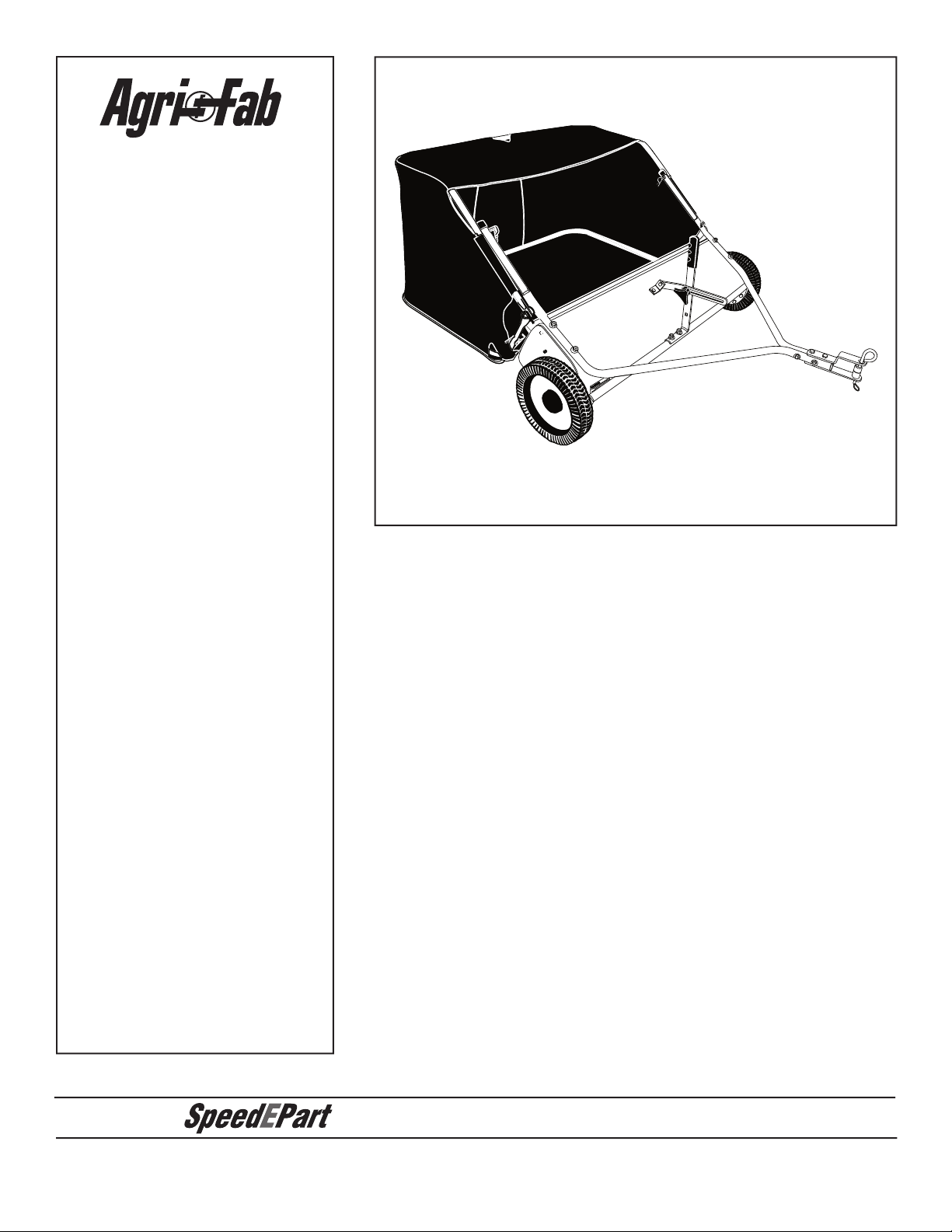
ATTENTION:
™
the fastest way to purchase parts
www.speedepart.com
Page 2
1
2
3
4
5
6
7
8
2
17
16
11
11
13
14
12
12
13
15
9
10
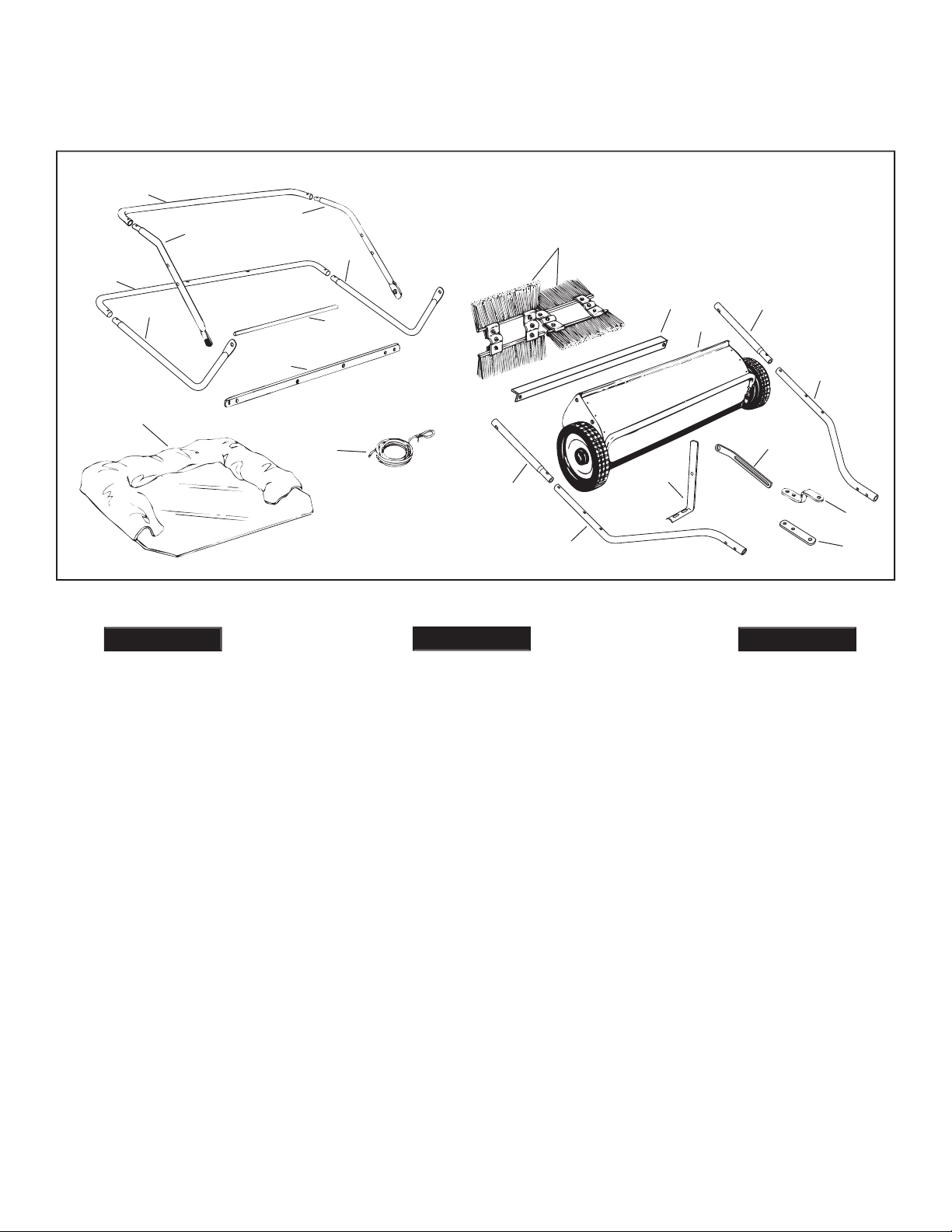
la Tolva (2)
la Tolva (2)
trémie (2)
trémie (2)
(Partes Sueltas en la Caja)
(Pièces en Vrac Dans le Carton)
ENGLISH
ESPAÑOL
FRANÇAIS
Page 3
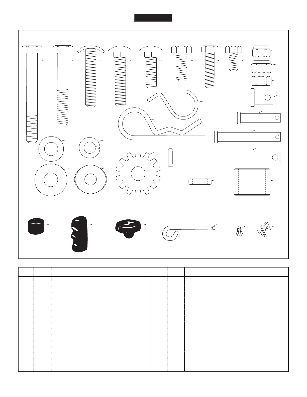
REF. QTY. DESCRIPTION
P 1 Lock Washer (Tooth), 5/16"
Q 1 Hair Cotter Pin, 1/8"
R 8 Hair Cotter Pin, 3/32"
S 2 Clevis Pin, 3/8" x 1/2"
T 2 Clevis Pin, 1/4" x 1-1/8"
U 2 Clevis Pin, 1/4" x 1-3/4"
V 2 Clevis Pin, 3/8" x 3"
W 1 Spacer Bushing,
X 2 Hitch Spacer, 3/4"
Y 2 Vinyl Cap
Z 1 Grip
AA 1 Knob, Plastic
BB 1 Hitch Pin
CC 4 Plastic Plug
DD 1 Angle Bracket
A 2 Hex Bolt, 5/16 x 2-1/2" Lg.
B 2 Hex Bolt, 5/16 x 2" Lg.
C 2 Curved Head Bolt, 5/16" x 1-5/8"
D 4 Carriage Bolt, 5/16" x 1-1/2"
E 1 Carriage Bolt, 5/16 x 1" Lg.
F 2 Hex Bolt, 5/16" x 3/4"
G 4 Hex Bolt, 1/4" x 1"
H 2 Hex Bolt, 1/4" x 1/2"
I 6 Nylock Nut, 1/4"
J 10 Nylock Nut, 5/16"
K 2 Hex Nut (Plain), 5/16"
L 2 Flat Washer, 5/16" (Small)
M 2 Flat Washer, 5/16" Std. Wrt.
N 2 Lock Washer, 5/16"
O 2 Bowed Washer
A B C
D
F G H
I
J
K
Q
R
N
L
M
Y Z AA
BB
P
U
W X
SHOWN FULL SIZE
NOT SHOWN FULL SIZE
T
S
CC
E
V
O
DD
ENGLISH
Page 4

the attachment of this sweeper. Do not fi ll sweeper to
towing vehicle to safely pull and stop with the sweeper
the bag and its contents to burn.
terrain, near ditches and on hillsides to prevent loss of
the equipment. Exercise caution at all times when using power equipment.
Your safety is involved.
ENGLISH
Page 5
TOOLS REQUIRED FOR ASSEMBLY
All loose parts are shown on page 2. Fasteners in the parts
Right hand (R.H.) and left hand (L.H.) are determined
from the operator's position while seated on the tractor.
ENGLISH
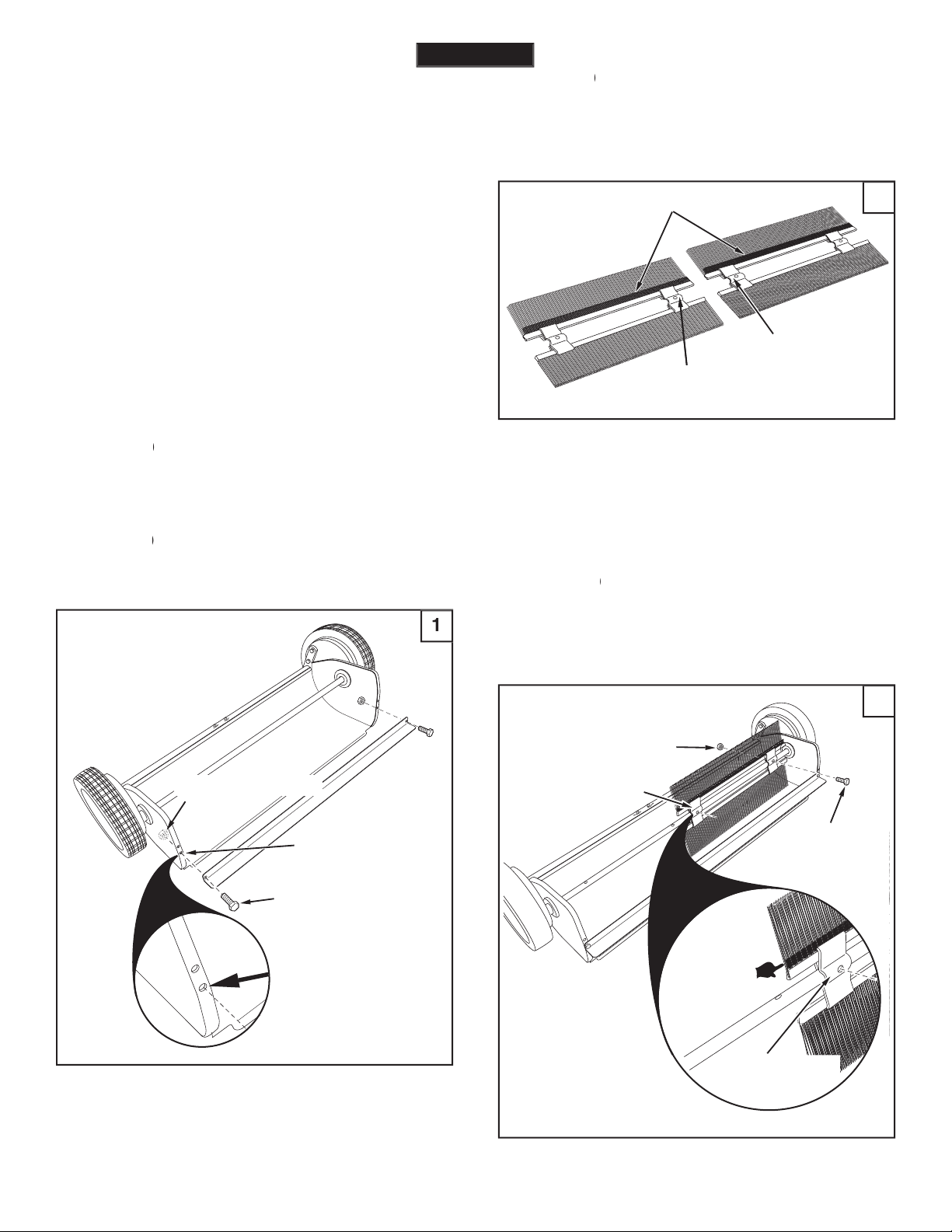
1/4" x 1/2"
HEX BOLT (H)
1/4" NYLOCK NUT (I)
USE THIS HOLE
with ink are in the middle with the red one on the right
OVERLAP BRISTLES
BRUSH RETAINER
MARKED BLACK
BRUSH RETAINER
MARKED RED
The overlap bristles at the bottom of each brush
fi gures 2 and 3 to correctly assemble the brushes.
two 1/4" x 1" hex bolts (G) and 1/4" nylock nuts (I). The
the
of the sweeper.
BRUSH RETAINER
MARKED RED
OVERLAP
BRISTLES
1/4" x 1"
HEX BOLT (G)
1/4" NYLOCK NUT (I)
BRUSH RETAINER
MARKED RED
Page 6
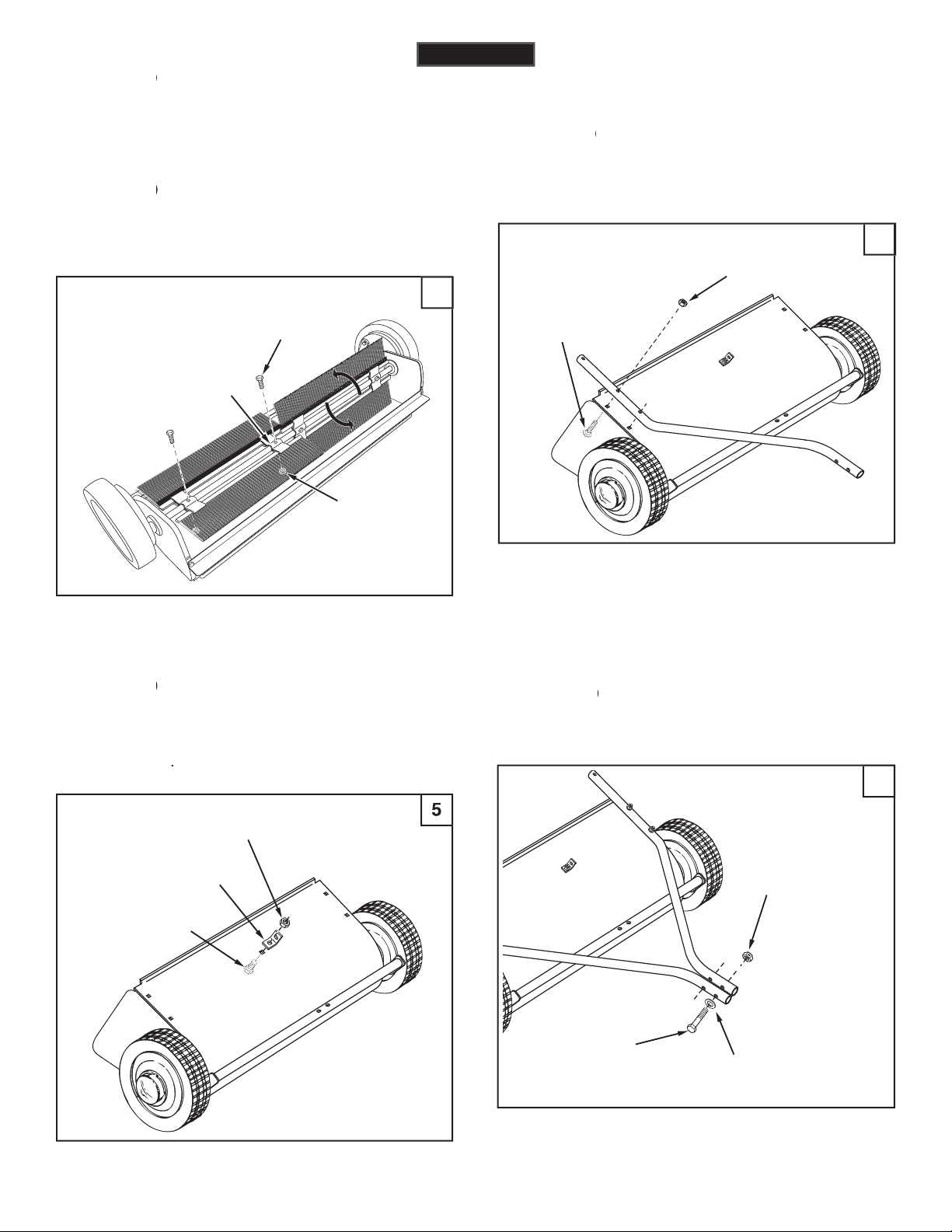
Assemble the angle bracket (DD) to the
then
tighten
5/16" x 3/4"
HEX BOLT (F)
5/16"
NYLOCK NUT (J)
ANGLE
BRACKET (DD)
5/16" x 1-1/2"
CARRIAGE BOLT (D)
5/16" NYLOCK NUT (J)
tube in place.
two 5/16" nylock nuts (J).
for the L.H. hitch tube.
Fasten the hitch tubes together using two
5/16" x 2-1/2"
HEX BOLT (A)
5/16"
NYLOCK NUT (J)
5/16" SMALL FLAT
WASHER (L)
two 1/4" x 1" hex bolts (G) and 1/4" nylock nuts (I). The
the
of the sweeper.
wheels drive the brushes in one direction only.) The
1/4" x 1"
HEX BOLT (G)
1/4" NYLOCK NUT (I)
BRUSH RETAINER
MARKED BLACK
ENGLISH
Page 7
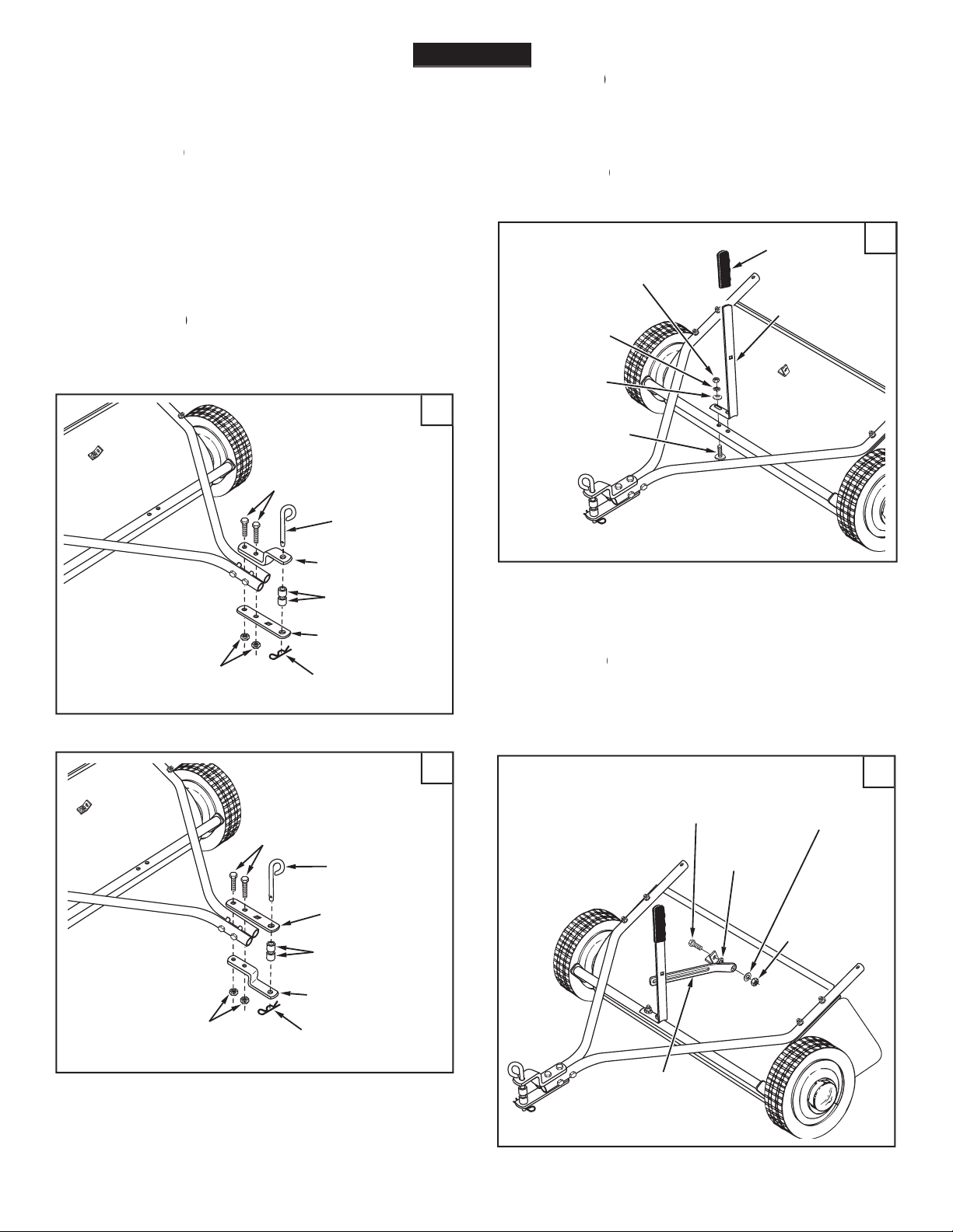
Assemble the height adjustment handle to
the height adjustment tube as shown in fi gure six. Use
two curved head bolts (C), bowed washers (O), 5/16"
yet.
Assemble the grip (Z) onto the height
Insert a 5/16" x 3/4" hex bolt (F) through
the angle bracket. Assemble onto the bolt (in order) the
fl at washer (M) and a 5/16" nylock nut (J).
Tighten.
to fi gure 8. If your tractor hitch has 8" to 10" ground
tubes using two 5/16" x 2" hex bolts (B) and 5/16" nylock
tighten
the four bolts fastening the hitch
tubes to the sweeper housing. Next,
tighten
the two bolts
fastening the ends of the hitch tubes together. Finally,
tighten
the two bolts fastening the hitch brackets to the
Assemble the hitch pin (BB), two 3/4"
5/16" x 2"
HEX BOLT (B)
5/16" HEX
LOCK NUT (J)
3/4" SPACER (X)
HITCH BRACKET
HITCH BRACKET
(STRAIGHT)
1/8" HAIR
COTTER PIN (Q)
HITCH PIN (BB)
CURVED
HEAD BOLT (C)
5/16" HEX NUT (K)
BOWED
WASHER (O)
5/16" LOCK
WASHER (N)
HEIGHT
ADJUSTMENT
HANDLE
GRIP (Z)
5/16" x 2"
HEX BOLT (B)
5/16"
NYLOCK NUT (J)
3/4" SPACER (X)
HITCH PIN (BB)
HITCH BRACKET
(STRAIGHT)
1/8" HAIR
COTTER PIN (Q)
HITCH BRACKET
ENGLISH
5/16" NYLOCK
NUT (J)
5/16" FLAT
WASHER (M)
HEIGHT
ADJUSTMENT
STRAP
5/16" x 3/4"
HEX BOLT (F)
SPACER
BUSHING (W)
Page 8
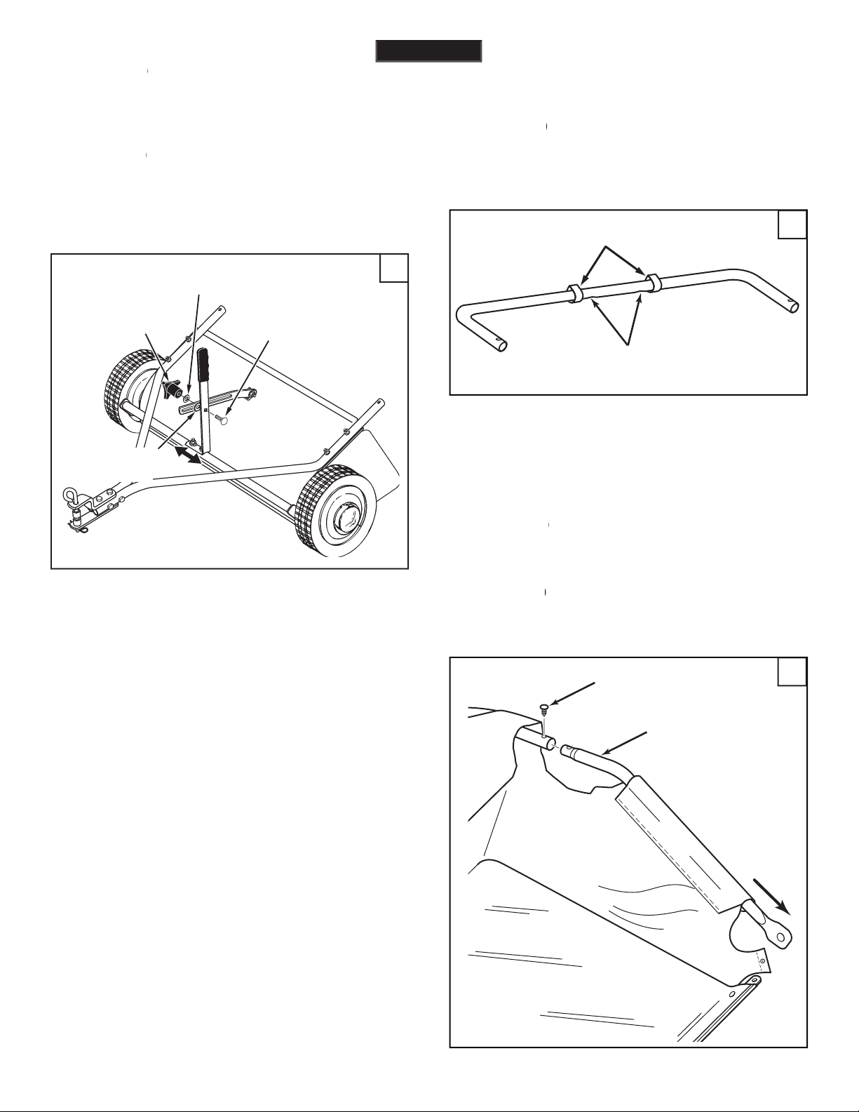
Position the height adjustment handle side
to side so that the tooth lock washer (P) can fi t between
the handle and the height adjustment strap.
Tighten
the
Insert the 5/16" x 1" carriage bolt (E) through
the height adjustment handle. Assemble onto the bolt,
face down
tube through the two loops sewn to the top rear seam
through the stitched fl aps on each side of the hopper
together using plastic plugs (CC).
UPPER HOPPER
SIDE TUBE
PLASTIC PLUG (CC)
REAR HOPPER TUBE
(brace holes on bottom)
INNER BAG LOOPS
ENGLISH
5/16" x 1"
CARRIAGE BOLT (E)
TOOTH LOCK
WASHER (P)
PLASTIC
KNOB (AA)
5/16" FLAT
WASHER (M)
Page 9
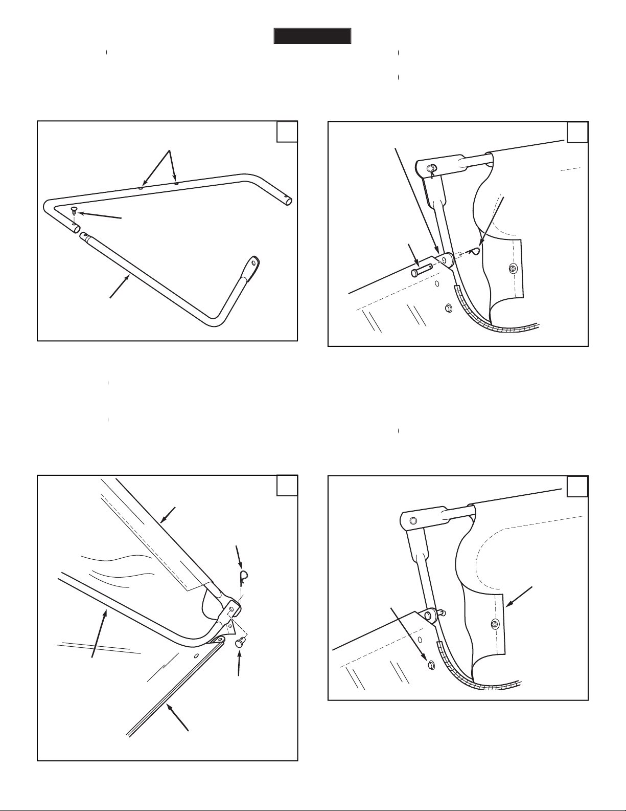
Insert the bag frame strap into the stitched
Assemble the bag frame strap to the lower
SNAP
FLAP
Secure the bag corners around the lower
face up
the ends of the rear hopper tube onto the ends of the
tubes to the
of the upper hopper side tubes using
two 3/8" x 1/2" clevis pins (S) inserted from the inside,
LOWER
HOPPER
SIDE TUBE
PLASTIC PLUG (CC)
REAR HOPPER TUBE
(brace holes on top)
LOWER HOPPER
SIDE TUBE
HOPPER BAG
BOTTOM
UPPER HOPPER
SIDE TUBE
3/8" x 1/2"
CLEVIS PIN (S)
3/32" HAIR
COTTER PIN (R)
1/4" x 1-1/8"
CLEVIS PIN (T)
3/32" HAIR
COTTER PIN (R)
BAG FRAME STRAP
ENGLISH
Page 10

over bend the support rods during
the following step. Over bending will cause the steel rods
to loose supporting tension.
the two hopper support rods. Place the ends of each
the rod just enough to fi t into the holes in the tubes.
Insert a 3/8" x 3" clevis pin (V) through
the
hole in each upper hopper side tube. Next
SUPPORT
RODS
Secure the rope to the top center of the
To assemble the hopper bag to the sweeper,
LOWER HOLE
3/32" HAIR
COTTER PIN (R)
3/8" x 3"
CLEVIS PIN (V)
BAG ARM TUBE
VINYL CAP (Y)
BAG ARM TUBE
1/4" x 1-3/4"
CLEVIS PIN (U)
3/32" HAIR
COTTER PIN (R)
ENGLISH
Page 11

the ground. See fi gure 24 for tractor hitches that are
For best performance, the bottom of the
the ground as shown in fi gure 23.
Tractor hitches with 8" to 10" ground clearance.
Tractor hitches with 10" to 13" ground clearance.
TRACTOR HITCH
8"-10"
TRACTOR HITCH
10"-13"
ENGLISH
5" Min.
Page 12

HEX BOLT FLAT WASHER
FLAT WASHER
HEX LOCK NUT
HUB CAP
SPACER
HEIGHT ADJUSTMENT SLOT
HEX BOLT
OIL BEARINGS HERE
FLAT WASHER
To adjust your sweeper brushes to the best operating
the grass. Always mow the grass to an even height
Try a starting speed of approximately 3 m.p.h. (third
Your sweeper can be dumped easily without getting
to dump the hopper. Always empty hopper after each
Keep sweeper away from fi re.
the hopper rope
to any part of your body or clothing!
the rope while towing the sweeper!
to the towing vehicle to keep
a. Clean sweeper housing with a soft brush or cloth.
b. Clean debris from hopper bag with a brush or
broom.
c. Remove any material which has wrapped around
the hub cap and apply a few drops of light weight oil.
the sweeper,
Lubricate the brush shaft bearing twice a
year with a few drops of light weight oil.
ENGLISH
Page 13

WHEEL GEAR AND PAWL SERVICE
remove both wheels at the same
time to avoid mixing of parts. (The R.H. and L.H. ratchet
on the position
wheel from the sweeper.
Remove the gear by sliding it off the brush
during forward rotation of the wheel. If the
Brush replacement should be done one brush at
a time.
or remove the
Slide the brush out of the retainers, noting
Install new brush, making sure the bristles
Wheels skid when sweeping.
ENGLISH
BRUSH ROTATION
BRUSH ROTATION
OVERLAP
BRISTLES
OVERLAP
BRISTLES
SINGLE
BRUSH
RETAINERS
DOUBLE BRUSH RETAINER
BRUSH
SHAFT
RATCHET
GEAR
DRIVE
PIN
Page 14

Page 15

verifi car la capacidad del vehículo de arrastre para
No opere en cuestas empinadas.
y causar el incendio de la bolsa y su contenido.
vehículo de arrastre y conozca su operación antes de
y partes rotatorias.
Su
ESPAÑOL
Page 16

Todas las partes sueltas se muestran en la página 2. Los sujetadores
verifi que que todas las partes y sujetadores que se muestran en
las fi guras del armado se encuentran en las páginas de
Instale el puntal de apoyo de atrás en los huecos
El traslape de cerdas en la parte de abajo de cada
Gire una rueda para hacer girar los cepillos. (Las
traslape de las cerdas debe quedar en el lado de atrás del
Fije la ménsula de ángulo (DD) en la carcaza de
y alineada recta con la carcaza y luego
Fije el tubo de enganche de mano derecha en la
y tuercas hexagonales (J).
No apriete todavía.
Repita la
Conecte entre si los tubos de enganche, usando
y tuercas de cierre (J).
Monte las ménsulas de enganche en los tubos
Todavía no apriete.
los cuatro pernos, fi jando los
tubos de enganche a la carcaza de la barredora. En seguida
los dos pernos, juntando los extremos de los tubos
los dos pernos, fi jando las
Monte el pasador de enganche (BB), dos
Inserte un perno hexagonal (F) a través de la
Apriete.
Coloque la manija de ajuste de altura, lado a lado,
Apriete
Inserte el perno de coche (E) a través de la
(Figura 13)
Haga girar el tubo del respaldo de la tolva, de
(Figura 14)
tolva, a través de los faldones cosidos con puntos a cada lado
Voltee el segundo tubo trasero de la tolva, de
Coloque los tubos de la parte inferior de la tolva
(Figura 16)
de los tubos laterales superiores de la
tolva, usando dos pasadores de grillete (S) insertados desde
ESPAÑOL
Page 17

tubos laterales inferiores de la tolva, usando dos pasadores
Asegure las esquinas de la bolsa alrededor de los
tubos laterales inferiores de la tolva, abrochando los faldones
No curve demasiado las barras de soporte durante
trasera de la tolva, curvando la barra apenas lo sufi ciente
Inserte un pasador de grillete (V) a través del hueco
Coloque una tapa de vinilo (Y) en el extremo de
Asegure la cuerda a la parte superior del centro
y asegúrelos con dos pasadores de grillete (U) y pasadores
y nivelada.
Para un mejor desempeño, el fondo de la bolsa de
Page 18

tolva a ninguna parte de su cuerpo ni de su ropa!
Amarre la cuerda
al vehículo de
y de las partes giratorias.
Cada dos años retire las ruedas y limpie los
a. Limpie la carcaza de la barredora con un cepillo suave
b. Limpie los residuos de la bolsa de la tolva con una
escoba o con un cepillo.
c. Retire cualquier material que se haya enrollado
alrededor de los cepillos o los terminales del eje del
cepillo.
tales como cepillos y ruedas, antes de cada uso. Reemplace
ESPAÑOL
AJUSTE DE LA ALTURA DEL CEPILLO
Para ajustar los cepillos de su barredora en la mejor altura
VELOCIDAD DE BARRIDO
Ensaye una velocidad inicial de aproximadamente 3 millas
VACIADO DE LA BARREDORA
Su barredora se puede vaciar fácilmente sin necesidad de
tolva. Siempre vacíe la tolva después de cada uso.
fuego. El calor excesivo puede dañar los cepillos
y la bolsa de la tolva, y puede hacer que la bolsa
y su contenido se incendien.
RANURA DE AJUSTE DE ALTURA
PERNO HEXAGONAL
ACEITE AQUI
LOS COJINETES
ARANDELA PLANA
PERNO HEXAGONAL
ARANDELA PLANA
ARANDELA PLANA
CONTRATUERCA HEXAGONAL
TAPA
DEL
CUBO
ESPACIADOR
la barredora,
Page 19

Y DEL TRINQUETE
Anote
la posición de las arandelas y de los anillos a presión
a la vez de la barredora.
Retire el engranaje deslizándolo fuera del eje
trinquete).
trinquete.
graduados demasiado abajo
atascadas
dentro del césped
Consulte la Sección de Servicio y Ajustes.
El cambio de cepillos deberá hacerse uno por uno.
Afl oje los pernos hexagonales y las tuercas de
ni
Saque deslizando el cepillo de los retenedores,
fi jándose bien en qué lado del cepillo se superponen las
Instale el cepillo nuevo, asegurándose de que las
ESPAÑOL
ROTACION
DEL CEPILLO
ROTACION
DEL CEPILLO
SUPERPOSICION
DE LAS CERDAS
SUPERPOSICION
DE LAS CERDAS
RETENEDORES
DEL CEPILLO
SENCILLO
RETENEDOR DEL
CEPILLO DOBLE
EJE DEL
CEPILLO
ENGRANAJE
DEL TRINQUETE
PASADOR IMPULSOR
Page 20

Page 21

vous des pentes raides.
tracteur afi n de l’éloigner des roues et des pièces en
terrains cahoteux, à proximité de tranchées et sur des
Tout appareil mécanique utilisé incorrectement peut être la cause de blessures. L’utilisateur doit bien en maîtriser le
fonctionnement. Observez en tout temps la plus grande prudence lorsque vous utilisez un appareil mécanique.
FRANÇAIS
Page 22

FRANÇAIS
Toutes les pièces mobiles sont présentées en page 2. Les organes
La droite et la gauche sont déterminées par rapport
Les fi gures à propos du montage se trouvent sur
Placez la plaque en carton que vous avez retiré de
Fixez la barre de support arrière sur les trous
Chaque brosse possède une pièce de retenue
Les soies se chevauchant en bas de chaque
Fixez les brosses comportant la pièce de retenue
frein élastique (I). La pièce de retenue de la brosse indiquée
Fixez les brosses comportant la pièce de retenue
frein élastique (I). La pièce de retenue de la brosse indiquée
Montez le support d’angle sur le bâti de la balayeuse
Assemblez le tube d’attelage droit au bâti de la
Serrez ensemble les tube d’attelage en utilisant
Assemblez les supports d’attelage aux tubes
Assemblez la cheville d’attelage (BB), deux
Assemblez la poignée de réglage de la hauteur
tête ronde (C), des rondelles bombées (O), des rondelles de
Assemblez le système de préhension (Z) dans
Insérez un boulon hexagonal (F) à travers le
Positionnez la poignée de réglage de la hauteur
Insérez le boulon de carrosserie (E) à travers la
Page 23

Faites tourner un des tubes arrière de trémie de
vers le bas. Faites glisser le tube à travers les deux boucles
Insérez les deux tubes latéraux supérieurs de la
trémie à travers les panneaux cousus de chaque côté du sac
Assemblez les extrémités du tube arrière de la
trémie dans les extrémités des tubes latéraux supérieurs de
Faites tourner le deuxième tube arrière de trémie
vers le haut. Assemblez les extrémités du tube arrière de la
trémie dans les extrémités des tubes latéraux inférieurs de
Placez les tubes arrière inférieurs assemblés de
Attachez les extrémités des tubes latéraux
Insérez la bride du cadre du sac dans le manchon
tubes latéraux
Ne cintrez pas à l’excès les tiges de support au
Inclinez la trémie dans sa partie arrière afi n
Insérez une goupille (V) dans le trou inférieur de
Insérez un bouchon en vinyle (Y) à l’extrémité de
Attachez le cordage en partie centrale supérieure
Pour assembler le sac de récupération des débris,
faites glisser les extrémités et des tubes du bras du sac dans
fendues (R).
TRACTEUR
Afi n de bénéfi cier des meilleures performances,
FRANÇAIS
Page 24

FRANÇAIS
ATTENTION:
le cordage de la
trémie à votre corps ou à vos vêtements !
jamais
le cordage en tractant la balayeuse !
au véhicule tracteur afi n de l’éloigner
Tous les deux ans, démontez les roues et nettoyez
Après nettoyage, graissez les engrenages avec une graisse
Vérifi ez que les organes de fi xation sont serrés avant chaque
a. Nettoyez le bâti de la balayeuse avec une brosse
souple ou avec un chiffon.
b. Nettoyez les débris du sac de récupération avec une
brosse ou avec un balai.
c. Éliminez les débris pouvant s’être enroulés autour des
brosses ou aux extrémités de l’axe de ces dernières
Graissez les roulements de l’axe de la brosse
fonctionnement adéquate, desserrez le bouton de réglage et
VITESSE DE BALAYAGE
Essayez une vitesse de 3 miles/h (5 km/h) environ pour
fonction des conditions, il peut s’avérer nécessaire de régler
Votre balayeuse peut-être facilement vidée sans descendre
trémie. Videz toujours la trémie après chaque utilisation.
ATTENTION:
Éloignez la balayeuse de toute
FENTE DE RƒGLAGE DE LA HAUTEUR
BOULON HEXAGONAL
GRAISSER ICI
LES ROULEMENTS
RONDELLE PLATE
BOULON HEXAGONAL
RONDELLE PLATE
RONDELLE PLATE
ÉCROU DE BLOCAGE HEXAGONAL
CAPUCHON DE MOYEU
ENTRETOISE
ATTENTION
Avant d’entreposer la balayeuse,
videz toujours le sac de récupération des débris
Page 25

les deux roues simultanément
roue à la fois.
Déposez l’engrenage en le faisant glisser en
Assurez-vous que la broche glisse facilement de part et d’autre
tourner pendant la rotation vers l’avant de la roue.
trop bas.
à 1,2 cm dans l’herbe.
d’une obstruction ou d’une détérioration. Reportez-vous à
la section Entretien et réglages.
Desserrez les boulons hexagonaux et les écrous
Faites glisser la brosse en dehors des pattes de
fi xation en notant le côté de la brosse sur lequel se chevauchent
SENS DE ROTATION
DE LA BROSSE
SENS DE ROTATION
DE LA BROSSE
LES POILS SE
CHEVAUCHENT
LES POILS SE
CHEVAUCHENT
PATTES DE
FIXATION
D'UNE
BROSSE
PATTE DE FIXATION
DES DEUX BROSSES
AXE DE
LA BROSSE
ENGRENAGE À CLIQUET
GOUPILLE D'ENTRA
ÎNEMENT
FRANÇAIS
Page 26

C
B
B
C
D
1
2
3
4
5
6
7
8
11
17
18
19
20
21
22
23
23
24
25
26
26
27
29
29
29
30
31
32
33
33
35
36
37
38
39
41
42
43
43
55
56
60
61
60
61
63
62
66
72
73
74
75
76
34
34
7
28
12
13
D
29
65
9
10
9
29
25
E
53
75
44
45
46
44
46
48
50
51
58
58
77
49
53
45
47
59
75
59
75
75
52
47
71
54
67
69
29
69
39
A
E
57
68
70
15
16
14
A
35
Page 27

No. No.
1 48306 1 Hitch Tube, R.H.
2 48305 1 Hitch Tube, L.H.
3 24950 1 End Plate, R.H.
4 24951 1 End Plate, L.H.
5 24869 1 Wrapper
6
7 C-9M5732 14 Rivet, Pop
8 24185 1 Brace, Rear Support
9 43182 2 Bolt, Hex 5/16-18 x 3/4"
10 23826 1 Bracket, Angle
11 23336 2 Washer, Special
12 64540 1 Height Adjustment Tube Assembly
13 44947 2 Bolt, Cvd. Hd. 5/16-18 x 1-5/8" Lg.
14 44695 2 Washer, Bowed 1" x .32" x .06"
15 43086 2 Lock Washer, 5/16"
16 43083 2 Nut, Hex 5/16-18 Thread
17 R19212113 2 Washer, 5/8" SAE
18 1629-56 2 Retainer, Dust Cover
19 44910 2 Bushing, Brush Shaft
20 24188 1 Brush Shaft
21 48557 4 Brush
22 43012 8 Bolt, Hex 1/4-20 x 3/4" Lg.
23 47189 14 Nut, Nylock 1/4-20
24 23580 4 Retainer, Brush (Double)
25 23581 8 Retainer, Brush (Single)
26 44008 2 Washer, Flat 1-1/8" x .78" x .025"
27 47046 2 Dowel Pin (Drive)
29 47810 14 Nut, Nylock 5/16-18
30 44911 2 Spacer, .39 I.D". x 1-1/4" O.D. x .5"
31 44006 2 Washer, Flat .849" x .598" x .025"
32 46219 2 Spacer, .78 I.D". x 1-1/4" O.D. x .5"
33 1650-21 4 Ring, Retaining .594"
34 44007 2 Washer, Shim 1-1/8" x .594" x .025"
35 141 4 Washer, Flat 1-1/2" x .375" x .062"
36 1038 2 Nut, Nylock Jam 3/8-24 Thread
37 2674-32 2 Hub Cap
38 44961 2 Bolt, Hex 3/8-24 x 3-1/4" Lg.
39 23400 3 Bushing, Spacer
40 48652 1 Gear, Pinion R.H. (not shown)
41 48651 1 Gear, Pinion L.H.
No. No.
42 43661 4 Bolt, Hex 1/4-20 x 1" Lg.
43 64559 2 Ass'y, Dust Cover
44 48587 2 Tube, Hopper Frame (Rear)
45 48466 2 Tube, Upper Hopper Frame (Front)
46 48726 2 Tube, Lower Hopper Frame (Front)
47 48402 4 Plastic Plug
48 48388 1 Hopper Bag
49 48366 2 Clevis Pin, 3/8" x 1/2"
50 24949 1 Strap, Bag Frame
51 43926 2 Rod, Hopper Support
52 43737 1 Hopper Rope
53 44481 2 Cap, Vinyl
54 24979 1 Strap, Height Adjustment
55 23687 1 Bracket, Hitch
56 24192 1 Bracket, Hitch (Straight)
57 23850 1 Handle, Height Adjustment
58 48323 2 Tube, Bag Arm
59 43513 2 Pin, Clevis 3/8" x 3"
60 44985 2 Wheel & Tire Ass'y. (with bearings)
61 45088 4 Wheel Bearing
62 44292 2 Bolt, Hex 5/16-18 x 2-1/2" Lg.
63 44180 2 Bolt, Hex 5/16-18 x 2" Lg.
65 43681 4 Bolt, Carriage 5/16-18 x 1-1/2"
66 R19111116 2 Washer, Flat (5/16) 11/32" x 11/16"
67 43720 1 Knob, Wing 5/16-18 Thread
68 44326 1 Bolt, Carriage 5/16-18 x 1"
69 43081 2 Washer, Flat 5/16" Std. Wrt.
70 43943 1 Grip, Height Adjust
71 44732 1 Washer, Tooth Lock 5/16"
72 23353 1 Pin, Hitch
73 23368 2 Tube, Hitch Spacer
74 43343 1 Hairpin Cotter, 1/8" #4
75 43055 8 Hairpin Cotter, 3/32" #3
76 46867 2 Clevis Pin, 1/4" x 1-3/4" Lg.
77 48365 2 Clevis Pin, 1/4" x 1-1/8"
49040 1 Owners Manual
the fastest way to purchase parts
www.speedepart.com
Page 28

the fastest way to purchase parts
www.speedepart.com
Agri-Fab, Inc.
www.agri-fab.com
© 2003 Agri-Fab, Inc.
 Loading...