

Page 1
OWNERS
BROADCAST
SPREADER
MANUAL
Model No.
45-02141
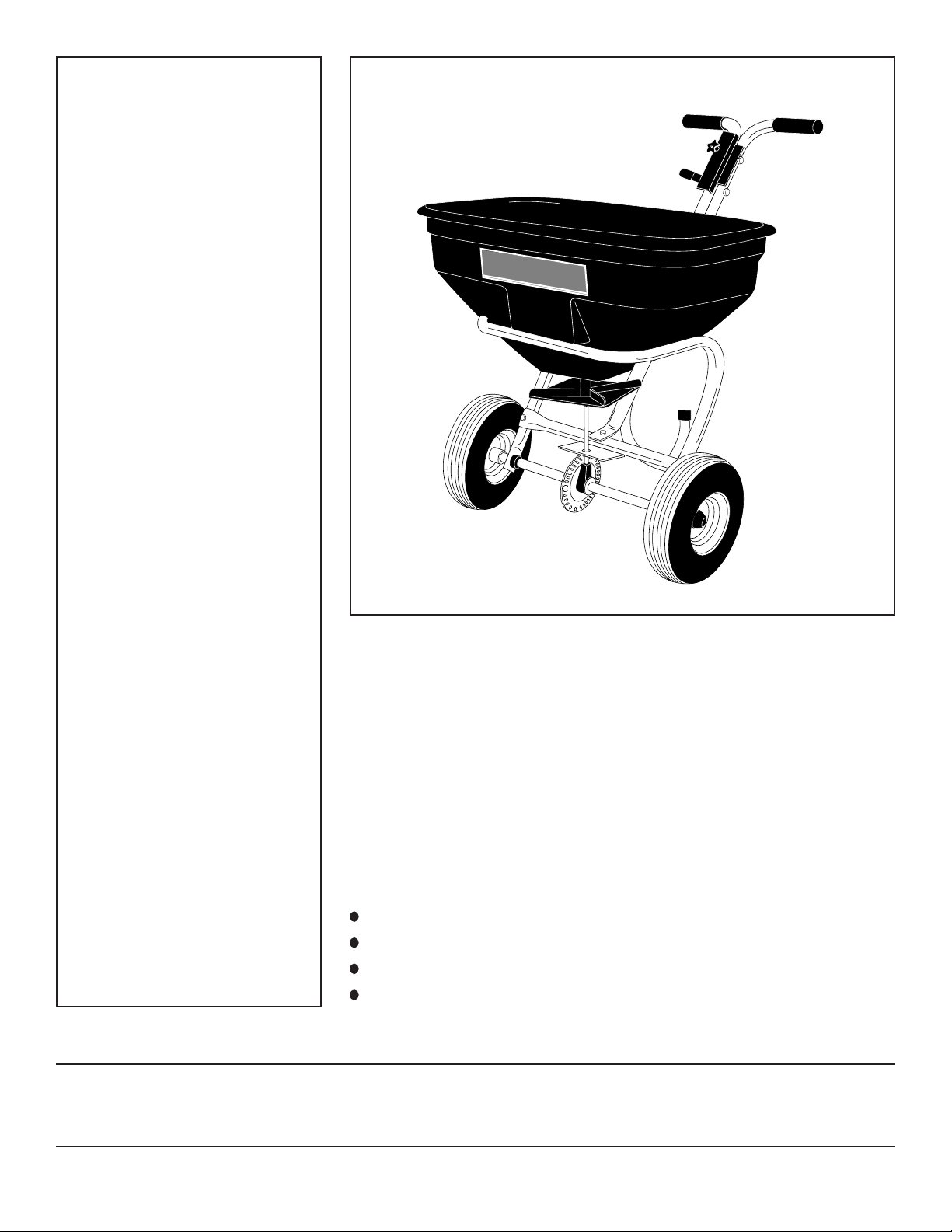
BROADCAST
SPREADER
BROADCAST SPREADER 100
(PUSH)
CAUTION:
Read Rules for
Safe Operation
and Instructions
PRINTED IN U.S.A. FORM NO. 47290 (REV. 12/01)
Carefully
Assembly
Operation
Maintenance
Repair Parts
Page 2
RULES FOR SAFE OPERATION
The following safety precautions are suggested. This
broadcast spreader is designed, engineered and tested
to offer reasonably safe and effective service, provided it
is operated in strict accordance with these instructions.
Failure to do so may result in personal injury. Always
observe the rules of safe operation.
1. Do not allow anyone to operate the broadcast
spreader without proper instructions.
2. Do not permit children to operate the broadcast
spreader.
LOOK FOR THIS SYMBOL TO POINT OUT
IMPORTANT SAFETY PRECAUTIONS. IT
MEANS -- ATTENTION! BECOME ALERT!
YOUR SAFETY IS INVOLVED.
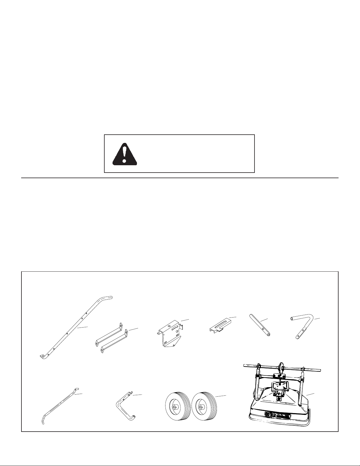
Your broadcast spreader carton contains parts as shown in figure 1. The hardware package contains parts shown
in figure 2 on page 3. Identify all parts and layout as shown in figures 1 and 2.
3. Wear eye and hand protection when handling and
when applying lawn or garden chemicals.
4. Read the chemical label instructions and cautions
for handling and applying the chemicals purchased
for spreading.
5. Keep all nuts, bolts and screws tight to be sure
equipment is in safe working condition.
6. Follow maintenance and lubrication instructions as
outlined in this manual.
CARTON CONTENTS
LOOSE PARTS IN CARTON
1. Handle Tube (long)
2. Braces
3. Flow Control Mount Bracket
4. Flow Control Gauge
5. Flow Control Arm
CARTON CONTENTS
1
6. Handle Tube (short)
7. Flow Control Rod
8. Leg Stand Tube
9. Wheels (2)
10. Hopper Assembly
11. Hardware Package (not shown)
3
2
4
5
6
FIGURE 1
7
8
2
9
10
Page 3
A
B
C
D
E
I
M
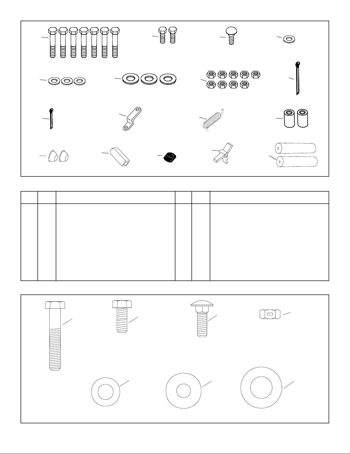
FIGURE 2 - HARDWARE PACKAGE
KEY QTY. DESCRIPTION
A 7 Hex Bolt, 1/4-20 x 1-1/2" Long
B 2 Hex Bolt, 1/4-20 x 5/8" Long
C 1 Carriage Bolt, 1/4-20 x 3/4" Long
D 1 Nylon Washer
E 3 Flat Washer, 5/16" SAE
F 3 Flat Washer, 1/2"
G 9 Hex Lock Nut, 1/4-20 Thd.
H 1 Cotter Pin, 5/32" x 2"
F
J
N
G
K
O
P
KEY QTY. DESCRIPTION
I 1 Cotter Pin, 3/32" x 3/4" Long
J 1 Flow Control Link
K 1 Extension Spring
L 2 Spacer Tube
M 2 Hub Cap
N 1 Grip
O 1 Vinyl Cap
P 1 Hand Knob
Q 2 Handle Grip
Q
H
L
A
1/4" x 5/8"
1/4" x 1-1/2"
E
5/16" WASHER
FULL SIZE HARDWARE REFERENCE CHART
B
C
G
1/4" LOCK NUT
1/4" x 3/4"
NYLON WASHER
3
D
1/2" WASHER
F
Page 4
ASSEMBLY INSTRUCTIONS
CROSSOVER
TUBE
1/4" HEX
BOLT
1/4" HEX
LOCK NUT
1/4" FLAT
WASHER
SHAFT
SUPPORT
TOOLS REQUIRED FOR ASSEMBLY
(1) Pliers
(1) Hammer
(2) 7/16" Open or Boxed End Wrenches
1. Remove the spreader, the loose parts and the hardware package from the carton. Lay out parts and
hardware and identify. Refer back to figures 1 and 2.
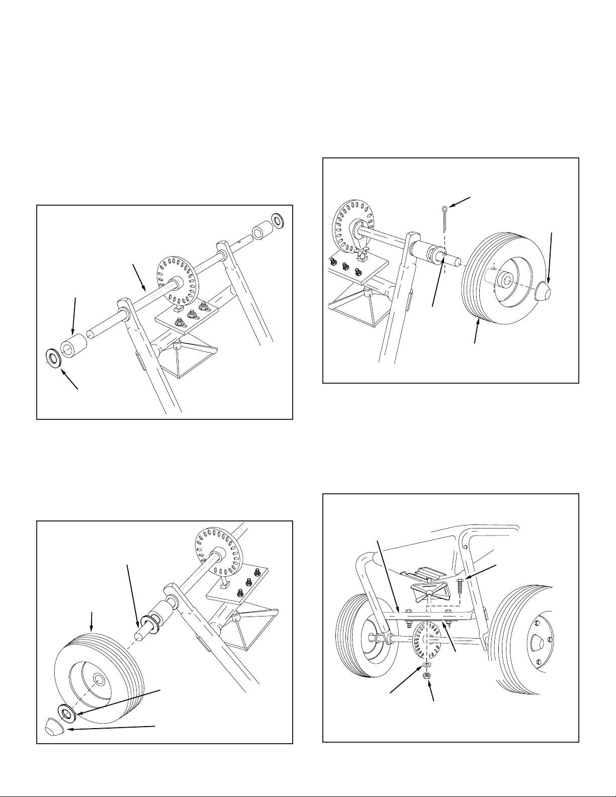
2. With the spreader resting upside down on the top of
the hopper, assemble a spacer and then a 1/2" flat
washer onto each end of the axle. See figure 3.
AXLE
SPACER
5. Place a wheel onto the end of the axle that has a cross
hole. The long end of the hub goes to the inside. See
figure 5.
6. Assemble a 5/32" x 2" cotter pin through the notched
wheel hub and the axle. See figure 5.
7. Lightly tap a hub cap onto the axle until it is snug
against the wheel. See figure 5.
5/32" x 2"
COTTER PIN
HUB CAP
CROSS
HOLE
1/2" FLAT
WASHER
FIGURE 3
3. Place a wheel onto the end of the axle that has no cross
hole. The long end of the hub goes to the inside. See
figure 4.
4. Place a 1/2" flat washer onto the axle and then lightly
tap a hub cap onto the axle until it is snug against the
washer and wheel hub. See figure 4.
NO CROSS HOLE
WHEEL
WHEEL
FIGURE 5
8. Remove the 1/4" hex bolt, flat washer and hex lock nut
from the center of the crossover tube. See figure 6.
FIGURE 4
1/2" FLAT
WASHER
HUB CAP
FIGURE 6
4
Page 5

9. Place the handle tube (long) on the crossover tube,
(side between crossover tube and hopper), align the
holes in the handle tube, crossover tube, and shaft
support. Assemble with 1/4" hex bolt, flat washer and
hex lock nut removed in the previous step. See figures
6 and 7. DO NOT TIGHTEN AT THIS TIME.
10. Assemble two handle braces to the inside of the
hopper frame, one each side, using two 1/4" x 1-1/2"
hex bolts and two 1/4" lock nuts. See figure 7. DO NOT
TIGHTEN AT THIS TIME.
11. Align the holes in the ends of the two handle braces
with the hole nearest the middle of the handle tube
assembly. Secure with a 1/4" x 1-1/2" hex bolt and 1/4"
lock nut. See figure 7.
12. Tighten all hex lock nuts and bolts, following same
sequence as assembled in the previous three steps.
See figure 7.
HANDLE TUBE (LONG)
1/4" x 1-1/2"
HEX BOLTS
1/4"
LOCK
NUT
HANDLE TUBE (LONG)
1/4"
LOCK
NUT
FLAT WASHER
1/4" HEX
LOCKNUT
FIGURE 7
HEX BOLT
1/4" x 1-1/2"
HITCH
BRACE
HEX BOLT
1/4" x 1-1/2"
1/4" HEX
BOLT
CROSSOVER
TUBE
SHAFT SUPPORT
VINYL CAP
FIGURE 8
15. Assemble the flow control link (the end with the small
hole) to the flow control arm using one 1/4" x 5/8" hex
bolt and one 1/4" lock nut. Do not over tighten. The
flow control link must pivot freely. See figure 9.
16. Place the vinyl grip on the flow control arm. See figure
9.
LEG STAND TUBE
VINYL GRIP
FLOW CONTROL
LINK
FLOW
CONTROL
ARM
1/4" HEX
LOCK NUT
1/4" x 5/8"
HEX BOLT
13. Assemble the leg stand tube to the handle tube (long)
using two 1/4" x 1-1/2" hex bolts. Secure tightly with
two 1/4" hex lock nuts. See figure 8.
14. Place a vinyl cap over the end of the leg stand tube.
See figure 8.
SMALLEST HOLE
FIGURE 9
5
Page 6

17. Assemble the flow control arm to the flow control
mounting bracket using one 1/4" x 5/8" hex bolt and
one 1/4" lock nut. Do not over tighten. The flow
control arm must pivot freely. See figure 10.
20. Hook free end of flow control rod through hole in slide
gate bracket located near bottom of hopper. See figure
12.
18. Hook one end of extension spring through small hole
near bend in flow control rod and the other end through
hole in flow control mounting bracket. See figure 10.
FLOW CONTROL ARM
FLOW CONTROL
MOUNTING BRACKET
FLOW
CONTROL
ROD
EXTENSION
SPRING
1/4" HEX LOCK NUT
FIGURE 10
19. Place a 5/16" flat washer over the end of flow
control rod, and insert end of rod through slot in
flow control mount bracket and through the hole
in flow control link. Secure with a 3/32" x 3/4"
cotter pin. See figure 11.
1/4" x 5/8"
HEX BOLT
FLOW
CONTROL
LINK
FLOW
CONTROL
ROD
SLIDE
GATE
HOPPER
BRACKET
FLOW
CONTROL
ROD
FIGURE 12
21. Assemble flow control mounting bracket and the handle
tube (short) to the handle tube (long) using two 1/4" x
1-1/2" hex bolts, two 5/16" flat washers and two 1/4"
lock nuts. See figure 13. DO NOT TIGHTEN AT THIS
TIME.
22. Place handle grip on each handle tube. See figure 13.
HANDLE GRIP
1/4" x 1-1/2"
HEX BOLTS
FLOW CONTROL
MOUNTING BRACKET
EXTENSION
SPRING
5/16" FLAT
WASHER
FLOW CONTROL
MOUNTING BRACKET
FIGURE 11
FLOW
CONTROL
LINK
3/32"
COTTER
PIN
FIGURE 13
6
HANDLE
TUBE
(SHORT)
5/16"
5/16"
FLAT
FLAT
WASHERS
WASHERS
HANDLE
TUBE
(LONG)
HANDLE GRIP
1/4"
LOCK
NUTS
Page 7

23. Assemble the flow control gage onto the flow control
mounting bracket using a 1/4" x 3/4" carriage bolt, a
nylon washer and hand knob. See figure 14.
24. Move flow control arm to off position and push flow
control mounting bracket toward hopper until closure
plate (located in bottom of hopper) is completely closed.
Tighten 1/4" hex lock nuts assembled in step 21. See
figure 14.
HAND KNOB
NYLON
OFF
WASHER
FLOW CONTROL
GAGE
1/4" x 3/4"
CARRIAGE BOLT
1/4" HEX
LOCK NUTS
FLOW
CONTROL
MOUNTING
BRACKET
FIGURE 14
25. Lubricate as instructed in the lubrication section on
page 8.
7
Page 8

OPERATION
FLOW RATE CHART
The application spread pattern should overlap to insure
uniform coverage at the edges. The approximate distance
between each pass is shown in the application diagram.
See figure 15.
APPLICATION DIAGRAM
8' to
10'
OVERLAP
FIGURE 15
MATERIAL TYPE Flow Rate Setting
At 3 M.P.H.
Light Heavy
Fertilizer Granular 3 5
Pelleted 5 7
Grass Seed Fine - Blue Grass 2 4
Coarse - Rye, Fescue 6 8
Ice Melters Granular 6 8
Pelleted 6 8
3 M.P.H. is equivalent to traveling 100 feet in 23 seconds.
NOTE
Do not use powdered lime, only
granulated materials are approved
for use.
1. Determine approximate square footage of area to be
covered and estimate amount of fertilizer or seed
required.
FLOW RATE ADJUSTMENT
1. Push forward on the flow control arm to the off position and pull back to the on position. The higher the
number on flow rate gauge the larger the opening in the
bottom of the hopper. See figure 16.
2. REFER TO THE FLOW RATE CHART AND TO
INSTRUCTIONS ON FERTILIZER BAG TO SELECT
PROPER FLOW RATE SETTING.
3. Loosen the hand knob to set the flow gauge to the
desired flow setting and tighten the hand knob.
4. Always move flow control arm to off position before
stopping or turning spreader.
5. The spreader should be moving before you move the
flow control arm to the on position.
FLOW CONTROL ARM
OFF
ON
1
2
3
4
5
6
7
8
9
10
HAND KNOB
2. With flow control arm in off position, set flow rate
gauge at number indicated in flow rate chart for light or
heavy application rate. Also, refer to instructions on
bag for manufacturers recommended settings.
3. Break up lumpy fertilizer as you fill hopper.
4. To broadcast, always have spreader in motion before
opening closure plate. Do not allow spreader to sit
stationary with flow control arm in ON position. If
fertilizer is accidentally deposited to heavily in small
area, soak down thoroughly with garden hose to prevent burning of lawn.
IMPORTANT: Application rates (shown on chart)
are affected by humidity and mixture content of
material (granular and pellet); therefore, minor
adjustment settings may be necessary to compensate for this condition. The rate chart is calculated
for light and heavy application. The faster you
walk, the wider the broadcast width. A variation in
speed will determine the flow rates and width of
broadcast.
FLOW RATE GAUGE
FIGURE 16
ATTENTION:
When broadcasting weed control
fertilizers, make sure broadcast
pattern does not hit evergreen trees,
flowers or shrubs.
8
Page 9

MAINTENANCE & STORAGE
BROADCAST
SPREADER
1. Do not store spreader with any material in hopper.
5. Heavy moisture conditions may require a cover over
the hopper to keep contents dry. The vinyl cover acts
as a wind and moisture shield, but should not be used
as a rain cover. See figure 18.
2. Clean your spreader after use. Flush thoroughly with
water.
3. If for any reason the axle, gear and sprocket assembly
is disassembled, be sure to mark position of parts as
they are removed. The positions of the drive wheel and
sprocket in relation to the slotted plastic gear determine which direction the spreader plate will spin. Be
sure to reassemble them in their original positions.
(Refer to figure 5 on page 4.) With the reassembly of
the gear and sprocket, use shim washers (Ref. no. 21
on page 10) as needed for minimum backlash. Add
grease to gear and sprocket.
4. If agitator wire becomes damaged or worn it can be
replaced. Loosen 3/8" lock nut on the top of sprocket
shaft until agitator wire is free. Remove old agitator
wire from hole in agitator sleeve and replace with new
agitator wire. Position agitator wire so that sprocket
shaft turns freely and tighten 3/8" lock nut on top of
sprocket shaft. See figure 17.
SPROCKET
SHAFT
OPTIONAL VINYL HOPPER
COVER #44619
BROADCAST
SPREADER
FIGURE 18
AGITATOR
WIRE
FIGURE 17
AGITATOR
SLEEVE
3/8" LOCKNUT
LUBRICATION
(SEE FIGURE 19)
1. Apply a little automotive grease to the sprocket and
gear.
2. Oil nylon bushings on sprocket shaft as shown in figure
19.
3. Oil axle/shaft bushing on axle as shown in figure 19.
4. Oil right hand wheel bearing as needed.
OIL
OIL
FIGURE 19
9
GREASE
Page 10

REPAIR PARTS FOR BROADCAST SPREADER MODEL 45-02141
50
15
1
7
32
39
51
48
55
17
37
7
7
10
9
32
7
9
B
7
28
E
19
18
43
32
13
9
7
21
B
27
58
54
5
11
6
46
33
56
36
D
53
20
19
21
22
9
35
31
30
3
53
25
26
4
12
7
9
9
7
D
23
24
52
14
41
39
A
34
9
49
A
35
9
E
23
42
57
40
7
7
4
51
24
15
40
47
44
37
40
45
38
38
50
8
9
9
9
51
9
10
Page 11

REPAIR PARTS LIST FOR BROADCAST SPREADER MODEL 45-02141
REF. PART QTY. DESCRIPTION
NO. NO.
1 44624 1 Hopper
2 43882 4 Rivet, Stainless
3 62482 1 Ass'y, Guide Closure
4 44588 1 Tube, Frame
5 23753 1 Slide Gate Angle Bracket
6 23758 1 Slide Gate Bracket
7 43648 18 Bolt, Hex 1/4-20 x 1-1/2" Lg.*
8 23756 1 Flow Control Link
9 43013 22 Nut, Hex Lock 1/4-20 Thd. *
10 44591 1 Tube, Crossover
11 43012 1 Bolt, Hex 1/4-20 x 3/4" Lg. Gr. 5
12 43177 2 Washer, Lock 1/4" I.D.*
13 44566 1 Spring, Torsion
14 44590 1 Tube, Handle (Long)
15 47052 2 Wheel
17 44589 1 Tube, Handle (Short)
18 24407 1 Shaft, Axle
19 44665 2 Pin, Spring 5/32" Dia. x 1-1/4" Lg.
20 44672 1 Bushing, Axle Shaft
21 44137 4 Washer, Flat 1/2" I.D.
22
R19171616
1 Washer, Flat 17/32" I.D.
23 741-0248 2 Bearing, Flange
24 46501 2 Tube, Spacer
25 23524 1 Shaft, Sprocket
26 04367 1 Spreader Plate
27 43850 1 Pin, Spring 1/8" Dia. x 5/8" Lg.
28 44587 1 Tube, Leg Stand
29
C-9M5732
2 Pop Rivet
30 23766 1 Sleeve, Agitator
REF. PART QTY. DESCRIPTION
NO. NO.
31 43878 1 Wire, Agitator
32 43088 12 Washer, Flat 1/4" Std.
33 44468 1 Sprocket - 6 Tooth
34 44514 1 Rod, Flow Control
35 23525 2 Brace, Hitch
36 23780 1 Support, Shaft
37 44482 2 Grip, Handle
38 43866 2 Bolt, Hex 1/4-20 x 5/8" Lg. Gr. 5
39 1543-069 7 Washer, Nylon
40
R19111116
3 Washer, 5/16 SAE
41 23755 1 Gage, Flow Control
42 23754 1 Bracket, Flow Control Mount
43 46885 1 Gear, Plastic
44 23759 1 Flow Control Arm
45 44101 1 Cotter Pin 3/32" x 3/4" Lg.*
46 23533 1 Plate, Closure
47 43000 1 Spring, Extension
48 43848 1 Grip, Flow Control Arm
49 44481 1 Cap, Vinyl
50 44663 2 Hub Cap
51
R19171616
3 Washer, Flat 17/32" I.D.
52 43849 1 Knob, Plastic 1/4-20 Thd.
53 44285 2 Bushing, Delrin 3/8" I.D.
54 43082 1 Nut, Hex Lock 3/8-16 Thd.*
55 44619 1 Optional Vinyl Hopper Cover
56 46055 1 Pin, Spring 1/8" Dia. x 1" Lg.
57 44950 1 Bolt, Carriage 1/4-20 x 3/4" Lg.
58 47063 1 Pin, Cotter 5/32" x 2"
47290 1 Owner's Manual
*Purchase common hardware locally.
11
Page 12

AGRI-FAB® LIMITED WARRANTY
WHO IS COVERED: This Warranty covers only the original retail purchaser of an AGRI-FAB® product or part. It
is not transferable.
HOW LONG DOES COVERAGE LAST: This Warranty remains in force for 1 year from the date of purchase.
WHAT IS COVERED: Any defect in material or workmanship of your AGRI-FAB® product or part.
WHAT IS NOT COVERED:
1. This warranty does not apply to the engine or components parts thereof. Please refer to the applicable
manufacturer’s warranty on these items
2. Transportation charges for the movement of any power equipment unit or attachment are the responsibility of
the purchaser. Transportation charges for any parts submitted for replacement under this warranty must be
paid by the purchaser unless such return is requested by AGRI-FAB
3. This Warranty applies only to products, which have been properly assembled, adjusted, operated, and
maintained in accordance with the instructions furnished. This Warranty does not apply to any product,
which has been subjected to alteration, misuse, abuse, improper assembly or installation, delivery damage,
or to normal wear of the product.
4. Exclusions: Excluded from this Warranty are belts, blades, blade adapters, normal wear, normal adjustments,
standard hardware and normal maintenance.
5. AGRI-FAB
®
does not extend any warranty for products sold or exported outside of the United States of
America, its possessions and territories, except those sold through AGRI-FAB’s authorized channels of
export distribution.
WHAT AGRI-FAB® WILL DO: Repair or replace your AGRI-FAB® product or part.
HOW TO GET SERVICE: Deliver the AGRI-FAB® product or part to AGRI-FAB’s local authorized service dealer
or distributor. If you do not know the dealer or distributor in your area, please write to the Customer Service
Department of AGRI-FAB, Inc. at P.O. BOX 903, SULLIVAN, ILLINOIS 61951. The return of a product or part to
AGRI-FAB® will not be accepted unless prior written permission has been extended by AGRI-FAB®.
THE DURATION OF ANY IMPLIED WARRANTY OF MERCHANTABILITY IS LIMITED TO THE DURATION OF
THE ABOVE EXPRESS WARRANTY. THE REMEDIES PROVIDED IN THIS LIMITED WARRANTY ARE THE
CUSTOMER’S SOLE AND EXCLUSIVE REMEDIES. EXCEPT FOR THE OBLIGATIONS SPECIFICALLY SET
FORTH IN THIS LIMITED WARRANTY, IN NO EVENT SHALL AGRI-FAB
CONSEQUENTIAL DAMAGES, WHETHER BASED ON CONTRACT, TORT, OR ANY OTHER LEGAL THEORY.
Some states do not allow limitations on how long an implied warranty lasts, or the exclusion or limitation of
incidental or consequential damages, so the above limitations may not apply to you.
This Warranty gives you specific legal rights, and you may also have other rights, which vary from state to state.
Agri-Fab, Inc., 303 West Raymond St., Sullivan, Illinois 61951 - (217) 728-8388 -
®
.
®
BE LIABLE FOR INCIDENTAL OR
www.Agri-Fab.com
REPAIR PARTS
303 West Raymond
Sullivan, IL. 61951
217-728-8388
www.agri-fab.com
 Loading...