

Page 1

OWNERS
MANUAL
Model No.
45-02102-101
S
H
IE
L
D
U
P
- 8
T
O
1
S
H
IE
8
F
T
L
D
D
. S
P
O
W
R
E
A
N
- 3
D
W
T
O
ID
T
4
F
H
T
. S
P
R
E
A
D
W
ID
T
H
CAUTION:
Read Rules for
Safe Operation
and Instructions
Carefully
125 LB. PUSH
BROADCAST SPREADER
Assembly
Operation
Maintenance
Repair Parts
PRINTED IN U.S.A. FORM NO. 48324 (3/03)
Page 2
RULES FOR SAFE OPERATION
The following safety precautions are suggested. This
broadcast spreader is designed, engineered and tested
to offer reasonably safe and effective service, provided
it is operated in strict accordance with these instructions.
Failure to do so may result in personal injury. Always
observe the rules of safe operation.
1. Do not allow anyone to operate the broadcast
spreader without proper instructions.
2. Do not permit children to operate the broadcast
spreader.
LOOK FOR THIS SYMBOL TO POINT OUT
IMPORTANT SAFETY PRECAUTIONS. IT
MEANS -- ATTENTION! BECOME ALERT!
YOUR SAFETY IS INVOLVED.
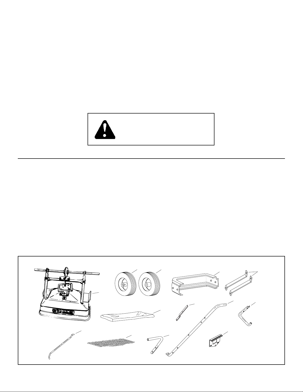
Your broadcast spreader carton contains parts as shown on pages 2 and 3. Identify all parts and lay out
as shown.
3. Wear eye and hand protection when handling and
when applying lawn or garden chemicals.
4. Read the chemical label instructions and cautions
for handling and applying the chemicals purchased
for spreading.
5. Keep all nuts, bolts and screws tight to be sure
equipment is in safe working condition.
6. Follow maintenance and lubrication instructions as
outlined in this manual.
CARTON CONTENTS
LOOSE PARTS IN CARTON
1. Hopper Assembly
2. Wheel, Drive
3. Wheel, Idler
4. Spreader Shield
5. Braces (2)
6. Flow Control Rod
7. Vinyl Hopper Cover
6
8. Hopper Screen
9. Handle Tube (short)
10. Flow Control Arm
11. Handle Tube (long)
12. Leg Stand Tube
13. Flow Control Mount Bracket
Hardware Package (not shown)
2
1
8
3
10
7
9
4
11
13
5
12
2
Page 3
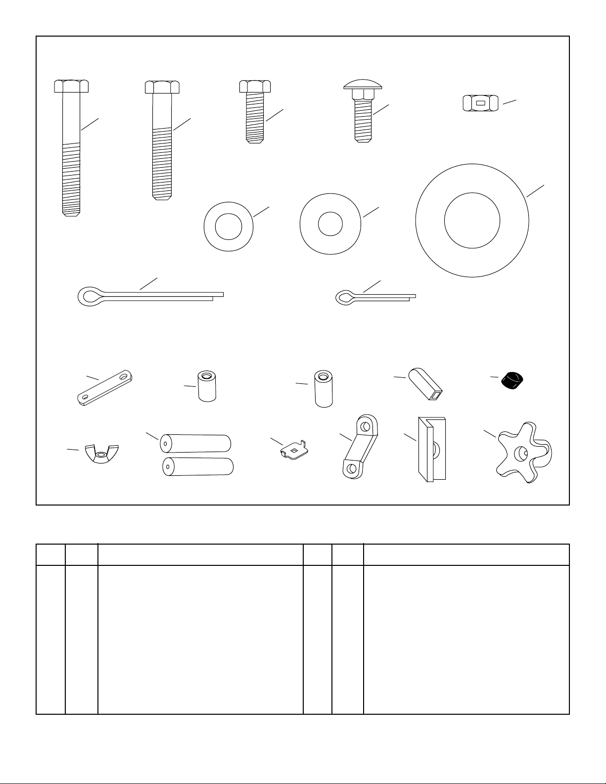
FULL SIZE
A B
K
C
F
I
D
G
J
E
H
NOT FULL SIZE
L
M
N
O
Q
P
HARDWARE PACKAGE
KEY QTY. DESCRIPTION
A 6 Hex Bolt, 1/4-20 x 1-3/4" Long
B 2 Hex Bolt, 1/4-20 x 1-1/2" Long
C 8 Hex Bolt, 1/4-20 x 3/4" Long
D 3 Carriage Bolt, 1/4-20 x 3/4" Long
E 16 Hex Lock Nut, 1/4-20 Thd.
F 20 Flat Washer, 5/16" SAE
G 8 Nylon Washer
H 4 Flat Washer, 1-5/8" x 25/32"
I 1 Cotter Pin, 1/8" x 1-1/2"
J 1 Cotter Pin, 3/32" x 3/4" Long
R
S T
KEY QTY. DESCRIPTION
K 1 Flow Control Link
L 1 Spacer Tube, Short
M 1 Spacer Tube, Long
N 1 Grip
O 1 Vinyl Cap
P 1 Nut, Plastic Wing 1/4"
Q 2 Handle Grip
R 1 Adjustable Stop
S 4 Swivel Bracket
T 2 Angle Stop Bracket
U 2 Plastic Knob
U
3
Page 4
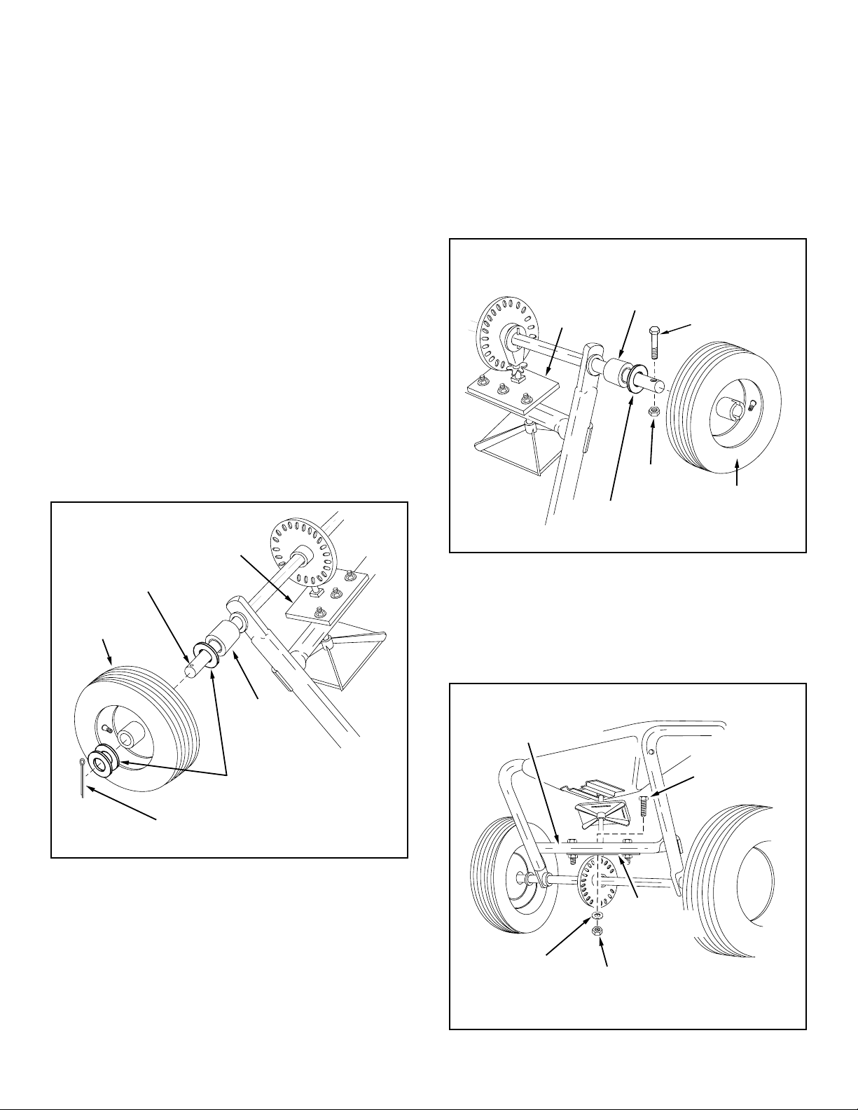
ASSEMBLY INSTRUCTIONS
CROSSOVER
TUBE
3/8" HEX
BOLT
3/8" HEX
LOCK NUT
3/8" FLAT
WASHER
SHAFT
SUPPORT
PLATE
5. Place the short spacer tube and a 3/4" washer
onto the end of the axle that has the large drilled
hole (left hand side). See Figure 2.
TOOLS REQUIRED FOR ASSEMBLY
(1) Pliers
(2) 7/16" Open or Boxed End Wrenches
(3) 9/16" Open or Boxed End Wrenches
1. Place the spreader upside down.
2. Assemble the long spacer tube and a 3/4" washer
onto the end of the axle that has the small drilled
hole (right hand side). See Figure 1.
3. Place the idler wheel (no notch in hub) onto the
axle. The air valve should face to the outside.
See Figure 1.
4. Assemble one or two more 3/4" washers onto the
axle and then assemble the 1/8" x 1-1/2" cotter
pin. See Figure 1.
SHAFT
SUPPORT
SMALL
HOLE
PLATE
6. Place the drive wheel onto the axle. The notched
hub and the air valve should face to the outside.
See Figure 2.
7. Fasten the wheel to the axle using a 1/4" x 1-3/4"
hex bolt and a 1/4" hex lock nut. See Figure 2.
SHORT
SHAFT
SUPPORT
PLATE
3/4" WASHER
FIGURE 2
SPACER
TUBE
1/4" HEX
LOCK NUT
1/4" x 1-3/4"
HEX BOLT
DRIVE
WHEEL
FIGURE 1
IDLER
WHEEL
3/4" WASHERS
1/8" x 1-1/2"
COTTER PIN
8. Remove the middle 3/8" hex bolt, flat washer and
hex lock nut from the crossover tube. See figure
3.
LONG
SPACER
TUBE
FIGURE 3
4
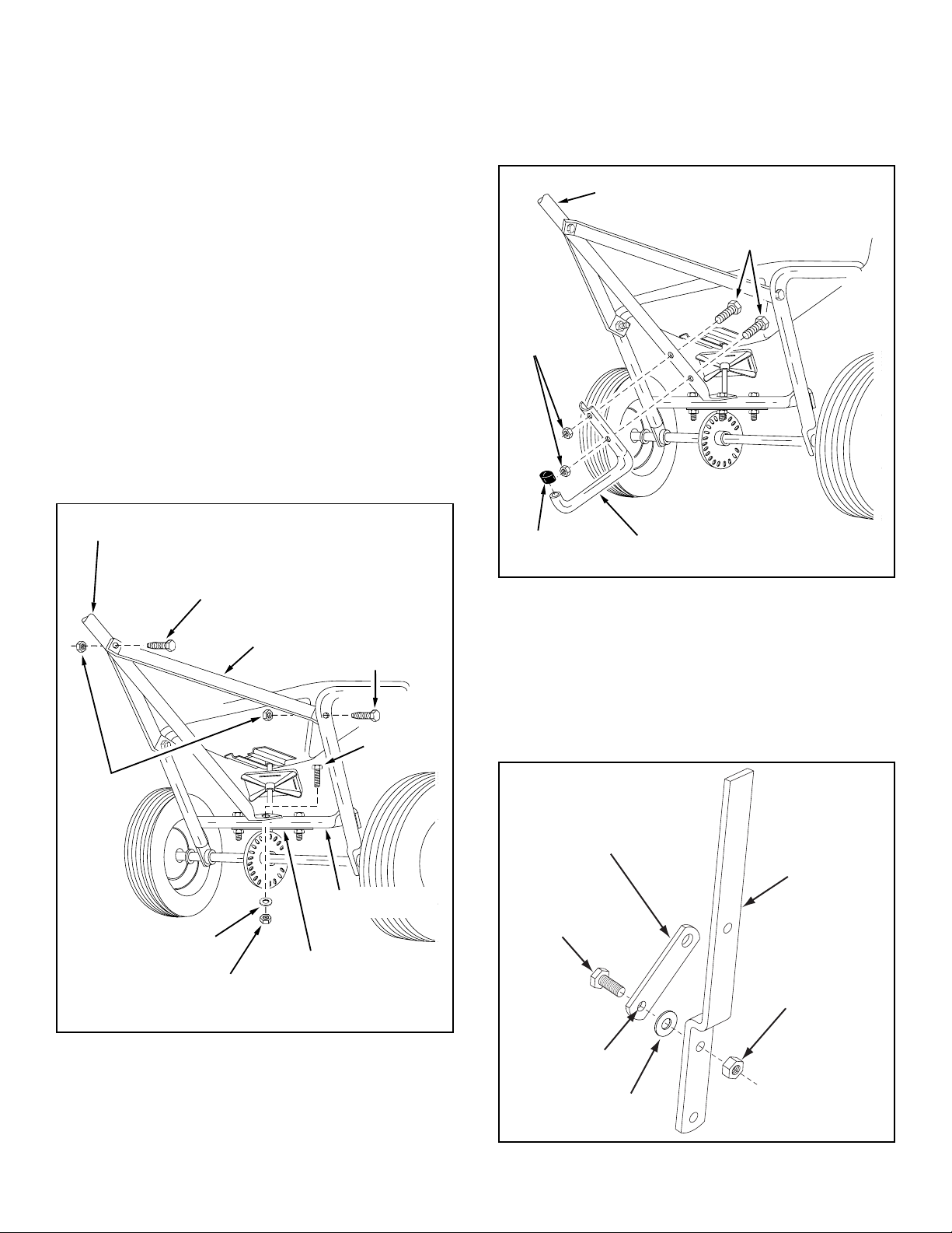
Page 5
FLOW CONTROL
LINK
FLOW
CONTROL
ARM
1/4" HEX
LOCK NUT
1/4" x 3/4"
HEX BOLT
SMALLEST
HOLE
NYLON
WASHER
IMPORTANT: Do Not assemble long handle tube on
HANDLE TUBE (LONG)
1/4" x 1-1/2"
HEX BOLTS
1/4"
LOCK
NUT
VINYL CAP
LEG STAND TUBE
same side of crossover tube as shaft support
plate. Assemble on opposite side.
9. Place the long handle tube onto the crossover tube
on the opposite side from the shaft support plate.
Fasten with 3/8" hex bolt, flat washer and hex lock
nut removed in the previous step. See figures 3
and 4. Do not tighten at this time.
10. Assemble two handle braces to the inside of the
hopper frame, one on each side, using two 1/4" x
1-3/4" hex bolts and two 1/4" lock nuts. See figure
4. Do not tighten at this time.
11. Assemble the other end of the two handle braces
to the long handle tube using a 1/4" x 1-3/4" hex
bolt and 1/4" lock nut. Do not tighten at this time.
See figure 4.
12. Tighten all hex lock nuts and bolts in the same
sequence as assembled in steps 9 through 11.
See figure 4.
13. Assemble the leg stand tube to the long handle
tube using two 1/4" x 1-1/2" hex bolts. Secure
tightly with two 1/4" hex lock nuts. See figure 5.
14. Place a vinyl cap onto the end of the leg stand
tube. See figure 5.
HANDLE TUBE (LONG)
1/4"
LOCK
NUT
FLAT WASHER
HEX BOLT
1/4" x 1-3/4"
3/8" HEX
LOCKNUT
HITCH
BRACE
CROSSOVER
TUBE
SHAFT
SUPPORT
PLATE
HEX BOLT
1/4" x 1-3/4"
3/8" HEX
BOLT
FIGURE 5
15. Assemble the flow control link (end with small
hole) to the flow control arm using a 1/4" x 3/4"
hex bolt, a nylon washer and a 1/4" hex lock nut
as shown in figure 6. Tighten carefully. The flow
control link should not be loose but should pivot
with no more than slight resistance.
FIGURE 4
FIGURE 6
5
Page 6

16. Assemble the flow control arm to the flow control
1/4" x 1-3/4"
HEX BOLT
1/4" HEX
LOCK NUT
HANDLE
TUBE
(SHORT)
HANDLE
TUBE
(LONG)
HANDLE GRIP
FLOW CONTROL
MOUNTING BRACKET
5/16"
FLAT
WASHERS
mounting bracket using a 1/4" x 3/4" hex bolt, two
nylon washers and a 1/4" hex lock nut as shown
in figure 7. Tighten carefully. The flow control
arm should be snug, but should pivot with no
more than a slight resistance.
17. Assemble the vinyl grip. See figure 7.
VYNIL GRIP
FLOW CONTROL
FLOW
CONTROL
ARM
MOUNTING
BRACKET
19. Hook free end of flow control rod through hole in
slide gate bracket located near bottom of hopper.
See figure 9.
SLIDE
GATE
HOPPER
BRACKET
FLOW
CONTROL
ROD
1/4" x 3/4"
HEX BOLT
1/4" HEX
LOCK NUT
(2) NYLON
WASHERS
FIGURE 7
18. Place a 5/16" flat washer onto the end of the flow
control rod. Insert the end of the rod through the
slot in the flow control mounting bracket and
through the hole in the flow control link. Secure
with a 3/32" x 3/4" cotter pin. See figure 8.
3/32"
COTTER
5/16" FLAT
WASHER
FLOW
CONTROL
ROD
FIGURE 9
20. Assemble both the flow control mounting bracket
and the short handle tube to the long handle tube
using two 1/4" x 1-3/4" hex bolts, four 5/16" flat
washers and two 1/4" hex lock nuts. Do not
tighten at this time. See figure 10.
21. Place a handle grip on each handle. See figure
10.
PIN
FIGURE 8
SLOT
FIGURE 10
FLOW
CONTROL
LINK
6
Page 7

22. Place the adjustable stop into the "ON" end of
the slot in the top of the flow control mounting
bracket. Secure with the 1/4" x 3/4" carriage bolt,
a nylon washer, a 5/16" flat washer and the nylon wing nut. See figure 11.
NYLON
WING NUT
5/16" FLAT
WASHER
NYLON
WASHER
ADJUSTABLE
STOP
23. Position the flow control mounting bracket
(Refer to figure 12).
a. Push on flow control arm until it locks in "OFF"
position.
b. Slide flow control mounting bracket along tube
until closure plate in bottom of hopper just
closes.
c. Snug the 1/4" lock nuts just enough to hold
flow control mounting bracket in place.
d. Set adjustable stop at "5". Pull flow control
arm against stop. Verify that closure plate has
opened about half way.
e. If closure plate does not open half way, it may
be closed too far at "OFF". Adjust position of
flow control mounting bracket until closure
plate will open about half way at "5" and still
close when arm is locked in "OFF". Tighten
1/4" lock nuts.
FIGURE 11
1/4" x 3/4"
CARRIAGE BOLT
FLOW
CONTROL
ARM
FIGURE 12
ON
ON
1
2
3
4
5
6
7
8
9
10
OFF
OFF
AJDUSTABLE
STOP
SETTING "5"
7
Page 8

24. Attach an angle stop bracket and a swivel bracket
to the rear hole in the R.H. shield bracket using
a 1/4" x 3/4" hex bolt, two 5/16" washers, a nylon washer and a 1/4" hex lock nut. Place the
angle stop bracket on the inside and the swivel
bracket on the outside. Tighten the locknut so
that the swivel bracket can pivot freely. See figure 13. Repeat step on L.H. shield bracket.
25. Attach a swivel bracket to the front hole in the
R.H. shield bracket using a 1/4" x 3/4" hex bolt,
two 5/16" washers, a nylon washer and a 1/4"
hex lock nut. Tighten the locknut so that the
swivel bracket can pivot freely. See figure 13.
Repeat step on L.H. shield bracket.
26. Assemble the spreader shield to the front swivel
brackets using two 1/4" x 3/4" carriage bolts, 5/16"
washers and the two 1/4" plastic knobs. See figure
14.
27. Assemble the spreader shield to the rear swivel
brackets using two 1/4" x 3/4" hex bolts, four 5/16"
washers and two 1/4" hex lock nuts. Tighten the
locknuts so that the swivel bracket can still pivot
freely. See figure 14.
5/16" WASHER
PLASTIC
KNOB
1/4" HEX
LOCK NUT
FIGURE 13
5/16"
WASHER
ANGLE STOP
BRACKET
NYLON
WASHER
SWIVEL
BRACKET
1/4" x 3/4"
HEX BOLT
NYLON
WASHER
SHIELD
BRACKET
1/4" LOCK NUT
1/4" x 3/4"
HEX BOLT
1/4" x 3/4"
CARRIAGE BOLT
FIGURE 14
28. Place the hopper screen down into the hopper
to help break up clumpy material and to prevent
large clumps from reaching the bottom of the
hopper and clogging the opening. See figure 15.
HOPPER SCREEN
FIGURE 15
8
SHI
Page 9

OPERATION
HOW TO USE YOUR SPREADER
SETTING THE FLOW CONTROL
(Refer to figure 12 on page 7.)
1. Refer to the application chart on page 8 and to
the instructions on the fertilizer bag to select the
proper flow rate setting.
2. Loosen the nylon wing nut, set the adjustable
stop to the desired flow rate setting and retighten
the wing nut. The higher the setting number, the
wider the opening in the bottom of the hopper.
3. Pull the flow control arm against the adjustable
stop for the on position and toward the hopper
for the off position.
SETTING THE SPREADER SHIELD
4. For a normal spread pattern used in open areas,
loosen the plastic knob on each side of the shield,
raise the shield and retighten the knobs.
7. Always shut the closure plate before turning or
stopping the spreader.
8. If fertilizer is accidentally deposited too heavily
in a small area, soak the area thoroughly with a
garden hose or sprinkler to prevent burning of
the lawn.
9. To insure uniform coverage, make each pass so
that the broadcast pattern slightly overlaps the
pattern from the previous pass as shown in figure 16. The approximate broadcast widths for
different materials are shown in the application
chart on this page.
10. When broadcasting weed control fertilizers, make
sure the broadcast pattern does not hit evergreen
trees, flowers or shrubs. Lower the spreader
shield to limit the dispersal pattern. Reduce the
flow control setting according to the application
chart on page 10.
11. Heavy moisture conditions may require a cover
over the hopper to keep contents dry. The vinyl
cover acts as a wind and moisture shield, but
should not be used as a rain cover.
5. For a restricted spread pattern when applying
material next to sensitive plants or in a confined
area, loosen the plastic knob on each side of the
shield, lower the shield and retighten the knobs.
USING YOUR SPREADER
We do not recommend the use of any powdered lawn
chemicals, due to difficulty in obtaining a satisfactory
or consistent broadcast pattern.
1. Determine approximate square footage of area
to be covered and estimate amount of material
required.
2. Before filling the hopper make sure the flow control arm is in the off position and the closure plate
is shut.
3. Set the adjustable stop with the flow control arm
still in the off position. Refer to the application
chart on this page and to the instructions on the
fertilizer bag to select the appropriate flow rate
setting.
4. Fill the hopper with up to 125 pounds of material, breaking up any lumps. The hopper screen
helps prevent any large lumps from clogging the
opening in the bottom of the hopper.
5. The application chart is calculated for light to
heavy application at a walking speed of 3 mph,
or 100 ft. in 23 seconds. A variation in speed will
require an adjustment of the flow rate to maintain the same coverage. The faster you walk, the
wider the broadcast width.
6. Always start the spreader in motion before
opening the closure plate.
SHIELD UP
8’ to
10’
OVERLAP
SHIELD DOWN
3’ to
4’
OVERLAP
FIGURE 16
9
Page 10

IMPORTANT: Application rates shown in the chart
are affected by humidity and by the moisture content of the material (granular and pellet). Some
minor setting adjustments may be necessary to
compensate for this condition.
APPLICATION CHART (SHIELD UP)
TYPE FLOW SETTING SPREAD
MATERIAL 3 MPH WIDTH
(100 FT. IN 23 SEC.) IN FEET
FERTILIZER
Powder 3 - 5 3 - 4
Granular 3 - 5 8 - 10
Pelleted 3 - 5 10 - 12
Organic 6 - 8 6 - 8
GRASS SEED
Fine 3 - 4 6 - 7
Coarse 4 - 5 8 - 9
ICE MELTER 6 - 8 10 - 12
MAINTENANCE
CHECK FOR LOOSE FASTENERS
1. Before each use make a thorough visual check of
the spreader for any bolts and nuts which may have
loosened. Retighten any loose bolts and nuts.
CHECK FOR WORN OF DAMAGED PARTS
2. Check for worn or damaged parts before each use.
Repair or replace parts if necessary.
CHECK TIRE INFLATION
3. Check if tires are adequately inflated before each
use. Do not inflate beyond maximum recommended
pressure.
CAUTION: DO NOT inflate tires beyond
the maximum recommended pressure
printed on side of tire.
APPLICATION CHART (SHIELD DOWN)
TYPE FLOW SETTING SPREAD
MATERIAL 3 MPH WIDTH
(100 FT. IN 17 SEC.) IN FEET
FERTILIZER
Powder 1 - 3 3 - 4
Granular 1 - 3 3 - 4
Pelleted 1 - 3 3 - 4
Organic 3 - 4 3 - 4
GRASS SEED
Fine 1 - 3 3 - 4
Coarse 2 - 3 3 - 4
ICE MELTER 2 - 4 3 - 4
OPERATING SPEED - 3 MPH. (100 ft. in 23 seconds)
CLEANING
4. Rinse inside of hopper and exterior of spreader and
dry off before storing.
LUBRICATE (See figure 17.)
5. Lightly apply automotive grease as needed to the
sprocket and gear.
6. Oil the nylon bushings on the vertical sprocket shaft
and on the axle at least once a year, or more often
as needed.
7. Oil right hand (idler) wheel bearing at least once a
year or more often as needed.
OIL
OIL
FIGURE 17
10
GREASE
Page 11

STORAGE
1. Rinse inside of hopper and exterior of spreader
and dry off before storing.
2. Store in a clean, dry area.
SERVICE AND ADJUSTMENTS
1. If the axle, slotted gear and sprocket assembly
is disassembled, mark down the positions of the
parts as they are removed. The drive wheel and
sprocket positions in relation to the slotted gear
determine which direction the spreader plate will
spin. Be sure to reassemble them in their original positions. (Refer to figure 2 on page 4.) Use
shim washers (Ref. no. 20 on pages 12 and 13)
as needed for minimum backlash. Add grease
to gear and sprocket.
2. If the agitator wire becomes damaged or worn it
can be replaced. Loosen the 3/8" hex nut on top
of the sprocket shaft until agitator wire is free.
Remove old agitator wire from hole in agitator
sleeve and replace with new agitator wire. Position agitator wire so that sprocket shaft turns
freely, then tighten 3/8" hex nut on top of sprocket
shaft. See figure 18.
AGITATOR
WIRE
FIGURE 18
SPROCKET
SHAFT
3/8" LOCKNUT
AGITATOR
SLEEVE
11
Page 12

REPAIR PARTS FOR BROADCAST SPREADER MODEL 45-02102-101
69
39
E
F
47
68
70
40
11
40
4
30
26
25
60
61
31
3
9
59
37
48
44
11
9
40
62
39
11
C
63
39
42
35
4
62
23
13
40
39
8
9
40
41
45
47
34
7
7
15
52
37
2
54
32
12
9
20
9
58
51
50
10
57
56
18
43
B
27
55
5
11
6
46
33
38
36
D
53
19
18
20
21
9
35
9
16
7
A
B
9
28
A
17
9
40
C
9
49
22
40
40
11
64
65
1
7
32
39
53
32
9
40
66
7
E
F
14
9
9
62
67
7
24
40
9
D
22
12
Page 13

REPAIR PARTS FOR BROADCAST SPREADER MODEL 45-02102-101
REF. PART QTY. DESCRIPTION
NO. NO.
1 44466 1 Hopper
2 43882 4 Rivet, Stainless
3 62482 1 Ass'y, Guide Closure
4 44462 1 Tube, Frame
5 23753 1 Slide Gate Angle Bracket
6 23758 1 Slide Gate Bracket
7 1509-69 12 Bolt, Hex 1/4-20 x 1-3/4" Lg.*
8 24857 1 Flow Control Link
9 43013 22 Nut, Hex Lock 1/4-20 Thd. *
10 43808 1 Tube, Crossover
11 43012 9 Bolt, Hex 1/4-20 x 3/4" Lg. Gr. 5
12 44566 1 Spring, Torsion
13 44463 1 Tube, Handle (Long)
14 44457 1 Wheel (Drive)
15 44456 1 Wheel (Idler)
16 44464 1 Tube, Handle (Short)
17 23752 1 Shaft, Axle
18 43851 2 Pin, Spring 5/32" Dia. x 1-1/4" Lg.
19 43871 1 Bushing, Axle Shaft
20 1540-32 5 Washer, Flat 1.25 x .78 x .01
21
1540-162
22 47615 2 Bearing, Flange
23 44494 1 Tube, Long Spacer 1.33" Lg.
24 44450 1 Tube, Short Spacer 1.00" Lg.
25 47437 1 Shaft, Sprocket
26 04367 1 Spreader Plate
27 43850 1 Pin, Spring 1/8" Dia. x 5/8" Lg.
28 44465 1 Tube, Leg Stand
29
C-9M5732
30 23766 1 Sleeve, Agitator
31 43878 1 Wire, Agitator
32 43088 13 Washer, Flat 1/4" Std.
33 44468 1 Sprocket - 6 Tooth
34 44514 1 Rod, Flow Control
35 23525 2 Brace, Hitch
36 23762 1 Support, Shaft
1 Washer, 2.0 x .81 x 10ga
2 Pop Rivet (Not Shown)
REF. PART QTY. DESCRIPTION
NO. NO.
37 44482 2 Grip, Handle
38 46055 1 Pin, Spring 1/8" Dia. x 1" Lg.
39 1543-069 14 Washer, Nylon
40
R19111116
41 24858 1 Stop, Adjustable
42 24855 1 Bracket, Flow Control Mount
43 62474 1 Gear Assembly
44 24856 1 Flow Control Arm
45 44101 1 Cotter Pin 3/32" x 3/4" Lg.*
46 23533 1 Plate, Closure
47 44950 3 Bolt, Carriage 1/4-20 x 3/4" Lg.
48 43848 1 Grip, Flow Control Arm
49 44481 1 Cap, Vinyl
50 41576 2 Bolt, Hex 3/8"-16 x 1-3/4" Lg.
51 43054 1 Bolt, Hex 3/8"-16 x 2" Lg.
52 47141 1 Nylon Wing Nut, 1/4-20
53 44285 2 Bushing, Delrin 3/8" I.D.
54 43015 1 Nut, Hex 3/8-16 Thd.*
55 43003 1 Lock Washer 3/8"
56 43082 3 Nut, Hex Lock 3/8-16 Thd.
57 43070 5 Washer, 3/8" Std.
58 43648 2 Bolt, Hex 1/4"-20 x 1-1/2" Lg.
59 43084 2 Bolt, Hex 5/16"-18 x 1-3/4" Lg.
60 43086 2 Washer, Lock 5/16"
61 43064 2 Nut, Hex Lock 5/16"
62 43009 4 Washer, 1-5/8" x 25/32"
63 43093 1 Cotter Pin, 1/8" x 1-1/2"
64 43962 1 Vinyl Hopper Cover
65 47441 1 Hopper Screen
66 24125 2 Shield Bracket
67 23999 2 Angle Stop Bracket
68 46119 1 Spreader Shield
69 23998 4 Shield Swivel Bracket
70 46120 2 Plastic Knob
48324 1 Owner's Manual
20 Washer, 5/16 SAE
*Purchase common hardware locally.
13
Page 14

NOTES
14
Page 15

NOTES
15
Page 16

 Loading...