

Page 1

PRINTED IN U.S.A.
FORM NO. 46082
(6/93)
Page 2
RULES FOR SAFE OPERATION
ASSEMBLY INSTRUCTIONS
Preventing accidents is the responsibility of every
equipment operator. The following general safety
precautions must be fully understood and followed
by every operator.
1. Do not at anytime carry passengers in this cart.
It is designed for carrying materials only and not
intended to carry passengers.
2. Be careful on any grade (hill) and stay off of
steep grades.
3. Use caution when loading cart to avoid tipping.
4. Avoid large holes and ditches when transporting
loads.
Your Farm/Yard Cart carton contains a hardware
package with parts as shown in the chart below and
figure 1.
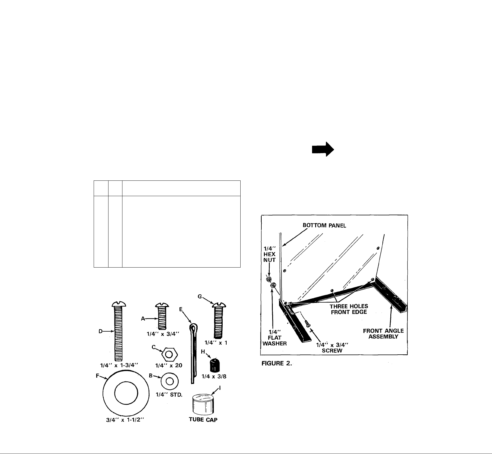
Contents of Hardware Pack: (See figure 1)
REF.
QTY.
NO.
A 13
B 25
C 25
D
E 2
F
G
H
1 4 Tube Cap 1" x 1" Lg.
Screws, 1/4-20 x 3/4" Long
Flat Washer 1/4" I.D.
Hex Nuts 1/4-20 Thread
8
Screws, 1/4-20 x 1-3/4" Long
Cotterpins
4
Flat Washers 25/32" I.D. x 1-1/2;;
O.D.
4
Screws 1/4-20 x 1" Long
6 Rubber Cap 1/4" x 3/8" Lg.
DESCRIPTION
TOOLS REQUIRED
(1) Screw Driver
(1) Pair of Pliers
(1) 7/16" Operi End or Box Wrench
When assembling your cart, place the heads of all
screws to the inside and hex nuts with flat washers
outside.
1. Lay the front angle assembly down (flat) on floor
and stand the bottom panel in position as
shown in figure 2.
NOTE
The bottom panel has one galvanized
edge, this is the rear. The front edge
has three holes. See figure 2.
HARDWARE REFERENCE CHART
FIGURE 1.
Line up three holes in bottom panel with holes
in front angle assembly. Start three 1/4" x 3/4"
truss head screws through bottom panel, then
through angle. Secure screws with flatwashers
and hex nuts. See figure 2. Tighten securely.
Page 3
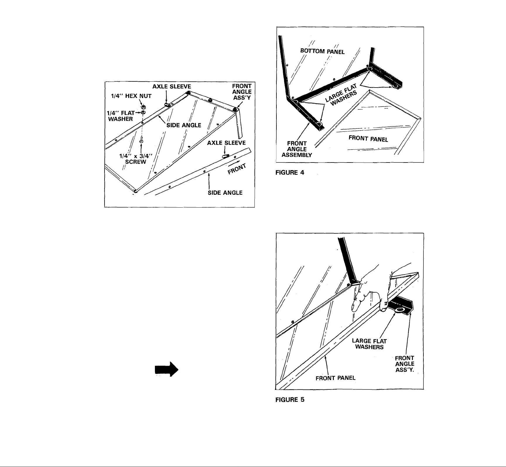
3. Turn front angle assembly and bottom panel
upside down as shown in figure 3.
4. Lay the two side angles on bottom panel so that
the axle sleeves are towards the front angle
assembly. See figure 3.
FIGURE 3
8. Lay the front panel on top of the four large
washers and in the front angle assembly. See
figure 5.
5. Secure the two side angle assemblies to the
bottom panel with six 1/4" x 3/4" truss head
screws, flatwashers and hex nuts. Only make
finger tight, until all six screws are in place, then
tighten securely. See figure 3.'
6. Stand cart on its front end with front angle
assembly on the floor. See figure 4.
7. Place four large 1-1/2" dia. flatwashers (used on
wheel axle) on the inside of front angle
assembly. See figure 4.
NOTE
These washers act as shims and are
just for assembly purposes. You will
remove them later.
Page 4

9. Place one side panel in position, against side
angle and down on top of front panel. Start one
1/4" X 3/4" truss head screw through the center
hole in side panel and side angle. Secure with
hex nut and flat washer. See figure 6. Make only
finger tight at this time.
FIGURE 7
FIGURE 6
10. Start one 1/4” x 1” truss head screw through
front hole on side panel and side angle. Start
another 1 /4” x 1” truss head screw through
top hole on side panel and front angle assembly,
next place support strap over these two screws,
secure with hex nuts and cover threads of top
screw with a rubber cap. See figure 6. Make
only finger tight at this time.
11. Repeat steps 9 and 10 for the other side panel.
12. Assemble one 1/4" x 3/4" truss head screw
through bottom hole in side panel and front
angle assembly. Secure flat washer and hex nut.
See figure 7. Make only finger tight at this time.
15. Lay cart down on floor, so that the sides are up
in a normal position. Remove the front panel,
by sliding it up, and remove the four large
washers you used for shims. See figure 8.
13. Repeat step 12 for the other side panel.
14. Place axle through axle sleeves as shown in
figure 11 page 5. Tighten all nuts and screws
securely.
FIGURE 8
Page 5

16. Place tube caps on leg tube and handle as
shown in figure 10. Stand cart up on its front
end again and assemble the leg tube as shown
in figure 9 using four 1/4” x 1-3/4” truss head
screws through side panels and leg tube Secure
with flat washers and hex nuts. See figure 9.
17. With the cart still standing on its front angle
assembly, assemble the handle tube.
FIGURE 10
19. Now lay the cart down, do that it is upside
down, to assemble the wheels. See figure 11
and 12.
18. Place the handle tube over the side panels and
line up the four holes. Assemble four 1/4” x
1-3/4” truss head screws through the side
panels and handle. Secure with flat washers,
hex nuts and cover threads with rubber caps.
See figure 10.
Page 6

20. Place one 1-1/2" dia. flat washer on axle,
then wheel, one more large flat washer and
secure with cotter pin. See figure 12 and note
below. Repeat step for other wheel.
NOTE
If cotter pin can not be
assembled through hole in the
axle ends, remove one washer
from inside, next to sleeve.
AXLE
MAINTENANCE
1. Grease or oil wheel bearings occasionally. Use
automotive wheel bearing type grease or 20
weight oil.
2. Periodically retighten all screws, especially after
heavy use. Do not exceed load capacity rating
of 300 lbs.
3. Clean cart thoroughly after each use.
4. Store indoors during severe weather.
5. Apply light coat of varnish to all wood surfaces
annually.
6. Use glossy black enamel spray paint to touch-up
scratched or worn paint surfaces.
AXLE
SLEEVE
COTTER PIN-
(1) LARGE 1-1/2"
DIA. FLAT WASHER''
WHEEL
(OUTSIDE)
FIGURE 12
21. Turn cart right side up, so that it rests on its
wheels.
1-1/2" DIA.
LAT WASHER
(INSIDE)
WHEEL
22. Place front panel in guides to complete
assembly.
23. Your cart is now ready to use.
Page 7

MODEL 45-01761 7 CU. FT. FARM/YARD CART
PARTS LIST FOR MODEL NO. 45.01761 FARM/YARD CART
REF.
PART NO.
NO.
1
2
3 44014
4
5
6
7
8
9
10
44012 1 Front Panel 13 43949 4
44013 2 Side Panel
62527
62528
62529
44018
44019
23606
44975
QTY. DESCRIPTION
1 Bottom Panel
1
1
1
1
Side Angle Assembly-LH.
Side Angle Assembly-R.H. 15
Front Angle
Handle Tube
1 Leg Tube
2 Support Strap
Wheel Assembly Complete
2
w/bearings (20”)
11
44021
12
43010 2 Cotter Pin 1/8” X 1-1/4”
4 Tube Caps
Lg*
Purchase Common Hardware Locally.
REF.
NO.
PART NO
14 44022 8
44023
16 43088
17
18
43178 25
23991 1
19 44016
20
44259 4
21 44538 6
46082 1
QTY.
13
25
4
DESCRiniON
Flat Washers 25/32” I.D. x
1-1/2” O.D. X 3/32” Tk.
Truss Head Screws 1/4-20 x
1-3/4” Lg.*
Truss Head Screws 1/4-20
X 3/4” Lg.*
Flat Washer 1/4” I.D.*
Hex Nut 1/4-20 Thd.*
Axle
Bearing, Ball 3/4” I.D.
Truss Head Screws 1/4-20
X 1” Lg.*
Rubber Cap 1/4 x 3/8” Lg.
Owner's Manual
Page 8

%
REPAIR PARTS
303 West Raymond Street
Sullivan, Illinois 61951
(217) 728-8388
 Loading...