

Page 1
OWNERS
MANUAL
Model No.
45-01001
IMPORTANT:
Read Rules for
Safe Operation
and Instructions
PRINTED IN U.S.A.
UTILITY CART
Carefully
• 303 WEST RAYMOND • SULLIVAN, ILLINOIS 61951
• Assembly
• Operation
• Maintenance
• Repair Parts
FORM NO. 45154 (9/92)
Page 2

RULES FOR SAFE OPERATION
Preventing accidents is the responsibility of every
equipment operator. The following general safety
precautions must be fully understood and followed
by every operator.
1. Do not at anytime carry passsengers in this cart.
It is designed for carrying materials only and.not
intended to carry passengers.
3. When towing cart do not drive too close to a
creek or ditch and be alert for holes and othe>'
hazards. The above could cause you to loi
control of the cart and tractor.
4. Be careful on any grade (hill) and stay off of
steep grades.
5. Maximum towing speed - 10 M. P. H.
2. Do not tow this utility cart on a public
thoroughfare at any time. The operator is risk
ing injury from passing vehicles. Most local
ordinances prohibit operating a cart and
tractor such as this on a public thoroughfare.
Your utility cart carton and inner pack parts bag
contain parts as shown in the figure below. The hard
ware package contains parts shown in figure 1 on
page 3. Identify all parts and layout as shown in
figure below and figure 1.
CARTON CONTENTS
LOOSE PARTS IN CARTON
1. Cart Body (2)
2. Tailgate
3. Front Panel
4. Draw Bar Tongue
5. Wheel Support
LOOK FOR THIS SYMBOL TO POINT OUT
IMPORTANT SAFETY PRECAUTIONS. IT
A
6. Wheels (2)
7. Axle
8. Tailgate Reinforcement Bracket
9. Latch Stand Bracket
PARTS IN INNER PACK BAG
10. Tailgate Guides (2)
11. Corner Caps (2)
12. Hitch Bracket
13. Latch Lock
14. Latch Mount Bracket (2)
15. Hardware Package (not shown)
MEANS — ATTENTION. BECOME ALERT,
YOUR SAFETY IS INVOLVED.
Page 3
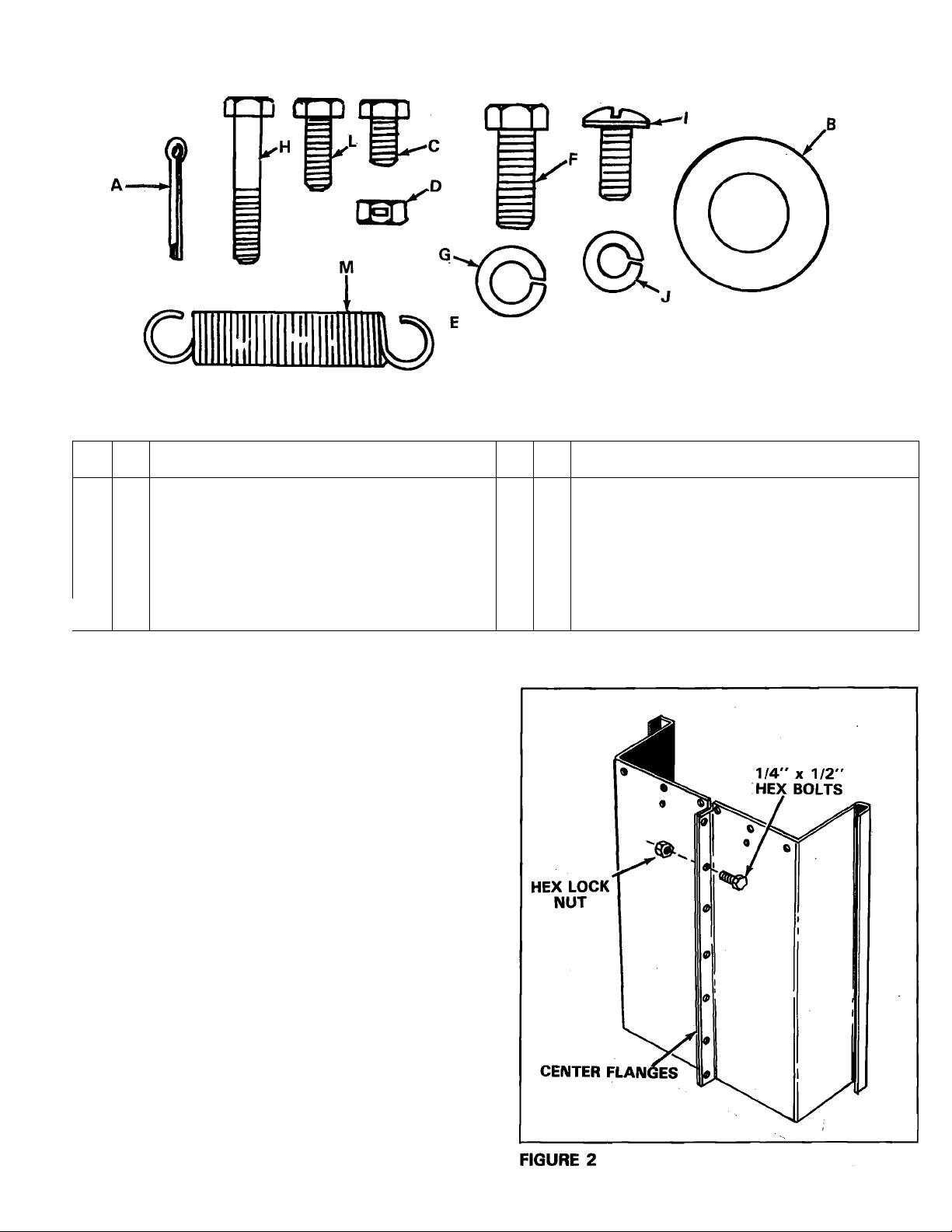
FIGURE 1 (FULL SIZE HARDWARE CHART)
KEY QTY
A 2
B 4
C 34
D 37
E
2
F
2
)G
2 Lock Washer 3/8"
Cotter Pin 1/8" X 1-1/4" Long
Washer 1.59 OD x .78 ID 1 14 Slotted Truss Hd Bolt 5/16-18 x 3/4"
Hex Head Bolt 1/4-20 x 1/2" Long
Hex Lock Nut 1/4-20 Thread
Hex Nut 3/8-16 Thread K
Hex Head Bolt 3/8-16 x 1" Long L
DESCRIPTION
ASSEMBLY INSTRUCTIONS
TOOLS REQUIRED FOR ASSEMBLY
(1) Screwdriver
(1) Pliers
(2) 7/16" Open End or Box Wrenches
(2) 1/2" Open End or Box Wrenches
(2) 9/16" Open End or Box Wrenches
KEY QTY
2
H
14
J
14 Hex Nut 5/16-18 Thread
M 1 Extension Spring
Hex Head Bolt 1/4-20 x 1-1/2" Long
Long
Lock Washer 5/16"
1 Hex Head Bolt 1/4-20 x 3/4" Long
DESCRIPTION
Remove the hardware pack and all loose parts
from the carton. Be sure carton is empty before
discarding.
Position cart body halves upright as shown
in figure 2.
Page 4
Start 1/4" X 1/2" hex bolts and 1/4" hex lock
nuts through flanges, only nnake finger tight
until all six (6) bolts are in place. See figure 2.
Tighten all six (6) bolts.
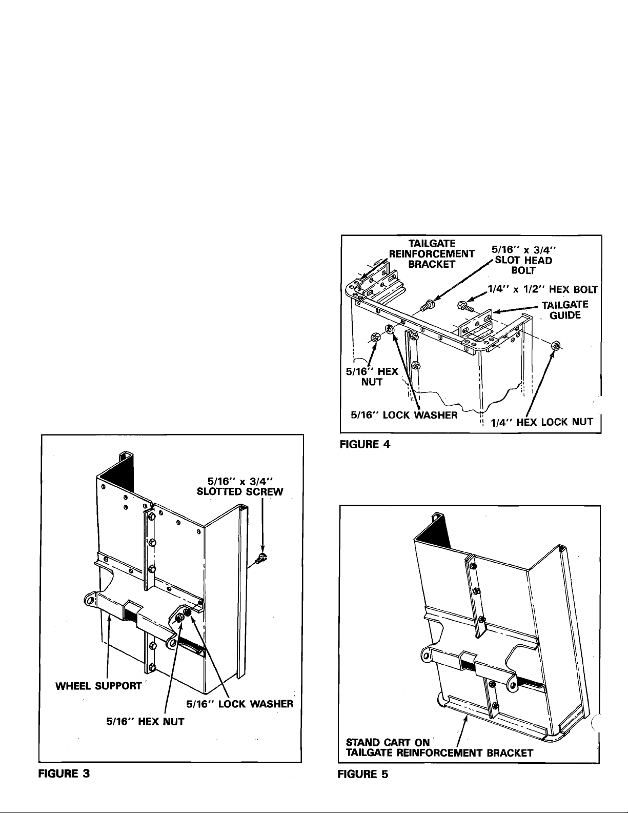
4. Position the wheel support in place on the
bottom of cart. See figure 3.
5. Assemble wheel support to cart with eight
5/16" X 3/4" slotted head screws, 5/16" lock
washers and 5/16" hex nuts. See figure 3.
Heads of screws go to the inside of cart and
should be tightened at this time.
6. Position the tailgate reinforcement bracket
over end of cart. See figure 5.
7. Start 5/16" X 3/4" slotted screws through
bottom of cart (heads of screws to the insic
of cart) and reinforcement bracket. Secure finger
tight with 5/16" hex nuts and 5/16" lock
washers. See figure 4.
8. Position the tailgate guides so that the holes
line up with reinforcement bracket and cart
body. Refer to tailgate guide detail in figure 4.
9. Secure tailgate guides with six 1/4" x 1/2" hex
bolts and 1/4" hex lock nuts. See figure 4.
Tighten bolts assembled in steps 6, 7, and 8 at
this time. Do not tighten others.
10. Reverse the cart position and stand up on
tailgate reinforcement bracket and proceed with
assembly steps 11 through 18. See figure 5.
Page 5

11. Assemble front panel to open end of cart body,
using 1/4” X 1/2” hex bolts and 1/4” hex lock
nuts. Bolt heads to inside of cart. Leave out (2)
bolts for latch stand bracket. See figure 6.
13. Assemble two front top corner caps and two
bolts in top flanges through tailgate reinforce
ment bracket using 1/4” x 1/2” hex bolts and
1/4” hex lock nuts. See figure 8. Tighten all
bolts.
14. Tighten all bolts assembled in steps 4 through
13, lower cart assembly to rest on top flanges,
with axle support up. See figure 12 on page 6.
12. Assemble latch stand bracket using four 1/4”
X 1/2” hex bolts and 1/4” hex lock nuts. See
figure 7.
15. Assemble two latch mount brackets, latch lock
and extension spring using one 1/4” x 3/4” hex
bolt and 1/4” hex lock nut. See figure 9. Do not
tighen 1/4” lock nut, latch lock must pivot
freely.
LATCH MOUNT BRACKETS
1/4” HEX
LOCK NUT
1/4" x 3/4”
HEX BOLT
EXTENSION
SPRING
LATCH LOCK
FIGURE 9
Page 6

16. Assemble latch lock subassembly to drawbar
tongue using 1/4" x 1/2" long hex bolt and 1/4"
hex lock nuts. See figure 10.
18. Assemble axle and draw bar tongue to wheel
support keeping open side of tongue facing up,
make sure that latch lock snaps over latch stand.
Secure axle to wheel support or axle brackets,
using 1/4" X 1-1/2" long hex bolts and 1/4" hex
lock nuts. See figure 12.
17. Assemble hitch bracket to drawbar tongue using
3/8" X 1" long hex bolts, 3/8" lock washers
and 3/8" hex nuts. See figure 11.
NOTE
Position valve stem to outside when
installing wheels on axle. See figure
13.
AXLE
COTTER PIN
WHEEL
1.59 OD
FLAT WASHER
VALVE STEM:
(outside)
FIGURE 11 FIGURE 13
6
1.59 OD
FLAT WASHER
Page 7

19. Assemble wheels as described in step 19,
using flat washers and cotter pins. See figure
13.
¿id. Turn cart assembly over to rest on wheels. This
completes the cart assembly. Be sure to read
safety rules and operating instructions before
using your new utility cart.
GENERAL SAFETY
PRECAUTIONS
Preventing accidents is the responsibility of every
equipment operator. The following general safety
precautions must be fully understood and followed
by every operator.
1. Do not at anytime carry passengers in this cart.
It is designed for carrying materials only and not
intended to carry passsengers.
2. Do not tow this utility cart on a public
thoroughfare at any time. The operator is risk
ing injury from passing vehicles. Most local
ordinances prohibit operating a cart and trac
tor such as this on a public thoroughfare.
3. When towing cart do not drive too close to a
creek or ditch and be alert for holes and other
hazards. The above could cause you to lose con
trol of the cart and tractor.
4. Be careful on any grade (hill) and stay off of
steep grades.
5. Maximum towing speed - 10 M.P.H.
NOTE
Weighs limit-See specifications for
each model. One cubic foot of dirt
weighs approximately 150 lbs.
Do Not exceed cart weight capacity
of 650 lbs.
OPERATION
To dump material from the trailer box, remove the
tailgate by lifting it straight up and out from between
the guides. Release the spring latch by pulling the
latch handle forward, away from the trailer box.
To avoid possible injury, be sure that
dk
no one is near the trailer before releas
ing latch.
A rope may be attached to the spring latch handle
for easy release by the operator while on the tractor
seat. The trailer box will tilt backward to empty its
contents. After unloading, pull the front of the box
down toward the trailer tongue until the latch snaps
in place. Replace tailgate if desired.
For best handling, do not load trailer
too heavily behind center of axle.
MAINTENANCE
At the beginning of each season, lubricate the latch,
latch pivot bolt, and the axle where the hitch tongue
pivots, with a light machine oil.
1. Grease or oil wheel bearings occasionally. Use
automotive wheel bearing type grease or 20
weight oil.
2. Recommended tire pressure is 12-14 Lbs.
CAUTION
NOTE
Page 8

REPAIR PARTS FOR: UTILITY CART MODEL No. 45-01001
8
Page 9

PARTS LIST FOR UTILITY CART MODEL 45-01001
REF.
NO.
PART NO. QTY.
1 23912 2 Cart Body
2
23470
3 23502
4 62458
5 23767
6
62020
7 23492
8
9
23506
23297
10 43000
11
23014
12 23913
13 23026
14 23484
15
43015
16 43008
17
18
43010
43009
19 43003
20 43175
21 43001
22 43012
23
24
43648
43083
25 43013
26
43814 14 Slotted Truss Head Bolt 5/16-18 x 3/4”
2 Latch Mount Bracket
1
Tailgate
1 Tailgate Reinforcement Bracket
2
Tailgate Guide
1
Latch Lock
1
Front Panel
1
Wheel Support
1
Latch Stand Bracket
1
Extension Spring
1
Hitch Bracket
1 Draw Bar Tongue
1
Axle 3/4” Diameter
2
Front Corner Cap
2
Hex Nut 3/8-16 Thread
2
Wheel, 4.30 x 3.75
2
Cotter Pin, 1/8” X 1-1/4” Long
4 Washer, 1.59 OD x .78 ID
2
Lock Washer 3/8”
34 Hex Head Bolt 1/4-20 x 1/2” Long
2 Hex Head Bolt 3/8-16 x 1” Long
1 Hex Head Bolt 1/4-20 x 3/4” Long
2
Hex Head Bolt 1/4-20 x 1-1/2” Long
14 Hex Nut 5/15-18 Thread
37 Hex Lock Nut 1/4-20 Thread
Long
27 43086
45154
14
Lock Washer 5/16”
1
Owners Manual
DESCRIPTION
Page 10

Page 11

Page 12

REPAIR PARTS
303 West Raymond Street
Sullivan, Illinois 61951
(217) 728-8388
 Loading...