

Page 1
owners
manual
Model No.
45-02171
190-521-000
IMPORTANT:
Read Rules for
Safe Operation
and Instructions
Carefully
Anri-l^l
PRINTED IN U.S.A
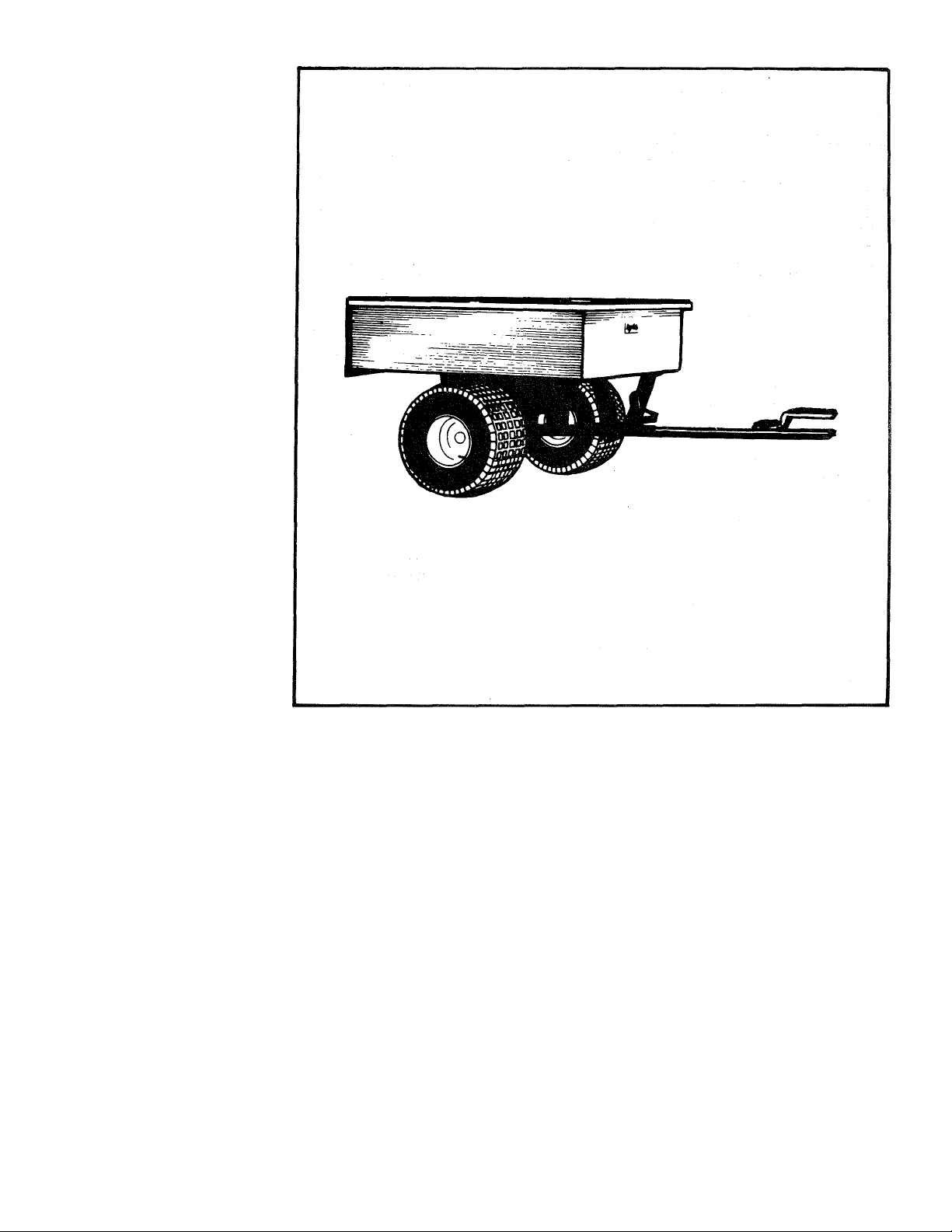
UTILITY CART
17 CU. FT. (SUPER 17)
• Assembly
• Operating
•Maintenance
•Repair Parts
303 WEST RAYMOND • SULLIVAN, ILLINOIS 61951
FORM NO. 46085
(Rev. 11/94)
Page 2
ASSEMBLY INSTRUCTIONS
Contents of Hardware Pack
(See figure 1)
IDENTIDICATION OF LOOSE PARTS
(See figure 2)
REF. QTY.
A 2
B 2
2
C
D 4
E 2
F 23
G 6
H
6
I 2
J 2
K
37
L 37
M
8
N
8
0 14
P 14
Q 14
R 2
DESCRIPTION
Tube Spacer 1-1/4" O.D. x 2" Lg.
Pin, Cotter 1/8 X 1-1/2" Long
Hex Nut 3/8 Thread
Washer, Flat 1.032 I.D.
Hub Cap
Hex Bolt 1/4 X 1/2" Long
Hex Bolt 1/4 X 5/8" Long
Hex Bolt 1/4- 3/4" Long
Lock Washer 3/8" I.D.
Hex Bolt 1/4 X 1-3/4" Long
Lock Washer 1/4" I.D.
Hex Nut 1/4" Thread
Hex Bolt 5/16 X 3/4" Long
Lock Nut 5/16" Thread
Slotted Truss Head Bolt 5/16" x 3/4"
Long
Lock Washer 5/16" I.D.
Hex Nut 5/16" Thread
Hex Bolt 3/8" X 1" Long
FIGURE 2
NOTE
Wheels (Al) are packed in a separate
carton).
LOOSE PARTS (See figure 2)
V Tailgate
W Cart Body (2)
X Tailgate Guides
Y Corner Caps
Z Front Panel
AA Draw Bar Tongue
AB Wheel Support
AC Wheel Axle Brackets
AD Axle
AE Tailgate Reinforcement Bracket
AF Latch Stand Bracket
AG Latch Lock Sub-Assembly
AH Hitch Bracket
Al Wheels
Page 3
1. Remove the hardware pack and all loose parts
from the carton. Be sure carton is empty before
discarding.
2. Layout all the parts as shown in figure 2.
3. Position the cart body halves (W) upright, on a
smooth level surface, as shown in figure 3.
A
CAUTION
To help prevent tipping of cart, assemble on a
smooth level surface such as a garage floor or a
paved driveway. Pay close attention to stability of the
cart body when it is in an upright position. DO NOT
LEAVE THE CART UNATTENDED IN UPRIGHT
POSITION. The cart could be knocked over causing
personal injury or damage to the cart.
4. Assemble the bolts (F), the lock washers (K) and
hex nuts (L) to the holes in center flanges. Do not
tighten till step 15, page 5. See figure 3.
5. Position the wheel support (AB) in place on the
bottom of the cart. See figure 4.
6. Assemble wheel support to cart with eight slotted
head screws (O) lock washers (P) and hex nuts
(Q). The heads of the screws should go to the
inside of the cart bed as shown in figure 4. These
screws should be tightened after they are all
assembled.
POSITION CART BODY HALVES
WITH LARGER DIAMETER HOLES AT TOP
FIGURE 3
FIGURE 4
Page 4
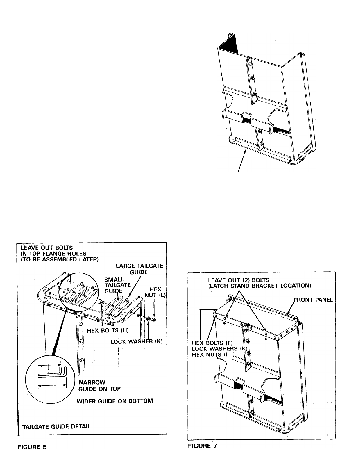
7. Position the tailgate reinforcement bracket (AE)
over end of cart. See figure 5.
8. Start slotted screws (0) through bottom of cart
(heads of screws to the inside of cart) and rein
forcement bracket. Secure finger tight with hex
nuts (Q) and lock washers (P). See figure 5.
9. Position the tailgate guides (X) so that the holes
line up with reinforcement bracket and cart
body. Refer to tailgate guide detail in figure 5.
10. Secure tailgate guides with six hex bolts (H) lock
washers (K) and hex nuts (L). See figure 5.
Tighten bolts assembled in steps 7, 8 and 9 at
this time. Do not tighten others.
STAND CART ON
TAILGATE REINFORCEMENT BRACKET
FIGURE 6
11. Reverse the cart position and stand on tailgate
reinforcement bracket and proceed with
assembly steps 12 through 20. See figure 6.
12. Assemble front panel to open end of cart body,
using 1/4" x 1/2" hex bolts (F), lock washers
(K) and hex nuts (L). Bolt heads to inside of cart.
Leave out (2) bolts for latch stand bracket. See
figure 7.
Page 5

13. Assemble latch stand bracket using four 1/4"
X 5/8" hex bolts (G), lock washers (K) and hex
nuts (L). See figure 8.
16. Assemble wheel axle brackets (2) to wheel
support, using 5/16" x 3/4" hex bolts (M) and
lock nuts (N). NOTE: Place welded tubes to
middle, as shown in figure 10.
14. Assemble two front top corner caps and two
bolts in top flanges through tailgate reinforce
ment bracket using 1/4" x 1/2" hex bolts (F),
lock washers (K) and hex nuts (L). See figure
9.
15. Tighten all bolts assembled in step 4 through
14, lower cart assembly to rest on top flanges,
with axle support up. See figures 10 and 13.
17. Assemble latch lock subassembly to drawbar
tongue using 1/4" x 5/8" long hex bolt (G), lock
washers (K) and hex nuts (L). See figure 11.
Page 6

18. Assemble hitch bracket to drawbar tongue,
using 3/8" X 1" long hex bolts (R), lock washers
(1) and hex nuts (C). See figure 12.
20. Assemble large diameter flat washer (D), wheel,
another flat washer (D), cotter key (B) and hub
cap (E) to each axle end.
NOTE
Position valve stem to outside when
installing wheels on axle. See figure
14.
AXLE
COTTER KEY (B)
WHEEL
19. Assemble axle, (2) tube spacers and draw bar
tongue to wheel support keeping open side of
tongue facing up, make sure that latch lock
snaps over latch stand. Secure axle to wheel
support or axle brackets, using 1/4" x 1-3/4"
long hex bolts (J), lock washers (K)) and hex
nuts (L). See figure 13.
FLAT WASHER (D)
VALVE STEM
(outside)
FLAT WASHER (D)
HUB CAP (E)
FIGURE 14
FIGURE 13
21, Turn cart assembly over to rest on wheels. This
completes the cart assembly. Be sure to read
safety rules and operating instructions before
using your new utility cart.
Page 7

GENERAL SAFETY PRECAUTIONS
Preventing accidents is the responsibility of every
equipment operator. The following general safety
precautions must be fully understood and followed
by every operator.
1. Do not at anytime carry passengers in this cart.
It is designed for carrying materials only and not
intended to carry passengers.
2. Do not tow this utility cart on a public
thoroughfare at any time. The operator is risk
ing injury from passing vehicles. Most local
ordinances prohibit operating a cart and
tractor such as this on a public thoroughfare.
3. When towing cart do not drive too close to a
creek or ditch and be alert for holes and other
hazards. The above could cause you to lose
control of the cart and tractor.
4. Be careful on any grade (hill) and stay off of
steep grades.
5. Maximum towing speed - 10 M.P.H.
OPERATION
To dump rr erial from the trailer box, remove the
tailgate by lifting it straight up and out from between
the guides. Release the spring latch by pulling the
latch handle forward, away from the trailer box.
NOTE
Weight limit-One cubic foot of dirt weights
approximately 150 lbs.
Do Not exceed cart weight capacity.
SPECIFICATIONS; MODEL 45-0217 -
17.0 Cu. Ft.
(Super 17)
Bed:
16 Ga. Steel Construction
36-1/2" W; 61" L; 14" H;
Approx. Inside Dim. —34" x
58-1/2"
Tailgate: Removable with Reinforced
Guides
Tires: 20.0" x 10.0" Pneumatic, Turf
Tread
Axle: 1.0" Dia. Steel
Capacity: Up to 1700 Lbs. Max.
Finish: Baked Enamel —Body; Ivory;
Black
Approx. Sh. Wt.: 195 Lbs.
Carton Size: 16-1/2" Hx20-1/2" W x 60-1/2"
(11.55 Cu. Ft.)
Carton Size: 20-1/2" H x 20-1/2" W x
20-1/2" L (4.99 Cu. Ft.)
CAUTION
▲
To avoid possible injury, be sure that
no one is near the trailer before
releasing latch.
A cord may be attached to the spring latch handle
for easy release by the operator while in the tractor's
seat. The trailer box will tilt backward to empty its
contents. After unloading, pull the front of the box
down toward the trailer tongue until the latch snaps
in place. Replace tailgate if desired.
NOTE
For best handling, do not load trailer
too heavily behind center of axle.
MAINTENANCE
At the beginning of each season, lubricate the latch,
latch pivot bolt, and the axle where the hitch tongue
pivots, with a light machine oil.
1. Grease or oil wheel bearings occasionally. Use
automotive wheel bearing type grease or 20
weight oil.
2. Recommended tire pressure is 12-14 Lbs.
Page 8

•Ту
'^Oû,
Ч
Л/Q
■ <S.
^^7?:
Г9
8
Page 9

PARTS LIST FOR UTILITY CART MODEL NO. 45-02171
REF.
NO.
1 23984
3
4 62457
5
6 23548
7 23490
8 23821
9 23363
10 62455
11
12 23989
13
14 23484
15 62359
16 43649
17 43093
18
19 43014
20 43175
21
22 43012
23
24 43177 39
25 43178
26 43182
27 43064 8
28
29 43086
30 43083
31
32 43003
33 43015
34 44678
PART NO. QTY.
23504 1
23549
23014 1
23820
43601
43866
1 509-69
43814
43001
46085
25
39
14
14
14
2
Cart Body
Tailgate
1
Sub-Ass'y - Rear Angie
Guide, Tailgate — Inside
2
Guide, Tailgate — Outside
2
Front Panel
1
Wheel Support
1
Latch Stand Bracket
1
Ass'y. Latch Lock
1
Hitch Bracket
1
Draw Bar Tongue
Wheel Axle 1'' Dia.
1
Cap, Front Corner
2
Wheel Axle Bracket
2
Wheel, 20 x 10-8
2
Cotter Pin 1/8” Dia. x 1-1/2” Lg.
2
Washer, Flat 1.032” I.D.
4
Hub Cap
2
Hex Bolt 1/4” X 1/2” Lg.
Hex Bolt 1/4” X 5/8” Lg.
6
Hex Bolt 1/4” X 3/4” Lg.
6
Hex Bolt 1/4” X 1-3/4” Lg.
2
Lock Washer 1/4” I.D.
Hex Nut 1/4” Thread
Hex Bolt 5/6-3/4” Lg.
8
Lock Nut 5/6” Thread
Slotted Truss Head Bolt 5/16” x 3/4” Lg.
Lock Washer 5/16” I.D.
Hex Nut 5/16” Thread
Lock Washer 3/8” x 1” I.D.
2
Lock Washer 3/8” I.D.
2
Hex Nut 3/8” Thread
2
Tube Spacer
2
Owner's Manual
1
DESCRIPTION
Page 10

Page 11

Page 12

REPAIR PARTS
303 West Raymond Street
Sullivan, Illinois 61951
(217) 728-8388
 Loading...