

Page 1

agria hispania, s.l.
Carretillas Elevadoras
Forklifts • Chariots Elevateurs
Modelos: TH-250
TH-300
TH-350
MANUAL DE INSTRUCCIONES Y MANTENIMIENTO
INSTRUCTIONS AND MAINTENANCE MANUAL
MANUEL D’INSTRUCTIONS ET D’ENTRETIEN
1
Page 2

agria hispania, s.l.
2
Page 3

agria hispania, s.l.
CARRETILLAS ELEVADORAS
FORK LIFTS
CHARIOTS ELEVATEURS
Válido para modelos
Been worth for models
Valu pour modèles
TH-250 • TH-300 • TH-350
MANUAL DE INSTRUCCIONES Y MANTENIMIENTO
INSTRUCTIONS ANO MAINTENANCE MANUAL
MANUEL D’ INSTRUCTIONS ET D’ ENTRETIEN
Antes de operar con la máquina,leer las indicaciones de este libro
y tener en cuenta las instrucciones de Funcionamiento y seguridad.
Before operating the machine,read this manual and follow the operating
and safety instructions contained in it.
Avant d’opérer avec la machine,lire les indications de ce livre et tenir en
compte les instructions de Fonctionnement et de Sécurité.
3
Page 4
agria hispania, s.l.
INTRODUCCIÓN
En este manual se indican las características e informaciones
necesarias para el conocimiento, el mantenimiento y el correcto
uso de la carretilla.
De la utilización racional,de las posibilidades de la carretilla y la
buena conservación de sus órganos, depende esencialmente,el
funcionamiento regular,la economía y la duración.
El no respetar estas normas así como el uso indebido de la carretilla puede ser causa de anulación de la garantía, con la que
AGRIA HISPANIA S.L. ampara a todos sus fabricados.
Se aconseja leer con atención las instrucciones contenidas en
este manual,para obtener de la carretilla los mejores resultados
y evitar accidentes.Si a pesar de ello le quedan dudas consulte
con AGRIA HISPANIA S.L. ó con el
distribuidor de su zona.
IMPORTANTE
LOS ACCIDENTES SON CAUSADOS CASISIEMPRE POR
NO CUMPLIR LAS MAS ELEMENTALES NORMAS DE
PRECAUCION Y SEGURIDAD. PREVEER LOS POSIBLES
RIESGOS Y ACTUAR ENCONSECUENCIA.CONLA DEBIDA
PRUDENCIA Y SIN DUDAS,ES LA MEJOR GARANTIA PARA
EVITAR ACCIDENTES.
ANTES DE PONER EN MARCHA LA CARRETIUA HAY QUE
LEER ATENTAMENTE LAS INSTRUCCIONES DE ESTE
MANUAL.
LOS PARRAFOS CON EL SIGNO:
IMPORTANTE
SON OPERACIONES QUE DEBEN REALIZARSE CON
ESPECIAL PRUDENCIA. POR LA PROPIA SEGURIDAD Y LA
DE TODAS LAS PERSONAS QUE PUEDAN ENCONTRARSE
EN EL RADIO DE ACCION DE LA CARRETILLA.
DEBIDO A LAS MEJORES TECNICAS,AGRIA HISPANlA
S.A. SE RESERVA EL DERECHO DE REALIZAR LAS
MODIFICACIONES,SIN PREVIO AVISO,EN EL CONTENIDO
DEL PRESENTE MANUAL.
4
Page 5
agria hispania, s.l.
INTRODUCTION INTRODUCTION
This manual describes the characteristics of the fork lifter and
provides the necessary information for correct maintenance and
operation.
Rationaluse of the fork lifter and proper maintenance of its
components is essential for sustained operation,economy and
long life.
Failure to comply with these instructions and inadequate use
ofthe fork lifter could lead to withdrawal ofthe guarantee covering
all AGRIA HISPANIA S.L.equipment.
Please read the contents of this manual carefully to obtain the
best results from the machine and to avoid accidents. lf in doubt,
contact AGRIA HISPANIA S.L.. or your local dealer.
IMPORTANT
ACCIDENTS OCCUR MAINLY BECAUSE OF FAILURE TO
COMPLY WITH ELEMENTARY PRECAUTIONS AND SAFETY
RULES. AVOID POSSIBLE RISKS AND HANDLE IN A
CAREFUL AND SAFE MANNER.THIS IS THE BEST WAY TO
PREVENT ACCIDENTS.
BEFORE STARTING THE FORK LIFTER,CAREFULLY READ
THE INSTRUCTIONS IN THIS MANUAL
Dans ce manuel sont indiquées les caractéristiques et les
informations nécessaires pour la connaissance,l’entretien et
l’utilisation correcta du chariot.
Le fonctionnement régulier,l’économie et la durée dépendent
essentiellement de l’utilisation rationnelle,des possibilités du
chariot et de la bonne conservation de ses éléments.
Ne pas respectar ces normes,ainsi que le mauvais usage du
chariot, peuvent etre la cause de l’annulation de la garantie,avec
laquelle AGRIA HISPANIA S.L. protege toutes ses fabrications.
Il est conseillé de lire avec attention les instructions contenues
dans ce manuel, pour obtenir les meilleurs résultats du chariot
et éviter les accidents. Si malgré cela, vous avez encare des
doutes,consultez AGRIA HISPANlA S.L. ou le distributeur de
votre zone.
IMPORTANT
LES ACCIDENTS SONT PRESQUE TOUJOURS CAUSES
PAR LE NON-ACCOMPLISSEMENT DES NORMES LES
PLUS ELEMENTAIRES DE PRECAUTION ET DE SECURITE.
PREVOIR LES POSSIBLES RISQUES ET AGIR EN
CONSEQUENCE,AVEC LA PRUDENCE REQUISE ET SANS
DOUTER,EST LA MEILLEURE GARANTIE POUR EVITER
LES ACCIDENTS.
PARAGRAPHS WITH THE SIGN:
IMPORTANT
REFER TO OPERATIONS WHICH MUST BE PERFORMED IN
A PARTICULARLY CAREFUL MANNER FOR THE SAFETY
OF THE USER AND ALLPERSONS WITHIN OPERATING
RANGE OF THE FORK LIFTER.
IN THE EVENT OF TECHNICAL IMPROVEMENTS,AGRIA
HISPANIA S.A. RESERVES THE RIGHT TO REVISE THE
CONTENTS OF THIS MANUAL WITHOUT PRIOR NOTICE.
AVANT DE METTRE EN MARCHE LE CHARIOT, IL FAUT URE
ATTENTIVEMENT LES INSTRUCTIONS DE CE MANUEL
LES PARAGRAPHES AVEC LE SIGNE:
IMPORTANT
SONT DES OPERATIONS QUIDOIVENT SE REALISER
AVEC UNE PRUDENCE SPECIALE,POUR LA PROPRE
SECURITE ET POUR CELLE DE TOUTES LES PERSONNES
QUIPEUVENT SE TROUVER DANS LE RAYON D’ACTION
DU CHARIOT.
EN RAISON DES AMELIORATIONS TECHNIQUES,AGRIA
HISPANIA S.A. SE RESERVE LE DROIT DE REALISER DES
MODIFICATIONS,SANS PREAVIS,DANS LE CONTENU DU
PRESENT MANUEL.
5
Page 6

agria hispania, s.l.
INDICE
INTRODUCCION SEGURIDAD
Normas generales de seguridad 8-12
Normas de circulación por carretera 12
Utilización 12
DATOS TECNICOS
Motor 14
Transmisión 14
Velocidades 14
Dirección 14
Frena de servicio 14
Freno de estacionamiento 14
Ruedas
Equipo hidráulico 14
Equipo eléctrico 14
Mástiles 16
Cuadro de cargas 16
Puesto de conducción 16
Capacidades 16
Pesos 16
Dimensiones 18-19
Equipos opcionales 16
INSTRUCCIONES DE USO
Control preliminar 20
Rodaje 20
Cuadro de instrumentos 22
Mandas 22
Puesta en marcha del motor 24
Puesta en marcha de máquina 24
Parada de la máquina 24
Manipulaciones de cargas 26
Recomendaciones adicionales en
la manipulación de cargas 26
Normas de seguridad 26
MANTENIMIENTO
Recomendaciones de seguridad 28
Motor 30
Máquina 30
Operaciones periódicas 30-32
Tabla de lubricantes 34
Puntos de engrase 34
Reglajes periódicos 36
INSTALACION ELECTRICA
Mantenimiento 38
PERIODO DE REPOSO 38
PROBLEMAS - CAUSAS 42
ASISTENCIA TECNICA
Identicación de motor y máquina 46
Recambios 46
Asistencia técnica 46
GARANTIA 46
ESQUEMAS ELÉCTRICOS 48-49
CONTROL DE REVISIONES 50
6
Page 7

agria hispania, s.l.
INDEX INDEX
INTRODUCTION SAFETY
General safety rules 7-11
Road driving regulations 11
Utilisation 11
TECHNICAL DATA
Engine 15
Transmission 15
Speeds 15
Steering 15
Service brake 15
Parking brake 15
Wheels 15
Hydraulic equipment 15
Electric equipment 15
Masts 17
Load chart 17
Driving post 17
Capacities 17
Weights 17
Dimensions 18-19
Optional equipment 17
OPERATING INSTRUCTIONS
Preliminary control 21
Running-in 21
lnstrument panel 21
Controls 23
Starting the engine 23
Starting the machine 25
Stopping the machine 25
Load handling 27
Additional load handling recommendations 27
Safety regulations 27
INTRODUCTION SECURITE
Normas générales de sécurité 7-11
Normes de circulation routière 11
Utilisation 11
DONNEES TECHNIQUES
Moteur 15
Transmission 15
Vitesses 15
Direction 15
Frein de service 15
Frein de stationnement 15
Roues 15
Equipement hydraulique 15
Equipement électrique 15
Mâts 17
Tableau de chargements 17
Poste de conduite 17
Capacités 17
Poids 17
Dimensions 18-19
Equipements optionnels 17
INSTRUCTIONS D’UTILISATION
Controle préliminaire 21
Rodage 21
Tableau d’instruments 21
Commandes 23
Mise en marche du moteur 23
Mise en marche de la machine 25
Arrêt de la machine 25
Manipulations de chargements 27
Recommandations additionnelles
pour la manipulation de chargements 27
Normes de sécurité 27
MAINTENANCE
Safety instructions 29
Engine 31
Machine 31
Periodic operations 31-33
Lubricating table 35
Greasing points 35
Periodic adjustments 37
ELECTRIC INSTALLATION
Maintenance 41
INACTIVE PERIODS 41
PROBLEMS - CAUSES 43
TECHNICAL ASSISTANCE
Machine and engine identication 47
Spare parts 47
Technical assistance 47
GUARANTEE 47
ELECTRICAL SCHEMES 48-49
INSPECTIONS CONTROL 50
ENTRETIEN
Securite recomendations 29
Moteur 31
Machine 31
Opérations périodiques 31-33
Tableau de lubriants 35
Points de graissage 35
Réglages périodiques 37
INSTALLATION ELECTRIQUE
Entretien 41
PERIODE DE REPOS 41
PROBLEMES CAUSES 43
ASSISTANCE TECHNIQUE
ldentication du moteur et de la machine 47
Pièces de rechange 47
Assistance technique 47
GARANTIE 47
SCHÉMAS ÉLECTRIQUES 48-49
CONTROLE DE REVISIONS 50
7
Page 8
agria hispania, s.l.
SEGURIDAD
NORMAS GENERALES DE SEGURIDAD
1) Antes de poner en marcha el motor.hay que asegurarse de
que el mando de marcha adelante-atrás. en posición
neutral.
ATENCION
LA MÁQUINA TIENE UN DISPOSITIVO DE SEGURIDAD
QUE NO PERMITE ARRANCAR EL MOTOR MIENTRAS QUE
LA PALANCA ADELANTE-ATRÁS NO ESTÉ SITUADO EN LA
POSICIÓN NEUTRAL.
2) La carretilla debe ser manejada exclusivamente por un
operario experto. quien ha sido previamente advertido
de los posibles riesgos que de su utilización se puedan
derivar.
3) El operario debe estar adecuadamente vestido para
conducir,incluyendo el casco y el calzado.
4) Realizar una comprobación de los elementos de seguridad
de la carretilla antes de ponerla en marcha.
5) Poner en marcha la carretilla solo después de estar
seguros de que no hay nadie en su radio de acción.
6) No dejar a nadie excepto al conductor subir a la carretilla.
7) No transportar a nadie en la carretilla ni sobre las horquillas.
8) No subir ni bajarse de la carretilla mientras esté en
movimiento.
9) Si se deja la carretilla estacionada accionar el freno de
estacionamiento.
10) Controlar el peso y el centro de masas de la carga para no
exceder de la capacidad máxima permitida de carga.
ATENCION
NO PERMITIR JAMÁS SOBRECARGAS.
11) Utilizar apropiadamente el palet y los accesorios.
12) Comprobar antes de conducir si la carga está
apropiadamente colocada y asegurada en el palet.
13) Evitar movimientos laterales bruscos para prevenir posibles
deslizamientos de la carga.
14) No levantar la carga si el mástil está inclinado hacia
adelante.
15) No levantar la carga con la carretilla en marcha. Evitar
maniobras bruscas para prevenir desplazamientos de
la carga, especialmente con el mástil levantado.
16) En los desplazamientos de la carretilla. con car a.
atrás y conducir lo más lentamente posible.evitando
maniobras bruscas.
17) Si es necesario,inclinar elmástil hacia adelante con la carga
elevada,realizar la maniobra LENTAMENTE y con el motor
a ralentí.
18) En el descenso de cargas pesadas.no realizar paradas
repentinas de la bajada para prevenir riesgos de vuelco.
19) Antes de circular con la carretilla inspeccionar las
condiciones del terreno y asegurarse de que existe el
espacio suciente para el paso, tanto en anchura como
en altura.
20) No permitir a nadie permanecer debajo de la carga.ni dentro
de la zona de acc1ón de la carretilla.
8
Page 9
agria hispania, s.l.
SAFETY SECURITE
GENERAL SAFETY RULES
1) Before starting the engine, check that the forward-reverse
control is in neutral.
ATTENTION
THE MACHINE HAS A SECURITY DEVICE WHICH AVOID
START ENGINE WHILE THE FRONT-REAR LEVER IS NOT IN
NEUTRALPOSITION.
2 Only an expert operator previously instructed on the
possible risks derivad from the use of the machina should
be allowed to drive it..
3) The operator is required to wear adequate working
clothes,including a helmet and specia1 footwear.
4) Check all fork lifter safety devices befare operation.
5) Start the fork 1ifter only after ensuring that nobody is within
operating range.
6) Only the driver should be allowed to board the fork lifter.
7) The transport of passengers is allowed neither in the 1ifter
truck nor en the forks.
8) Never board or leave the fork lifter while in movement.
9) After parking the fork lifter,apply the parking brake.
10) Check the load’s weight and center of gravity and avoid
exceeding the maximum allowed capacity.
NORMES GENERALES DE SECURITE
1) Avant de mettre en marche le moteur.il faut s’assurer que
la commande de marche avant-arri re
ATTENTION
LA MACHINE EST EQUIPPÉE AVEC UN DISPOSITIF DE
SECURITÉ, QUI NE PERMETTE PAS DEMARRER LE
MOTEUR QUAND LE LEVIER AVANT-ARRIERE NE SOIT
PLACE DANS LA POSITION POINT MORL
2) Le chariot doit lltre manipulé exclusivement par un ouvrier
expert. qui a été averti au préalable sur des possibles
risques.qui peuvent se dériver de son utilisation.
3) L’ouvrier doit porter des vatements adéquats pour
conduire, y compris le casque et les chaussures.
4) Réaliser une vérication des éléments de sécurité du
chariot avant de le mettre en marche.
5) Mettre en marche le chariot seulement apres s’l!tre
assuré,que personne ne se trouve dans son rayan d’action.
6) Ne laisser personne monter dans le chariot,El l’exception
du conducteur.
7) Ne transportar personne dans le chariot ni sur les fourches.
8) Ne pas montar ou descendre du chariot pendant qu’il est
en mouvement.
9) Si on laisse le chariot en stationnement,actionner le frein
de stationnement.
10) Contrôler le poids et le centre des masses du chargement
pour ne pas excéder la capacité maximum permise de
chargement.
ATTENTION
OVERLOADING SHOULD NEVER BE ALLOWED.
11) Use pallets and accessories in an appropriate manner.
12) Prior to driving the machine,verifythat the load is
adequately located and secured on the pallet.
13) Avoid abrupt lateral movements in order to prevent the
load from sliding off.
14) Never raise the load when the mast is slanted forwards.
15) Do not raise the fork while the fork lifter is in motion.
Avoid abrupt lateral movements in orderto prevent the
load from sliding,especially if the mast is raised.
16) When driving the fork lifter in loaded condition,tilt the
mast backwards and drive as slowly as possible. avoiding
abrupt manoeuvres.
17) lf the mast must be tilted forwards while the load is in
a raised position, perform this manoeuvre SLOWLY, with the
engine at idling speed.
18) While lowering heavy loads,avoid sudden stops and the
the risk of the load being tipped over.
19) Befare driving the fork lifter.inspect the ground condition
and make sure that sufcient space is available for passage
in regard to both width and height.
20) Persons are not allowed under the loador within the fork
lifter’s operating range.
ATTENTION
NE JAMAIS PERMETTRE DE SURCHARGES.
11) Utiliser de tacan appropriée la palette et les accessoires.
12) Vérier avant de conduire,si le chargement est
convenablement placé et assuré sur la palette.
13) Eviter les mouvements latéraux brusques, pour prévenir
de possibles glissements du chargement.
14) Ne pas soulever le chargement si le mat est incliné en
avant.
15) Ne pas soulever le chargement avec le chariot
en marche. Eviter les manceuvres brusques pour prévenir
des déplacements du chargement,notamment avec le mât
soulevé.
16) Pendant les déplacements du chariot avec chargement.
incliner le mllt vers l’arri re brusques.
17) Si cela est nécessaire,incliner le mat vers l’avant avec
le chargement élevé, réaliser la manceuvre LENTEMENT
et avec le moteur au ralenti.
18) Pendant la descente de chargements lourds,ne pas réaliser
d’arrêts soudains pendant la descente, pour prévenir
les risques de renversement.
19) Avant de circular avec le chariot,inspecter les conditions
du terrain et s’assurer qu’il existe un espace sufsant
pour le passage, aussi bien en largeur qu’en hauteur.
20) Ne permetre ll personne de nester sous le chargement.
ni à l’intérieur de la zone d’action du chariot.
9
Page 10

agria hispania, s.l.
SEGURIDAD
NORMAS GENERALES DE SEGURIDAD
21) En el desplazamiento de la carretilla colocar las horquillas a
30 cm. del suelo y asegurarse que la carga no diculte
la visibilidad.
22) Cuando se transporten cargas que diculten la visibilidad,
conducir marcha atrás o asistido por otra persona.
23) Asegurarse que no existan obstáculos ni personas en
el campo de maniobrada la carretilla, especialmente al realizar
giros en maniobras de marcha.
24) En los cruces de trayectorias. entradas y salidas de edicios.
detenerse y asegurarse que no haya otros vehfculos o
transeúntes.
25) No arrancar, parar o girar brusca mente con el motor
acelerado. Efectuar estas maniobras con suav1dad y con
el motor a bajas revoluciones.
26) Conducir con velocidad lenta en lugares embarrados,
deslizantes o inclinados.
27) Subir las pendientes SIEMPRE conduciendo hacia adelante.
Al bajar las pendientes conducir lentamente marcha atrás
usando el pedal de freno.
28) Para prevenir riesgos de vuelco. no cruzar ni girar el pendiente
ascendente/descendente
29) Para prevenir riesgos de vuelco NO CIRCULAR, NI
MANIOBRAR las pendientes laterales superiores al 12%
30) No efectuar operaciones de carga en pendientes para evitar
riesgos de vuelcos.
31) Mantener las distancias de seguridad, tanto de otras
máquinas en movimiento como de obstáculos que puedan
causar situaciones de peligro.
32) En caso de oscuridad, hacer uso de todas las luces
disponibles y controlar con mucha atención la existencia
de peligros. Al cruzarse con otras vehículos no usar las luces
de carreteras.
33) Vigilar el espacio entre el techo y el mástil.
34) El abastecimiento de combustible en la carretilla tiene que
efectuarse con el motor parado. NO FUMAR durante la
operación de abastecimiento
35) No soltar el tapón del de¡¡ósitode expansión del circuito de
refrigeración, con el motor caliente. HAY RIESGO DE
QUEMADURAS. Esperar a que se enfrie el motor y entonces
apretar y girar el tapón para desmontarlo. (En motores
refrigerados por agua).
36) No regular la tensión de las correas ni la bomba de
alimentación de combustible con el motor en marcha.
37) No efectuar operaciones de mantenimiento, reparaciones o
lubricaciones con la carretilla en movimiento. salvo que lo
indiquen las correspondientes instrucciones.
38) Si tiene que efectuar operaciones de mantenimiento, con el
motor en marcha, solicitar la ayuda de un operador experto,
capaz de mantener bajo control el motor e intervenir en caso
de necesidad.
39) No poner nunca el motor en marcha en ambientes cerrados
ya que los gases del escape son muy tóxicos.
40) Antes de manipular en cualquier componente de la instalación
eléctrica, desconectar el cable de masa de la batería.
41) No recargar la batería en presencia de llamas libres o en
ambientes cerrados. La ventilación tiene que ser adecuada
para evitar explosiones accidentales.
42) Antes de manipular sobre el circuito hidráulico se debe
asegurar que se ha descargado totalmente la presión del
aceite del circuito.
43) Inar los neumáticos con la presión indicada por el fabricante.
La comprobación de la presión se debe realizar con la
carretilla sin carga y el neumático frío.
44) Si se necesita soltar una rueda, es necesario bloquear las 4
ruedas de la carretilla y elevarlo utilizando medios adecuados
para esta operación. Asegurar el sistema de elevación contra
la caída accidental.
45) Controlar. siguiendo las correspondientes instrucciones
técnicas, que los órganos de mando,dirección y frenado
funcionen perfectamente y estén bien regulados.
10
Page 11

agria hispania, s.l.
SAFETY SECURITE
GENERAL SAFETY RULES
21) When driving the fork lifter. raise the forks 30 cm from the
ground and make sure that visibility is not impaired by
the load.
22) When transporting loads which impair visibility, drive in
reverse or assisted by another person.
23) Make sure that no obstacles neither persons are in the
fork lift’s manoeuvre.
24) In crossings and in building entries and exits. stop and make
sure that no vehicles or passers-by are on the way.
25) Do not start, stop or make sudden turns with the motor in
accelerated condition. Perfonm these manoeuvres smoothly
and with the engine at low revs.
26) Drive slowly on muddy, slippery or slanting ground.
27) When driving up a slope, ALWAYS drive forwards. When
driving down a slope, drive slowly in reversa, using the
brake pedal.
28) To avoid the risk of rollover. do not crossing or turning on
slopes up/down
29) To avoid the risk of rollover, do not drive or maneuver inside
slopes above 12%.
30) To avoid the risk of tipping over, do not perform loading
operations on slopes.
31) Maintain a safe distance from other circulating machines
and from obstacles which may cause dangerous situations.
32) In darkness, use all avai lable 1 ights and check closely for
dangerous situations. When crossing other vehicles, do not
use the main beam road lights.
33) Watch the free space available between ceiling and mast.
34) Stop the engine while refuelling the fork lifter. DO NOT
SMOKE while refuelling.
35) Do not release the cover of the expansion tank of the
refrigeration circuit with the engine hot. THERE IS RISK OF
BURNS. Wait until the engine gets cold, press and turn
the cover to dismount it. On water cooled enginesl
36) Do not adjust belt tensions or fuel supply pump while the
engine is running.
37) Do not perform maintenance, repair or lubricating operations
while the fork lifter is moving, unless specied in the
applicable instructions.
38) If maintenance operations are undertaken while the engine
is running, secure the help of an experienced operator
capable of maintaining the engine under control and
intervening when necessary.
39) Never run the engine in closed environments, in view that
exhaust fumes are highly toxic.
40) Befare handling any electric installation component.
disconnect the battery’s ground connection terminal.
41) Do not charge the battery near an open ama source or in a
closed environment. Provide proper ventilation in arder
to avoid accidental explosions.
42) Befare working on the hydraulic circuit make su re that the
circuit oil pressure is fully released.
43) lnate the tires to the pressure specied by the
manufacturar. Check tire pressure on unloaded machina
and cold tires.
44) When changing a wheel, block all fourwheels and raise the
fork lifterwith the use of adequate means. Block the raising
system against accidental fall.
45) According to applicable technical instructions, check that all
control. steering and braking components are in perfect
operating condition and properly adjusted
NORMES GENERALES DE SECURITE
21) Pendant le déplacement du chariot, situer les fourches à 30
cm. du sol et s’assurer que le chargement ne rend pas la
visibilité difcile.
22) Lorsque l’on transporte des chargements, qui rendent la
visibilité difcile, condui re marche arriera o u assisté par
une autre personne.
23) S’assurer qu’il n’existe pas d’obstacles et personnes
dans le champ d’maneouvre du chariot. notamment pour
les maneouvres de marche arriére.
24) Aux croisements de trajectoires. aux entrées et aux sorties
d’édices, s’arréter et s’assurer qu’il n’y a aucun véhicule ou
aucun passant.
25) Ne pas démarrer. s’arréter ou toumer brusquement avec le
moteur accéléré. Effectuer ces manmuvres avec douceur et
avec le moteur a basses révolutions.
26) Conduire avec une vitesse lente dans les endroits embourbés,
glissants o inclinés.
27) Monter les pentes en conduisant TOUJOURS vers l’avant.
En descendant les pentes, conduire lentement en marche
arrilére en utilisant la pédale de frein.
28) Pour prévenir les risques de basculement, ne pas traverser,
ni tourner sur les pentes ni hant ni bas
29) Pour prévenir les risques de basculement, ne pas deplacer on
dune manceuvre de la pente lateral coté supérieur á 12%
30) Ne pas effectuer des opérati ons de chargement dans les
pentes pour éviter les risques de renversement.
31) Garder les distances de sécurité. aussi bien avec d’autres
machines en mouvement qu’avec les obstacles, qui
pourraient causer des situations de danger.
32) En cas d’obscurité, utiliser toutes les lumillres disponibles et
contrlller avec beaucoup d’attention l’existence de dangers. En
croisant d’autres véhicules ne pas utiliser les lumillres longues
de route.
33) Surveiller l’espace entre le toit et le mat.
34) L’approvisionnement en combustible dans le chariot doit
s’effectuer avec le moteur arrlêté. NE PAS FUMER pendant
les opérations d’approvisionnement.
35) Detense de décocher le bouchon de rllservoir d’expansion
du circuit de refrigeration avec le moteur chaude on risk de
brûler. Attendre que le moteur ne soit pas chaude pour presser
et tourner le bouchon pour le demontage.
(En moteurs refroidis par eau).
36) Ne pas régler la tension des courroies ni la pompe
d’alimentation du combustible avec le moteur en marche.
37) Ne pas effectuer d’opérations d’entretien, des réparations ou
des lubrications avec le chariot en mouvement. sauf si cela
est indiqué dans les instructions correspondantes.
38) Si vous devez effectuer des opérations d’entretien avec le
moteur en marche, demandez l’aide d’un ouvrier expert,
capable de maintenir sous contrllle le moteur et d’intervenir en
cas de besoin.
39) Ne jamais mettre le moteur en marche dans des enceintes
fermées, car les gaz d’échappement sont trlls toxiques.
40) Avant de manipular un composant quelconque de l’installation
électrique, déconnecter 1 e cable de masse de la batteri e.
41) Ne pas recharger la batteri e en présence de ammes 1ib res
ou dans des enceintes fermées. La ventilation doit être
adéquate pour éviter des explosions accidente lles.
42) Avant de manipular le circuit hydraulique. il faut s’assurer que
la pression de l’huile du circuit a été totalement déchargée.
43) Goner les pneus avec la pression indiguée par le fabricant.
La vérication de la pression doit se réaliser avec le chariot
sans chargement et avec le pneu a froid.
44) Si on a besoin de lacher une roue, il faut bloquer les 4 roues
du chariot et le soulever en utilisant des moyens adéquats
pour cette opération. Assurer le systllme d’élévation contre
la chute accidentelle.
45) Contrôler, en suivant les instructions techniques
correspondantes, que les éléments de commande, de
direction et de frei nage fonctionnent parta itement et sont
bien réglés.
11
Page 12

agria hispania, s.l.
SEGURIDAD
NORMAS GENERALES DE SEGURIDAD
45) La carretilla esté equipada con una estructura de seguridad.
Está prohibida la manipulación de la estructura y de sus
anclajes a la carretilla.
46) Cuando sea necesario utilizar herramientas especiales para
efectuar el mantenimiento de la carretilla, asegúrese de
que sean conformes a las Normas de Seguridad vigentes.
47) Cuando abandone la carretilla, baje las horquillas, quite la llave
de contacto y ponga el freno de mano. No a parcar nunca en
una cuesta, si es inevitable aparcar en cuesta bloquear
las ruedas de la carretilla.
48) Reparar las piezas estropeadas y no conducir la carretilla
antes de ser reparada.
NORMAS DE CIRCULACION POR CARRETERA
1) La circulación de la carretilla por las vfas públicas esté sujeta
a las normas vigentes del Código de la Circulación y Seguridad
Vial.
2) Antes de acceder a las vfas públicas asegurarse del
funcionamiento de los mandos, luces y de la carretilla en
general.
3) Circular con la máxima precaución, cediendo el paso a los
vehículos más rápidos e indicando anticipadamente los
cambios de dirección. Respetar las señales y normas del
Código de la Circulación y Seguridad Vial.
4) Para circular por las vfas públicas es necesario llevar colocada
la placa de la matrícula y portar la documentación de la
carretilla.
5) No circular con la carga elevada. situar las horquillas a 30 cm.
del suelo y asegurarse que la carga no diculta la visibilidad.
6) Al circular con cargas. inclinar el mástil hacia atrás.
7) Al descender una pendiente, hacerlo en marcha atms.
Para subir las pendientes circular en marcha adelante.
ATENCION
NUNCA SITUARSE NI CIRCULAR TRANSVERSALMENTE EN
LAS PENDIENTES.
8) La velocidad de circulación debe ser la adecuada para las
condiciones de cada momento, para poder mantener siempre
el control de la carretilla. Circular a la máxima velocidad puede
suponer un riesgo de accidente para el operario o su entorno.
9) El riesgo de vuelco de la carretilla se aumenta si:
•Se circula con la carga elevada
•Se efectúan giros bruscos
•Desplazamientos de la carga
•Si se circula por terrenos muy irregulares.
10) En caso de vuelco de la carretilla, el operario debe evitar
quedarse atrapado entre la carretilla y el suelo.
Para ello es recomendable:
• Actuar con serenidad pero enérgicamente.
•Intentar mantenerse dentro del habitéculo del puesto de
conducir.
•Sujetarse con fuerza. apoyando los pies rmemente
contra el piso.
•Intentar mantenerse alejado de la zona del golpe.
•SOLICITAR AYUDA.
UTILIZACION
En caso de uso indebido de la carretilla, el fabricante no es
responsable de los accidentes provocados. También es obligatorio
respetar, según las normas, las condiciones del funcionamiento.
mantenimiento y reparación, establecidas por el fabricante.
Solamente las personas que conocen perfectamente la carretilla y
están bien informadas sobre los peligros que pueden provocar.
pueden utilizarla y efectuar el mantenimiento y las reparaciones.
En todo caso, deben respetar las normas vigentes de seguridad y
circulación. Cualquier modicación arbitraria hecha en la carretilla
excluye la responsabilidad del fabricante por los daños que ello
pudiera provocar.
12
Page 13
agria hispania, s.l.
SAFETY SECURITE
GENERAL SAFETY RULES
45) The fork lifter is tted with a safety structure. Manipulation
of the structure and its attachment to the fork lifter is prohibited.
46) When using special fork lifter maintenance tools, make su re
that they conform to the prevailing safety regulations.
47) When leaving the fork lifter, lower the fork, remove the contact
key and apply the parking brake. Never park the fork 1 ifter on
a slope; however. if this is inevitable. block the wheels.
48) Repair detective parts and refrain from driving the fork lifter
befare repair is completad.
ROAD DRIVING REGULATIONS
1) When driving on public roads. the fork lifter is subject to the
prevailing Circulation and Road Safety Code regulations.
2) Befare entering a public road, check controls, lights and overall
machine for correct operation.
3) Drive with extreme care, allowing faster vehicles to pass and
signalling direction changas in advance. Observe Circulation
and Road Safety Code signs and regulati ons.
4) When driving on a public road. make su re that the fork lifter’s
licence plate and documents are in place.
5) Do not circulate with the load in raised condition. Position the
forks 30 cm from the ground and make sure that the load does
not impair visibility.
6) When driving under load, the mast must be tilted backwards.
7) When driving down a slope, do so in reversa. When driving up
a slope, do so forwards.
NORMES GENERALES DE SECURITE
45) Le chariot est équipé avec une structure de sécurité. La
manipulation de la structure et de ses ancrages au chariot est
interdite.
46) Lorsque cela soit nécessaire. utiliser des outils spéciaux pour
effectuer l’entretien du chariot. en s’assurant qu’ils sont
conformes aux Normes de Sécurité en vigueur.
47) Lorsque vous abandonnez le chariot. descendez la fourche.
enlevez la cié de contact et mettez le frein a main. Ne jamais
stationner dans une monté, s’il est inévitable de se garer dans
une monté, bloquez les roues du chariot.
48) Réparer les pillees endommagées et ne pas conduire le
chariot avant d’être réparé.
NORMES DE CIRCULATION ROUTIERE
1) La circulation du chariot par les voies publiques est sujette aux
normes en vigueur du Code de la Circulation et de la Sécurité
Routiére.
2) Avant d’accéder aux voies publiques, s’assurer du
fonctionnement des commandes. des lumiéres et du chariot
en général.
3) Circular avec la précaution maximum. en cédant la priorité aux
véhicules les plus rapides et en indiquant a l’avance les
changements de direction. Respecter les signaux et les
normes du Code de la Circulation et de la Sécurité Routiere.
4) Pour circuler par les voies publiques. il est nécessaire de
placer la plaque d’immatriculation et de porter sur soi la
documentatlan du chariot.
5) N e pas circuler avec le chargement élevé, situer les fourches
a 30 cm. du sol et s’assurer que le chargement ne rend pas la
visibilité difcile.
6) En circulant avec des chargements, incliner le mât vers
l’arriére.
7) En descendant une pente, le faire en marche arriére. Pour
monter les pentes, circuler en marche avant.
ATTENTION
NEVER DRIVE TRANSVERSE TO A SLOPE.
8) The driving speed must be appropriate for each specic
situation, enabling the fork lifter to be controlled at all times.
Driving at maximum speed implies the risk of accident affecting
both the operator and the surroundings.
9) The risk of overturning the fork lifter increases in the event of:
• Driving under high load
• Sudden turns
• Offsetting of the load
• Driving on rough terrain
10) lf the fork lifter overturns, the operator should avoid becoming
trapped between the machina and the ground. A few
recommendations:
• Act calmly but decisively
• Try to remain inside the driving cabin
• Hang on rmly, leaning both feet against the oor
• Try to keep clear of the impact zone
• CALL FOR HELP
USE
The manufacturar is not responsible for accidents deriving from
incorrect use of the fork lifter. Also, the manufacturer’s specications
and operating, maintenance and repair instructions must be
compulsorily complied with.
Repair and maintenance tasks and machina operation must be
undertaken only by personnel fully familiar with the fork lifter and
with a knowledge of the risks involved.
All applicable safety and circulation rules must be complied with.
The manufacturar is not responsible for damage resulting from any
arbitrary modication performed on the fork lifter.
ATTENTION
NE JAMAIS PLACER LE CHARIOT. NI CIRCULAR
TRANSVERSALEMENT DANS LES PENTES.
8) La vitesse de circulation doit l!tre l’adéquate pour les
conditions de chaque instant. pour pouvoir toujours garder le
contrôle du chariot. Circular a la vitesse maximum peut
supposer un risque d’accident pour l’ouvrier ou pour son
entourage.
9) Le risque de renversement du chariot augmente si:
• On circule avec le chargement élevé
• On effectue des tou mants brusques
• Des déplacements du chargement se produisent
• Si on c1rcule par des terrains tres irréguliers.
10) En cas de renversement du chariot. l’ouvrier doit éviter de
rester attrapé entre le chariot et le sol.
Pour cela il est recommandé:
• D’agir avec sérénité mais énergiquement.
• D’essayer de rester a l’intérieur de l’habitacle du poste de
conduite.
• De se soutenir avec force, en appuyant les pieds
fermement contre le planchar.
• D’essayer de se maintenir éloigné de la zone du choc.
• DE DEMANDER DE L’AIDE.
UTILISATION
En cas d’usage inadéquat du chariot. le fabricant n’est pas
responsable des accidents provoqués. Il est également obligatoire
de respecter. selon les normes, les conditions de fonctionnement,
d’entretien et de réparation établies par le fabricant.
Seules les personnes qui connaissent parfaitement le chariot et
qui sont bien informées sur les dangers qu’ils peuvent provoquer.
peuvent l’utiliser et effectuer l’entretien et les réparations.
Dans tous les cas, ils doivent respectar les normes en vigueur de
sécurité et de circulation.
Toute modication arbitraire effectuée sur le chariot exclue la
responsabilité du fabricant en ce qui concerne les dommages que
celle-ci puisse provoquer.
13
Page 14

agria hispania, s.l.
DATOS TECNICOS
MOTOR
TIPO: Diesel,4 cilindros, inyección directa,
refrigeración integral aire/aceite.
MARCA: Deutz
MODELO: D2011L04i
CILINDRADA: 3109 cc.
POTENCIA: 36,4 (50 C.V.) a 2500 RPM 97/68/CE
TRACCION:
2RM:Tracción permanente al eje delantero.
4RM:Tracción permanente a las 4 ruedas con desconectador
electro-hidráulico de la tracción trasera.
TRANSMISION
Hidrostática con bomba de caudal variable “Automotive” y motor
de caudal jo. Regulación automatice de la potencia.Inversión de
marchas con mando eléctrico. Regulación de la velocidad mediante
el pedal de acelerador de O a 24 Km/h. Aproximación lenta
mediante pedal “inching”. Puentes diferenciales con reducciones
epicicloidales. Puente delantero con freno de discos múltiples en
baño de aceite, montados antes de la reducción.
PENDIENTE SUPERABLE
2RM:36% - 4RM:38%
DIRECCION
Hidrostática, sistema Orbitrol,con válvula de caudal preferente.
Cilindro de dirección de doble vástago integrado en el puente
direccional. Presión 11O bar.
FRENOS
Doble sistema de frenos de servicio.
Freno hidrostático a las 4 ruedas mediante la transmisión.
Freno de discos múltiples en baño de aceite,con accionamiento
hidráulico por pedal. en el eje delantero, opcionalmente en los
dos ejes.Freno de estacionamiento sobre el freno de servicio, con
accionamiento mecánico independiente.
RUEDAS
4 RM: (TH-250)
4RM: (TH-300/ TH-350l
2RM:
4 Ruedas iguales 11.5180-15.3 (14 PRl
4 ruedas iguales:
Traseras: 9,00 - 16 (10 PR).
EQUIPO HIDRAULICO
Bomba de engranajes con caudal max. de 38 L/min.
Presión de 180 bar.
Movimientos de mástil por mando “Joystik”. Mando independiente
para servicios auxiliares. Válvula reguladora para la velocidad de
descenso delmástily válvula compensadora para los cilindros de
indicación. Filtro de aceite con indicador de colmatación. Control de
temperatura del aceite hidráulico.
12,5/80 -18 (14 PR) Delanteras:11,5/80 - 15,3 (14 PR)
EQUIPO ELECTRICO
Alternador: 60 Amp.
Batería: 12V-120 Ah.
Iluminación y señalización de acuerdo a la normativa vigente.
Avisador acústico de marcha atrás y girofaro.
14
Page 15

agria hispania, s.l.
TECHNICAL DATA DONNEES TECHNIQUES
ENGINE
TYPE: Diesel. 4 cylinders. direct injection.
integrally air/oil cooled
MAKE: Deutz
MODEL: D 2011L04i
CYLINDER: 3619 cc.
POWER: 36,4 (50 C.V.) a 2500 RPM 97/68/CE
TRACTION
2WD: Constant traction on front axle
4WR:Constant traction on four wheel drive with electrohydraulic
disconnection on the rearwheels.
TRANSMISSION
Hydrostatic automotive with variable ow pump, and motor of xed
ow. Automatic torque regulator.Forward-Reverse controlled by
electrical switch. Progressive automatic travel speeds from O to 24
Km/h. Slow approaching system by “Inching” pedal. Front axle with
multidisc brakes in oilbath assembled befare reduction.
MAXIMUN GRADABILITY
2RM: 36%- 4RM: 38%
STEERING
Hydrostatic,steering,Orbitrol LS system,with priority value. Steering
cylinder with double rod, integrated on the directional axle. Pressure
11O bar.
BRAKES
Double service brake system: Hydrostatic on the four wheels
through the transmission and multidisc type running in oil acting
hydraulically by pedal,on the front axle, or in the both axles in
option.
WHEELS
4WD: (TH-250)
4WD: (TH-300/ TH-350)
2WD
4 Same wheels 11,5/80-15,3114 Plg)
4 same wheels:12,5180 -18114 Plg) Fronts: 11,5/80- 15,3114 Plg)
Rear: 9,00-16(10 PR).
HYDRAULIC EQUIPMENT
Gear pump,max ow of 38 L/min. Pressure 180 bar.
Mast leveling by joystic system. independent lever for auxiliary
services. Controlled descent checkvalve and pitch compensating
valve. Hydraulic oil lter with blocked lter indicator.Hydraulic
oiltemperatura control.
MOTEUR
lYPE: Diesel,4 cylindres, injection directe,
refroidissement integrale air/huille
MARQUE : Deutz
MODELE : D 2011L04i
CYLINDER 3109 cc.
POWER: 47,5 KW (50 C.V.) at 2600 RPM- 97/68/CE
TRACTION
Quand la machine 4 roues motrices,traction permanente sur les
quatre roues avec deconection electroydraulique des roues arriera.
Quand la machina 2 roues motrices traction permanente sur
1’essieu avant.
TRANSMISSION
Hydrostatic “Automotive” avec pompe de débit variable et moteur
de débit xe. Reglage automatique de puissance. lnverseur des
marches avec commande electrique.Regulation automatique de
vitesses de 0 a 24 Km/h. Approche lente par pedal “inching”.
DECLIVITE MAXIMALE
2RM: 36% - 4RM: 38%
DIRECTION
Direction hydraulique,systéme Orbitrol LS avec valve de priorite.
Cylinder de double tige integrees dans le pont directionel arriére.
Pression 110 bar.
FREINS
Double systeme de frein de service: Hydrostatique aux quatre
roues au moyen de la transmission et multidisques en bain d’huile
commande hidrauliquement au pont avant par pedal. Frein de
stationnement: Par commande mecanique independente sur l’abre
de transmission pont avant, éventuellement dans les deux axes.
FREIN DE STATIONNEMENT
Frein mécanique,avec syst me par levier manuel.
ROUES
4WD: (TH-250)
4WD: (TH-300/ TH-350)
2WD
4 roues,pneus 1,5/80 - 15,3114 PR)
4 roues,pneus:12,5/80 - 18 114 PR) Avant: 11,5/80 - 15,3 (14 PR)
Arriare 9,00- 16 (10 PR).
EQUIPEMENT HYDRAULIQUE
Pompe d’engranages,debit max. 38 L/min. Pression 180 Bar.
Mouvement du mat commande par systeme ·Joystick”. Cammande
independente pour services auxiliaires. Valve regulatrice de la
vitesse de descente du mllt et valve compensatrice d’inclination
du mat. Filtre d’huile avec témoin de saturation. Témoin de la
temperatura de l’huile hydraulique.
ELECTRIC EQUIPMENT
Alternator: 60 Amp.
Battery: 12V - 120 Ah.
Lighting and signalling according to the prevailing regulations.
Reversa and beacon acoustic signa.l
EQUIPEMENT ELECTRIQUE
Alternateur: 60 Amp.
Batterie: 12V -120 Ah.
Lighting and signalling according to the prevailing regulations.
Reversa and beacon acoustic signa.l
15
Page 16
agria hispania, s.l.
DATOS TECNICOS
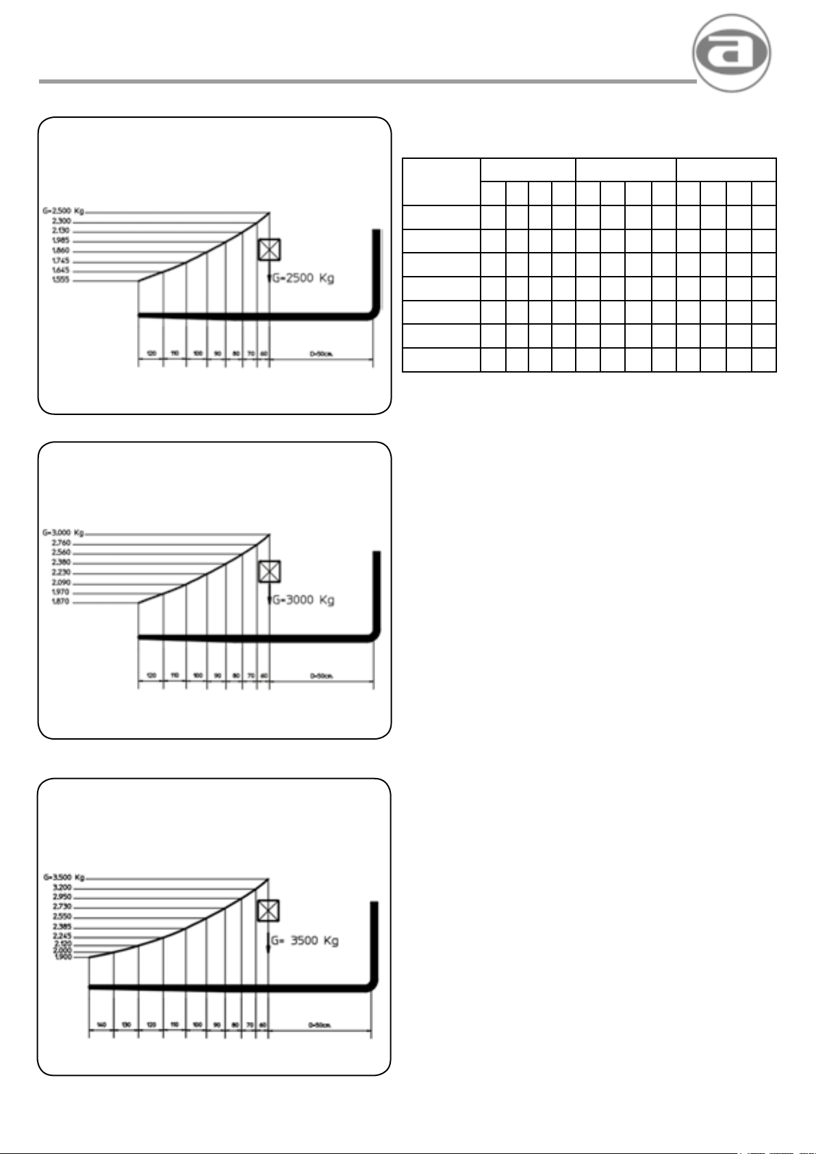
CUADRO DE CARGAS TH-250
LOAD CHART
TABLEAU DE CHARGEMENT
Mástil
TH-250 TH-300 TH-350
H5 H1 H6 H4 H5 H1 H6 H4 H5 H1 H6 H4
CUADRO DE CARGAS TH-300
LOAD CHART
TABLEAU DE CHARGEMENT
DUPLEX 314
DUPLEX 360
DUPLEX 425
TRIPLEX 400
TRIPLEX 450
TRIPLEX 500
TRIPLEX 600
TH-250: Tablero FEM 11B ancho 1300, con desplazador, horquillas 120x40x1200
TH-300: Tablero FEM 111B ancho 1300, con desplazador, horquillas 120x45x1200
TH-350: Tablero FEM 111B ancho 1800, con desplazador, horquillas 125x45x1400
PUESTO DE CONDUCCION
• Plataforma abatible montada sobre amortiguadores,
con visibilidad total y diseño ergonómico.
• Acceso por ambos lados. Mandos laterales.
• Asiento con suspensión y amortiguación, con regulaciones
de longitud, altura y peso.
Panel de instrumentos integral con los siguientes elementos:
• Cuenta revoluciones y cuenta horas
• Indicador de temperatura
• Indicador de nivel de combustible
• Controles de carga de batería, presión de aceite, luces,
intermitente, freno de estacionamiento.
• Llave de arranque con bloqueo
• Mando de cambio luces, intermitente y claxon
• Caja de fusibles
3140 2270 3820 3140 2360 3820
3600 2500 4280 3600 2580 4280 3600 2580 4280
4250 2825 4930 4250 2905 4930
4500 2270 5180 1570 4500 2360 5180
5000 2500 3140 1800 5000 2580 5680
6000 2825 3140 2124 6000 2905 6680
CUADRO DE CARGAS TH-350
LOAD CHART
TABLEAU DE CHARGEMENT
CAPACIDADES
• TH-250
Capacidad de carga con centro de gravedad a 500 mm. - 2.500 Kg.
• TH-300
Capacidad de carga con centro de gravedad a 500 mm. - 3.000 Kg.
• TH-350
Capacidad de carga con centro de gravedad a 500 mm. - 3.500 Kg.
NOTA:
Ver indicaciones en el apartado de manipulación de carga
Depósito de combustible 60 L
Depósito de aceite hidraulico 60 L
PESOS
TH-250 (2RM) con mástil DUPLEX 3.800 Kg
TH-250 (4RM) con mástil DUPLEX 3.950 Kg
TH-300 (4RM) con mástil DUPLEX 4.300 Kg
TH-350 (4RM) con mástil DUPLEX 4.750 Kg
EQUIPOS OPCIONALES
• Mástiles Duplex y Triplex con altura de elevación, según pedido
• Horquillas de diversas medidas.
• Cuchara para áridos de 500 L
• Barredora
• Cabina
• Aplicación de 4ª Válvula
16
Page 17

agria hispania, s.l.
TECHNICAL DATA DONNEES TECHNIQUES
Masts
DUPLEX 314
DUPLEX 360
DUPLEX 425
TRIPLEX 400
TRIPLEX 450
TRIPLEX 500
TRIPLEX 600
TH-250 TH-300 TH-350
H5 H1 H6 H4 H5 H1 H6 H4 H5 H1 H6 H4
3140 2270 3820 3140 2360 3820
3600 2500 4280 3600 2580 4280 3600 2580 4280
4250 2825 4930 4250 2905 4930
4500 2270 5180 1570 4500 2360 5180
5000 2500 3140 1800 5000 2580 5680
6000 2825 3140 2124 6000 2905 6680
TH-250: Dashboard FEM 11B-1300, with lateral offret forks of 120x40x1200
TH-300:
TH-350:
Dashboard
Dashboard
FEM 111B-1300,
FEM 111B-1800,
with lateral offret forks of
with lateral offret forks of
120x45x1200
125x45x1400
DRIVING POST
• Central, ample, ergonomic driving post.
• Acces from either side.
• Seat with suspension and cushioning, lenght, heigh
and weight adjustment.
Built-in instrument panel tted with:
• Rev counter and hour counter
• Temperature indicator
• Fuel level indicator
• Battery charge, oil pressure, lights, intermittent ligh parking
brake controls.
• Ignition key with blocking device
• Lights key with blocking device
• Fuse box
CAPACITIES
• TH-250
Load capacity with 500 mm. center of gravity - 2.500 Kg.
• TH-300
Load capacity with 500 mm. center of gravity - 3.000 Kg.
• TH-350
Load capacity with 500 mm. center of gravity - 3.500 Kg.
NOTE:
See information in the section of cargo handing
Masts
DUPLEX 314
DUPLEX 360
DUPLEX 425
TRIPLEX 400
TRIPLEX 450
TRIPLEX 500
TRIPLEX 600
TH-250 TH-300 TH-350
H5 H1 H6 H4 H5 H1 H6 H4 H5 H1 H6 H4
3140 2270 3820 3140 2360 3820
3600 2500 4280 3600 2580 4280 3600 2580 4280
4250 2825 4930 4250 2905 4930
4500 2270 5180 1570 4500 2360 5180
5000 2500 3140 1800 5000 2580 5680
6000 2825 3140 2124 6000 2905 6680
TH-250: Tablean FEM 11B largeur 1300, avec desplacement lateral fourches de 120x40x1200
TH-300: Tablean FEM 111B largeur 1300, avec desplacement lateral fourches de 120x45x1200
TH-350: Tablean FEM 111B largeur 1800, avec desplacement lateral fourches de 125x45x1400
POSTE DE CONDUITE
• Poste de conduite central, ample et ergonomique.
• Accès par les deux côtés. Commandes latérales.
• Siège avec suspension et amortissement, avec des régulations
de longeur, de hauteur et de poids.
Panneau d’instruments intégrale, avec les éléments suivants:
• Compte-tours et compteur d’heures
• Indicateur de température
• Indicateur du niveau de combustible
• Contrôles de charge de batterie, de pression d’huile,
de lumières, de clignotants, de frein de stationnement.
• Clé de démarrage avec verrouillage
•
Commande de changement de lumières, de clignotants et de Claxon
• Boîte à fusibles
CAPACITIES
• TH-250
Capacité de chargement avec centre de gravité á 500 mm. - 2.500 Kg.
TH-300
•
Capacité de chargement avec centre de gravité á 500 mm. - 3.000 Kg.
• TH-350
Capacité de chargement avec centre de gravité á 500 mm. - 3.500 Kg.
NOTE:
Voir les informations dans la section de la manipulations de
chargements
Carburant tank 60 L
Hydraulic oil tank 60 L
WEIGHT
TH-250 (2WD) with mast DUPLEX 3.800 Kg
TH-250 (4WD) with mast DUPLEX 3.950 Kg
TH-300 (4WD) with mast DUPLEX 4.300 Kg
TH-350 (4WD) with mast DUPLEX 4.750 Kg
OPTIONAL EQUIPMENT
• Duplex and Triplex mast, under order conrmation
• Varions fork highs.
• Loading shovel of 500 L
• Sweeper
• Cabin
• Application of 4ª Valve
Réservoir de combustible 60 L
Réservoir d’huile hydraulique 60 L
PESOS
TH-250 (2RM) avec mâts DUPLEX 3.800 Kg
TH-250 (4RM) avec mâts DUPLEX 3.950 Kg
TH-300 (4RM) avec mâts DUPLEX 4.300 Kg
TH-350 (4RM) avec mâts DUPLEX 4.750 Kg
EQUIPEMENTS OPTIONNELS
• Differents mâts en hauteur differentes fourches en longeur
• Fourches diverses mesures.
• Cuillère à sec 500 L
• Pelle chargeuse
• Cabine
• Application de 4ª Valve
17
Page 18
agria hispania, s.l.
DATOS TECNICOS
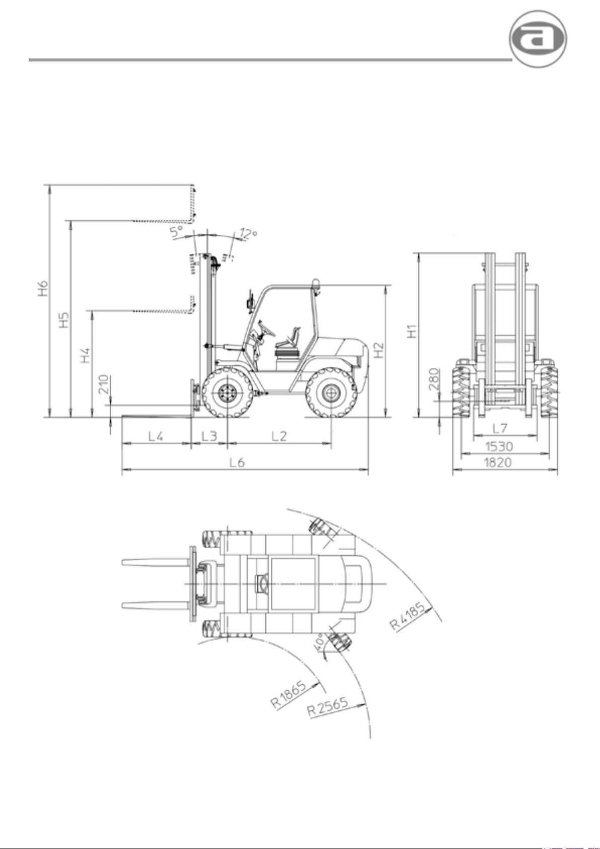
DIMENSIONES • DIMENSIONS • DIMENSIONS
18
Page 19

agria hispania, s.l.
TECHNICAL DATA DONNEES TECHNIQUES
DIMENSIONES • DIMENSIONS • DIMENSIONS
MASTIL
MASTS
MATS
DUPLEX 314
DUPLEX 360
DUPLEX 425
TRIPLEX 450
TRIPLEX 500
TRIPLEX 600
MASTIL
MASTS
MATS
DIMENSIONES • DIMENSIONS • DIMENSIONS
TH-250
H1 H2 H3 H4 H5 H6 L1 L2 L3 L4 L5 L6 L7 L8 L9 L10 L11 R1 R2
2270 3140 3820
2500 3600 4280
2850 2280 215 4250 4930 645 1800 646 1200 1675 4250 1300 1530 1820 6100 3100 1800 4250
2270 1570 4500 5180
2500 1800 5000 5680
2820 2120 6000 6680
DIMENSIONES • DIMENSIONS • DIMENSIONS
TH-300
H1 H2 H3 H4 H5 H6 L1 L2 L3 L4 L5 L6 L7 L8 L9 L10 L11 R1 R2
DUPLEX 314
DUPLEX 360
DUPLEX 425
TRIPLEX 450
TRIPLEX 500
TRIPLEX 600
MASTIL
MASTS
MATS
DUPLEX 314
DUPLEX 360
DUPLEX 425
2360 3140 3820
2580 3600 4280
2900 2360 250 4250 4930 645 1800 651 1200 1675 4255 1300 1640 1950 6100 3100 1800 4250
2360 1570 4500 5180
2580 1800 5000 5680
2900 2120 6000 6680
DIMENSIONES • DIMENSIONS • DIMENSIONS
TH-350
H1 H2 H3 H4 H5 H6 L1 L2 L3 L4 L5 L6 L7 L8 L9 L10 L11 R1 R2
2580 2360 275 3600 4280 645 1800 576 1400 1976 4375 1300 1640 1950 6100 3100 1800 4250
TRIPLEX 450
TRIPLEX 500
TRIPLEX 600
19
Page 20
agria hispania, s.l.
INSTRUCCIONES DE USO
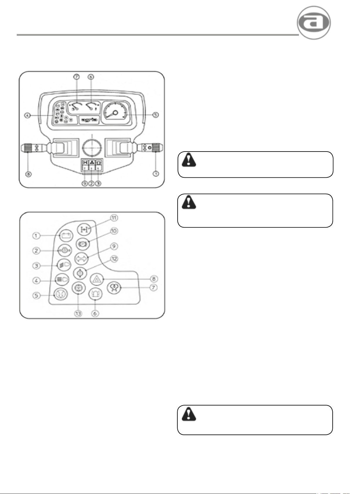
CUADRO DE INSTRUMENTOS
INSTRUMENT PANEL
TABLEAU D’INSTRUMENTS
CONTROL PRELIMINAR
Antes de poner en marcha una máquina nueva o después de un
largo período de reposo, es necesario:
1) Controlar el nivel de aceite en el cárter del motor
(véase el manual de mantenimiento del motor)
2) Controlar el nivel de aceite de los diferenciales y reductoras.
3) Controlar el nivel de aceite en el depósito hidráulico
y en el depósito del líquido de frenos.
4) Controlar la presión de los neumáticos.
No inar los neumáticos con gases inamables.
5) Controlar el nivel del líquido refrigerante. Para reponer el nivel,
añadir únicamente agua limpia en el depósito de expansión
(sólo en motores refrigerados por agua).
6) Asegurarse de que en el depósito del carburante haya
suciente combustible.
ATENCION
LLENAR EL DEPÓSITO LEJOS DE CUALQUIER LLAMA LIBRE.
7) Controlar que la batería esté cargada
INDICADORES
CONTROL • CONTROLE
1. - Carga de batería
- Battery charge
- Chargement de baterie
2. - Presión de aceite
- Oil pressure
- Pression d’huile
3. - Luz de cruce
- Dipped headlights
- Feu de croissement
4. - Luz de carretera
- Headlights on full beam
- Feu de route
5. - Colmatación ltro aire
- Air lter lled
- Plein air ltre
6. - Girofaro
- Headlight turning
- Pharetournant
7. - Calentador
- Heater
- Chauffant
8. - Emergencia
- Warning
- Émergence
9. - Indicador de dirección
- Direction indicator
- Clignotant
10.- Freno de estacionamiento
- Parking brake
- Frein d’estationnement
11.- Conexión 4 RM
- 4 WD conection
- Conection 4 RM
Temperatura aceite hidráulico
12.-
- Hydraulic oil temperature
Temperature de l’huile hydraulique
-
13.-
Colmatación aceite hidráulico
- Hydraulic lter oil overwelm
Colmatation du ltre d’huile hydraulique
-
ATENCION
ANTES DE CONTROLAR, LLENAR O RECARGAR LA BATERÍA,
HAY QUE APAGAR CUALQUIER TIPO DE LLAMA LIBRE.
NO FUMAR.
• CUANDO SE TRABAJE MUY CERCA DE LA BATERÍA,
HAY QUE PROTEGERSE DE LA SOLUCIÓN ÁCIDA.
SI DICHA SOLUCIÓN CAE SOBRE LA PIEL, LAVAR CON
AGUA ABUNDANTE Y SI SE PRODUCEN IRRITACIONES,
CONSULTAR A UN MÉDICO.
• DURANTE LAS OPERACIONES DE RECARGA,
QUITAR LOS TAPONES DE LOS ELEMENTOS.
8) Controlar que los tornillos que jan los órganos principales
(ruedas, bastidor, mástil, etc...) estén bien apretados, así como
el correcto encaje de las horquillas.
9) Asegurarse de que todos los órganos de mando, parada
y frenado funcionan correctamente.
RODAJE
En todo lo concerniente al motor, se tienen que seguir las
indicaciones contenidas en el manual de uso y mantenimiento del
mismo.
En cuanto a la máquina, no se precisan instrucciones especiales,
únicamente seguir detalladamente las instrucciones de este
manual.
CUADRO DE INSTRUMENTOS
1. - Mando de cambio de luces, indicadores de dirección y claxon
2. - Interruptor de luces de emergencia
3. - Interruptor de luz rotativa
4. - Caja de pilotos de control
5. - Cuentarevoluciones con cuentahoras
6. - Indicador de temperatura del motor
7. - Indicador del nivel de combustible
8. - Mando de inversor de marchas
9. - Interruptor de conexión 4 RM
ATENCION
PRESTAR MUCHA ATENCIÓN A LOS INDICADORES Y PILOTOS
DE CONTROL.
Cuando se encienda el piloto de reserva de combustible, parar
el motor y repostar. si se enciende el piloto de carga de batería,
presión de aceite o temperatura, parar el motor y avisar al Servicio
de Asistencia
20
Page 21
agria hispania, s.l.
OPERATING INSTRUCTIONS INSTRUCTIONS D’UTILISATION
PRELIMINARY CONTROL
Before starting a new machine or after an extended out-of-service
period.proceed as follows:
1) Check engine sump oillevel (see engine maintenance manual).
2) Check differential, and reduction box oil level.
3) Check hydraulic tank and brake uid container oil levels.
4)
Check tire pressure. Do not inate tires with inammable gases.
5) Check the refrigerating liquid level. To ll the level add only
clean water into the expansion tank
(only in water cooled engines).
6) Check that there is fuel enough into the fueltank.
ATTENTION
FILL TANK AWAV FROM FREE FLAME SOURCES
7) Check battery charge.
ATTENTION
BEFORE CHECKING,FILLING DR RECHARGING THE BATTERY,
EXTINGUISH ANY EXISTING NEARBY FREE FLAME.
REFRAIN FROM SMOKING
• WHEN WORKING CLOSE TO THE BATTERY, WATCH OUT
FOR THE ACID SOLUTION. IF SPILLED ON SKIN.RINSE
WITH ABUNDANT WATER. IN THE EVENT OF SKIN
IRRITATION, SEE A DOCTOR
• DURING RECHARGING, REMOVE THE BATTERY PLUGS
8) Check that all majar element (wheels, chassis, mast,etc.)
attachment screws are rmly tightened. Check that forks are
correctly tted.
9) Check that all control, stopping and braking components are
operating properly.
RUNNING-IN
In all aspects relating to the engine, follow the engine operation and
maintenance instructions in this manual.
No special instructions are needed for the machina. Simply follow
closely the instructions in this manual.
INSTRUMENT PANEL
1. - Light change control.direction change indicator and horn control
2. - Emergency light switch
3. - Beacon switch
4. • Control 1ights
5. - Rev counter with hour counter
6. - Engine temperatura indicator
7. - Fuellevelindicator
B. - Forward-Reverse control
9. - Conecting 4 WD switch
CONTROLE PRELIMINAIRE
Avant de mettre en marche une nouvelle machine ou apras une
longue période de repos, il est nécessaire de:
1) ContrOier le niveau d’huile dans le carter du moteur.
(Voir le manueld’entretien du moteur).
2)
Contrôler le niveau d’huile du différentiel et du boite de reduction.
3)
Contrôler
et dans le réservoir du liquide de freins.
4)
Contrôler
des gaz inammables.
5)
Contrôler
le niveau remplir seulement de l’eau net.dans le raservoir
d’expansion.
6) S’assuner que le réservoir du carburant a sufsamment de
combustible
le niveau d’huile dans le réservoir hydraulique
la pression des pneus. Ne pas goner les preus avec
le niveau de liquide de réfrigeration pour remettre
ATTENTION
REMPLIR LE RESERVOIR LOIN DE TOUTE SORTE DE FLAMME LIBRE
7)
Contrôler
que la batterie est chargée.
ATTENTION
AVANT DE CONTROLER, DE REMPLIR OUDE RECHARGER LA
BATTERIE, IL FAUT ETEINDRE TOUT E SORTE DE FLAMME LIBRE.
NE PAS FUMER
• LORSQU’ON TRAVAILLE TRES PRES DE LA BATTERIE,
IL FAUT SE PROTEGER CONTRE LA SOLUTION ACIDE.
SI CETTE SOLUTION TOMBE SUR LA PEAU, LAVER
AVEC DE L’EAU EN ABONDANCE ET SI DES IRRITATIONS
SE PRODUISENT, CONSULTER UN MEDECIN.
• PENDANT LES OPERATIONS DE RECHARGE, RETIRER
LES BOUCHONS DES ELEMENTS.
8)
Contrôler
(roues,chassis,mat.etc...) sont bien serrées,
ainsique l’emboltement correct des fourches.
9) S’assurer que tous les éléments de commande,d’arrêt
et de freinage fonctionnent correctement.
RODAGE
Pour tout ce quiconceme le moteur,ilfaut suivne les indications
contenues dans le manuel d’utilisation et d’entretien de celui-ci.
Quant a la machine.aucune instruction spéciales n’est nécessaire. il
suft de suivre de
fa on
TABLEAU D’INSTRUMENTS
1. - Commande de changement de lumieres, indicateurs
de direction et Klaxon
2. - lnterrupteur de lumiilres d’émergence
3. - lnterrupteur de la 1umiilre rotativa
4. - Bo1’te des pilotes de contrOle
5. - Compte-tours avec compteur d’heures
6. - lndicateur de température du moteur
7. - lndicateur du niveau de combustible
8. - Commande d’inverseur des marches
9. - lnterrupteur de conecttion 4 RM
que les vis qui xent les éléments principaux
ATTENTION
WATCH ALL CONTROL INDICATORS ANO LIGHTS CLOSELY
When the fuel tank reserve indicator 1ights up, stop the engine and
refuel. When the battery, oil pressure or temperatura indicators light
up,stop the engine and inform the TechnicalAssistance Service.
ATTENTION
ACCORDER BEAUCOUP D’ATTENTION AUX
INDICATEURS ET AUX PILOTES DE CONTROLE
Lorsque le pilote de ráserve de combustible s’allume, arrêter le
moteur et faire le plein. Si le pilote de la boíte de batterie, de la
pression de l’huile ou de la température s’allume, arrêter le moteur
et prévenir le Service d’assistance.
21
Page 22
agria hispania, s.l.
INSTRUCCIONES DE USO
MANDOS (Fig 1, 2, 3 y 4)
1. - Asiento
2. - Tirador de la apertura de la plataforma
3. - Mando desplazador del mástil
4. - Mando movimientos del mástil
5. - Mando de cambio de luces
6. - Volante
7. - Cuadro de instrumentos
8. - Llave de contacto y arranque
9. - Caja de fusibles
10. - Depósito de líquido de frenos
11. - Pedal de acelerador
12. - Pedal de freno / inching
14. - Tapón llenado aceite hidráulico
15. - Mando de inversor
16. - Palanca freno de estacionamiento
17. - Agarradero para levantar la plataforma
18. - Tapa de acceso a boca de llenado de combustible
19. - Varilla de nivel de aceite hidráulico
20. - Regulación longitudinal del asiento
21. - Regulación de la carga del asiento
PUESTA EN MARCHA DEL MOTOR
ATENCION
LA PUESTA EN MARCHA DEL MOTOR, ÚNICAMENTE SE DEBE
REALIZAR DESDE EL PUESTO DE CONDUCCIÓN
Para la puesta en marcha del motor operar de la siguiente forma:
1) Acceder al puesto de conducción y regular el asiento
adecuadamente al conductor.
2) El asiento dispone de regulación longitudinal, mediante el mando
20 (g. 4) y regulación de acuerdo al peso del conductor, mediante
el mando 21 (g. 4)
3) Situar el mando del inversor (15) en posición NEUTRAL
y asegurarse de que las horquillas del mástil están abajo.
4) Introducir la llave de arranque y girarlo a la posición de contacto
(se encienden las luces de testigo del cuadro de instrumentos).
ATENCION
LA MÁQUINA DISPONE DE UN DISPOSITIVO DE SEGURIDAD QUE
IMPIDE ARRANCAR EL MOTOR MIENTRAS QUE EL MANDO DEL
INVERSOR NO ESTÉ SITUADO EN LA POSICIÓN NEUTRAL
5) Una vez ASEGURADO de que no existe NADIE en la zona de
acción de la máquina, girar la llave a la posición de arranque
(START).
Una vez que el motor se ha puesto en marcha, soltar la llave para que
vuelva a la posición inicial (contacto).
Si el motor no se pone en marcha, no insistir con arranques
prolongados durante mas de 15 segundos. Para no descargar la
batería, efectuar las pruebas sucesivas, dejando algunos intervalos y
repetir la operación después de haber controlado:
a) Que el ltro de combustible no esté obstruido
b) Que la batería esté en perfectas condiciones
c) Que hay suciente combustible en el depósito
6) Antes de poner en marcha la máquina, mantener el motor
en ralentí 5 minutos. Es IMPORTANTE respetar esta indicación,
al inicio de la jornada y especialmente durante el período de
rodaje.
22
Page 23
agria hispania, s.l.
OPERATING INSTRUCTIONS INSTRUCTIONS D’UTILISATION
CONTROLS (Fig 1, 2, 3 and 4)
1. - Seat
2. - Platform opening hand lever
3. - Auxiliary distributor control
4. - Mast movement control
5. - Light ehange control
6. - Driving wheel
7. - lnstrument panel
8. - Contact and ignition key
9. - Fuse box
10. - Brake uid container
11. - Accelerator pedal
12. - Brake pedal
14. - Hydraulic oillling plug
15. - lnverter control
16. - Parking brake lever
17. - Gear box cover raising handle
1B. - Cover access to fuel tank plug
19. - Hydraulic oillevel rod
20. - Longitudinal regulation of the seat
21. - Weight regulation of the seat
STARTING THE ENGINE
ATENCION
START THE ENGINE ONLY FROM THE DRIVING POST
To start the engine, proceed as follows:
1) Occupy the driving post and adjust the driver’s seat
2) The seat is longitudinally adjustable by means of levar 20 (Fig. 4)
and load adjustable. according to the driver’s weight. by means of
levar 21 (Fig. 4).
3) Place the inverter control (15) in NEUTRAL position and ensure
that the mast forks are down.
4) lnsert the ignition key and rotate it to the contact position
(the instrument panel controllights will turn on).
COMMANDES (Fig 1, 2, 3 et 4)
1. - Siège
2. - Manette pour ouvrir la platteforme
3. - Commande de distribution auxiliaire
4. - Commande de mouvements du mat
5. - Commande de changement de lumiéres
6. - Volant
7. - Tableau d’instruments
B. - Clé de contact et de démarrage
9. - Bolte des fusibles
10. - Réservoir du liquide de freins
11. - Pédale de l’accélérateur
12. - Pédale du frein
14. - Bouchon de remplissage d’huile hydraulique
15. - Commande de l’ nverseur
16. - Levier du frein de stationnement
17. - Poignée pour soulever le couvercle de la bolte de changement
de vitesses
1B. - Couvercle du réservoir de combustible
19. - Tige du niveau d’huile hydraulique
20. - Régulation longitudionaldu siége
21. - Régulation du poids du siége
MISE EN MARCHE DU MOTEUR
ATENCION
LA MISE EN MARCHE DU MOTEUR DOIT SE REALISER
UNIQUEMENT DEPUIS LE POSTE DE CONDUITE
Pour la mise en marche du moteur,opérer de la facon suivante :
1) Accéder au poste de conduite et régler le sil!ge au conducteur
de facon adéquate.
2) Le siége dispose d’une régulation longitudinale, au moyen de la
commande 2. (Fig. 4) et d’une régulation selon le poids du
conducteur. au moyen de la commande 21 (Fig.4).
3) Situer le levier de vitesses (5) et le commande de l’inverseur
(15) en position NEUTRE et s’assurer que les fourches du
mat sont baissées.
4) Introduire la cié de démarrage et la tourner vers la position de
contact (les lumières témoins du tableau d’instruments s’allument).
ATENCION
THE MACHINE HAS A SECURITY DEVICE WHICH AVOID START
THE ENGINE WHILE THE INVERSOR CONTROL IS NOT IN
NEUTRAL POSITION.
5) MAKE SURE that NOBODY is within operating ranga of the
machine and turn the key to the START position. Once the engine
is running, release the key, which automatically returns to the initial
position.
l fthe engine does not start.do not insist with long starting attempts for
more than 15 seconds. To not unload the battery do the successive tries
with sorne intervals and repeat the action after checking:
a) That the fuel lter is not obstructed
b) That the battery is in perfect conditions
c) That there is enough fuel inside the tank
6) Befare putting the machina in motion.keep the engine at idling
speed for 5 minutes. This is IMPORTANT at the beginning of
the day, particularly in the Running-in period
23
ATENCION
LA MACHINE EST EQUIPÉE AVEC UN DISPOSITIF DE
SECURITÉ,QUI NE PERMETTE PAS DEMARRER LE MOTEUR,
QUAND LE COMMANDE DE L’INVERSEUR NE SOIT PAS PLACE
DANS LA POSITION POIN MORT.
5) Une fois ASSURE qu’il n’existe PERSONNE dans la zone d’action
de la machine, tourner la cié vers la position de DEMARRAGE.
Lorsque le moteur s’est mis en marche,lllcher automatiquement
a la position initiale.
Si le moteur ne demarre pas. Ne pas insister avec des temtatives
prolongees pendant une periode superieure :.t 15 seconds. Pour evitar
la décharge de la battene,faire des tentativas sucesivas mais avec des
intervalles et répéter l’operation apres avoir controle:
a) Que le ltre du combustible ne soit pas obture
b) Que la batterie soit en parfaie état
c) Qu’il y a de combustible dans le reservoir
6) Avant de mettre enmarche la machina.maintenir le moteur au
ralenti pendant 5 minutes Il est IMPDRTANT de respectar cette
indication.en commencant la journée de travail et notamment
pendant la période de Rodage.
Page 24
agria hispania, s.l.
INSTRUCCIONES DE USO
I
PUESTA EN MARCHA DE LA MÁQUINA
ATENCION
ANTES DE PONER EN MARCHA LA MAQUINA ASEGURARSE QUE
LA CARGA ESTA BIEN POSICIONADA, Y QUE EL MASTIL ESTA
INCLINADO HACIA ATRAS.
EXAMINAR SIEMPRE CON MUCHA ATENCIÓN LA ZONA PARA
BUSCAR POSIBLES CAUSAS DE PELIGRO Y ACTUAR EN
II
CONSECUENCIA.
PONER EN MARCHA LA MAQUINA DESPUES DE HABER
CONTROLADO QUE NO HAYA NADIE EN SU RADIO DE ACCION.
Para la puesta en marcha de la máquina, operar de la siguiente forma:
1) Dejar que el motor gire en ralentí.
2) Situar el mando del inversor 15 (Fig. 1) en la posición de marcha
deseada, de acuerdo a las indicaciones de la gura 5.
3) Acelerar suavemente para conseguir el desplazamiento de la
máquina
ATENCION
ANTES DE PONER EN MARCHA LA MAQUINA, ASEGURARSE DE
QUE EL FRENO DE ESTACIONAMIENTO ESTA DESCONECTADO.
ATENCION
NO PISAR BRUSCAMENTE EL PEDAL DEL FRENO, PORQUE LA
MÁQUINA SE PARARA TAMBIEN BRUSCAMENTE.
CON EL PEDAL DE FRENO PISADO, LA MAQUINA NO SE
DESPLAZA Y SE PUEDE ACELERAR EL MOTOR AL MAXIMO PARA
OBTENER MOVIMIENTOS RAPIDOS DEL MASTIL.
CON EL MOTOR ACELERADO Y SOLTANDO LENTAMENTE EL
PEDAL DEL FRENO SE PUEDEN OBTENER MOVIMIENTOS
LENTOS Y ACERCAMIENTOS DE PRECISION DE LA MAQUINA.
Para invertir el sentido de marchas es recomendable parar la máquina
y después accionar el mando del inversor.
PARADA DE LA MÁQUINA
ATENCION
APARCAR LA MAQUINA EN TERRENO FIRME Y CON EL FRENO
DE MANO CONECTADO.
SI LA MAQUINA SE PARA EN UNA PENDIENTE HAY QUE PONER
UNA CUÑA DEBAJO DE LA RUEDA.
NO ABANDONAR NUNCA LA MAQUINA CON EL MOTOR EN
MARCHA NI CON LA LLAVE DE ARRANQUE PUESTA.
1) Soltar suavemente el acelerador, pisar el pedal de FRENO y situar
en posición NEUTRAL el mando del inversor.
2) Accionar el freno de estacionamiento, inclinar el mástil hacia
atrás y bajar las horquillas hasta el suelo. Asegurarse de
la correcta inclinación de la carga.
3) Girar la llave a la posición de STOP para obtener la parada del
motor y retirarla.
24
Page 25
agria hispania, s.l.
OPERATING INSTRUCTIONS INSTRUCTIONS D’UTILISATION
STARTING THE MACHINE
ATTENTION
BEFORE STARTING THE MACHINE, MAKE SURE THAT THE
LOAD IS PROPERLY POSITIONED AND THE MAST IS TILTED
BACKWARDS.
CAREFULLY INSPECT THE AREA TO SEARCH FOR POSSIBLE
HAZARDS,AND ACT ACCORDINGLY.
BEFORE STARTING THE MACHINE,CHECK THAT
NOBODY IS WITHIN OPERATING RANGE
To start the machine,proceed as follows:
1) Let the engine tums in ralenti.
2) Put the inversor lever 15,Fig.1 into the desired gear.according
to the indications ofthe Fig. 5
3) Accelerate slightly to get the displacement of the machine.
ATTENTION
BEFORESTART THEMACHNI E,BESURE THATTHE PARKING
BRAKE IS DISCONNECTED
ATTENTION
MISE EN MARCHE DE LA MACHINE
ATTENTION
AVANT DE METTRE EN MARCHE LA MACHINE, S’ASSURER QUE
LE CHARGEMENT EST EN BONNE PDSITION ET QUE LE MAT EST
INCUNE VERS L’ARRIERE.
EXAMINER TOUJOURS AVEC BEAUCOUP D’ATTENTION LA
ZONE POUR CHERCHER DE POSSIBLES DANGERS ETAGIR EN
CONSEQUENCE.
METTRE EN MARCHE LA MACHINE UNIQUEMENT APRES
AVOIR CONTROLE QU’IL N’Y A PERSONNE DANS SON RAYON
D’ACTION.
Pour la mise en marche de la machine, op!!rer de la fa¡¡on suivante:
1) Laiser que le moteur tourne en ralenti.
2) Placer la commande de l’inverseur 15, Fig.1 dans la position
de marche desirne,en suivant les indications du FIg. 5.
3) Accélerer doucement pour obtenir le deplacement de la machine.
ATTENTION
AVANT LA MISE EN MARCHE DE LA MACHINE IL FAUT
S’ASSURER QUE LE FREIN DE STATIONNÉMENT SOIT
DÉBRANCHÉ.
DO NOT PUSH THE INCHING PEDAL BRUSQUELY BECAUSE THE
MACHINE WILL STOP BRUSQUELY.
WITH THE INCHING PEDAL PUSHED,THE MACHINE DOES
NOT START MOVING ANO THE ENGINE CAN BE ACCELERATED
TO THE MAXIMUM GET FAST MOVEMENTS OFTHEMAST.
WITH THE ENGINE ACCELERATED ANO RELEASEING SLOWLY
THE INCHING PEDAL THE MACHINE CAN GET SLOW
‘-MOVEMENTS ANO ACCURATE APPROACHINGS.
To invert the direction of the gears it is recommended to stop the
machine and, after,work the inversor lever.
STOPPING THE MACHINE
ATTENTION
PARKTHE MACHINE ON FIRM GROUND ANO APPLYTHE PARKING
BRAKE.
IF THE MACHINE STOPS ON A SLOPE,PLACE A WEDGE UNDER
A WHEEL.
NEVER LEAVE THE MACHINE WHILE THE ENGINE
RUNNING;NEITHER WITH THE IGNITION KEY INTRODUCED
1) Slowly ralease the accelerator pedal,step on the BRAKE pedal
and place the inverter control in NEUTRAL
2) Apply the parking brake,tilt the mast backwards and lower the forks
down to ground level. Make sure that the load is properly placed.
3) Turn the key to the STOP position to stop the engine and
release it.
ATTENTION
NE PAS PRESSER BRUSQUEMENT LA PÉDALE INCHING
PARCE QUE LA MACHINE S’ARRETERA BRUSQUEMENT. AVEC
LA PÉDALE INCHING PRESSEE. LA MACHINE N’A PAS DE
DEPLACEMENT ET LE MOTEUR PEUT ETRE ACCELERÉ AU
MAXIMUM POUR OBTENIR DES MDUVEMENTS RAPIDES DU MAT.
AVEC LE MOTEUR ACCELERÉ.EN LACHANT LENTEMENT LA
PEDALE INCHING S’OBTIENENT DEMOUVEMENTS LENTES
ET DES RAPPROCHEMENTS DE PRECISION DE LA MACHINE.
Pour inverser le sens desmarches il est recommendable arréter la
machine et aprés actionner la commande de l’inverseur.
ARRET DE LA MACHINE
ATTENTION
SI LA MACHINE S’ARRETE DANS UNE PENTE, IL FAUT METTRE
UNE CALE SOUS LA ROUE.
NE JAMAIS ABANDONNER LA MACHINE AVEC LE MOTEUR
EN MARCHE, NI AVEC LA CLE DE DEMARRAGE MISE.
1) Lâcher doucement l’accélérateur,appuyer le pédale de FREIN
et situar en position NEUTRE la commande de l’inverseur.
2) Mettre en place le frein de stationnement,incliner le mat vers
l’arrière et baisser les fourches jusqu’au sol. S’assurer de
la situation correcte du chargement.
3) Tourner la cié á la position du STOP, pour arreter le moteur
et retirer la même.
25
Page 26

agria hispania, s.l.
INSTRUCCIONES DE USO
MANIPULACIONES DE CARGAS
Los movimientos del mástil se controlan con el mando (4). Este mando
acciona los movimientos de elevación y descenso del mástil, así como la
inclinación de acuerdo a las indicaciones de la Fig. 6.
Para el accionamiento de movimientos adicionales (desplazador, cuchara,
etc..) la máquina está equipada con un distribuidor auxiliar que se
gobierna con el mando (3) y de acuerdo con las indicaciones de la Fig. 7.
ATENCION
EN LA MANIPULACION DE LAS CARGAS, RESPETAR LAS
CAPACIDADES INDICADAS EN EL CUADRO DE CARGAS.
RESPETAR LAS NORMAS DE SEGURIDAD.
RECOMENDACIONES ADICIONALES EN LA MANIPULACIÓN DE
CARGAS
1) Antes de acercarse a la carga, asegurarse que dispone del acceso
adecuado para las horquillas y situar éstas a la anchura adecuada.
2) No sobrepasar los límites de capacidad de carga ni las distancias
de su centro de gravedad.
3) Utilizar los mandos de control del mástil con suavidad y evitar
movimientos bruscos.
Antes de subir o bajar carga pisar el pedal del FRENO y situar el
4)
mando del inversor en posición NEUTRAL. Conectar el freno de mano.
5) Si se utilizan accesorios adicionales para manipulación de cargas
atender a sus instrucciones especícas sobre conexión y maniobra.
,
NORMAS DE SEGURIDAD
PROHIBIDO:
1) Sobrecargar la carretilla
2) Circular con la carga elevada
3) Efectuar giros a velocidad brusca
4) Frenar bruscamente
5) Transportar personas
ADVERTENCIAS:
1) Para evitar riesgos de vuelco, antes de elevar la carga,
ASEGURARSE de que la máquina está situada en una posición
estable y sobre terreno rme.
2) Para asegurar la estabilidad de la máquina, se RECOMIENDA,
reducir la capacidad de elevación nominal, como sigue:
- Altura de elevación hasta 5,5 m: 75% de la capacidad nominal.
- Altura de elevación a partir de 6 m: 50% de la capacidad nominal.
OBLIGATORIO:
1) Circular con la carga, aprox. a 30 cm. del suelo y con el mástil
inclinado hacia atrás.
2) Descender las pendientes en marcha atrás y subir en marcha
adelante.
3) La carretilla debe ser utilizada únicamente por personal autorizado
y debidamente instruído.
4) Poner en marcha la carretilla y accionar los mandos
UNICAMENTE desde el puesto de conducción.
5) Comprobar el correcto funcionamiento de los elementos de mando
y alarma.
6) Si durante el trabajo se observa cualquier anomalía, detener la
máquina y acudir al servicio de mantenimiento.
7) Asegurar una buena ventilación cuando se trabaja en interiores.
8) Antes de abandonar la carretilla:
• Situar las horquillas en posición horizontal y al ras del suelo.
• Poner el mando del inversor en posición NEUTRAL
• Accionar el freno de mando
• Parar el motor y quitar la llave de arranque.
9) Si se debe dejar la carretilla estacionada en una pendiente,
además de las indicaciones anteriores, colocar calzos adecuados
en las ruedas.
10) Ceder el paso a la derecha a los peatones y demás vehículos.
11) Antes de manipular cargas de un camión o remolque, asegurarse
que se encuentra frenado y adecuadamente situado.
12) Si se utilizan accesorios adicionales, consultar antes la carga
admisible con la nueva situación.
13) Circular con la carga en posición baja, aprox. a 30 cm. del suelo.
14) Circular sobre suelo consistente y libre de obstáculos.
15) Operar siempre con prudencia manteniendo en todo momento
el control sobre la carretilla y su carga.
26
Page 27

agria hispania, s.l.
OPERATING INSTRUCTIONS INSTRUCTIONS D’UTILISATION
LOAD HANDLING
Mast movements are controlled via controll4). This acts en the
raising,lowering and tilting movements of the mast.as shown in Fig.6.
For other movements lshifter, bucket,etc.), the machine is equipped with
an auxiliary distributor governed through control 13), as shown in Fig. 7
ATTENTION
WHEN HANDLING LOADS.ADHERE TO THE CAPACITIES
INDICATED IN THE LOAD CHART
OBSERVE ALL SAFETY REGULATIONS
ADDITIONAL LOAD HANDLING RECOMMENDATIONS
1) Before approaching the load,make sure that adequate access is
available for the forks;adjust the forks to their proper width.
2) Exceed neither the load capacity nor the center of gravity
distances.
3) Handle the mast controls softly,avoiding abrupt motions.
4) Before raising or lowering the load, step on the BRAKE pedal
and place the inverter control in NEUTRAL position. Apply the
parking brake.
5) If additional accessories are used for load handling purposes.
observe their specic instructions in regard to connections and
manoeuvres.
SAFETY REGULATIONS
FORBIDDEN:
1) Overloading the fork 1ifter
2) Circulating with an elevated load
3) Making abrupt turns at high speed
4) Making sudden stops
5) Transporting persons
WARNINGS
1) To avoid risk of rollover, befote raising the load SURE that the
machine is located in a estable position and rm ground sonre
2) To ensure the stability of de machine it is RECOMMEDED to
reduce the nominal lifting capacity:
-Height of elevation up to 5,5 m: 75% of nominal capacity
-Height of elevation from 6,0 m: 50% of nominal capacity
OBLIGATORY:
1) Circulating with the load approximately 30 cm off the ground and
with the mast tilted backwards.
2) Driving down slopes in reverse and up slopes forwards.
3) Use of the fork lifter is restricted to authorised. duly trained
personnel.
4) The fork lifter must be started and its controls operated ONLY from
the driving post.
5) Check for correct operation of all control and alarm components.
6) If any anomaly is observad in operation,stop the machina and ca11
for technical assistance.
7) Make sure that proper ventilation is provided when working in a
closed environment.
8) Before leaving the fork lifter:
• Place the forks horizontal and at ground level
• Place the inverter control in NEUTRAL position
• Apply the parking brake
•Stop engine and remove the ignition key
9) When parking the fork lifter on a slope,install adequate wedges
on the wheels, in addition to observing the above instructions.
10) Allow passage on the right to passers-by and other vehicles.
11) Before handling loads from a truck or trailer, make sure that said
truck or trailer is properly parked and with the brakes on.
12) If additional accessories are used, check admissible 1oads.
13) Drive with the load in low position, approximately 30 cm from
the ground.
14) Drive over hard ground that is free of obstacles.
15) Always operate with caution, maintaining a permanent controlon
both the fork lifter and the load.
MANIPULATIONS DE CHARGEMENTS
Les mouvements du mât se contrôllent avec la commande (4).Cette commande
meten action les mouvements d’élévation et de descante du mllt,ainsi que
l’inclinaison,conformément aux indications de la Fig.6.
Pour la mise en action des mouvements additionnels (système de déplacement
cuillère,la machine est équipée avec un distributeur auxiliaire, qui se gouverne
avec la commande (3) et conformément aux indications de la Fig. 7.
ATTENTION
PENDANT LES MANIPULATIONS DES CHARGEMENTS.
RESPECTER LES CAPACITES INDIDUEES DANS LE TABLEAU DE
CHARGEMENTS.
RESPECTER LES NORMES DE SECURITE.
RECOMMANDATIONS ADDITIONNELLES PENDANT LA
MANIPULATION DE CHARGEMENTS
1) Avant de s’approcher au chargement. s’assurer qu’on dispose
de l’acc s adéquat pour les fourches et situer celles-ci à la largeur
adéquate.
2) Ne pas dépasser les limites de capacité de chargement. ni les
distances de son centre de gravité.
3) Utiliser les commandes de contrOle du mat avec douceur et éviter
les mouvements brusques.
4) Avant de monter ou de descendre le chargement, appuyer sur
le pedale de FREIN et situer le commande de l’inverseur en
position NEUTRE. Mettre en place le frein de stationnement.
5) Si on utilise des accessoires additionnels pour la manipulation du
chargement, suivre leurs instructions spéciques sur la connexion
et la manouvre.
NORMES DE SECURITE
INTERDIT:
1) Surcharger le chariot.
2) Circular avec le chargement élevé.
3) Effectuer des tournants a des vitesses brusques.
4) Freiner brusquement.
5) Transportar des personnes.
ATTENTION
1) Pour éviter tont risqué de basculement. avant de sonlever la
charge que la machine se trouve dans une position stable et
sonre la terre ferme
2) Pour assurer la stabilité de l’machine, il est RECOMMANDE de
réduire la capacité de elevage nominale:
- Hanteur d’elevation pusqu5,5 m:75% de la capacité nominale
- Hanteur d’elevation de 6,0 m: 50% de la capacité nominale
OBLIGATOIRE
1) Circuler avec le chargement,enviran a 30 cm. du sol et avec le mat
incliné vers l’arrière.
2) Descendre les pentes en marche arrière
3) Le chariot doit être utilisé uniquement par un personnel autorisé et
dûment instruit.
4) Mettre en marche le chariot et utiliser les commandes
UNIQUEMENT depuis le poste de conduite.
5) Vérier le fonctionnement correct des éléments de commande
et d’alarme.
6) Si pendant le travail on observe une quelconque anomalie, arrêter
la machine et faire appel au service d’entretien.
7)
Assurer une bonne ventilation,lorsqu’on travaille l’intérieur de locaux
8) Avant d’abandonner le chariot:
• Situer les fourches en position horizontale et a raz du sol
• Mettre la commande de l’inverseur en position NEUTRE.
• Mettre le frein a main.
• Arrêter le moteur et retirar la clé de démarrage.
9) Si on doit laisser le chariot stationné dans une pente,en plus des
indications antérieures.placer des cales adéquates sous les roues.
10) Donner priorité a droite aux piétons et aux autres véhicules.
11) Avant de manipular des chargements d’un camion ou d’une
remarque.s’assurer que celui-ci se trouve freiné et situé de fa on
12) Si on utilise des accessoires additionnels,consultar a l’avance le
chargement admissible avec la nouvelle situation.
13)
Circuler avec le chargement en position basse, enviren a 30 cm. du sol.
14) Circuler sur un sol consistant et libre d’obstacles.
15) Opérer toujours avec prudence en gardant, a tout moment, le
contrôle sur le chariot et sur son chargement.
.
27
Page 28

agria hispania, s.l.
MANTENIMIENTO
RECOMENDACIONES DE SEGURIDAD
ATENCION
ANTES DE EFECTUAR OPERACIONES DE CUALQUIER TIPO
EN LA MAQUINA, HAY QUE LEER ATENTAMENTE TODAS LAS
INSTRUCCIONES Y LAS NORMAS DE SEGURIDAD.
NO EFECTUAR OPERACIONES DE MANTENIMIENTO NI TAMPOCO
REPARACIONES O LUBRICACION CON LA MAQUINA EN
MOVIMIENTO, SALVO QUE LO INDIQUEN LAS INSTRUCCIONES
CORRESPONDIENTES.
SI SE TIENE QUE EFECTUAR ALGUNA OPERACION DE
MANTENIMIENTO CON EL MOTOR EN MARCHA, HAY QUE PEDIR
AYUDA A UN OPERADOR EXPERTO, CAPAZ DE MANTENER BAJO
CONTROL EL MOTOR Y DE INTERVENIR EN CASO NECESARIO.
NO PONER NUNCA EN MARCHA EL MOTOR EN AMBIENTES
CERRADOS, YA QUE EL GAS QUE DESCARGA ES MUY TOXICO.
SI SE TIENEN QUE SOLTAR LOS GRUPOS DE LA MAQUINA, HAY
QUE ASEGURARSE DE QUE ESTEN SOSTENIDOS POR EQUIPOS
ADECUADOS.
NO TRABAJAR NUNCA DEBAJO DE LA MAQUINA O DE ALGUNA DE
SUS PARTES, SIN QUE EL EQUIPO DE SOPORTE SEA SEGURO Y
CONFORME A LAS NORMAS DE SEGURIDAD.
DURANTE LAS INTERVENCIONES EN LA MAQUINA, NO UTILIZAR
NUNCA, COMO MEDIOS DE ILUMINACION, ENCENDEDORES,
CERILLAS U OTROS MEDIOS DE LLAMA LIBRE.
LIMPIAR LAS PIEZAS USANDO EXCLUSIVAMENTE DISOLVENTES
COMERCIALES HOMOLOGADOS, NO INFLAMABLES Y TOXICOS.
LAS POSIBLES INTERVENCIONES EN LA INSTALACION
HIDRAULICA TIENEN QUE EFECTUARSE SIEMPRE DESPUES DE
HABER DESCARGADO COMPLETAMENTE LA PRESION DEL ACEITE
DEL CIRCUITO.
NO LLEVAR NUNCA VESTIDOS DEMASIADO AMPLIOS CUANDO SE
TRABAJE CERCA DE ORGANOS EN MOVIMIENTO.
CUANDO SEA NECESARIO UTILIZAR HERRAMIENTAS ESPECIALES
PARA EFECTUAR EL MANTENIMIENTO DE LA MAQUINA, HAY QUE
ASEGURARSE DE QUE SEAN CONFORMES A LAS NORMAS DE
SEGURIDAD.
NO REGULAR NUNCA LA BOMBA DE ALIMENTACION DEL
COMBUSTIBLE CON EL MOTOR EN MARCHA.
28
Page 29

agria hispania, s.l.
MAINTENANCE ENTRETIEN
SAFETY INSTRUCTIONS
ATTENTION
BEFORE PERFORMING ANY TYPE OF OPERATION ON THE
MACHINE,CAREFULLY READ THE INSTRUCTIONS AND SAFETY
RULES.
DO NOT PERFORM MAINTENANCE,REPAIR OR LUBRICATION
TASKS WHILE THE MACHINEIS MOVING UNLESS INDICATED IN
THE INSTRUCTIONS.
IN THE EVENT OF PERFORMING MAINTENANCE OPERATIONS
WHILE THE ENGINE IS RUNNING.GET HELP FROM AN EXPERT
OPERATOR CAPABLE OF KEEPING THE ENGINE UNDER
CONTROL ANO HANDLING THE SITUATION AS NECESSARY.
NEVER AUN THE ENGINE IN CLOSED ENVIRONMENTS,SINCE
THE EXHAUST FUMES ARE HIGHLY TOXIC.
WHEN REMOVING MACHINE COMPONENTS.MAKE SURE
THAT THEY ARE HELD BY ADEQUATE MEANS.
NEVER WORK UNDER THE MACHINE OR UNDER A MACHINE
COMPONENT WITHOUT SAFE SUPPORTING MEANS, IN
COMPLIANCE WITH APPLICABLE SAFETY REGULATIONS
WHEN WORKING ON THE MACHINE, NEVER USE LIGHTERS,
MATCHES OR OTHER FREE FLAME MEANS FOR LIGHTING
PURPOSES.
RECOMMENDATIONS DE SECURITÉ
ATTENTION
AVANT D’EFFECTUER DES OPERATIONS DE TOUTE SORTE
AVEC LA MACHINE, IL FAUT LIRE ATTENTIVEMENT TOUTES LES
INSTRUCTIONS ET LES NORMES DE SECURITE.
NE PAS EFFECTUER D’OPERATIONS D’ENTRETIEN, NI DE
REPARATIONS OU DE LUBRIFICATIONS AVEC LA MACHINE EN
MOUVEMENT, SAUF SI LES INSTRUCTIONS CORRESPONDANTES
L’INDIQUENT.
SI ON DOIT EFFECTUER CERTAINES OPERATIONS D’ENTRETIEN
AVEC LE MOTEUR EN MARCHE, IL FAUT DEMANDER DE L’AIDE A
UN OUVRIER EXPERT, CAPABLE DE GARDER SOUS CONTROLE
LE MOTEUR ET D’INTERVENIR EN CAS DE BESOIN.
NE JAMAIS METTRE LE MOTEUR EN MARCHE DANS DES
ENCEINTES FERMEES. CAR LE GAZ DEGAGE EST TRES
TOXIQUE.
SI ON DOIT LACHER LES GROUPES DE LA MACHINE, IL FAUT
S’ASSURER QU’ILS SONT FIXES PAR DES EOUIPEMENTS
ADEQUATS.
NE JAMAIS TRAVAILLER SOUS LA MACHINE OU SOUS AUCUNE
DE SES PARTIES, SANS QUE L’EQUIPEMENT DE SUPPORT SOIT
ASSURE ET CONFORME AUX NORMES DE SECURITE.
PENDANT LES INTERVENTIONS SUR LA MACHINE, NE JAMAIS
UTILISER, COMME MOYENS D’ECLAIRAGE, DES BRIQUETS, DES
ALLUMETTES OU D’AUTRES MOYENS AVEC FLAMME LIBRE.
CLEAN PARTS USING ONLY HOMOLOGATED COMMERCIAL
SOLVENTS- NEVER USE INFLAMMABLE OR TOXIC SOLVENTS.
WORK ON THE HYDRAULIC SYSTEM MUST NEVER BE
PERFORMED BEFORE FULLY RELEASING THE CIRCUIT OIL
PRESSURE.
NEVER WEAR EXCEEDINGLY LOOSE GARMENTS WHEN
WORKING NEAR MOVING PARTS.
WHEN USING SPECIAL MACHINE MAINTENANCE TOOLS.
MAKE SURE THATTHEY CONFORM TO SAFETY REGULATIONS.
NEVER ADJUST THE FUEL SUPPLY PUMP WHILE THE ENGINE IS
RUNNING.
NETTOYER LES PIECES EN UTILISANT EXCLUSIVEMENT DES
SOLVANTS COMMERCIAUX HOMOLOGUES, NON
INFLAMMABLES, NI TOXIQUES.
LES POSSIBLES INTERVENTIONS DANS L’INSTALLATION
HYDRAULIQUE DOIVENT TOUJOURS S’EFFECTUER APRES
AVOIR DECHARGE COMPLETEMENT LA PRESSION DE L’HUILE
DU CIRCUIT.
NE JAMAIS PORTER DE VETEMENTS TROP AMPLES
LORSQU’ON TRAVAILLE PRES D’ELEMENTS EN MOUVEMENT.
LORSQU’IL SOIT NECESSAIRE D’UTILISER DES OUTILS
SPECIAUX POUR EFFECTUER L’ENTRETIEN DE LA MACHINE, IL
FAUT S’ASSURER OU’ILS SONT CONFORMES AUX NORMES DE
SECURITE.
NE JAMAIS REGLER LA POMPE D’ALIMENTATION DU
COMBUSTIBLE AVEC LE MOTEUR EN MARCHE.
29
Page 30
agria hispania, s.l.
MANTENIMIENTO
MOTOR
Seguir escrupulosamente las instrucciones de mantenimiento en el
manual de instrucciones del motor que se adjunta con cada máquina.
OPERACIONES DIARIAS
Antes de iniciar la jornada de trabajo, revisar:
1) Nivel de aceite del motor.
2) Asegurarse que en el depósito hay suciente combustible.
3) Revisar el ltro del aire y si fuera preciso limpiarlo.
4) Revisar el nivel del líquido refrigerante y mantener limpio el panel
del radiador.
5) Asegurarse de que las tuercas de las ruedas están correctamente
apretadas y comprobar que las ruedas, el mástil y demás
accesorios están correctamente jados.
ATENCION
TODAS LAS PROTECCIONES Y DEMÁS ELEMENTOS DE
SEGURIDAD DEBEN ESTAR CORRECTAMENTE INSTALADOS.
DESPUES DE LAS PRIMERAS 50 HORAS DE TRABAJO
1) Realizar el mantenimiento del motor atendiendo a las instrucciones
de manual de mantenimiento.
2) Prestar atención especial al ltro del aire. Presionar la válvula de
evacuación para sacar el polvo acumulado y limpiar todo el
exterior, especialmente la boca de axpiración (Fig. 8).
3) Comprobar el nivel del aceite hidráulico mediante la varilla de nivel
(19) Fig. 4, si es necesario, añadir el correspondiente aceite.
4) Comprobar el nivel del líquido de frenos. En caso necesario,
añadir líquido de frenos hasta situar el nivel entre las marcas
máx. y min.
5) Controlar los niveles de aceite de los puentes diferenciales y
de las reductoras de rueda.
6) Soltar el tornillo nivel del diferencial (Fig. 10) y comprobar si
el aceite rebosa por el agujero. En caso contrario reponer hasta
que alcance el nivel del agujero.
7) Girar la rueda a la posición de la Fig. 10 y soltar el tornillo nivel.
Operar igual que en el punto anterior.
NOTA: Estas operaciones son válidas para los puentes
diferenciales delantero y trasero 4 RM. El puente trasero 2 RM
lleva engrase permanente y no es necesario reponerlo.
8) Engrasar todos los puntos de lubricación de la máquina y las guías
del mástil Fig. 16.
9) Controlar el apriete de las tuercas de las ruedas y la jación
del mástil.
10) Controlar posibles fugas del circuíto hidráulico. En caso de existir,
acudir al Servicio de Asistencia.
11) Controlar el estado de la batería y limpieza de los bornes.
NOTA: Después de cambiar el cartucho del ltro, arrancar el motor
y controlar si existen fugas de aceite. Comprobar el nivel del
aceite y si es necesario reponerlo
30
Page 31
agria hispania, s.l.
MAINTENANCE ENTRETIEN
ENGINE
Scrupulously follow the maintenance rules in the attached engine
instructions manual.
MACHINE - DAILY OPERATIONS
Before commencing the day’s work, check the following:
1) Check engine oillevel
2) Check fuellevel in the fuel tank
3) Check the air lter- if necessary,clean it
4) Check wheel nuts for proper tightening and check that the
wheels,mast and accessories are properly secured
5) Ensure that the nuts of the wheels are correctly tightened and
check the wheels,the mast and the other accessories are
correctly xed.
ATTENTION
ALL PROTECTION ANO SAFETY ELEMENTSMUST BE PROPERLY
INSTALLED
AFTER THE FIRST 50 HOURS OF OPERATION
1) Perform engine maintenance tasks by following the indications
in the maintenance manual.
2) Pay special attention to the air lter.Press the evacuation valve
to take out the dust accumulated inside and clean the exterior,
specially the intake mouth (Fig. 8).
3) Check hydraulic oillevelwith the levelrod (19) Fig.4,and add oil
if necessary.
4) Check brake uid level. lf necessary,add brake uid up to the
level between the max. and min.marks.
5) Check differential and reducer box oil level.
6) To do this, ralease level screw (Fig. 10).The oil must overow out
of the ling hole. Unless this happens, add oil up to the level of
the lling hole.
7) Turn the wheelto Fig. 10 position and ralease the level screw.
Operate the same as above paragraph.
NOTE: These operations are valid for front and rear differential
axles 4 R.M. The rear axle 2 R.M. has permanent greasing and it’s
not necessesary a replacement.
8) Grease all machina and mast guide lubricating points (Fig. 16).
9) Check wheel nut tightness and mast attachment points.
10) Check hydraulic circuit for leaks. lf leaks are evident, call for
technical assistance.
11) Check battery condition,inspecting electrolyte level and terminals
for cleanliness.
NOTE: Aftter changing the lter cartridge, start the engine and
check if there are overows of oil. Check the level of the oil and, if
it is necessary, replenish it.
MOTEUR
Suivre scrupuleusement les normes d’entretien dans le manuel
d’instructions du moteur, qui s’adjoint avec chaque machine
MACHINE OPERATIONS QUOTIDIENNES
Avant de commencer la journée de travail, réviser:
1) Niveau d’huile de l’huile du moteur.
2)
S’assurer que dans le réservoir, il y a sufsamment de combustible.
3) Réviser le ltre d’air et si c’est nécessaire, le nettoyer.
4) S’assurer que les écrous des roues sont correctement serrés
et vérier que les roues, le mât et des autres accesoires soient
correctement xées.
5) Assure que les écrous des roues soient correctement serrés
et vérier aussi que les roues, mâts et des autres accesoires
soient correctement xées.
ATTENTION
TOUTES LES PROTECTIONS ET AUTRES ELEMENTS DE
SECURITE DOIVENT ETRE CORRECTEMENT INSTALLES.
APRES LES PREMIERES 50 HEURES DE TRAVAIL
1) Réaliser l’entretien du moteur en suivant les indications de votre
manuel d’entretien.
2) Préter attention spécial au ltre d’air. Presser la valve d’evacuation
pour faire sortir le poussière acumulèe dans l’interieur et nettoye
tout l’exterieur, spècialment la bouche d’aspiration (Fig. 8).
3) Vérier le niveau d’huile hydraulique au moyen de la tige de niveau
(19) Fig. 4, si c’est nécessaire, ajouter l’huile correspondant.
4) Vérier le niveau du liquide de freins. En cas nécessaire ajouter
du liquide de freins, jusqu’a situer le niveau entre les marques
max. et min..
5) Contrôler le niveau d’huile du carter du differentiel et de la
reductrice.
6) Pour cela, lâcher la vis de niveau (Fig. 10) et verier si l’huile
déborde por le trou. En cas contraire, ajouter d’huile jusqu’a
atteindre le niveau du trou.
7) Lâcher la vis de niveau du la réductrice Fig. 10 et operer de méme
qu’an point anterieur.
NOTE: Ces operations sont valide pour le point differentiel avant
et arrière 4 RM le point arrière 2RM porte graissage permanent et
ce n’est pas nécessaire le replacement.
8) Graisser tous les points de lubrication de la machine et les guides
du mât (Fig. 16).
9) Contrôler le serrage des écrous des roues et la xation du mât.
10) Contrôler les fuites du circuit hydraulique. En cas d’exister, faire
appel au Service d’assistance.
11) Contrôler l’etat de la batterie, et la propreté des bornes.
NOTE: Aprés audir change la cartouche du ltre, demarrer le
moteur et verier que n’existent remetre si necessaire.
31
Page 32
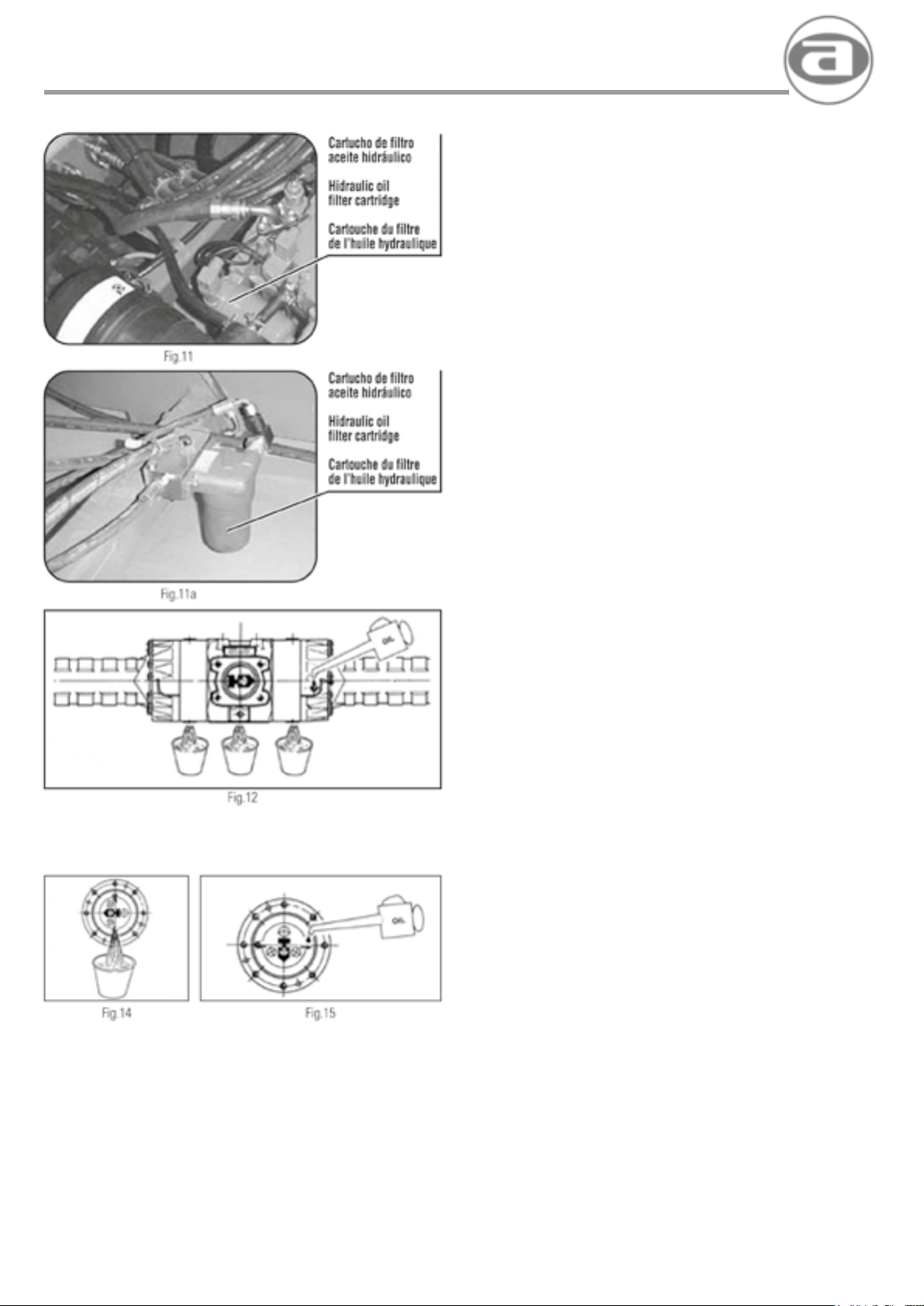
agria hispania, s.l.
MANTENIMIENTO
DESPUES DE LAS PRIMERAS 100 HORAS DE TRABAJO
1) Realizar el mantenimiento del motor de acuerdo con su manual
de mantenimiento.
2) Limpiar el ltro del aire (Fig. 8) antes de soltar la tapa TP,
presionar la válvula para sacar el polvo acumulado. Desmontar
la tapa TP y sacar los ltros y limpiarlos con aire a presión
(Fig. 9). limpiar el interior del cuerpo del ltro y todo el exterior.
Cada 5 limpiezas SUSTITUIR los elementos ltrantes.
Al realizar el montaje asegurarse del correcto encaje de la tapa TP.
NOTA: Para acceder al ltro, es necesario desmontar la tapa de la
pesa.
3) Comprobar el nivel del líquido de frenos.
4) Comprobar el nivel del aceite hidráulico mediante la varilla
de nivel.
5) Sustituir el cartucho ltrante del aceite hidráulico. este cartucho
está jado en el lateral izquierdo de la bomba principal. Soltar
el cartucho, limpiar la cara del asiento de soporte del cartucho
y lubricarlo con aceite limpio. Montar el nuevo cartucho
apretándolo fuertemente con la mano.
NOTA: Después de cambiar el cartucho del ltro, arrancar el motor
y controlar si existen fugas de aceite. Controlar el nivel del aceite
y si fuera necesario reponerlo.
6) Sustituir el aceite de los grupos diferenciales. Para ello, soltar
los tapones inferiores y recoger el aceite en recipientes
adecuados. llenar con nuevo aceite hasta el nivel (Fig. 12).
7) Sustituir el aceite de los reductores de rueda. Para ello, situar
la reductora en posición, según Fig. 14 y soltar el tapón, recoger
el aceite en un recipiente adecuado. Girar la reductora para
situarla en la posición indicada en Fig. 15 y llenar con aceite nuevo
hasta el nivel.
8) Revisar el estado de la batería, si el nivel del electrolito está bajo,
añadir UNICAMENTE agua destilada.
9) Engrasar todas las partes de lubricación de la máquina, indicados
en la siguiente relación de puntos de engrase.
32
Page 33

agria hispania, s.l.
MAINTENANCE ENTRETIEN
AFTER THE FIRST 100 HOURS OF OPERATION
1) Perform engine maintenance according to the maintenance
manual. Special attention must be given toair lter maintenance.
29 Clean the air lter (Fig.8). Befare releasing the cover TP, press
the valve to take out the accumulated dust. Remove the cover
TP and take out the lters.and clean them with compressed
air (Fig.9).Clean the inside of the body of the lter elements. When
assembling,ensure the correct tting of the cover TP.
NOTE: To access the lter. is necessal’f to remove lile
covercounter weight
3) Check brak.e uid level.
4) Check hydraulic oillevel using the level rod.
5) Replace the hydraulic oil lter cartridge is xed at the left lateral
side of the hydraulic pump (Fig.11). Ralease the cartridge,
clean the surface of the seat of the support of the cartridge
and grease it with clean oil. Put the new cartridge, tightening it
strongly with the hand
.
NOTE: After changing the lter cartridge, start the engine and
check if there are overows of oil. Check the level of the oil and, if
it is necessary replenish it.
6) Replace the oil of the differential groups. To do it, release the lower
covers and keep the oil into adecuate containers. Fill with new oil
until the level Fig.12.
7) Replace the oil of the wheel reductor.To do it, place the reductor
in position as in Fig.14 and ralease the cover. Keep the oil
into an adecuate container. Turn the reductor until placing it in
the indicated position in Fig.15 and ll with new oil. until the level.
8) Check the battery condition. lf the level of the electrolyte level is
low add ONLY distilled water.
9) Grease all the greasing points of the machina indicated in the
following list of greasing points:
APRES LES PREMIERES 100 HEURES DE TRAVAIL
1) Réaliser l’entretien du moteur.conformément au manuel
d’entretien.Accorder une attention spéciale á l’entretien du
ltre d’air.
2) Nettoyer le ltre ll air (Fig. 8) avant de lacher la couvercle TP.
presser la valve pour enlever le poussil!re accumulé,demonter
la couvercle TP. lacher les ltres et nettoyer les ltres avec de
l’air á pression (Fig. 9).Nettoyer l’interieur du corps du ltre
et tout l’extirieur subsistuer les elements ltrantes chaque 5
nettoyages. Il faut s’assurer la carrete emboitement de la couvercle
TP dans le montage
NOTE: Pour accéder au ltre, il est nècessaire de dèmonter le
couvercle du contre-pas
3) Vérier le niveau du liquide de freins.
4) Vérier le niveau d’huile hydraulique au moyen de la tige
de niveau.
5) Substituer la cartouche du ltre de l’huile hydraulique. La
cartouche est place dans la partie laterale gauche du pompe
hydraulique (Fig.11). lacher la cartouche nettoyer le bassement
du support et lubrier avec de l’huile prope. Monter la nouvelle
cartouche en pressant fortement avec la main.
NOTE: Aprés audir change la cartouche du ltre, demarrerle
moteur et verier que n’existent remelre si necessaire.
6) Remplacer l’huile des groupes differentiels. Lacher les bouchons
inferieures et reprendre l’huile dans un recipient adéquat. Remplir
avec d’huile nouveau jusqu’âu niveau Fig.12.
7) Substituer l’huile des reducteurs de roue: Placer le reducteur en
position selon Fig 14,et lacher le bouchon et reprendre l’huile
dans un récipient adéquat.Tourner le reducteur pour qu’il soir
placé dans la position indiqueé dans la Fig. 15 et remplir jusqu’au
niveau avec d’huile nouveau.
8) Reviser l’état de la batterie.si le niveau de l’électrolyte est bas.
ajouter seulement de l’eau distillant.
9) Graisser toutes les parties de lubrication de la machine indiqués
dans la suivante relation des points de graissage.
33
Page 34
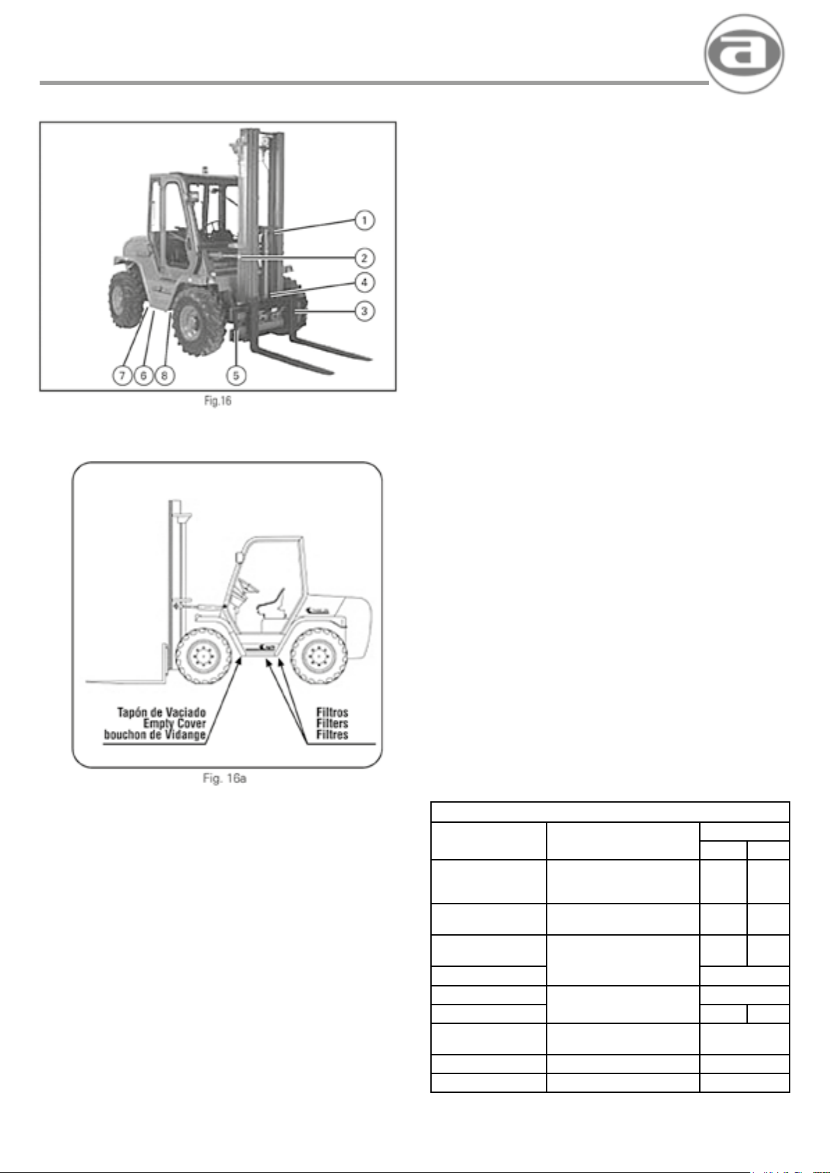
agria hispania, s.l.
MANTENIMIENTO
PUNTOS DE ENGRASE (Fig. 16)
1) Cadenas de mástil.
2) Bulón de inclinación.
3) Guías de carro.
4) Rodillos de mástil.
5) Bulón de giro de mástil.
6) Cojinetes giro del puente.
7) Articulación de rueda.
8) Engrasadores del cardán.
9) Mandos del mástil.
CADA 1500 HORAS DE TRABAJO
1) Realizar el mantenimiento del motor, de acuerdo a su manual de
mantenimiento.
2) Limipiar el ltro del aire y sustituir los elementos ltrantes.
3) Sustituir el aceite de los puentes diferenciales y reductores de
rueda siguiendo las instrucciones del apartado anterior.
4) Sustituir el aceite del circuito hidráulico y los ltros. Para ello
operar de la siguiente manera:
a) Con la transmisión caliente, situar la máquina sobre una
supercie horizontal.
b) Soltar el tapón del vaciado del depósito y vaciar todo el
aceite recogiéndolo en un recipiente con la capacidad
adecuada (Fig. 16 a).
c) Soltar las bridas de aspiración y desmontar los ltros
(Fig. 16 a). Colocar nuevos ltros. Limpiar las supercies
de contacto de las bridas y aplicar pasta de juntas loctite 574
ó similar y amarrar las bridas.
5) Sustituir el cartucho del ltro del motor hidráulico, siguiendo las
indicaciones anteriores de este manual (Fig. 11).
6) Reponer aceite nuevo, de acuerdo a la tabla de lubricación hasta
alcanzar el nivel en el visor.
7) Controlar fugas de aceite en el circuíto hidráulico y si es necesario
sustituir las tuberías ó juntas que tengan fugas.
8) Limpiar y engrasar todas las partes indicadas como puntos de
engrase (Fig. 16).
TABLA DE LUBRICACIÓN
CONCEPTO
Motor
Diferencial
Trasero con Freno
Diferencial
Delantero
Caja Reductora
Reductora Delantera
Reductora Trasera
Circuito Hidráulico
Circuito Frenos
Engrase
API CD-SF/API CE-SF
MIL-L-2104D7MIL-L2104E
Aceite Mineral ATF-Dextron II
Grasa de lilio (VERKOL RS-2)
TIPO CANTIDAD
2 RM 4 RM
SAE 30 Serie III
85 W / 90 LS - 5,8 L
85 W / 90 LS
85 W / 90 LS
Aceite Hidráulico
Drop HV 46
10,5 L 10,5 L
5 L 5,8 L
2,2 L
1 L
Grasa 1 L
60 L
0,25 L
-
34
Page 35

agria hispania, s.l.
MAINTENANCE ENTRETIEN
GREASING POINTS (Fig. 16)
1) Mast chains
2) Tilting bolt
3) Carriage guides
4) Mast rollers
5) Mast rotation bolt
6) Bridge rotating bushings
7) Wheel articulation
B) Cardan greasers
9) Mast commands
EVERY 1500 HOURS OF OPERATION
1) Perform engine maintenance according to the maintenance
manual.
2) Clean the air lter and replace the ltering elements.
3) Replace the oil of the differential axles and wheel
reductors, following the indication of the previous section.
4) Replace the hydraulic circuit oil and the lters. Todo it operate as
follows:
a) With the transmission hot, putthe machina over a horizontal
surface.
b) Ralease the deposit empty cover and empty all the oit
c) Release the intake bridles and remove the lters (Fig.16a).
loctite 574 joints pastor similar and fasten the bridles.
keeping it into a container with the adecuate capacity (Fig.16a)
Put new lter. Clean the bridle contact surfaces and aplicate
POINTS DE GRAISSAGE (Fig. 16)
1) Chaines du mat
2) Boulon d’inclinaison
3) Guides du chariot
4) Rouleaux du mat
5) Boulon de rotation du mat
6) Coussinets de rotation du pont
7) Articulation des roues
8) Graisseurs du cardan
9) Commandes du mat
TOUTES LES 1500 HEURES DE TRAVAIL
1) Réaliser l’entretien du moteur, conformémentvotre Manuel
d’entretien.
2) Nettoyer le ltre d’air et remplacer des elements ltrantes.
3) Subsistuer l’huile des ponts differentiels et reducteurs de roue, en
suivant les indications precités.
4) Subsistuer l’huile du circuit hydraulique et les ltres en suivant ces
indications:
a) avec la transmission chaude.placer la machina sur une
surface horizontele.
b) Lacher le bouchon de vidange du reservoir.vider toute l’huile
et reprendre l’huile dans un recipient adequat (Fig. 16a).
c) Lacher les brides d’aspiration et demonter les ltres
(Fig.16a). Placer les nouveaux ltres. Nettoyer les surfaces
de contact desbrides et appliquer pllte de joints loctite 574 ou
similaire et attacher les brides.
5) Replace the lter cartridge of the hydraulic engine, following
the previous indications ofthis manual (Fig. 11).
6) Replace with new oil,according with the greasing table until
reaching the level of the viewnder
7) Check overows of oil of the hydraulic circuit and, if it is necessary,
replace the hosepipes or joints with overows.
B) Clean and grease all the parts indicated as greasing points
(Fig. 16).
LUBRICATION TABLE
CONCEPT TIPE
Engine
Rear Differential
Front Differential
Reductor Box
Front Wheel Reduc.
Rear Wheel Reduc.
Hidraulic Oil
Brake Fluid
Greassing
API CD-SF/API CE-SF
MIL-L-2104D7MIL-L2104E
Mineral oil ATF-Dextron II
Lilio grease (VERKOL RS-2)
SAE 30 Serie III
85 W / 90 LS - 5,8 L
85 W / 90 LS
85 W / 90 LS
Hidráulic oil
Drop HV 46
QUANTITE
2 RM 4 RM
10,5 L 10,5 L
5 L 5,8 L
2,2 L
1 L
Grease
1 L
60 L
0,25 L
-
5) Subsistuer la cartuche du ltre du moteur hydraulique en suivant
les indications precités (Fig. 11).
6) Remplir d’huile nouveau d’accord avec le tableau de lubrication
jusqu’au moment que l’huile attendre le niveau du viseur.
7) Contrôle des fuites d’huile dans le circuit hydraulique et si
nécessaire, remplacer les tuyaux ou les joints qui fuient.
8) Nettoyer et graisser tous les parties indiquees cllme points de
graissage (Fig. 16).
LUBRICATION TABLE
CONCEPT TYPE
SAE 30 Serie III
Moteur
Differentiel arriere
Differentiel avant
Reducteurs
Reduc. roue avant
Reduc. roue arriere Graiss 1 L
Huille hydraulique
liquide de freins
Graissage
API CD-SF/API CE-SF
MIL-L-2104D7MIL-L2104E
85 W / 90 LS - 5,8 L
85 W / 90 LS
85 W / 90 LS
Huile hydraulique
Drop HV 46
Huile Minerale ATF-Dextron II
Graiss de lilio (VERKOL RS-2)
QUANTITE
2 RM 4 RM
10,5 L 10,5 L
5 L 5,8 L
2,2 L
1 L
60 L
0,25 L
-
35
Page 36
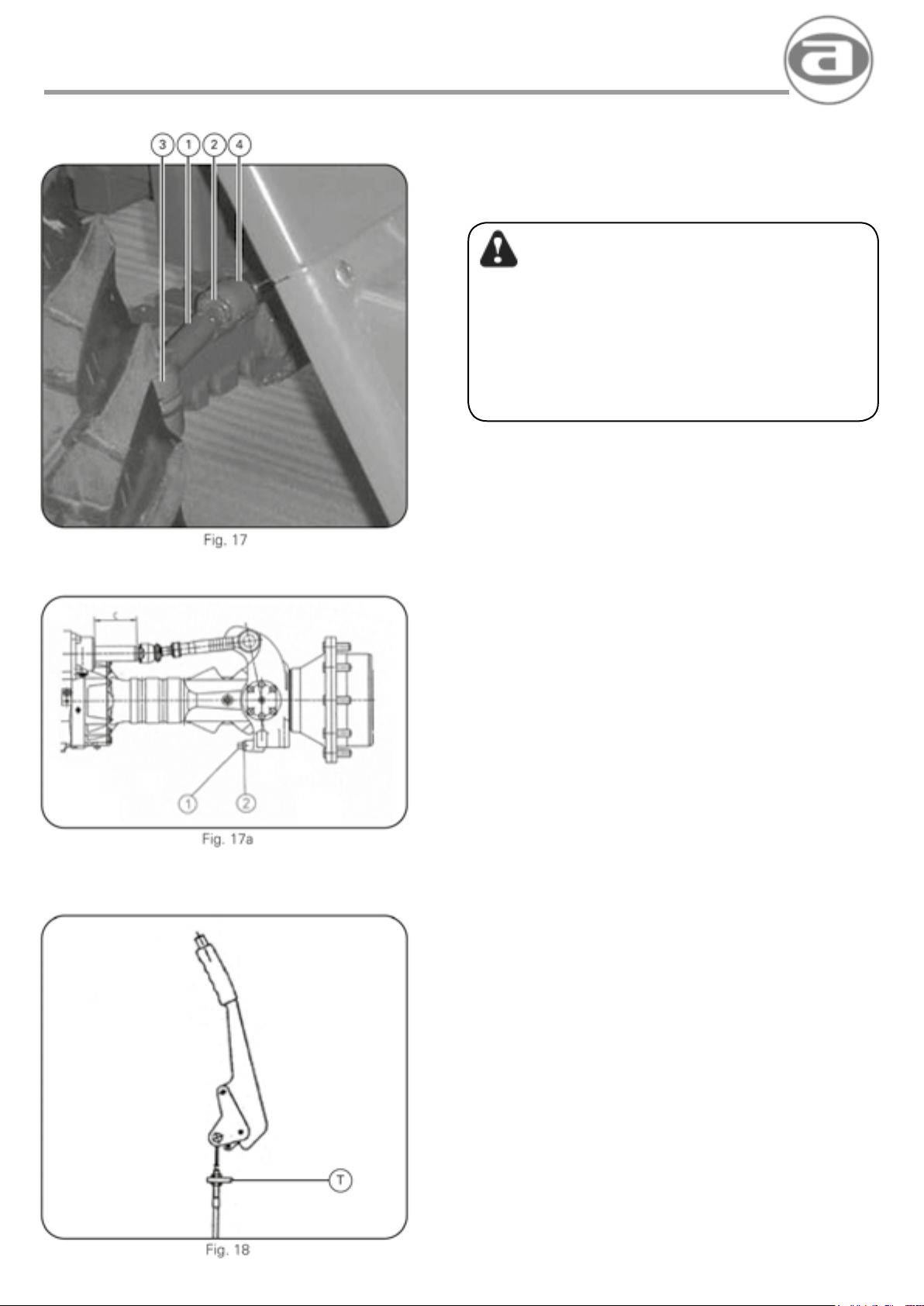
agria hispania, s.l.
MANTENIMIENTO
REGULACIONES PERIODICAS
ATENCION
LA DIRECCIÓN, LOS FRENOS, LOS DISPOSITIVOS DE
SEÑALIZACIÓN Y LAS PROTECCIONES, SON ELEMENTOS
ESENCIALES DE SEGURIDAD, EN TODO MOMENTO DEBEN
ESTAR EN PERFECTO ESTADO DE REGULACION.
SI SE OBSERVAN DETERIOREOS O DESGASTES EN ALGUNO
DE ESTOS ELEMENTOS O SUS PARTES, HAY QUE DETENER DE
INMEDIATO LA MAQUINA Y PROCEDER A SU SUSTITUCIÓN POR
UN SERVICIO AUTORIZADO.
1) DIRECCIÓN (Fig. 17)
Mediante la barra (1) se puede regular la alineación de las ruedas
traseras. Asegurarse que las tuercas (2) y (3), estén bien apretadas.
IMPORTANTE: Si se observa holgura en la rótula (4) o el fuelle de
goma está roto, SUSTITUIR la rótula.
1a)
REGULACIÓN DEL ANGULO DE GIRO DE LAS RUEDAS (Fig. 17a)
1. Aojar la tuerca 2
2. Regular la longitud del espárrago 1 hasta obtener una carrera
máxima del cilindro de C = 118 mm.
3. Apretar fuertemente la tuerca 2
NOTA: Realizar la misma operación en ambas ruedas.
2) FRENO DE ESTACIONAMIENTO (Fig. 18)
Ajustar el recorrido del mando del freno de estacionamiento, mediante
en tensor (Fig. 18). La palanca del freno de estacionamiento debe
bloquear los frenos a la mitad de su carrera total.
3) ELEMENTOS DE SEÑALIZACIÓN
• Comprobar periódicamente que las luces y pilotos funcionan
correctamente.
• Asegurarse de que el avisador de marcha atrás funciona
adecuadamente, en caso contrario REVISAR los elementos y si
fuera necesario SUSTITUIRLOS.
• Asegurarse de que el motor NO ARRANCA mientras no se situe
la palanca del inversor en su posición neutral, en caso contrario
REVISAR el sistema y si fuera necesario SUSTITUIR los
elementos.
• Asegurarse de que TODAS las protecciones se encuentran
en buen estado de conservación y perfectamente aseguradas en
su posición.
• Observar si existen grietas o suras en el bastidor y en la
estructura de protección. En caso armativo, acudir al Servicio
Ocial y NO TRABAJAR con la carretilla hasta corregir los
desperfectos observados.
36
Page 37
agria hispania, s.l.
MAINTENANCE ENTRETIEN
PERIODIC ADJUSTMENTS
ATTENTION
ALL STEERING, BRAKE, SIGNALLING AND PROTECTIVE
COMPONENTS ARE ESSENTIAL SAFETY ELEMENTS. THEY MUST
BE IN PERFECT CONDITION AND PROPERLY ADJUSTED AT ALL
TIMES.
IF DAMAGE OR WEAR IS EVIDENT IN ANY OF THESE ELEMENTS
OR PARTS THERE OF,STOPTHE ENGINE IMMEDIATELY AND HAVE
THEM REPLACED BY AN AUTHORISED TECHNICAL SERVICE
1) STEERING (Fig. 17)
The rear wheels may be aligned by means of the bar (1). Make
sure that the nuts (2) and (3) are properly tightened at all times.
IMPORTANT: lf wear is evident in hinge joint (4) or if the rubber bellows
is tom, REPLACE the hinge joint.
1a)
ADJUSTMENT OF STEERING LOCK OF THE WHEELS (Fig. 17a)
1. Release nut 2
2. Adjust the length of the stud 1. in arder to obtain a max. stroke of
the Cylinder of C = 118 mm.
3. Tighten strongly the nut 2
NOTE: Make the same operation in botll wheels.
REGLAJES PERIODIQUES
ATTENTION
LA DIRECTION, LES FREINS, LES DISPOSI11FS DE
SIGNALISATION ET LES PROTECTIDNS SONT DES ELEMENTS
ESSENTIELS DE SECURITE, ILS DOIVENT ETRE A TOUT MOMENT
EN PARFAIT ETAT ET PARFAITEMENT REGLES
SI DES DETERIORATlONS OU DES USURES SONT OBSERVEES
DANS CERTAINS DE CES ELEMENTS O DANS LEURS PARTIES,IL
FAUT ARRETER IMMEDIATEMENT lA MACHINE ET PROCEDER A
LEUR REMPlACEMENT PAR UN SERVICE AGREE
1) DIRECTION (Fig. 17)
Au moyen de la barre (1) on peut régler l”alignement des roues arriare.
S’assurer que les écrous (2) et (3) sont toujours bien serrés.
IMPORTANT: Sion observe un jeu dans la rotule
1a)
RÉGLAJE DE L’ANGLE DE VIREMENT DES ROUES (Fig. 17a)
1. Desserrer l’ecrou 2
2. Regler la longueur du goujon 1 jusq’a obtenir une course max.
du Cylindre de C = 118 mm.
3. Serrer fortement l’ecrou 2
NOTE: Faire la même operation dans les deux roues.
2) PARKING BRAKE (Fig. 18)
Adjust the stroke of the parking brake lever through the turnbuckle
T (Fig. 18). The parking brake lever is required to block the brakes
halfway along their full run.
3) ELEMENTS OF SIGNALLING
• Periodically check the lights and panellights for correct operation.
• Ensure that the reverse speed signal is working properly, lf
necessary, CHECK components and REPLACE them.
• Ensure that engine DOES NOT START the inversor lever is not
in neutral position. In contrary case CHECK the System and, if
necessary, REPLACE the elements.
• Ensure that Allprotections are in good condition. perfectly attached
and in place.
• Check for cracks and ssures in the chassis and protection
structure. lf such defects are evident. call for ofcial technical
assistance and DO NOT OPERATE the fork lifter until corrected.
2) FREIN DE STATIONNEMENT (Fig. 18)
Ajustar la commande du frein de stationnement. Parmi le tenteur T
(Fig. 1B) le levier du frein de stationnement doit bloquer les freins a
partir de la moitié de son parcours total.
3) ELEMENTS DE SIGNALISATION
• Vérier périodiquement que les lumillres et les pilotes fonctionnent
correctement.
• S’assurer que l’avertisseur de marche arrire fonctionne de
façon contraire REVISER les éléments et si c’est nécessaire LES
REMPLACER.
• Assurer que le moteur ne démarre pas pendant que la levier de
l’inverseur ne soit pas place en position point mort,en cas contraire
vérier le systeme et si est necessaire changer les elements.
• S’assurer que TOUTES les protections se trouvent en bon état de
conservation et parfaitement assurées dans leur position.
• Observer s’il existe des crevasses ou des ssures dans le chassis
et dans la structure de protection.
En cas afrrnatif. faire appelau Service Ofciel et NE PAS
TRAVAILLER avec le chariot jusqu’i’l ce que les défauts
observés soient corrigés.
37
Page 38

agria hispania, s.l.
MANTENIMIENTO
CIRCUITO HIDRÁULICO
El circuito hidráulico lleva incorporados 4 puntos de control de presión,
con racores Minimex de M 16 x 2 (Fig. 19).
Puntos 1 y 2 (Bomba principal):
Máxima presión de 400 bar.
Punto 3 (Bomba auxiliar):
Presión Mástil: 160 bar..
Presión dirección: 110 bar..
Punto 4 (Bomba de alimentación):
Presión para conexión 4 x 4: 25 bar..
ATENCION
• ANTES DE INTERVENIR EN CUALQUIER COMPONENTE
DE LA INSTALACION ELECTRICA HAY QUE DESCONECTAR
EL CABLE DE MASA DE LA BATERIA.
• NO RECARGAR LA BATERIA EN PRESENCIA DE LLAMAS
LIBRES O EN AMBIENTES CERRADOS, LA VENTILACIÓN
TIENE QUE SER ADECUADA PARA EVITAR EXPLOSIONES
ACCIDENTALES.
• CONECTAR SIEMPRE LOS CABLES AL POLO EXACTO
(POSITIVO CON POSITIVO Y NEGATIVO CON NEGATIVO).
• EVITAR CIRCUITAR LOS BORNES.
• ANTES DE CONTROLAR, LLENAR O RECARGAR LA BATERIA
HAY QUE APAGAR CUALQUIER TIPO DE LLAMA LIBRE (NO
FUMAR).
• CUANDO SE TRABAJE MUY CERCA DE LA BATERIA, HAY
QUE PROTEGERSE CONTRA EVENTUALES SALPICADURAS
DE SOLUCIÓN ACIDA. SI DICHA SOLUCION CAE SOBRE
LA PIEL LAVAR CON AGUA ABUNDANTE Y SI SE PRODUCEN
IRRITACIONES, CONSULTAR A UN MEDICO.
• DURANTE LAS OPERACIONES DE RECARGA, QUITAR LOS
TAPONES DE LOS ELEMENTOS.
La máquina se entrega con una batería que no necesita
mantenimiento. Siempre que se produzca una disminución del nivel
del líquido, la causa tiene que buscarse en la instalación eléctrica; una
vez encontrada, hay que restablecer el nivel utilizando exclusivamente
agua destilada o desmineralizada.
Cuando la batería de la máquina esté parcialmente descargada y,
para la puesta en marcha del motor, sea necesario utilizar una batería
auxiliar, ésta última se tiene que conectar a la batería de la máquina,
conectando los terminales del MISMO SIGNO (positivo con positivo y
negativo con negativo). Esto vale también para recargar la batería con
medios externos.
CAJA DE FUSIBLES
Revisar periódicamente el estado de las conexiones eléctricas y
fusibles. En caso de sustitución MONTAR FUSIBLES DEL MISMO
CALIBRE, de acuerdo al esquema siguiente: (Fig. 20)
1.- Luz posición derecha 7,5 A
2.- Luz posición izquierda
Iluminación del cuadro 7,5 A
3.- Luz corta derecha 7,5 A
4.- Luz corta izda. y control 7,5 A
5.- Luz larga derecha 7,5 A
6.- Luz larga izquierda 7,5 A
7.- Electroválvula inversor 15 A
8.- Electroválvula 4 RM 7,5 A
9.- Libre, predispuesto 15 A
10.- Alimentación de cuadro 15 A
11.- Girofaro, intermitentes 15 A
12.- Emergencia 25 A
38
Page 39
agria hispania, s.l.
MAINTENANCE ENTRETIEN
HYDRAULIC CIRCUIT
The circuit with 4- point hydraulic pressure control incorporated,with
ttings Minimex M 16x2 (Fig. 19).
Points 1 and 2 (Main Pump):
Max.pressure 400 bar
Point 3 (Auxiliary pump):
Max. pressure: 180 bar
Steering pressure: 110 bar
Point 4 (Feeding Pump):
Connection 4 x 4: Pressure 25 bar
ATTENTION
• BEFORE HANDLING ANY ELECTRIC INSTALLATION
COMPONENT, DISCONNECT THE BATTERY’S GROUND
CONNECTION TERMINAL.
• DO NOT CHARGE THE BATTERY NEAR AN OPEN FLAME
SOURCE OR IN A CLOSED ENVIRONMENT, PROVIDE
PROPER VENTILATION IN ORDER TO AVOID ACCIDENTAL
EXPLOSIONS.
• ALWAYS CONNECT THE CABLES TO THE CORRECT
TERMINAL (POSITIVE TO POSITIVE AND NEGATIVE TO
NEGATIVE).
• AVOID SHORT CIRCUITS BETWEENTHE BATTERY TERMINAlS
BEFORE CHECKING,FIWNG DR RECHARGING THE BATTERY.
EXTINGUISH ALL TYPES OF NEARBY OPEN RAMES, DO NOT
SMOKE.
• WHEN WORKING CLDSE TU THE BATTERY. WATCH OUT
FOR INADVERTENT ACID SOLUTION SPILLS, IF SPILLED ON
THE SKIN, RINSE WITH ABUNDANT WATER, IN THE EVENT
OF SKIN IRRITATION, SEE A DOCTOR.
• DURING RECHARGING, REMOVE THE BATTERY PLUGS.
CIRCUIT HYDRAULIQUE
Le circuit intégré avec 4 points de contrôle de la pression hydraulique,
avec des raccords Minimex M 16 x 2 (Fig. 19).
Les points 1 et 2 (Pompe principale):
Máx. pression 400 bar.
Point 3 (Pompe auxiliaire):
Pression de Mât: 160 bar..
Pression de direction: 110 bar..
Point 4 (Pompe d’alimentation):
Pression de conexion 4 x 4: 25 bar..
ATTENTION
· AVANT D’INTERVENIR SUR UN COMPOSANT QUELCONQUE
DE L’INSTALLATION ELECTRIOUE, IL FAUT DECONNECTER
LE CABLE DE MASSE DE LA BATTERIE.
• NE PAS RECHARGER LA BATTERIE EN PRESENCE DE
FLAMMES LIBRES OU DANS DES ENCEINTES FERMEES,
LA VENTILATION DOIT ETRE ADEOUATE POUR EVITER DES
EXPLOSIONS ACCIDENTELLES.
• CONNECTER TOUJOURS LES CABLES AUPULE EXACT
(POSITIF AVEC POSITIF ElNEGATIF AVEC NEGATIF).
• EVITER DE COURT-CIRCUITER LES BORNES.
• AVANT DE CONTROLER, DE REMPLIR OU DE RECHARGER
LA BATTERIE, IL FAUT ETEINDRE TOUTE SURTE DE FLAMME
LIBRE - NE PAS FUMER -.
• LORSOUE L’ON TRAVAILLE TRES PRES DE LA BATTERIE, IL
FAUT SE PROTEGER CUNTRE D’EVENTUEUES
ECLABOUSSURES DE SULUTION ACIDE, SI LA DITE
SOLUTION TUMBE SUR LA PEAU, LAVER AVEC DE
L’EAU EN ABUNDANCE ET,SI DES IRRITATIONS SE
PRODUISENT, CONSULTER UN MEDECIN.
• PENDANT LES OPERATIONS DE RECHARGE, RETIRER LES
BOUCHONS DES ELEMENTS.
The machine is delivered with a maintenance-free battery.
In the event of reduced liquid level, search for the cause by checking
the electric installation. After repair, rell to the correct level with distilled
or demineralised water.
When the battery is partially discharged andan auxiliary battery is
used for starting the engine,connect the auxiliary battery through the
terminals of the SAME SIGN (positive to positive and negative to
negative). This is also the case when the battery is being charged using
external means
FUSE BOX
Periodically check the condition of the electric connections and fuses.
lf replaced, INSTALL FUSES OF AN EQUIVALENT SIZE. according to
the following diagram: (Fig. 20)
1.- Position light, right 7,5 A
2.- Position light, left panel
ilumination, 7,5 A
3.- Dipped beam, right 7,5 A
4.-
Dipped beam, left and controls
5.-
Main beam, right and control
6.- Main beam, left 7,5 A
7.- Revers in electrovalve 15 A
8.- Electrovalve 4 RM 7,5 A
9.- Free, pre-assigned 15 A
10.- Feeding of panel 15 A
11.-
7,5 A
7,5 A
Heading turning, intermittents
12.- Emergency 25 A
15 A
La machina est livrée avec une batterie qui ne demande pas
d’entretien.
A chaque fois qu’une diminution du niveau du liquide se produit, il faut
chercher la cause dans l’installation électrique;une fois celle-ci trouvée,
il faut rétablir le niveau en utilisant exclusivement de l’eau distillée ou
déminéralisée.
Lorsque la batterie de la machine est partiellement déchargée et
lorsque,pour la mise en marche du moteur il est nécessaire d’employer
une batterie auxiliaire, cette derniE’lre doit se connecter la batterie
de la machine en connectant les terminaux du MEME SIGNE (positif
avec positif et négatif avec négatif). Ceci est valable également pour
recharger la batterie avec des moyens externas.
BOITE DES FUSIBLES
Reviser périodiquement l’état des connexions électriques et les
fusibles. En cas de remplacement, MONTER DES FUSIBLES DE
MEME CALIBRE ,conformément au schéma suivant: (Fig. 20)
1.-
Lumière de position droite
2.-
Lumière de position gauche
illumination du tableau 7,5 A
3.-
Lumière courte droite
4.-
Lumière courte gauche et contrôles
5.-
Lumière longue droite et contrôle
6.-
Lumière longue gauche
7,5 A
7,5 A
7.- Électrovalve inverseur 15 A
7,5 A
8.- Électrovalve 4 RM 7,5 A
9.- Libre, prédisposé 15 A
10.- Feeder cadre 15 A
11.-
7,5 A
7,5 A
Pharetournant, intermittents
12.- Emergence 25 A
15 A
39
Page 40

agria hispania, s.l.
MANTENIMIENTO
PERIODO DE REPOSO
Cuando la máquina tenga que permanecer inactiva durante varios
meses, es aconsejable adoptar las siguientes precauciones:
1) Vaciar el aceite del motor con la máquina caliente
2) Poner aceite nuevo en el cárter del motor y hacerlo funcionar,
durante aproximadamente un minuto a bajo régimen.
3) Lavar completamente la máquina
4) Lubricar los órganos provistos de engrasador.
5) Llenar el depósito del carburante hasta el nivel máximo.
6) Aparcar la máquina en lugar seco.
7) Quitar la batería y protegerla contra las temperaturas bajas.
Recargarla una vez al mes.
8) Colocar caballetes debajo de los ejes con el n de proteger
los neumáticos.
9) Una vez levantada la máquina, desinar los neumáticos.
ATENCION
• NO USAR GASOLINA U OTROS LIQUIDOS INFLAMABLES EN
LAS OPERACIONES DE LIMPIEZA.
• LLENAR EL DEPOSITO CON EL MOTOR PARADO Y LEJOS DE
CUALQUIER TIPO DE LLAMA LIBRE.
• EVITAR CIRCUITAR LOS BORNES
• PARA LAS OPERACIONES DE RECARGA DE LA BATERIA,
EXTINGUIR CUALQUIER TIPO DE LLAMA LIBRE.
Y PROTEGERSE CONTRA EVENTUALES SALPICADURAS DE
SOLUCION ACIDA.
• LEVANTAR LA MAQUINA CON GATOS ADECUADOS SEGUN
LAS NORMAS CONTRA INFORTUNIOS EN VIGOR.
40
Page 41
agria hispania, s.l.
MAINTENANCE ENTRETIEN
INACTIVE PERIODS
lf the machine is to remain inactiva for several months, the following
precautions are recommended:
1) Drain engine oilwhile hot.
2) Rell the engine sump with new oil, start the engine and keep it
running at slow speed for approximately one minute.
3) Wash the machina thoroughly.
4) Lubricate all components tted with greasing points.
5) Fill the fuel tank to its maximum level.
6) Park the machina in a dry place.
7) Remove the battery and protect it against low temperaturas.
Recharge it once every month.
8) lnstall trestles under the axles in arder to protect the tires.
9) After raising the machine, deate the tires.
ATTENTION
• DO NOT USE GASOLINE OR OTHER INFLAMMABLE LIQUIDS
DURING CLEANING OPERATIONS
• WHEN REFUELLING, STOP THE ENGINE ANO KEEP AWAY
FROM ANY TYPE OF FREE FLAME
PERIODE DE REPOS
Lorsque la machine doit raster inactiva pendant plusieurs mois, il est
conseillé d’adopter les précautions suivantes:
1) Vider l’huile du moteur avec la machine à chaud.
2) Mettre de l’huile neuve dans le carter du moteur et le faire
fonctionner, pendant enviren une minute,abas régime.
3) Laver compllltement la machine.
4) Lubrier les éléments prévus de graissage.
5) Remplir le réservoir de carburant jusqu’au niveau maximum.
6) Garer la machine dans un endroit sec.
7) Retirer la batterie et la protéger centre les basses températures.
La recharger une fois par mois.
8) Placer des chevalets sous les axes an de protéger les pneus.
9) Une fois la machine soulevée, dégoner les pneus.
ATTENTION
• NE PAS UTILISER D’ESSENCE OU D’AUTRES PRODUITS
INFLAMMABLES DANS LES OPERATIONS DE NETTOYAGE.
• REMPLIR LE RESERVOIR AVEC LE MOTEUR ARRETEETLOIN
DETOUTE SORTE DE FLAMME LIBRE.
• AVOID SHORT CIRCUITS IN THE BATTERY TERMINALS
• WHEN RECHARGING THE BATTERY, EXTINGUISH ALL
NEARBY FREE FLAMES ANO PROTECT YOURSELF AGAINST
ACID SOWTION SPILLAGE
• RAISE THE MACHINE USING AN ADEOUATE JACK,
IN COMPLIANCE WITH SAFETY REGULATIONS.
• EVITER DE COURT-CIRCUITER LES BORNES.
• POUR LES OPERATION DE RECHARGE DE LA BATTERIE,
ETEINDRE TOUTE SORTE DE FLAMME LIBRE ET SE
PROTEGER CONTRE D’EVENTUELLES ECLABOUSSURES
DE SOLUTION ACIDE.
• LEVER LA MACHINE AVEC DES VERINS ADEQUATS
CONFORMEMENT AUX NORMES CONTRES LES ACCIDENTS
EN VIGUEUR.
41
Page 42

agria hispania, s.l.
PROBLEMAS - CAUSAS
MOTOR - DEUTZ F4L2011
• Problema - CALENTAMIENTO DE MOTOR
• Chivato temperatura encendido
• Causa:
- Radiador Tupido o sucio
- Correa defectuosa
- Insuciente entrada de Aire,
posible obstrucción de los paneles laterales de entrada de aire
• Problema - HUMO NEGRO EXCESIVO
• Causa:
- Filtro de aire sucio y obstruido
- Inyectores sucios
- Bomba de inyección independientes en mal estado
- Gasoil sucio
- Motor frío, calentarlo 5 minutos
• Problema - FALLO EN EL ARRANQUE
• Causa:
- Batería desconectada, bornes ojos u oxidados
- Batería sin carga
- Fusibles fundidos
- Motor de arranque averiado
- Bomba inyectora o inyectores defectuosos
- Agua en el gasoil o aire en el circuito
- Sin gasoil o ltro tupido
- Válvula de Pare en mal estado
- Cremallera de Bombas agarrotada
- Tubos de gasoil obstruidos
SISTEMA HIDRAULICO
Problema - TRASLACION DEFECTUOSA O NULA
Causa:
- Bomba Hidrostática defectuosa con baja presión
- Bomba de freno agarrada
- Inching de freno (válvula agarrada en bomba Hidro)
- Válvula DEA defectuosa (porquería, enclavamiento, etc.
en bomba hidro.
- Cable de freno de mano gripado
- Paquete de disco de frenos en puente delantero torcidos
o revirados
- Porquería en bomba Hidro en tapón metálico con válvula
situada debajo de la válvula DEA
- Problema en el mando inversor
- Electro-válvulas de delante y atrás en bomba Hidro
- Fusibles fundidos, corte de corriente en mando inversor
o electro-válvulas
- Aro de arrastre entre motor de explosión y bomba Hidro
- Filtro hidráulico tupido, aceite degradado
- Aire en el circuito
- Bajo nivel de aceite en depósito
- Motor Hidrostático con baja potencia
42
Page 43

agria hispania, s.l.
PROBLEMS - CAUSES PROBLÈMES - CAUSES
ENGINE - DEUTZ F4L2011
• Problem - OVERHEATING OF THE ENGINE
• Signal in the Panel swiched on
• Cause:
- Defective Radiator
- Defective or Loose Belt
- Insufent Air inlet due to dirtiness in the lateral panel of the hood
• Problem - EXCESIVE BLACK SMOKE
• Cause:
- Dirt in the Air Filter or Obstructed
- Dirty Inyectors
- Independent Injection Pump or pumps damaged
- Dirty Gasoil
- Cold Engine. Preheat of 5 minutes
• Problem - START OF THE MACHINE
• Cause:
- Disconnected Battery, loose or rusty terminals
- Uncharged Battery
- Molten fuses
- Starter engine damaged
- Injection pump or injector damaged
- Water in the Gasoil or Air in the circuit
- No Gasoil or Gas Filter blocked or to dense
- Stop Valve defective
- Pump Zipper blocked
- Gasoil hoses blocked
MOTOR- DEUTZ F4L2011
• Problema - CALENTAMIENTO DE MOTOR
• Chivato temperatura encendido
• Causa:
- Radiador Tupido o sucio
- Correa defectuosa
- Insuciente entrada de Aire,
posible obstrucción de los paneles laterales de entrada de aire
• Problema - HUMO NEGRO EXCESIVO
• Causa:
- Filtro de aire sucio y obstruido
- Inyectores sucios
- Bomba de inyección independientes en mal estado
- Gasoil sucio
- Motor frío, calentarlo 5 minutos
• Problema - FALLO EN EL ARRANQUE
• Causa:
- Batería desconectada, bornes ojos u oxidados
- Batería sin carga
- Fusibles fundidos
- Motor de arranque averiado
- Bomba inyectora o inyectores defectuosos
- Agua en el gasoil o aire en el circuito
- Sin gasoil o ltro tupido
- Válvula de Pare en mal estado
- Cremallera de Bombas agarrotada
- Tubos de gasoil obstruidos
HYDRAULIC SYSTEM
• Problem - DEFECTIVE OR NULL TRANSLATION
• Cause:
- Low pressure in the Hydraulic Pump
- Brake pump seized
- Brake inching (Valve seized in Hydro Pump)
- DEA Valve defective (dirtiness, block in Hydro Pump)
- Faulty brake cable drive
- Brake Discs in Front Axle twisted
- Dirtiness in metal tap underneath Hydro pump DEA valve
- Faulty inversor Handle
- Faulty Electro Valve for Front-Rear movement in the Hydro Pump
- Melted Fuses, faulty wiring to the Inversor Handle
or Electro-Valves
- Faulty Drive ring between Diesel Engine and Hydro Pump
- Hydraulic Filter blocked or oil degraded
- Air in the circuit
- Low Oil level in the tank
- Low Power Hydrostatic Motor
SISTEMA HIDRAULICO
Problema - TRASLACION DEFECTUOSA O NULA
Causa:
- Bomba Hidrostática defectuosa con baja presión
- Bomba de freno agarrada
- Inching de freno (válvula agarrada en bomba Hidro)
- Válvula DEA defectuosa (porquería, enclavamiento, etc.
en bomba hidro.
- Cable de freno de mano gripado
- Paquete de disco de frenos en puente delantero torcidos
o revirados
- Porquería en bomba Hidro en tapón metálico con válvula
situada debajo de la válvula DEA
- Problema en el mando inversor
- Electro-válvulas de delante y atrás en bomba Hidro
- Fusibles fundidos, corte de corriente en mando inversor
o electro-válvulas
- Aro de arrastre entre motor de explosión y bomba Hidro
- Filtro hidráulico tupido, aceite degradado
- Aire en el circuito
- Bajo nivel de aceite en depósito
- Motor Hidrostático con baja potencia
43
Page 44

agria hispania, s.l.
PROBLEMAS - CAUSAS
• Problema - TEMPERATURA ACEITE HIDRAULICO
• Causa:
- Radiador sucio o porquería en el panel
- Ventilador o correa defectuosa o oja
- Aceite degradado o ltro sucio obstruido
- Tubos hidráulicos obstruidos
- Equipos hidráulicos dañados (bombas, etc.)
- Bajo nivel de aceite
- Maniobras inadecuadas en el empleo de la maquina
- Aceite espumoso Posible inltración de aire
• Problema - SISTEMA ELEVACION DE MASTIL
• Causa:
- Baja presión del distribuidor taraje 180 BAR
- Filtro deposito sucio Aceite degradado
- Tubería obstruida taponada
- Válvula reguladora para velocidad descenso
- Válvula paracaídas obstruidas
- Carriles de mástil torcidos
- Rodillos de mástil con mucha holgura
- Cilindros de elevación
- Funcionamiento irregular de bomba hidráulica
- Empaquetaduras o guarniciones de goma de los
cilindros elevación
-Cilindros con los vástagos rallados o torcidos
• Problema - DIRECCION HIDRAULICA
• Causa:
- Dirección dura, baja presión en el orbitrol de dirección,
Taraje máximo 120 bar.
- Empaquetadura del cilindro dirección defectuosa. Dirección dura
- Caña de dirección agarrada. Dirección dura
- Puente direccional sin engrase en cuerpos de giro
- Orbitrol defectuoso
PRESIONES DE
LOS ELEMENTOS HIDRAULICOS
- Bomba hidráulica Litros
- Distribuidor 180 BAR
- Orbitrol dirección 120 BAR
- Bomba Hidrostática Alimentación G 25 bar
- Máxima presión MA-MB 400 bar
dispara la válvula de seguridad, el tarado es de 430 bar
• Conexión del 4X4 - 25 a 30 bar
Problema - Si no tenemos presión o la presión es baja en la bomba
Hidro podemos tener el problema en la bomba o en el motor .Para
diferenciar si la avería está en la bomba o en el motor podemos
taponar las dos vías (los dos tubos gordos que van de bomba a motor
y coger la presión en la bomba si la presión es la correcta 400 bar es
que el motor hidro está averiado y si sigue sin dar la presión inferior a
400Ba el problema lo tenemos en la bomba
44
Page 45

agria hispania, s.l.
PROBLEMS - CAUSES PROBLÈMES - CAUSES
• Problem - HYDRAULIC OIL TEMPERATURE
• Cause:
- Dirt in Radiator or in the panel
- Fan or fan belt loose or Defective
- Degraded Oil or Blocked Filter
- Hydraulic Hoses blocked
- Hydraulic Pump or Motor Damaged
- Low Hydraulic Oil Level
- Bad Operation of the machine
- Foamy Oil-Posible entry of Air
• Problem - MAST OPERATION
• Cause:
- Distributor rated less than 180 BAR
- Dirt in Filter or degraded Oil
- Hoses blocked
- Downwards regulation valve defective
- Parachute Valve Blocked
- Mast tracks twisted
- Mast Rollers to loose
- Elevation Cylinders
- Irregular operation of the Hydraulic pump
- Rubber Seal set of Elevation cylinders damaged
- Cylinder Rods schatched or twisted
• Problem - HYDRAULIC STEERING
• Cause:
- Hard steering due to low pressure of the orbitrol, Max. 120 BAR
- Seals of the steering cylinder Defective
- Steering-Reed blocked
- Steering Hub without greasing
- Defective Orbitrol
PRESSURES
OF HYDRAULIC ELEMENTS
-Bomba hidráulica Litros
-Distributor 180BAR
-Orbitrol 120 BAR
-Hydrostatic Pump - inlet - G 25 BAR
-Maximum Presure 400 Bar
activates security valve. Proper regulation 300 BAR
• Conexión del 4X4 - 25 a 30 bar
If there is no pressure or the pressure is low Hydrostatic Motor or
Engine may be damaged. To know witch one is causing the problem
you should put a tap in the main two hoses conecting the Pump to
the Motor. Then take the pressure in the pump. If the pressure is 400
BAR the engine is the fauly one; if the pressure is below 400 BAR the
problem may be located in the pump
• Problema - TEMPERATURA ACEITE HIDRAULICO
• Causa:
- Radiador sucio o porquería en el panel
- Ventilador o correa defectuosa o oja
- Aceite degradado o ltro sucio obstruido
- Tubos hidráulicos obstruidos
- Equipos hidráulicos dañados (bombas, etc.)
- Bajo nivel de aceite
- Maniobras inadecuadas en el empleo de la maquina
- Aceite espumoso Posible inltración de aire
• Problema - SISTEMA ELEVACION DE MASTIL
• Causa:
- Baja presión del distribuidor taraje 180 BAR
- Filtro deposito sucio Aceite degradado
- Tubería obstruida taponada
- Válvula reguladora para velocidad descenso
- Válvula paracaídas obstruidas
- Carriles de mástil torcidos
- Rodillos de mástil con mucha holgura
- Cilindros de elevación
- Funcionamiento irregular de bomba hidráulica
- Empaquetaduras o guarniciones de goma de los
cilindros elevación
-Cilindros con los vástagos rallados o torcidos
• Problema - DIRECCION HIDRAULICA
• Causa:
- Dirección dura, baja presión en el orbitrol de dirección,
Taraje máximo 120 bar.
- Empaquetadura del cilindro dirección defectuosa. Dirección dura
- Caña de dirección agarrada. Dirección dura
- Puente direccional sin engrase en cuerpos de giro
- Orbitrol defectuoso
PRESIONES DE
LOS ELEMENTOS HIDRAULICOS
- Bomba hidráulica Litros
- Distribuidor 180 BAR
- Orbitrol dirección 120 BAR
- Bomba Hidrostática Alimentación G 25 bar
Máxima presión MA-MB 400 bar dispara la válvula de seguridad,
el tarado es de 430 bar
Conexión del 4X4 - 25 a 30 bar
Problema - Si no tenemos presión o la presión es baja en la bomba
Hidro podemos tener el problema en la bomba o en el motor .Para
diferenciar si la avería está en la bomba o en el motor podemos
taponar las dos vías (los dos tubos gordos que van de bomba a motor
y coger la presión en la bomba si la presión es la correcta 400 bar es
que el motor hidro está averiado y si sigue sin dar la presión inferior a
400Ba el problema lo tenemos en la bomba
45
Page 46
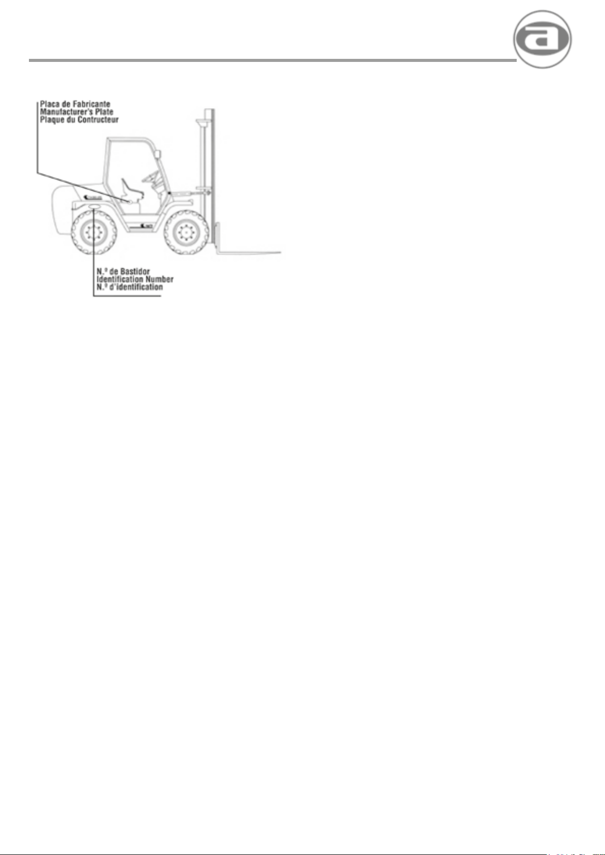
agria hispania, s.l.
AISTENCIA TECNICA
Para resolver cualquier problema de su máquina acuda a un servicio
ocial AGRIA. Utilice siempre repuestos originales AGRIA
IDENTIFICACIÓN DE LA MAQUINA
El número de chasis está grabado en la parte derecha junto a la rueda
trasera.
REPUESTOS
Utilizar exclusivamente REPUESTOS ORIGINALES. Si se utilizan
repuestos no originales, el fabricante declina cualquier responsabilidad
y considera anuladas las condiciones de garantía
• Para pedir los repuestos dirigirse al CONCESIONARIO AUTORIZADO
de la zona. Cuando se soliciten repuestos hay que indicar:
1) N.º de chasis de la máquina
2) Tipo del motor
3) N.º del motor
4) Código del repuesto solicitado
5) Cantidad solicitada.
SERVICIO DE ASISTENCIA
Para la asistencia en las operaciones de revisión o en las reparaciones
que no se pueden llevar a cabo fácilmente con los medios de los cuales
dispone normalmente una presona, el fabricante recomienda dirigirse al
CONCESIONARIO AUTORIZADO de la zona.
También puede dirigirse a:
B.º Euba, s/n • 48340 AMOREBIETA (Bizkaia)
GARANTIA
Todos los fabricados de AGRIA HISPANIA, S.L., están amparados por
la GARANTIA DE UN AÑO, a partir de la fecha de entrega. La garantía
cubre cualquier defecto de material o fabricación en las piezas, y la
concesión está sujeta a las condiciones de garantía establecidas por
AGRIA HISPANIA, S.L..
AGRIA HISPANIA, S.L. Asume la garantía solamente en cuanto a
piezas suministradas por proveedores, la garantía se limita a las
condiciones y al período jados por los mismos. la garantía no cubre la
mano de obra empleada en la sustitución de las piezas.
AGRIA HISPANIA, S.L.
Tel.: 94 630 00 55
Fax: 94 630 01 34
e-mail: [email protected]
EXCLUSIÓN DE LA GARANTÍA
Quedan excluídos los daños que hubieran surgido por mala
manipulación de los fabricados o negligencia en la manutención de la
máquina y las ocasionadas por el transporte.
46
Page 47

agria hispania, s.l.
TECHNICAL ASSISTANCE ASSISTANCE TECHNIQUE
To solve any problem in connection with your machine,see your
AGRIA ofcial service dealer. Always use original AGRIA spare parts.
MACHINE IDENTIFICATION
The chassis number is printed on the right side, adjacent the rear
wheel.
SPARE PARTS
Use only ORIGINAL SPARE PARTS. lf non-original spare parts are
used, the manufacturar declines all responsibility and will annulall
guarantee conditions.
• To obtain spare parts, visit the AUTHORISED DEALER in your area.
When ordering a spare part, indicate:
1) Machine chassis number
2) Type of engine
3) Engine number
4) Spare part code
5) Quantity needed
TECHNICAL ASSISTANCE
For technical assistance in revision or repair tasks which cannot be
readily performed with the means normally available to the operator,the
manufacturar recommends that help be sought from the AUTHORISED
DEALER in the area.
Or, call directly on:
Pour résoudre un probléme quelconque de votre machine, faîtes appel
à un service ofciel AGRIA. Utilisez toujours despieces de rechange
originales AGRIA.
IDENTIFICATION DE LA MACHINE
Le numéro du châssis est gravé sur la partie droite, à côté de la roue
arrière.
PIECES DE RECHANGE
Utiliser exclusivement des PIECES DE RECHANGE ORIGINALES. Si
on utilise des pièces de rechange non originales, le fabricant décline
toute responsabilité et considère les conditions de la garanties annulées.
• Pour demander les pillees de rechange, s’adresser au
CONCESSIONNAIRE AGREE de la zone.
Lorsqu’on commande la pièce de reehange, il faut indiquer:
1) N.º du châssis de la machine.
2) Type de moteur.
3) N.º du moteur.
4) Code de la pièce de reehange demandée.
5) Quantité demandée.
SERVICE D’ASSISTANCE
Pour l’assistance dans les opérations de révision ou dans les
réparations,qui ne peuvent pas se mener a bout facilement avec
les moyens dont dispose normalement une personne, le fabricant
recommande de s’adresser au CONCESSIONNAIRE AGREE de la
zone.
B.º Euba, s/n • 48340 AMOREBIETA (Bizkaia)
AGRIA HISPANIA, S.L.
Tel.: 94 630 00 55
Fax: 94 630 01 34
e-mail: [email protected]
GUARANTEE
All AGRIA HISPANlA S.L. products are GUARANTEED FOR 1 YEAR
as from the date of delivery.The guarantee covers any defect in the
material or fabrication of the parts,based on the guarantee conditions
set forth by Agria Hispania S.L.
AGRIA HISPANlA S.L. only guarantees parts of its own manufacture.
In the case of parts from suppliers,the guarantee is limited to the terms
and conditions set by eaeh supplier. The guarantee does not cover part
replacement labour costs.
GUARANTEE EXCLUSIONS
Any damage resulting from inadequate handling, failure to comply with
maintenance requirements or during transport will not be covered by the
guarantee.
S’adresser également a :
AGRIA HISPANIA, S.L.
B.º Euba, s/n • 48340 AMOREBIETA (Bizkaia)
Tel.: 94 630 00 55
Fax: 94 630 01 34
e-mail: [email protected]
GARANTIE
Tous les produits fabriqués par AGRIA HISPANlA S.L., sont protégés
par une GARANTIE DE 1 ANNÉE á partir de la date de livraison. La
garantie couvre tous les défauts de matériel ou de fabrieation dans les
pillees,et la concession est sujette aux conditions de garantie établies
par AGRIA HISPANIA S.L.
AGRIA HISPANlA S.L. assume la garantie uniquement sur les pieces
livrées par des fournisseurs, la garantiese limite aux conditions et a la
période xées par ceux-ci.La garantie ne couvre pas la main d’oeuvre
employée pour le remplaeement des pillees.
EXCLUSION DE LA GARANTIE
Sont exclus de la garantie les dommages, qui peuvent surgir en raison
d’une mauvaise manipulation des produits fabriqués ou en raison de
la négligenee dans l’entretien de la machina ainsi que les dommages
occasionnés par le transport
47
Page 48
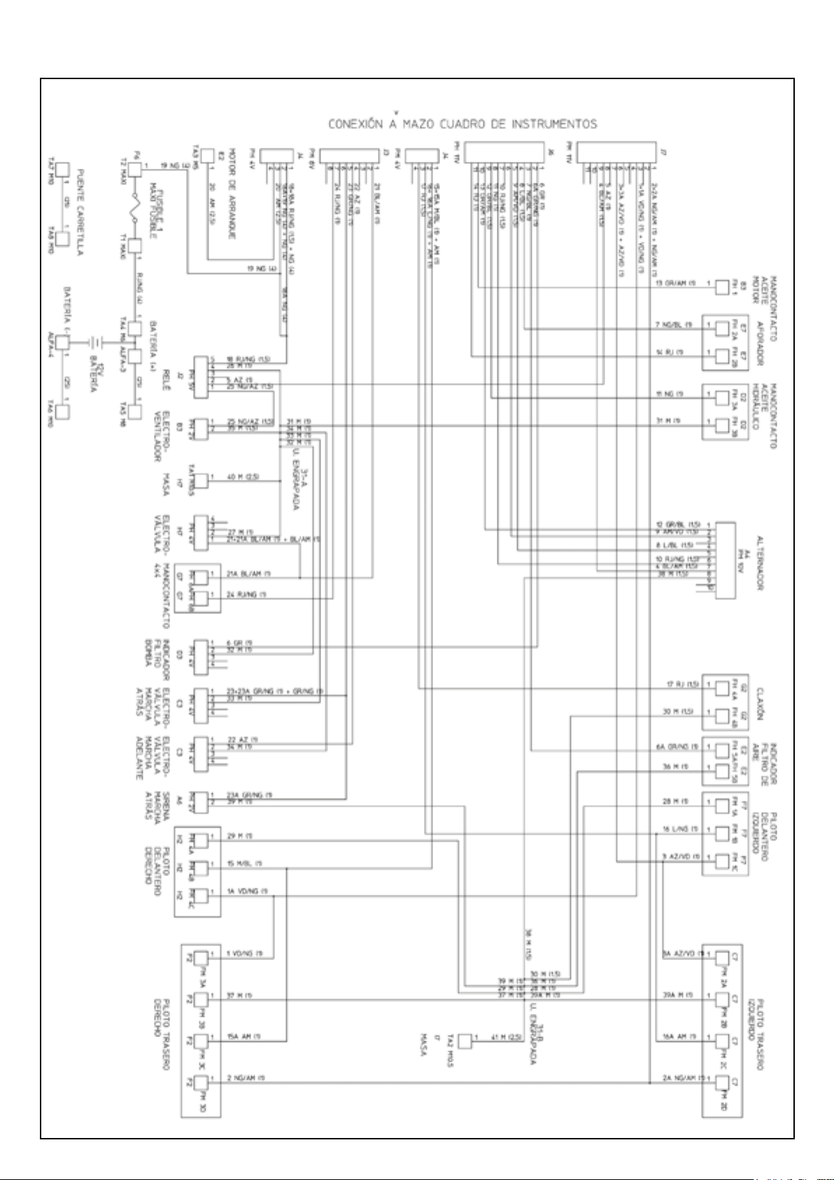
agria hispania, s.l.
ESQUEMA ELÉCTRICO GENERAL • GENERAL ELECTRIC SCHEME
48
Page 49
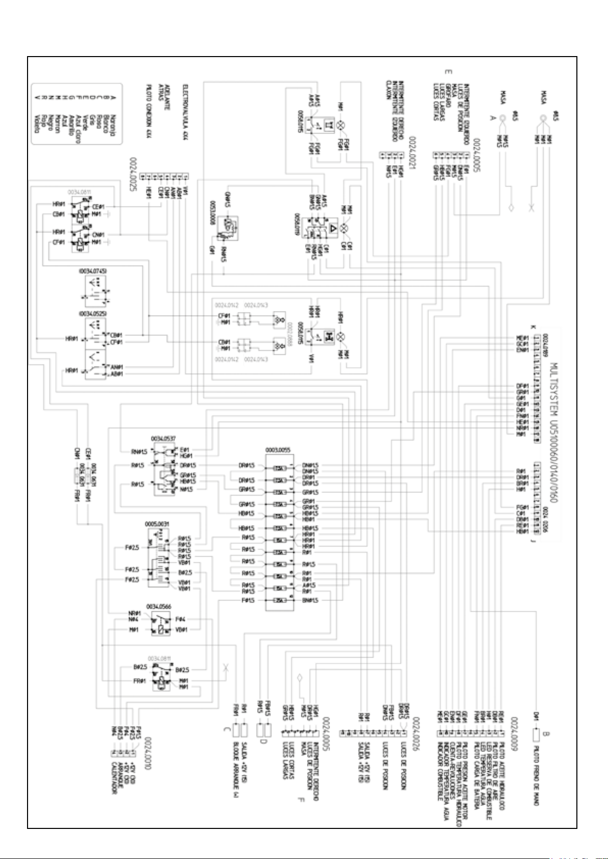
ESQUEMA ELÉCTRICO CUADRO DE MANDOS • DASHBOARD ELECTRIC SCHEME
agria hispania, s.l.
49
Page 50

agria hispania, s.l.
CONTROL DE REVISIONES PERIODICAS
PERIODICAL CHEKINGS • PERIODIQUE REVISION
Modelo / Model / Modele:
Fecha de compra:.......................................................... Concesionario: .......................................................................
Purchase date:............................................................... Dealer: .......................................................................................
Achat date:..................................................................... Concesonaire: ............................................................................
50
Page 51

agria hispania, s.l.
51
Page 52

agria hispania, s.l.
agria hispania, s.l.
Telf.: + 34 94 630 00 55 • Fax: + 34 94 630 01 35
[email protected] • http://www.agria.es
Apartado 26 • Bº Euba, s/n. • 48340 AMOREBIETA (Vizcaya) ESPAÑA
Ref.: 809598
52
 Loading...