

Page 1
Operating Instructions No. 998 720 11.98
Before commissioning the machine, read operating instructions
and observe warnings and safety instructions.
3308, 3307
Operating Instructions
for agria
®
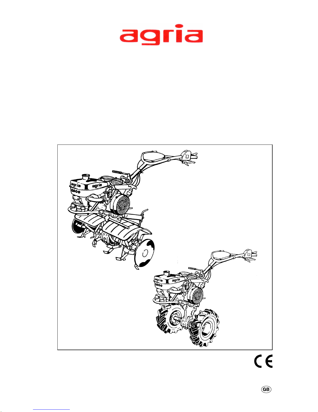
Power Hoe T ype 6000
&
Quality that's your
pleasure!
Horticultural MachineryHorticultural Machinery
Horticultural MachineryHorticultural Machinery
Horticultural Machinery
Page 2
2 Power Hoe 6000 Edition 11.98
Symbols, Name Plate
Please complete:
Machine T ype No.: .........................
ID/Machine No.:
......................................................
Engine T ype: ..................................
Engine No.: ....................................
Date of Purchase: ..........................
For name plate, refer to p5/fig. B/26.
For engine type and number, refer to
p5/item no. 27.
Please state these data when ordering
spare parts to avoid wrong deliveries.
Only use original agria spare parts!
Specifications, figures and dimensions
stated in these instructions are not binding. No claims can be derived from them.
We reserve the right for improvements
without changing these instructions.
This delivery comprises:
l
Operating instructions
l
Power hoe
– basic machine
– steering handle
l
T ool kit
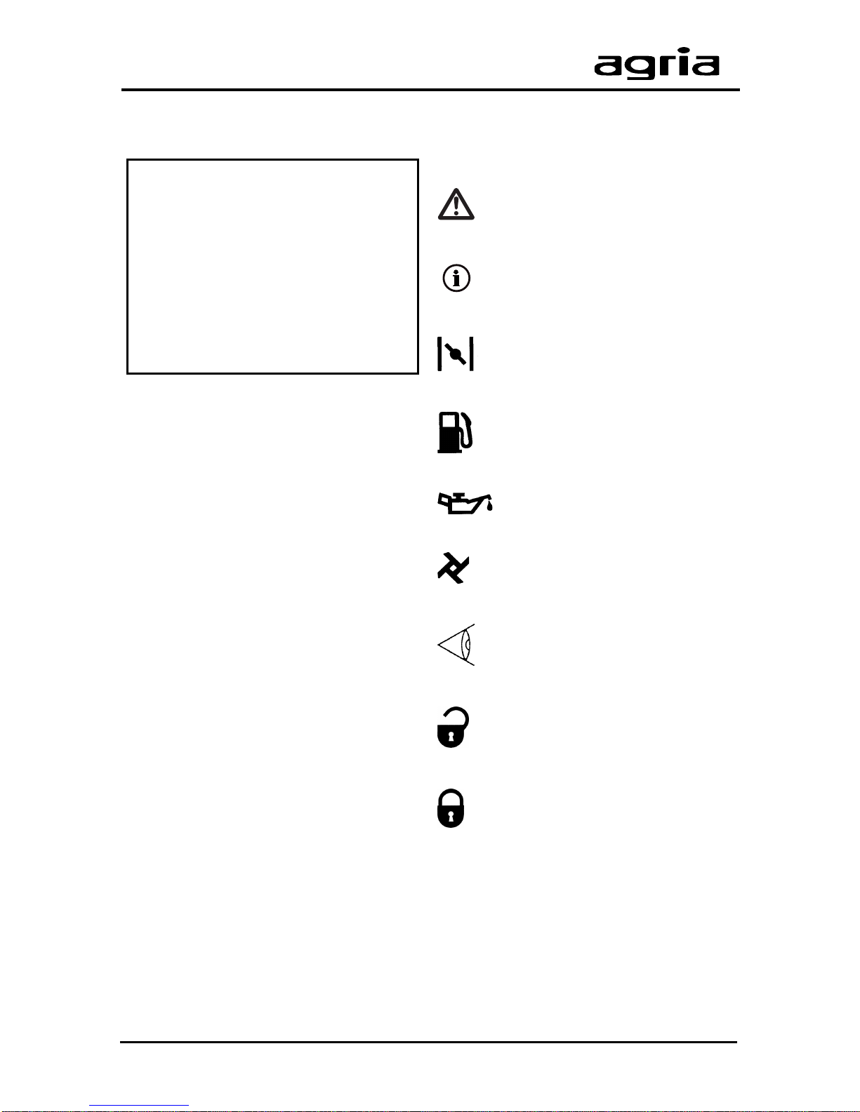
Symbols
Warning – Danger
Important information
Choke
Fuel
Oil
Hoeing/tilling drive
Visual check
Open (unlocked)
Closed (locked)
Page 3
Edition 11.98 Power Hoe 6000 3
Designation of Parts
Figure A
Figure B
27
Page 4

4 Power Hoe 6000 Edition 11.98
Designation of Parts
Figures A and B
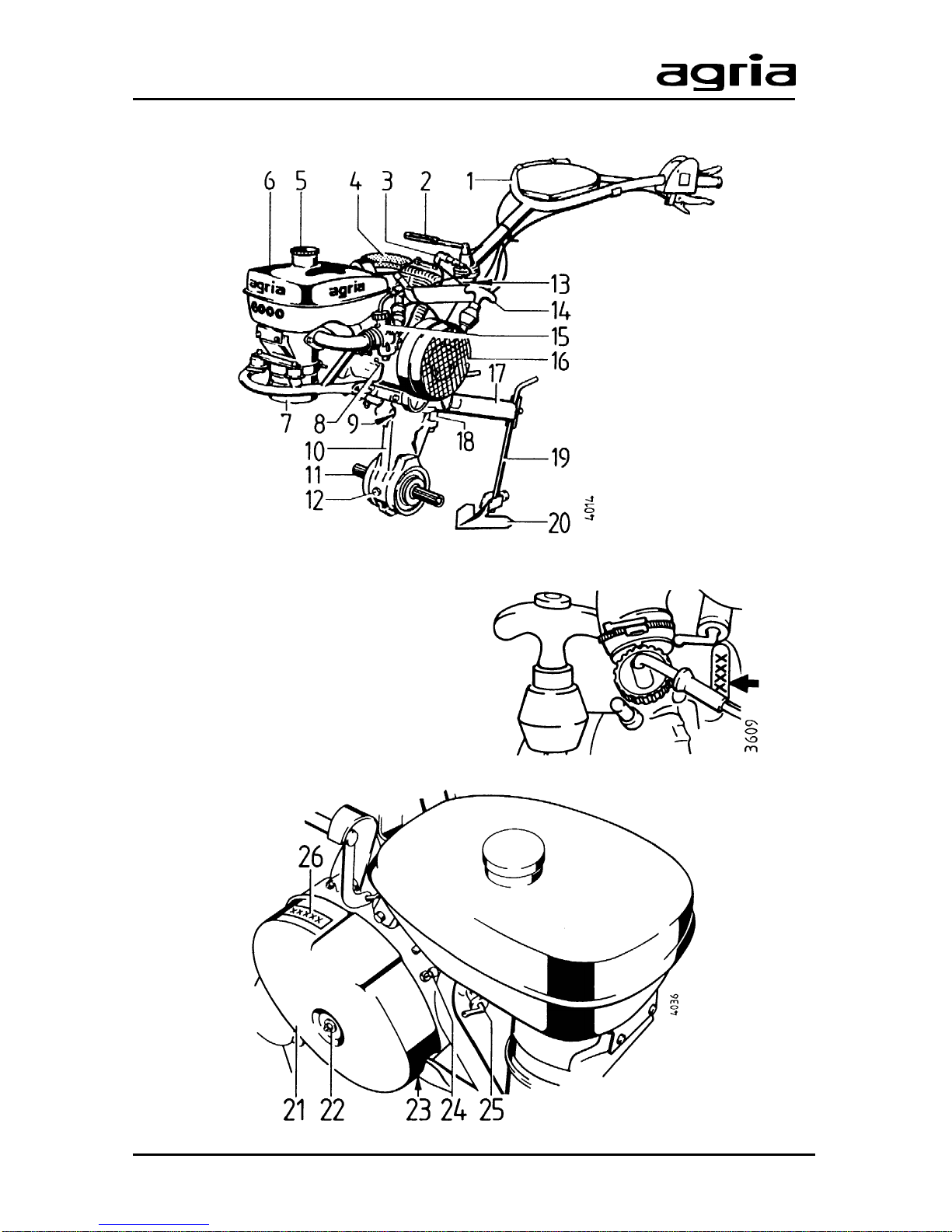
1 Steering handle
2 T ensioning lever for steering handle side adjustment
3 Spark plug / spark plug connector
4 Exhaust
5 Fuel tank lid
6 Fuel tank
7 Oil immersed air filter
8 Manual gearbox – oil filling control plug
9 T ubes for attachment of guards
10 Hoeing drive
11 Hoeing shaft
12 Hoeing drive – lubricant control / filler plug
13 Steering handle height-adjustment hex head bolt
14 Starter handle
15 Carburetor
16 Cooling air-grille
17 Leg
18 Hitch
19 Hoeing leg
20 Hoeing share
21 Clutch / chain-drive housing cover
22 Cover attachment nut
23 Manual gearbox – oil drain plug
24 Chain tensioning screw
25 Fuel tap
26 Name plate/I.D. no.
27 Engine type plate
Page 5
Edition 11.98 Power Hoe 6000 5
Index
Amount of Delivery ..........................3
Recommendations
Lubricants, Anti-Corrosive Agents ......4
Fuel ....................................................4
Maintenance and Repair.....................4
Designation of Parts ..................5, 35
Assembly Instructions .....................7
1. Safety Instructions .................8–12
2. Specifications
Dimensions ......................................13
Power Hoe........................................13
Noise Level.......................................13
Engine ..............................................14
Operation on Slopes.........................1 4
3. Devices and
Operating Elements
Engine ..............................................15
Dead Stop Lever...............................16
Clutch ...............................................16
Gearbox ...........................................17
Hitch .................................................17
Steering Handle................................18
Drive-Wheels....................................18
Wheel-Weights .................................19
Front support wheel..........................20
Hoeing T ools.....................................20
Hoeing Guards .................................22
4. Commissioning and Operation
Commissioning the Machine ............23
Starting the Engine ...........................24
Switching off the Engine ...................25
Hoeing ..............................................26
5. Maintenance
Engine ..............................................27
Manual Gearbox ...............................29
Hoeing Drive ....................................30
Adjustments on Hand Levers ...........30
Dead Stop ........................................31
General Maintenance .......................31
Cleaning ...........................................31
Storage.............................................32
Lubricants, Varnishes,
Wear Parts.......................................33
6. Troubleshooting ....................34–35
7. Inspection and
Maintenance Chart .........................36
Electric Wiring Diagram .................3 7
Conformity Declaration ..................39
Note fold-out pages!
Fig. A + B...........................................5
Fig. C ...............................................38
Page 6

6 Power Hoe 6000 Edition 11.98
Recommendations
Lubricants and
Anti-Corrosive Agents:
Use the lubricants specified for engine
and gearbox (see “Specifications”).
We recommend using Bio-lubricating
oil or Bio-lubricating grease for “open”
lubrication points or nipples (as specified
in the operating instructions).
We recommend using Bio-slushing oil
to preserve machines and attachments
(do not apply on painted covers). Y ou can
brush or spray the oil.
Anti-corrosive agents are environmentally friendly and degrade fast.
Using ecologically safe Bio-lubricants
and Bio-anti-corrosives, you contribute to
environmental protection and to the
wellbeing of humans, animals and plants.
Fuel
The 2-stroke-engine runs on commercial oil-petrol mixtures (for the specified
stoichiometric ratio refer to “Specifications”). Unleaded regular and
supergrade petrol as well as leaded
supergrade petrol can be used for the
fuel mixture. However, only use selfmixing special 2-stroke-engine oil (refer
to “Specifications”, p15).
If, for environmental reasons, you use
unleaded petrol, make sure the fuel is
drained completely when shutting
down the engine for more than 30 days.
This is to prevent resin residue from
depositing in the caburetor , fuel filter,
and tank. Or add a fuel stabilizing liquid
to the fuel.
When storing the machine at the end
of the season, also drain leaded fuel
completely or add a fuel stabilizing liquid.
For further instructions see “Engine
Preservation”.
Maintenance and
Repair:
The trained mechanics of your agria
workshop expertly carry out any maintenance and repair work.
Y ou should only carry out major maintenance work and repairs on your own,
if you have the proper tools and knowledge of machines and internal combustion engines.
Do not hammer against the flywheel
with a hard object or metal tools as it
might crack and shatter in operation,
causing injuries and damage. Only use
suitable tools to pull off the flywheel.
Page 7
Edition 11.98 Power Hoe 6000 7
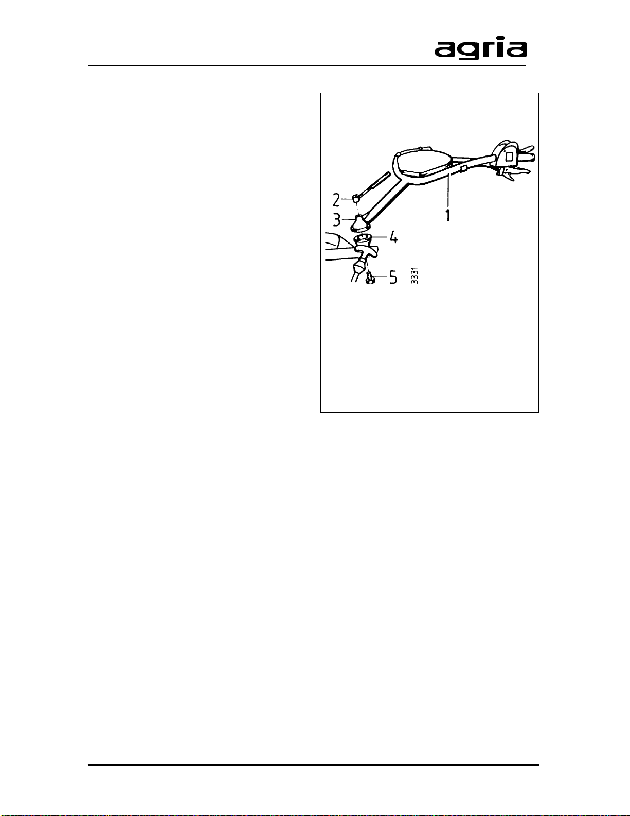
Unpacking and Assembly
1 Steering handle
2 T ommy nut
3 Locking plate on steering handle
4 Locking plate on joint
5 Hex head bolt
l
Open the top of the cardboard box.
l
Remove tommy nut (2). T ake hex head
bolt (5).
l
Place the steering handle (1) onto the
locking plate (4) and hold it in place.
Ensure no Bowden cables or electric
cables are twisted or squeezed as you
are doing this.
l
Insert the hex head bolt (5) from the
bottom through the joint and the steering
handle.
l
Attach the tommy nut (2).
l
Move the steering handle until its teeth
engage with the locking plate teeth.
Tighten the tommy nut.
l
Attach the Bowden cables and electric line to the handlebars using the clips.
l
Steering handle removal is in reverse order.
l
To start up, carry out all steps described on page 23.
Page 8
8 Power Hoe 6000 Edition 11.98
1. Safety Instructions
Before starting the engine, read the operating instructions and note:
Warning
This symbol marks all paragraphs affecting your safety. Pass all safety instructions to other users and operators.
Due Use
The power hoe has exclusively been
designed for all common applications and
tasks in agriculture, forestry , horticulture,
grass and park maintenance (due use).
Any other type of use is considered undue. The manufacturer is not liable for any
damages resulting from undue use, for
which the risk lies with the user alone.
Due use includes compliance with manufacturer’s instructions on operation, maintenance and repair.
Any unauthorized changes to the power
hoe render manufacturer liability null and
void.
General Instructions
on Safety and
Accident Prevention
Basic Rule:
The standard accident prevention regulations must be adhered to, as well as all
other generally accepted rules governing operational safety, occupational
health and road traffic regulations.
For travelling on public roads, the current
traffic code applies.
Check the power hoe for road and operational safety each time you take up
operation.
Only persons familiar with the power hoe
and instructed on the hazards of operation are allowed to use, maintain and
repair the machine.
Teenagers of 16 years or younger may
not operate the power hoe!
Only work in good light and visibility .
Operator’s clothes should fit tight. Avoid
wearing loose fitting clothes. Wear solid
shoes.
Note the warning and instruction signs
on the power hoe for safe operation.
Compliance is for your own safety .
When transporting the power hoe on
vehicles or trailers outside the area to be
cultivated, ensure that the engine is
turned off.
Careful with rotating tools – keep at a safe
distance!
Page 9

Edition 11.98 Power Hoe 6000 9
1. Safety Instructions
Beware of coasting tools. Before you start
any maintenance or repair on them, wait
until tools have come to a complete stop.
Foreign powered parts shear and crush!
Riding on the attachment during opera-
tion is not permitted.
Attachments and their weight affect the
driving, steering, braking, and tip-over
characteristics of the power hoe. Therefore, ensure steering and braking functions are sufficient. Match operating
speed to conditions.
Do not change governor settings. High
engine speed increases risk of accidents.
Working Area and
Dangerous Area
The user is liable to third parties working
within the power hoe’s working range.
Staying in the hazardous area of the
power hoe is not permitted.
Check the immediate surroundings of the
power hoe before you start it. Watch out
for children and animals.
Before you start work, clear the area from
any foreign object. During operation,
always watch out for further objects and
remove them in time.
For operation in enclosed areas, ensure
that a safety distance is kept to enclosures to prevent damage to tools.
Operation and
Safety Devices
Before you start operation
Become familiar with the devices and
operating elements and their functions.
Above all, learn how to turn off the engine quickly and safely in case of an
emergency .
Ensure that all protective devices are
mounted and positioned to provide protection.
With no attachment mounted, make sure
PTO-shaft is covered with the protective
cap.
Starting the engine
Do not start engine in closed rooms. The
carbon monoxide contained in the exhaust fume is extremely toxic when inhaled.
Before you start the engine set all operating elements to neutral or idling position.
For starting the engine, do not step in front
of the power hoe and the attachment.
Operation
Never leave the operator’s position at the
steering handle while power hoe is at
work.
Never adjust the steering handles during
work – danger!
Page 10

10 Power Hoe 6000 Edition 11.98
1. Safety Instructions
For any operation do not leave the operator’s position as defined by the steering handle, especially not when you turn
the machine.
Riding on the attachment during operation or in transport is not permitted.
If clogging occurs in the attachment, turn
off the engine and clean the attachment
with an appropriate tool.
In case of damage to the power hoe or to
the attachment, immediately turn off the
engine and have it repaired.
If steering causes problems, immediately
bring the power hoe to a halt and turn it
off. Have the malfunction removed without
delay .
T o prevent the power hoe from sliding on
slopes make sure it is secured by another
person using a bar or a rope. This person
must be located at a higher position than
the vehicle at a safe distance from the
attachment at work.
If possible, always work horizontally to
the slope.
End of Operation
Never leave the power hoe unattended
with the engine running.
Before you leave the power hoe, turn off
the engine. Then close fuel tap.
Secure power hoe against unauthorized
use – remove spark plug connector.
Attachments
Only mount attachments with the engine
and attachment drive switched off.
Always use appropriate tools and wear
gloves when changing attachments and
parts thereof.
For mounting and dismounting attachments bring support leg into proper position and ensure stability .
Secure power hoe and attachments
against rolling off (wheel wedge).
Beware of injuries when coupling attachments. Proceed with extreme caution.
Mount attachments as specified and only
couple at specified points.
Secure power hoe and attachment
against unauthorized use and rolling off
when you leave the machine. If necessary , install transport or security devices
and secure.
Hoeing Attachment
Adjust protective hood of hoeing attachment so that only those parts of tools
which penetrate the soil are not covered.
When hoeing, make sure hoeing skid is
adjusted properly .
Page 11

Edition 11.98 Power Hoe 6000 11
1. Safety Instructions
Maintenance
Never carry out any maintenance or
cleaning with the engine running.
In addition, always remove spark plug
connector before you work on the engine.
Check regularly and, if necessary, replace all protecting devices and tools
subject to wear and tear.
Replace damaged cutting tools.
Always wear safety gloves and use
proper tools when exchanging cutting
tools.
Do not carry out repairs like welding,
grinding, drilling, etc. on structural and
safety-relevant parts (e.g. coupling devices)!
Keep power hoe and attachment clean
to avoid risk of fire.
Check nuts and screws regularly for tight
fit and re-tighten, if necessary .
Ensure that you re-install all safety and
protective devices and adjust them properly after maintenance and cleaning.
Only use original agria spare parts. All
other commercial spare parts must correspond to quality and technical requirements specified by agria.
Storage
It is not allowed to store the power hoe in
rooms with open heating.
Never park the power hoe in closed
rooms with fuel left in tank. Fuel vapours
are hazardous.
Engine, Fuel, and Oil
Never let the engine run in closed rooms.
Extreme danger of intoxication!
Careful when dealing with fuel. Great
danger of fire! Never refill fuel close to
open fire, inflammable sparks or hot
engine parts. Do not refill fuel in closed
rooms. Do not smoke when refilling!
Refill only with the engine switched off
and cooled down.
Do not spill any fuel, use a proper filling
device.
In case of fuel-spillage, push the power
hoe away from the spillage before you
start the engine.
Make sure fuel is of specified quality .
Store fuel in approved cans only .
Store anti-corrosive agents and stabiliz-
ing liquids out of reach of children. If sickness and vomiting occur , see a doctor. If
fuel has contacted eyes, rinse them
thoroughly , avoid inhaling of vapours.
Read and observe enclosed instructions.
Page 12

12 Power Hoe 6000 Edition 11.98
1. Safety Instructions
Before you dispose of opened and seemingly empty pressurised tins make sure
they are completely empty . Empty them
in ventilated places safe from spark
formation or flames. If necessary , dispose
of tins in hazardous waste deposits.
Careful when draining hot oil, danger of
burns.
Make sure oil used is of specified quality .
Storage is in approved cans only .
Dispose of oil, greases, and filters
seperately and properly .
Tyres and
Tyre Air Pressure
When working on tyres, make sure power
hoe is parked properly and secured
against rolling off.
Any repairs are to be carried out by
trained mechanics only and with the
appropriate tools.
Regularly check tyre air pressure. Excessive air pressure may cause bursts.
Use appropriate tyre air pressure when
mounting front weight.
Re-tighten attachment bolts of drivewheels or check tightness when doing
maintenance work.
Electrical System and
Battery
Persons having a pacemaker may not
touch live parts of the ignition system
when the engine is running.
Explanation of
Warning Signs
Before any cleaning, maintenance, and
repair work switch off the engine and pull
spark plug connector.
With engine running, keep at a safe distance from hoeing tools.
Do not work without protective covers
mounted. Before starting the engine, bring
covers into proper position.
Page 13
Edition 11.98 Power Hoe 6000 13
2. Specifications
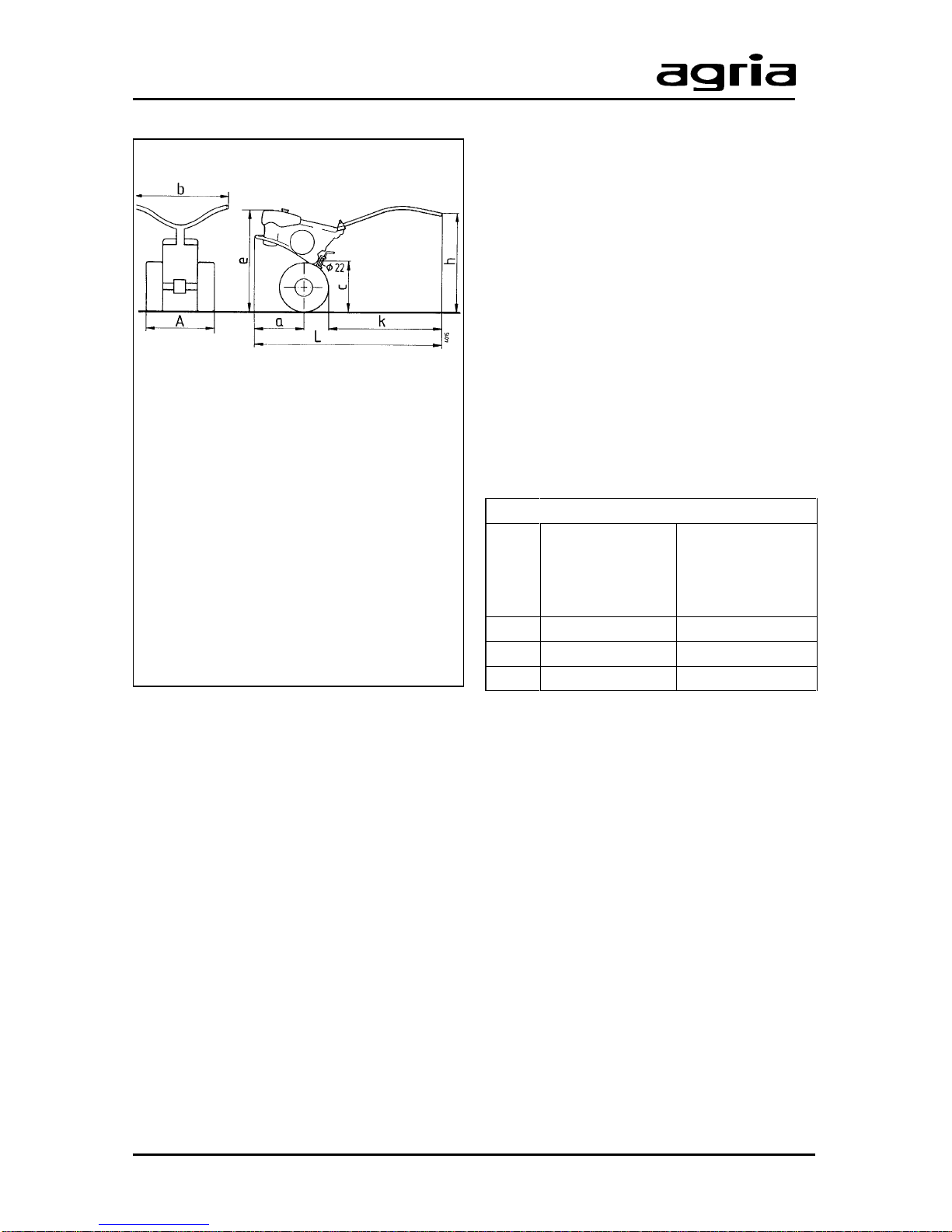
Machine Dimensions:
a..........................................310 mm
b..........................................620 mm
c........................................1000 mm
d..........................................890 mm
h............................. ca.700–950 mm
l.........................................1250 mm
A ................................. 100–650 mm
(depending on type of tilling attachment)
Manufactured according to
CEN/GS safety standards:
e.......................................> 150 mm
f ............... > 500 mm at h = 800 mm
Accessories:
Hoe 34–100 cm
Front support wheel...............0189 421
Ridger....................................3452 021
Wheel hubs ...........................6019 511
Drive-wheels .........................0190 111
Wheel weights .......................0421 011
Hitch ......................................4040 021
Conventional plough ..............3441 021
Quarter-turn plough ...............3444 021
Potato raising plough .............3443 021
Spring tine cultivator ..............3472 021
Combined rotary harrow ........3473 021
Model designation ..................... 6000
Gearbox ........3-speed manual gearbox
and 1 roller chain driving
hoeing shaft/wheel shaft
Oil filling quantities
Gearbox in engine block
T ransmission oil BP TFJD-GL4 .....0.30l
in chain drive top
T ransmission semi-fluid grease .... 350g
BP Energrease LS-EP00
in hoeing drive
T ransmission semi-fluid grease .... 350g
BP Energrease LS-EP00
Hoeing width:........ Depending on type
of hoeing accessory
Tyres:....................... 5.0-10 (field tyre)
Tyre pressure: ........................... 1.2bar
Noise levels:
In accordance with German 3rd Ordinance on machine-safety law:
Noise level at operator’s ear ......90dBA
Sound level...........................101.5dBA
(in accordance with regulations of
German Agricultural Association)
Clutch: ............................Oil immersed
multi-plate clutch
Weight: .......................... approx. 56kg.
Speed steps
Gear
Hoeing tool
[rpm]
Ground speed
[km/h]
with 5.0-10
tyres fitted
1 66 6
2 98 9
3 172 15.7
Page 14

14 Power Hoe 6000 Edition 11.98
2. Specifications
Engine
Manufacturer:..............................agria
Type: .................................... 66/6 or 1*
Version: ........................ Fan-air-cooled
1-cylinder-2-stroke engine (petrol)
Lubrication:............. Petroil lubrication;
stoichiometric ratio 1:30
Bore: ........................................ 56 mm
Stroke: ..................................... 58 mm
Cubic capacity: ..................... 150 ccm
Compression: .............................. 6 :1
Output: .................................... 4.8 kW
at 4500 rpm
Spark plug:..................... Bosch M10A
Spark plug gap ................ 0.5…0.6 mm
Ignition system: ................... Flywheel
magnet ignition
Contact clearance ....... 0.35…0.45 mm
Ignition point ............... 2.5 before u.d.c.
radio remote screened according to
VDE 0879
Starter:........................... Recoil starter
Stop device: ................. Contact break
via short circuit cable
Engine-stop-switch on handlebar
Generator: .............................. 6V A.C.
Fuel tank capacity: ......... approx. 4.5 l
Fuel: ..................................Commercial
petrol/oil mixture 1:30
octane number min. 90 RON
and self-mixing
supergrade 2-stroke engine oil, e.g.
Shell: Super T , Super TX;
Esso: Exxon Special 2T Engine oil;
BP: 2T Special
(refer to fuel recommendations)
Air filter: .....................Oil bath air filter
Engine oil filling
quantity: ......................... approx. 150ml
Carburetor:...... Piston slide carburetor
Bing 1/18/31 or 1/18/106
Air control screw: ....... in basic setting
approx. 1/2…11/2 revs. open
Main jet: .......................................... 95
Idle jet: ............................................ 45
Needle jet: .................................. 1108
Needle setting:................................. II
Rated speed: ....................... 4800 rpm
Top no-load speed:............. 6300 rpm
Idling speed: ....................... 1800 rpm
Operability on Slopes:
Engine is suited for use on slopes:
continuous operation possible
up to .................. 45° inclination (100%)
Page 15
Edition 11.98 Power Hoe 6000 15
3. Devices and Operating Elements
The power hoe agria 6000 is suited for
common horticultural, agricultural, and
forestal operations, and for grass and
park maintenance.
The following attachments are available:
l
Hoeing attachment 34–100 cm
l
Ridging attachment
l
Draft attachments for soil cultivation
Engine
The two-stroke-petrol engine runs on
commercial petrol/oil mixture of a stoichiometric ratio 1:30. For the first tank
filling use a ratio of 1:25.
I
Note! Only use self-mixing special 2-stroke engine oil (see
“Specifications”).
Also, refer to fuel recommendations, p4.
During the first 20 operating hours (break-
in period) do not use engine to maximum
power.
Even after break-in period never use
engine at higher speed than necessary
for the work in hand.
I
High engine speed is harm-
ful to any engine and con-
siderably affects its durability .
This applies especially for no load operation. Any overspeed (have the engine roar) can result in immediate
damage.
Cooling System
The engine is fan-cooled. Therefore keep
screen at recoil starter and cooling ribs
of cylinder clean and free from sucked-in
plant trash.
Always ensure that idling-speed is adjusted correcty. At low speeds and with
the speed control lever set to idle, the
engine is supposed to run smoothly and
without run-out.
Air Filter
The air filter purifies the air intake. A
clogged filter reduces engine output.
Ignition System
The engine is equipped with a maintenance-free, contactless electronic ignition
system. We recommend to have
necessary check-ups done by an expert
only.
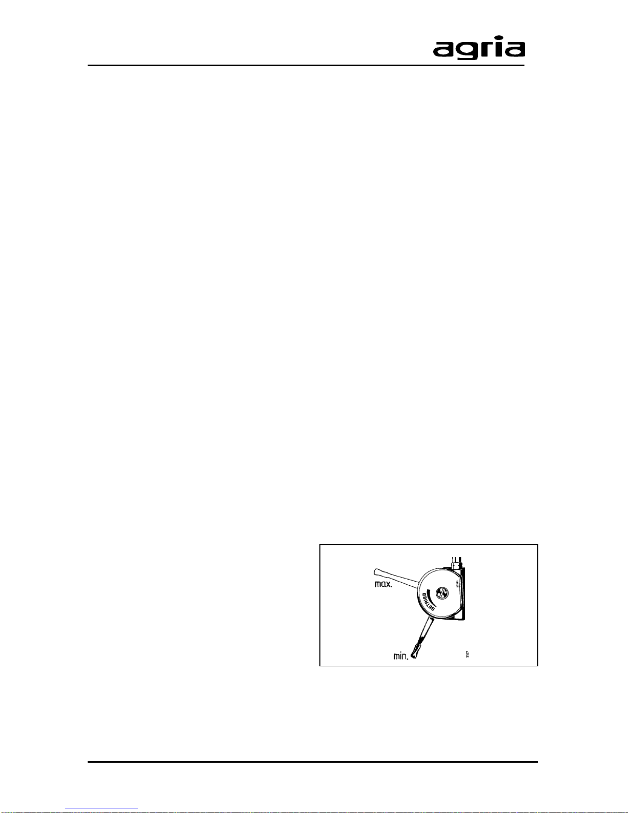
Speed Control Lever
The speed control lever (C/8) on the
steering handle is for stepless setting of
engine speed from min. = idle to max. =
full throttle.
Page 16
16 Power Hoe 6000 Edition 11.98
3. Devices and Operating Elements
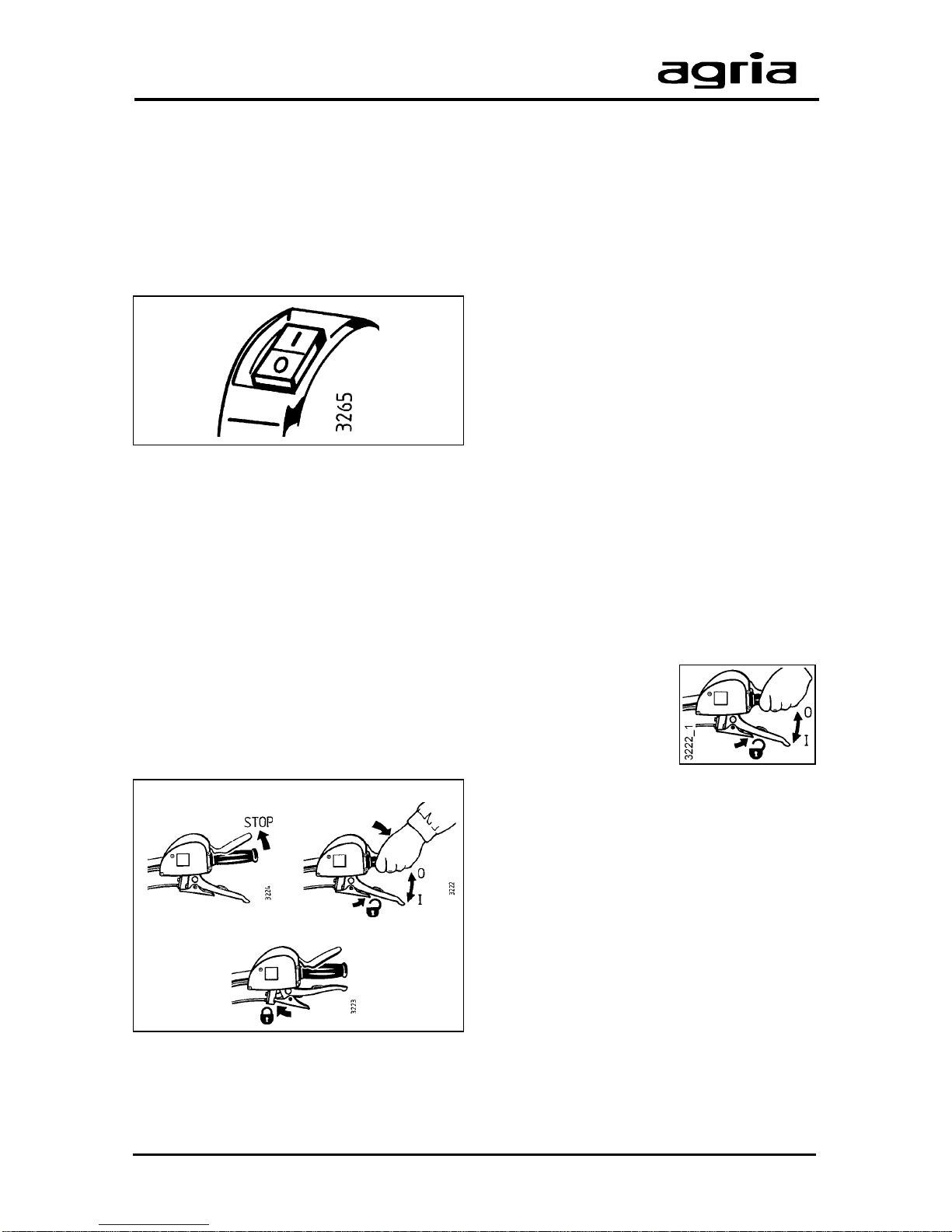
STOP position Operating position
Start position
Engine-off-switch
The power hoe is equipped with an electric off-switch (C/4). On pressing the
switch, the ignition is turned off (engine
is switched off).
Position "I" = Operation
Position "0" = Engine off
I
The engine-off-switch also
serves as emengency-off-
switch. Set the switch to “0” for
fast switch-off.
Dead Stop Lever
The power hoe is equipped with a safety
switch (lever C/5). Upon release of the
lever, the ignition system is turned off
(engine is off).
l
Stop position: Upon release of the
lever , the ignition system is switched off
(engine is off). Beware – engine keeps
running due to centrifugal mass.
l
Start position: For starting the engine
and for short breaks, pull the hand clutch
lever (C/6) and fasten with pawl (C/7).
l
Operating position: To operate the
machine press dead stop lever (C/5).
W
Do not tie down dead stop lever.
I
The dead stop lever also serves
to switch off in an emergency.
Release the dead stop lever for
fast engine switch-off. The lever automatically goes to STOP position.
Clutch
The power hoe is equipped with a multi
plate disk clutch, running in an oil bath.
Clutch is engaged with hand clutch lever
(C/6).
The machine is decoupled when you pull
the hand clutch lever. Now, the engine
stops driving the mower. The pulled hand
clutch lever can be
locked with pawl (C/7).
T o avoid clutch slipping
away during operation,
a clutch play of 3–5 mm
is factory-set on the hand lever.
After the first operating hour, the clutch
play has to be checked and, if necessary ,
re-adjusted (refer to “Maintenance”).
Page 17
Edition 11.98 Power Hoe 6000 17
3. Devices and Operating Elements
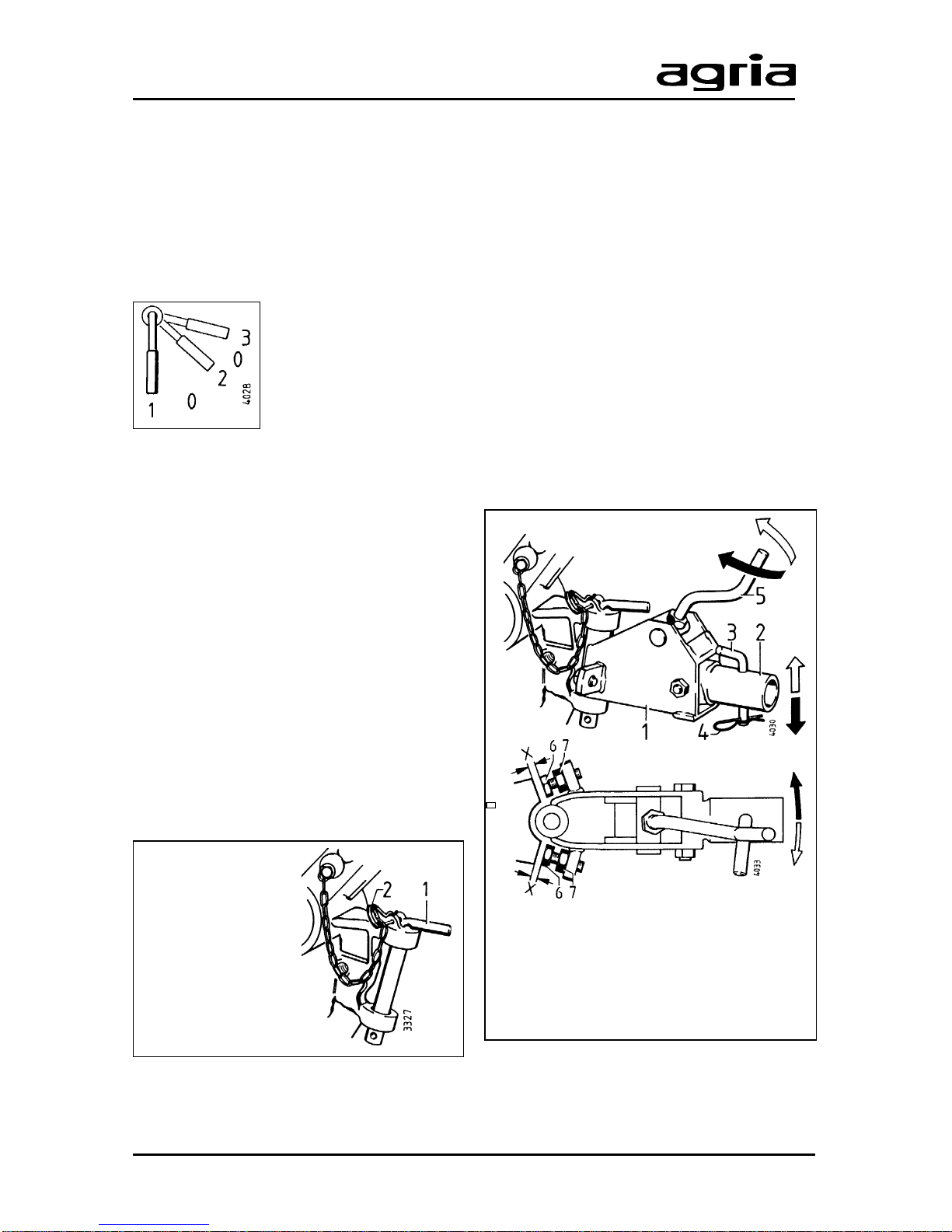
1 Locking pin
2 R-clip
1 Coupling unit
2 Adapter tube
3 Locking pin
4 R-clip
5 Crank
Gearbox
The power hoe has a 3-speed manual
gearbox that drives the wheels and the
tiller.
Speed steps
Lever (C/3) shifts the
gears on wheel-drive
and hoeing-drive:
I .............................................. 1st gear
II ............................................ 2nd gear
III ............................................ 3rd gear
0 ................................................neutral
A roller chain transmits power to the shaft
that drives the wheels and the hoeing unit.
I
Only change gears when clutch
is decoupled. Move shift lever
only with your hand.
Hitch
T railed implements, for example leg and
plough, are pin-attached (1) to the hitch
(A/18).
Ensure the pin is locked in place with the
R-clip (2) after the implement is attached.
Coupling Unit
The coupling unit (1) is an adapter that
serves as a link between the hitch and
the mounted attachments (plough, cultivator and combined rotary harrow).
These attachments have a coupling pin
that is inserted into the adapter tube (2).
Attach the pin (3) with the locking pin and
lock with R-clip (4).
The crank (5) on the coupling device
allows setting individual working depths.
Set the travel ”X” with the stop bolts 6
and 7 to adjust the hoe's steering when
an attachment is mounted.
Page 18
18 Power Hoe 6000 Edition 11.98
3. Devices and Operating Elements
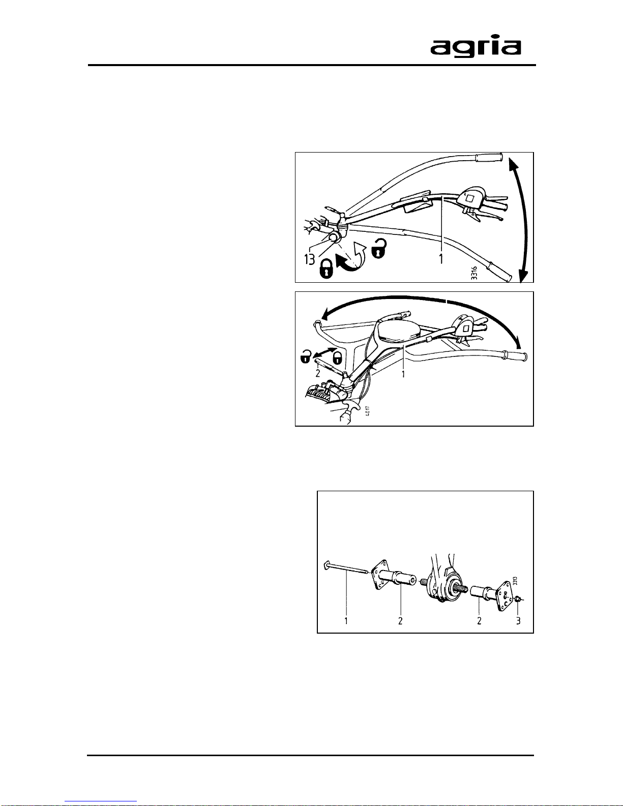
1 Anchoring bolt
2 Wheel hub
3 Locking nut
Steering Handle
Steering handle height
adjustment
l
Undo hex bolt (13) until the teeth are
exposed.
l
Adjust the handlebars to the desired
height and notch the teeth into the
proper teeth of the pivoting joint.
l
Tighten the hex bolt.
Steering handle side
adjustment
l
Undo tommy screw (1) until the
teeth are exposed.
l
Move the handlebars to the proper
position.
Drive-Wheels
A choice of hubs are available to be
mounted to the drive-wheels:
l
one pair of wheel hubs to suit a rigid
wheel shaft;
l
one pair of latch hubs to give easier
turns.
One pair of wheel hubs
(rigid version)
Assembly
l
Attach wheel hubs (2) to both ends of
the hoeing shaft.
l
Guide the anchoring bolt (1) through
the hubs and the shaft as shown in the
illustration.
l
Attach locking nut (3) and tighten it
(100Nm).
Page 19
Edition 11.98 Power Hoe 6000 19
3. Devices and Operating Elements
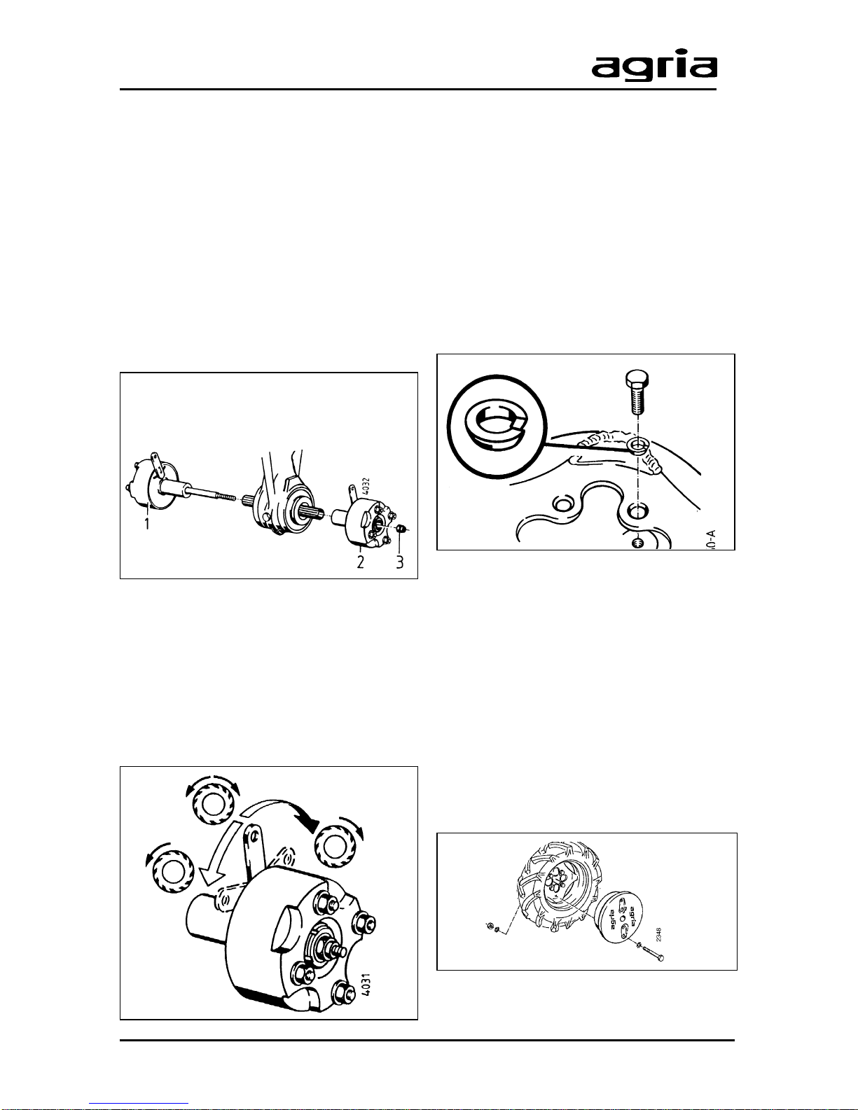
1 Latch hub with anchoring bolt
2 Latch hub without anchoring bolt
3 Locking nut
One pair of latch hubs
(assist turning)
Assembly
l
Attach the latch hub (1) together with
anchoring bolt to the hoeing shaft, as
shown in the picture.
l
Attach the latch hub (2) without anchoring bolt to the opposite shaft end.
l
Attach locking nut (3) and tighten it
(100Nm).
Latch hubs can be adjusted as required
via the levers.
l
Middle position = rigid connection
l
Forward position = Drive and freewheeling for forward operation
l
Backward position= Drive and freewheeling for reverse operation
Fitting the drive-wheels
The drive-wheels can be fitted to the hubs
in two ways, pointing inside or outside to
give the desired track width.
For full tractive power , mount the wheels
with the pointed parts of lugs pointing in
travelling direction (wheels seen from
above). Fit the ball spring washers with
the ball side pointing to the recess in the
disk wheel.
On new machines and after each wheel
change retighten the wheel bolts and nuts
at 100Nm after the first 2 operating hours,
otherwise retighten each time you
maintain the machine.
Wheel-Weights
Wheel weights are available to improve
traction.
Wheel weight ........... Item no. 3221 011
to be fitted to drive-wheels 5.0-10
Page 20
20 Power Hoe 6000 Edition 11.98
3. Devices and Operating Elements
Attachment of
Hoeing Tools
W
Always shut off the engine
and remove the spark plug
connnector before you attach/remove the hoeing tools. Wear
safety gloves.
l
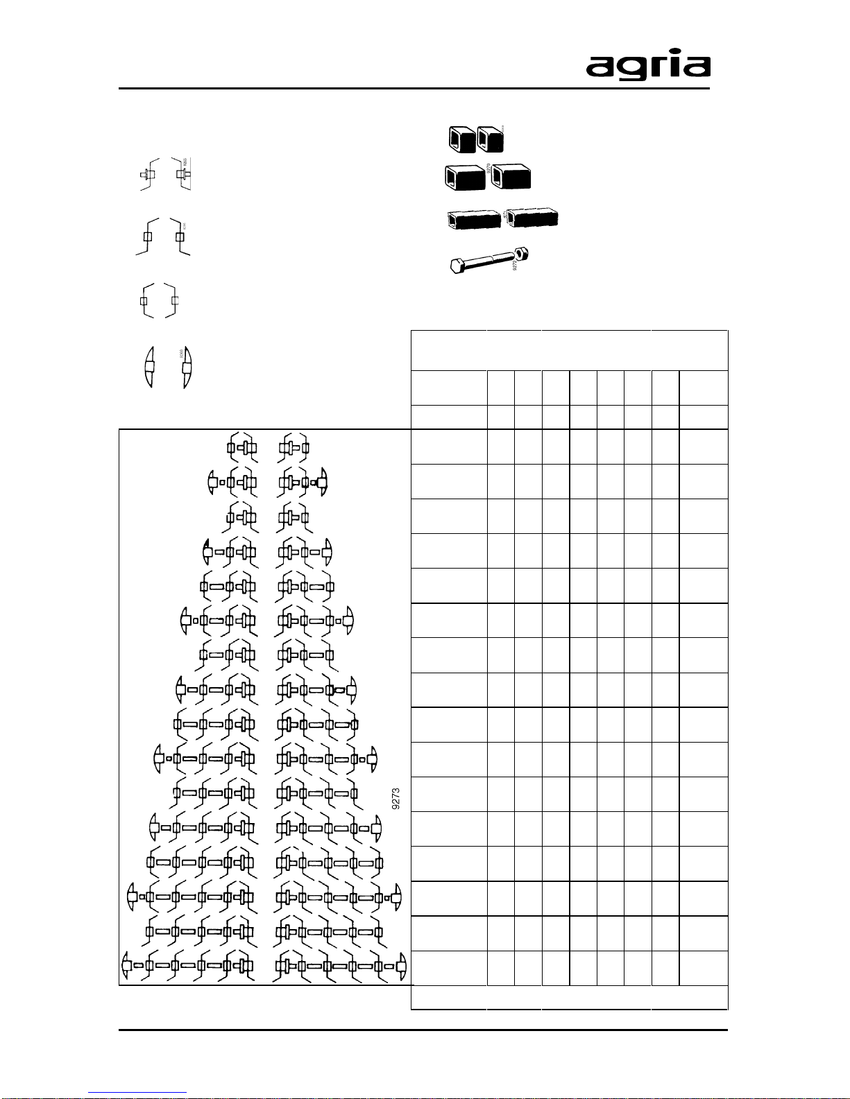
Assemble the hoeing tools (A–C) using distancer sleeves (E–G) and guard
discs (D), if necessary, to obtain the
desired working width (see ”Combinations of hoeing tools”, p21) and push them
on the shaft.
l
Insert the anchoring bolt (H) through
the tools and shaft.
l
Attach locking nut and tighten it at
100Nm.
Guard discs
The discs are to prevent shrubs and
bushes from being damaged by the hoe
and to protect young plants from being
covered with soil.
They also provide protection for the operator when hoeing along headlands or
fences.
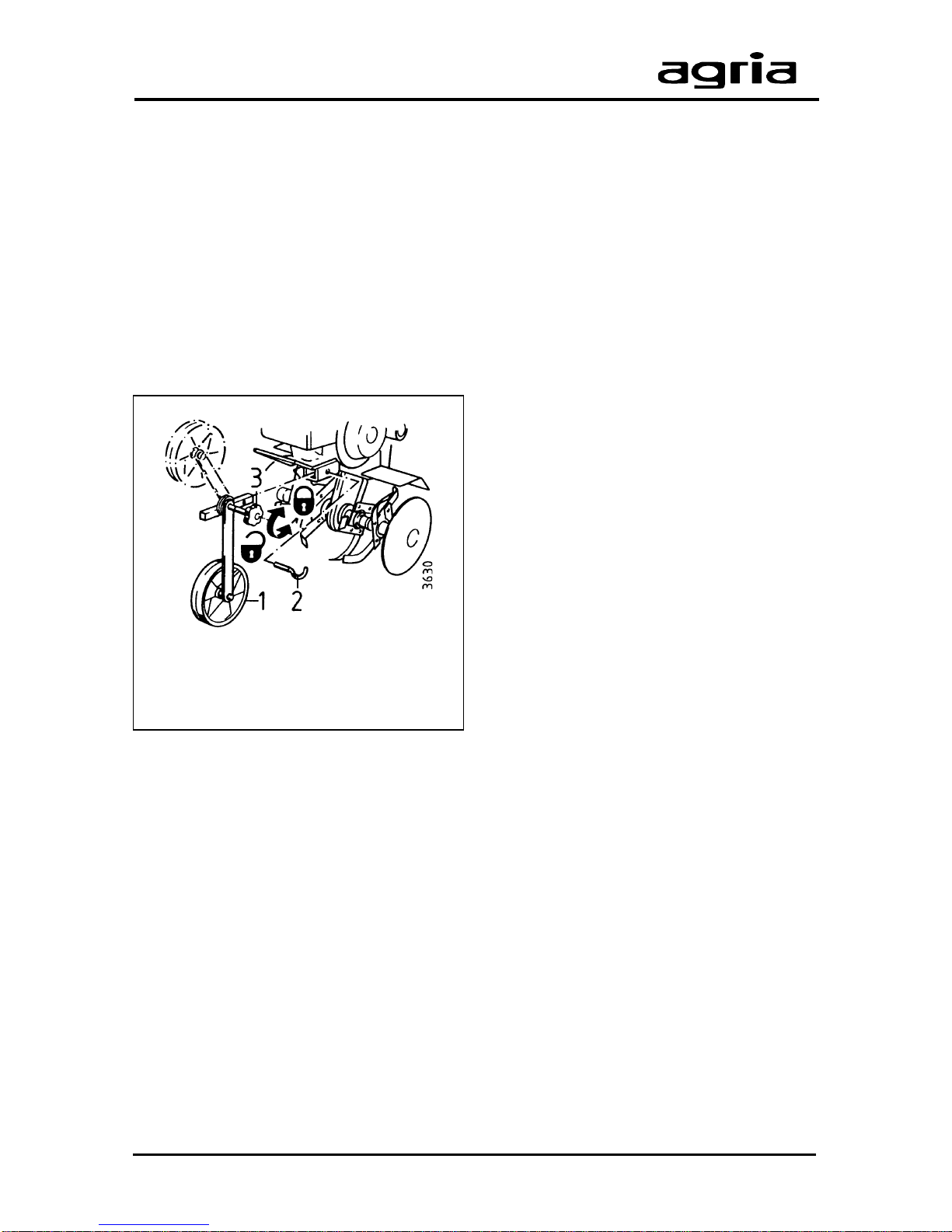
1 Front support wheel
2 Linch pin
3 Grip screw (clamping screw)
Front support wheel
(Accessory no. 0189 421)
For easier transport, use the front support wheel.
Installing the front support wheel
Push the square pin on the support wheel
(1) all the way in the rectangular tube and
connect both parts with a linch pin (2)
fitted through the borings.
T o keep the front support wheel mounted
on the power hoe fold it up for hoeing.
Hoeing position
l
Loosen grip screw (3) until the notches
on the beam are released.
l
Fold the beam up into a mesh with the
notches and tighten the grip screw .
Transport position
l
Fold the support wheel down and
tighten the grip screw .
Page 21
Edition 11.98 Power Hoe 6000 21
3. Devices and Operating Elements
Hoeing Tools
A pair of
base hoeing tools
B pair of
add-on hoeing tools
C pair of
end hoeing tools
D pair of
guard discs
Combinations of hoeing tools
Width A B C D E F G H
cm mm
34 1 1 350
34/42* 1 1 1 1 400
42 1 1 350
42/50* 1 1 1 1 1 480
52 1 1 1 1 540
52/60* 1 1 1 1 1 585
60 1 2 1 1 540
60/68* 1 2 1 1 1 1 665
70 1 2 2 730
70/78 1 2 1 1 2 780
80 1 3 1 2 730
80/88* 1 3 1 1 1 2 860
90 1 3 3 920
90/98* 1 3 1 1 3 970
100 1 4 3 920
100/100* 1 4 1 1 3 1050
* Total width with guard discs fitted
E
pair of distancer sleeves
F pair of distancer sleeves
G pair of distancer sleeves
H pair of anchoring bolts
Page 22
22 Power Hoe 6000 Edition 11.98
3. Devices and Operating Elements
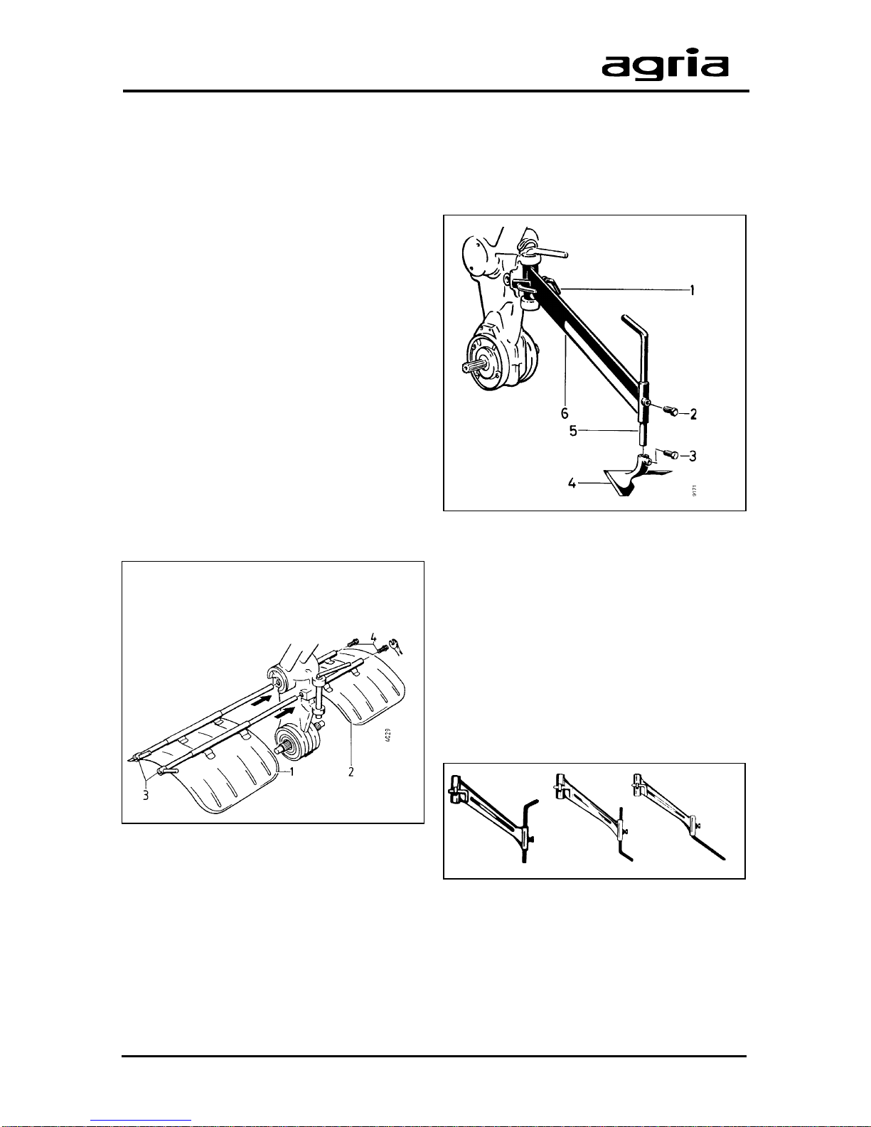
Hoeing guards
Assembly
The guards must cover the hoeing tools
across the whole working width.
W
Always shut off the engine
and remove the spark plug
connnector before you attach/remove the hoeing guards. Wear
safety gloves.
l
Fit both hoeing guards (1+2) with
anchoring bolts (3) and tensioning bolts
(4) into the holes (A/9) on the hoeing drive
(see illustration).
W
Before you start hoeing ensure guards of the correct
size are mounted to prevent
injuries caused by the rotating hoeing
tools.
Hoeing leg
l
Attach hoeing leg (5) and leg (6) to the
hitch.
The hoeing leg slows down the hoe’s
forward speed. Press the hoeing leg (5)
into the soil for the desired working depth.
The deeper you set the leg setting, the
deeper is the working depth.
Hoeing leg settings
A = in heavy soil
B = in medium to light soil
C = in sandy soil
The share (4) is for working in losened
soil only .
A
BC
1 Left hoeing guard
2 Right hoeing guard
3 Anchoring bolt
4 T ensioning bolt
Page 23
Edition 11.98 Power Hoe 6000 23
4. Commissioning and Operation
oil level
Commissioning the
Machine
Please note that durability and operational safety of the engine depend to a
large extent on its breaking-in. Always
allow a cold engine to warm up for some
minutes and never run it at full throttle at
the beginning. Please note: for the first
20 hours of operation (break-in period)
do not use the engine at full power.
I
Make sure you check and
maintain air filters regularly
and use clean fuel. Only use
branded petrol.
Only use fresh, clean fuel (not older than
3 months) and approved fuel cans to be
purchased in special shops. Rusty sheet
metal cans or fuel cans not suited for
petrol are not permitted.
For the first commissioning or after longer
periods of no operation, fill fuel tank to
maximum to avoid starting problems.
Do not cause fuel tank to overflow, but
leave a 5 mm margin for the fuel to expand.
W
Be careful when dealing with
fuel. Great danger of fire!
Never refill fuel close to open
fire, inflammable sparks or hot engine
parts.
l
Do not refill fuel in closed rooms.
l
Do not smoke when refilling!
l
Refill only with the engine switched
off and cooled down.
l
Do not spill any fuel, use a proper
filling device.
Each time you take up operation, i.e.
before you start the engine, check
whether
l
the fuel tank contains enough fuel,
l
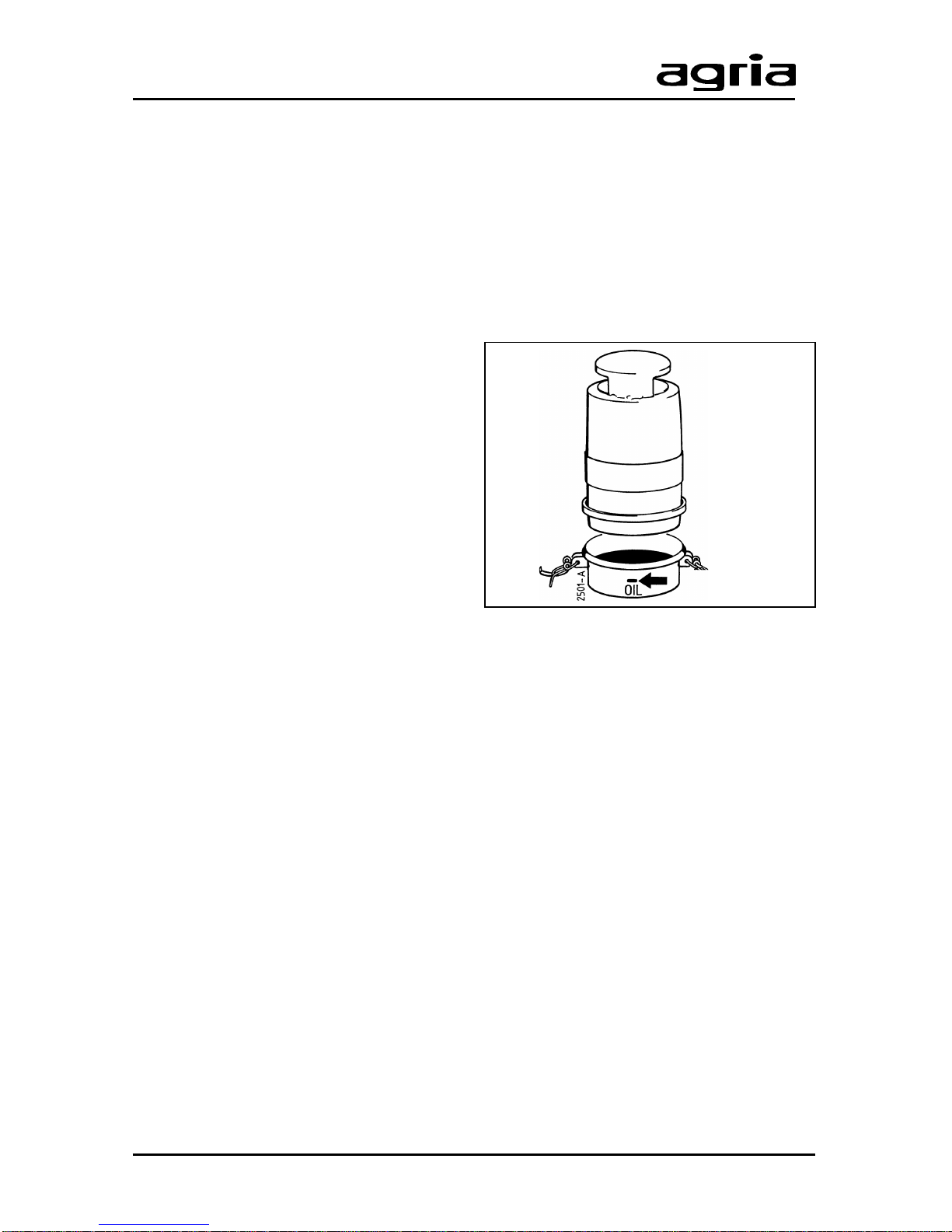
the oil filling mark in the pot of the oil
bath air filter shows an adequate level of
engine oil (filling quantity approx. 50 ml).
l
transmission oil level in manual gearbox reaches the control opening (B/28)
(for checking, bring engine into horizontal position).
W
Only take power hoe into operation with all protective devices mounted and positioned
to provide protection!
l
Careful when starting the engine in
closed rooms!
l
Ensure good ventilation and fast
escape of exhaust fumes. Exhaust
fumes contain carbon monoxide
which acts toxic when inhaled.
l
Do not touch the hot engine – danger of burns!
l
Do not touch the ignition cable and
do touch or remove ignition spark
connector while the engine is running.
Page 24
24 Power Hoe 6000 Edition 11.98
4. Commissioning and Operation
1/4
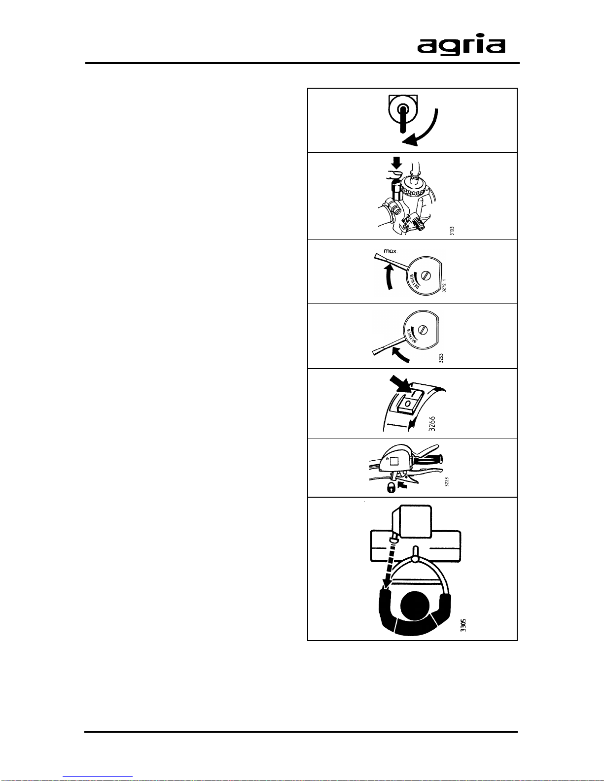
Starting the Engine
l
Open fuel tap (B/21)
Engine cold:
l
Press tickler (B/23) on carburetor until
fuel overflows.
l
Set speed control lever (C/7) to “max”
(full throttle).
Engine warm:
l
Do not actuate tickler on carburetor.
l
Set speed control lever (C/7) to
approx. 1/4 throttle.
l
Move engine-off-switch (C/3) to oper-
ating position “I”.
l
Pull hand clutch lever (C/5) and lock
with pawl (C/6) (start position).
l
Pull starting-rope on handle (B/29)
until you feel starter clutch engage. Then
pull hard and fast to start the engine.
After the start, let rope glide back. Do not
let snap.
l
Once the engine has started, slowly
move speed control lever to centre position and let engine warm up for some
time.
Page 25
Edition 11.98 Power Hoe 6000 25
4. Commissioning and Operation
6
30 sec
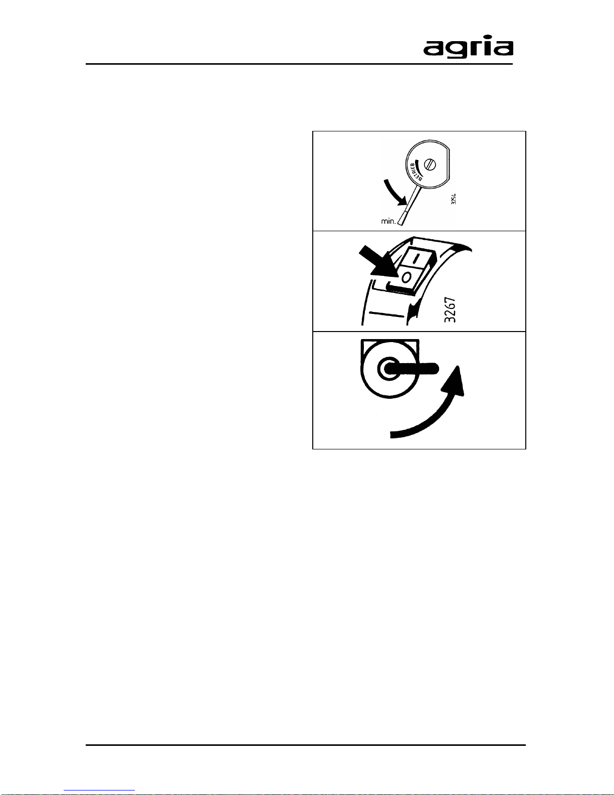
Switching off Engine
l
Move speed control lever to idling gas
position and let engine run idle for
approx.1/2 minute.
l
Move engine-off-switch to position “0”.
l
Close fuel tap.
I
Note: The engine-off-switch
(C/3) also serves as emer-
gency off-switch. If necessary ,
bring switch into position “0” to turn engine off.
I
For longer periods of no opera-
tion, do not switch off engine
with engine-off-switch, but close
fuel tap and let engine run until it slowly
comes to a complete stop due to lack of
fuel. This ensures that carburetor is empty
and no resin residue can deposit.
W
Secure power hoe against
unauthorized use – discon-
nect spark-plug connector .
Page 26
26 Power Hoe 6000 Edition 11.98
4. Commissioning and Operation
Hoeing
l
Start the engine as described in “Start-
ing the Engine”.
l
Pull hand clutch lever (C/5).
l
Select proper speed with gear shift
lever (A/3).
For heavier soil and coarse tilling:
– select slow speed “I”.
For lighter soil and medium tilling:
– select medium speed “II”.
For sandy soil and fine tilling:
– select fast speed “III”.
l
Slowly release hand clutch lever while
pressing the throttle – the power hoe
moves forward and hoeing tools start
working.
End of Hoeing
l
Move speed control lever to idling position.
l
Pull hand clutch lever and hold.
l
Move gear shift lever to position “0”
(neutral).
I
Before you actuate the shift
lever, pull hand clutch lever
to stop. Only move the shift le-
ver with your hands.
Change of work-site
l
T urn off the engine.
l
Pull hand clutch lever.
l
T urn off hoeing drive (B/19) (position
“0”).
l
If present, fold front support wheel into
travel direction.
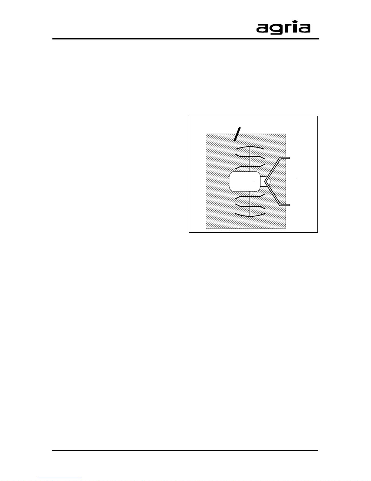
Hazardous area
W
Staying in the hazardous area
of the power hoe is not permitted when the power hoe is
being started or in operation.
W
Never leave the operator’s
position at the steering handle while the machine is at
work.
During all operation with the power
hoe, especially when turning, the
operator must keep at a safe distance
as defined by the steering handle.
Do not clean hoeing tools with the engine running. Switch off the engine
and remove spark plug connector .
If clogging occurs, turn off the engine
and clean the attachment with an appropriate tool (wooden stick).
4227
Hazardous area
Page 27
Edition 11.98 Power Hoe 6000 27
5. Maintenance
0.6 mm ca. 20 Nm
Oil bath air filter
Oil level
Apart from adhering to operating instructions for power hoe, it is also important to
observe the following maintenance
instructions.
W
Warning: Only do maintenance work with the engine
turned off and spark plug connector removed. Always wear safety
gloves, when working on hoeing tools.
Engine
The oil contained in the fuel mixture lubricates the 2-stroke-engine. Therefore,
there is no engine oil filling opening.
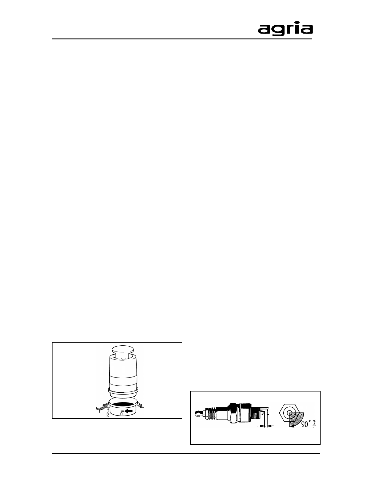
Oil Bath Air Filter
Change oil in oil bath air filter (A/8) after
every 25 operating hours or at least after
3 months. In case of heavy dust
occurence, clean after a few hours –
check for proper condition frequently .
l
Clean air filter and outside surround-
ing parts.
l
Open closing bow and remove oil pot.
l
Remove old oil (dispose of properly)
and clean oil pot.
l
Fill oil pot with engine oil up to oil level
mark (not higher) and re-fit oil pot onto
filter – ensure pot fits tight.
l
After repeated oil change or excessive
dirt in the filter remove the oil pot and
unscrew oil bath air filter. Dip filter into
diesel fuel several times and rinse
thoroughly . Spin dry. Screw air filter back
into place and fill cleaned filter pot with
fresh engine oil. Then re-fit filter pot.
Never wash air filter in petrol, water,
lye or hot liquids.
Cleaning the Cooling System
After operation for an extended period of
time, clogging of plants and dust may
occur in the cooling system. Sustained
operation with the cooling system
clogged lets the engine heat up and
causes damage.
l
Always check cooling-air screen
(B/31) and remove dirt and plant trash
sucked in.
l
Remove fan case at least once per
year, preferably before the season starts,
and clean cooling fins on cylinder and
cylinder head, clean guiding plates and
cooling-air screen, both serving for good
air circulation. For this purpose, contact
your professional agria workshop.
Cleaning Spark Plug and
Setting Spark Plug Gap
After every 50 operating hours
l
remove soot from spark plug electrodes with a steel brush,
l
check the gap between electrodes and
set to 0.6 mm.
Exchange spark plug after approx. 100
hours of operation.
Page 28
28 Power Hoe 6000 Edition 11.98
5. Maintenance
Fuel System
l
Each time you maintain the machine,
check fuel hose, fuel tank, and carburetor
for leakages. Repair , if necessary .
l
Replace fuel hoses after every 2
years, immediately exchange leaking
hoses.
l
Always fill correct stoichiometric ratio
of fuel.
l
If engine received too much fuel
(flooded), move speed control lever to
“max” and crank engine with recoil starter
until engine starts. Or remove spark plug
and clean and dry. With spark plug
removed, crank engine a few times with
recoil starter. Screw spark plug back in
and re-start engine.
Cleaning Cylinder Head
After every 400 hours of operation take
off cylinder head and remove carbon
deposits on cylinder head and exhaust
tunnel with a steel brush. Afterwards,
clean with soft paint brush. Exchange
head gasket and reassemble to cylinder
head. Tighten cylinder head screws in
turn at 22 Nm. For this purpose, contact
your professional agria workshop.
Carburetor Settings
Changes in fuel, temperature, height or
strain can require slight re-adjustments
of carburetor settings. Only let engine run
with air filter and air filter pot mounted.
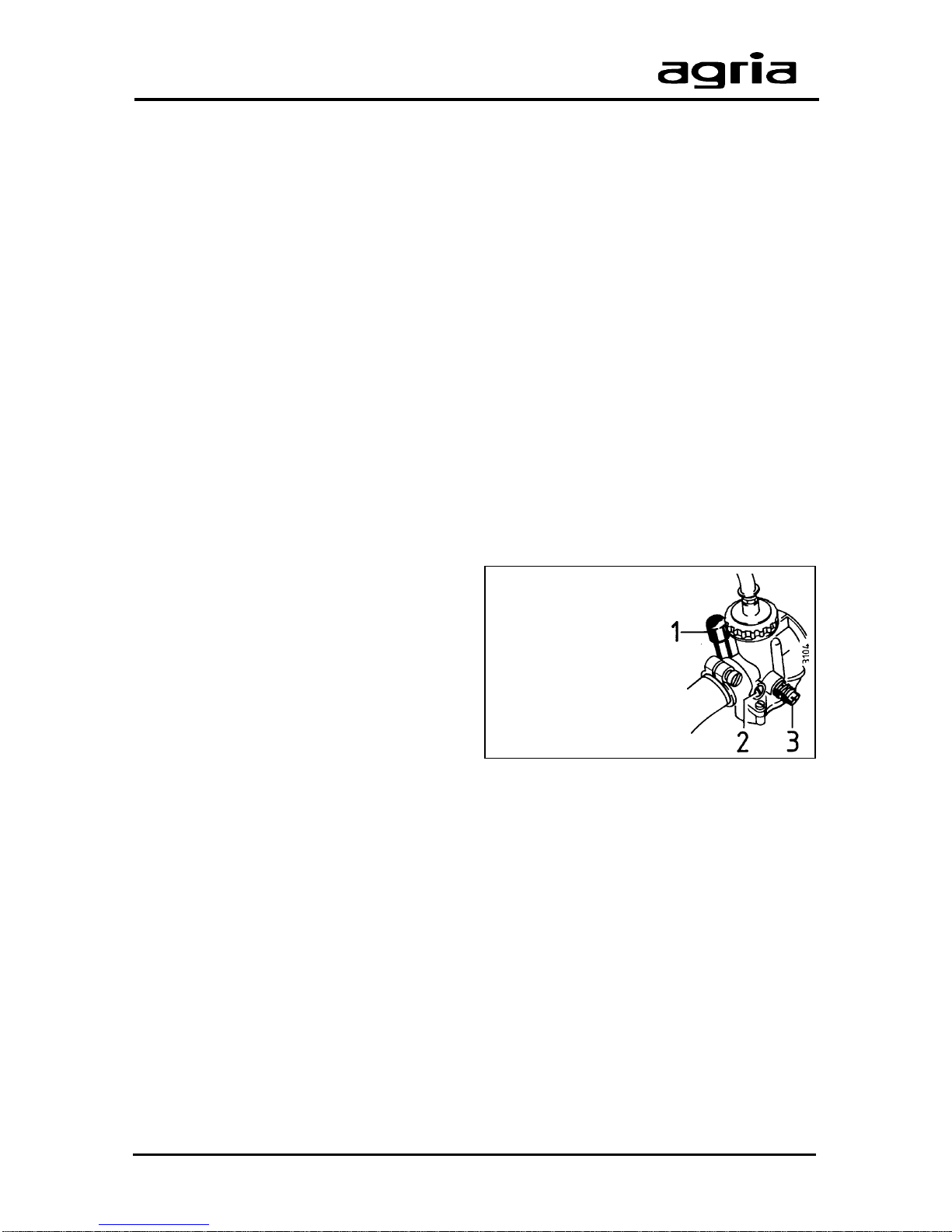
Idling Speed
Always ensure that idling engine speed
is adjusted correctly . At low speeds, the
engine is supposed to run smoothly , with
speed control lever at stop in idling speed.
For basic tuning, adjust the slide valve
adjusting screw (3) on the slide
carburetor . For this purpose, set the throttle control cable free of play by turning
the adjusting screw on carburetor.
For fine tuning, adjust the air control
screw (2). Adjust only while the engine is
still warm from operation (also refer to
“Specifications”). For these adjust-
ments, contact your professional agria
workshop.
Exhaust
l
Constantly check exhaust system
(A/12) for plant trash and clean, if necessary . Otherwise
W
danger of fire!
Check before each operation.
l
Check exhaust after every 200 oper-
ating hours for oil carbon and, if necessary , clean or burn out.
For this purpose, contact your professional agria workshop.
1 Carburetor –
tickler
2 Air control
screw
3 Slide valve
adjusting
screw
Page 29
Edition 11.98 Power Hoe 6000 29
5. Maintenance
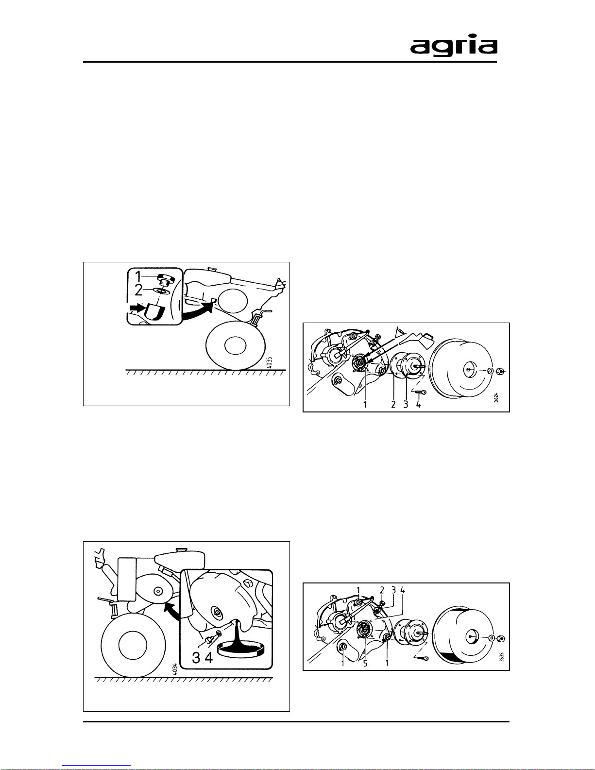
3 Drain plug
4 O-ring
Manual Gearbox
Check the transmission oil level in the
gearbox before you start up the machine
and repeat checks at intervals of 25
operating hours.
l
Park the machine on level ground (see
illustration).
The oil level is visible in the opening
(B/28) after the Allen head screw has
been removed. T op up transmission oil, if
necessary.
Change transmission oil after the first
25 operating hours and then at intervals
of 50 operating hours. Ensure oil filler plug
(B/28), drain plug and the surrounding
parts are absolutely clean to prevent any
ingress of dirt.
For oil filling quantity and quality, see
”Specifications”.
Chain Drive
The chain drive is filled with transmission
oil.
Refilling is not necessary as long as no
lubricant leaks are spotted on the
housings and their seals.
Checking Lubricants
l
Open the cover of the housing (A/21).
l
Crank the hoeing shaft at least 6 rotations. Lubrication is fine, if the chains are
wet with transmission oil (visual check).
T op up transmission oil, if necessary .
Chain Tension
The wheel drive chain should neither be
tight nor too slack.
l
Undo the 3 attachment bolts (1) and
the locking nut (3).
l
Set the chain tension via the hex head
bolt (2).
l
Retighten locking nut (3) and attachment nuts (1).
1 Plug
2 O-ring
Oil level
Page 30
30 Power Hoe 6000 Edition 11.98
5. Maintenance
Hoeing drive
The hoeing drive is filled with semi-fluid
grease. Refilling is not necessary, if no
leaks are visible on the housings and their
seals.
Lubrication inspection
l
Open the plug (A/12)
l
Crank the hoeing shaft at least 6 rotations. Lubrication is fine, if the chains
are wet with transmission oil (visual inspection). T op up transmission grease, if
necessary.
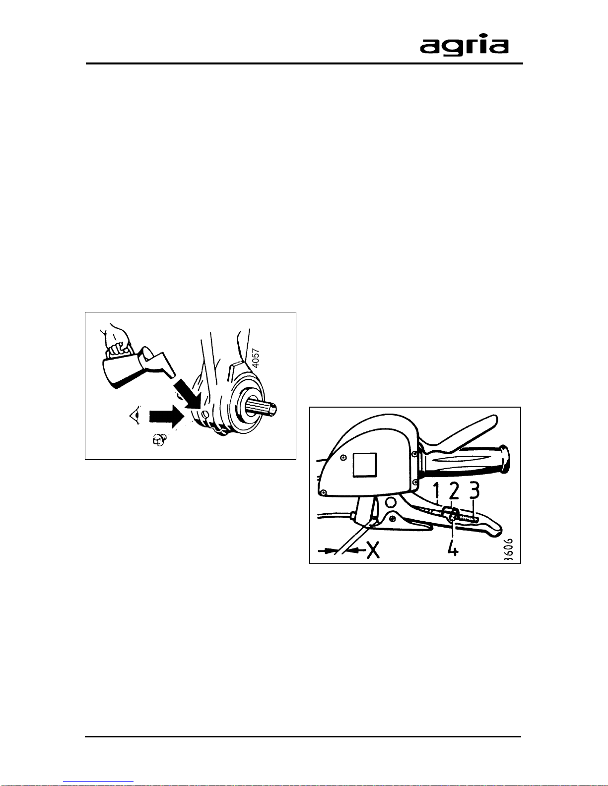
Adjustments on Levers
Check play or settings each time before
you operate the machine and readjust
them, if necessary (in particular during
breaking-in after starting up the machine
and after replacing the clutch disks).
l
Remove retaining spring (2) with a
screw driver or a similar tool.
l
Use set pin (4) to press the cable end
(3) out of the bracket in the lever.
l
Adjust the set pin (4) to a play of X.
(Screw set pin in to reduce the play , screw
it out to increase the play).
l
For inspection, hook the cable end
back into the bracket, using the set pin.
l
Fit retaining spring (2).
Clutch lever:
X = 3–5 mm (Clutch play)
Page 31
Edition 11.98 Power Hoe 6000 31
Dead Stop
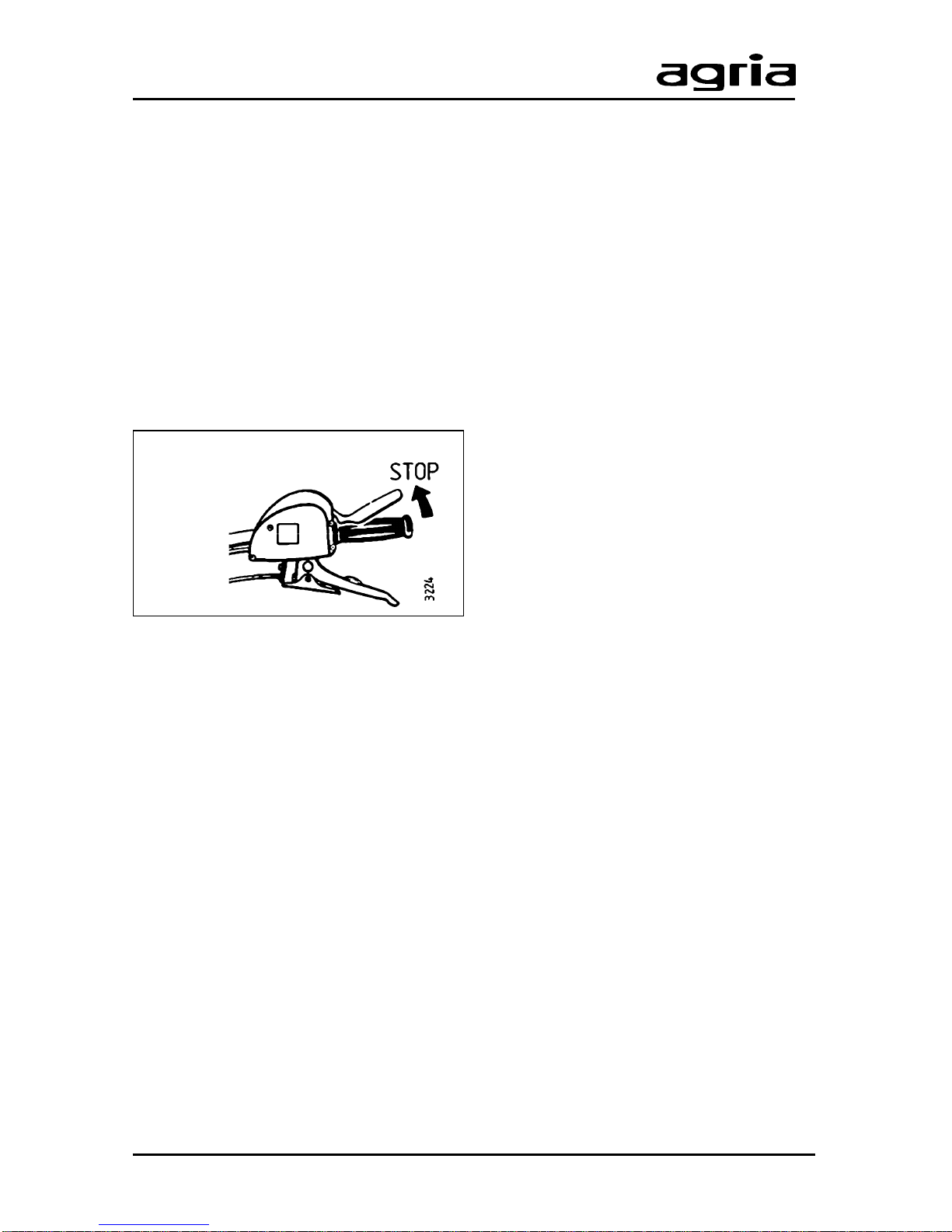
Check the dead stop function each time
you maintain the machine.
l
The engine must automatically come
to a stop upon release of the lever (C/4)
and clutch engagement.
l
Inspect all electric lines and connections and replace them if necessary .
For this purpose contact your agria
workshop.
Drive-Wheel
l
Check the tyre pressure (1.2 bar) at
regular intervals.
l
Fit the wheels with pointed parts of
lugs showing in travelling direction
(wheels seen from above) to provide full
tractive power.
l
Retighten wheel nuts and locking bolts
at 100 Nm on the hubs each time you
maintain and service the machine.
5. Maintenance
Stop position
General
l
Watch out for fuel and oil leaks, and
remove them if necessary .
l
Check nuts and bolts regularly for tight
fit and tighten them if necessary .
l
Grease all gliding and moving parts
(e.g. speed control lever, hand lever
bearing, etc.) slightly with Bio-lubrication
grease and Bio-lubrication oil.
Cleaning
After each cleaning (washing with water,
especially with a pressure washer)
lubricate all lubrication points, oil the
machine, and let the power hoe run for a
short time to press the water out.
Apply grease generously and leave a
grease ring around the bearings to prevent water, plant sap, and dirt from penetrating.
Engine
Clean the engine only with a cloth. A void
spraying with strong jets of water because water might leak into ignition and
fuel system, causing malfunctions.
Page 32

32 Power Hoe 6000 Edition 11.98
5. Maintenance
Storage
For longer periods of no operation
prepare the machine for storage. Proceed as follows:
a) Clean thoroughly
Repair paint coat, lubricate machine and
attachment and operate for a short time.
Then spray all shining parts, in particular
hoeing tools, with Bio-slushing oil.
b) Engine preservation
l
Drain fuel completely and let the engine run until it comes to stop due to lack
of fuel or add fuel stabilizer (agria No. 673
50).
Method: Fill fuel tank, add anti-corrosive
and stabilizing liquid (amount “ON”
stabilizes 4l of fuel). Let engine run for
approx. 1 minute. (Observe enclosed
instructions).
l
Fill a tea-spoon (approx. 0.03l) of
engine oil into spark plug opening. Slowly
crank the engine.
l
Set the piston to compression with the
recoil starter to keep the valves closed.
l
Slowly crank the engine every 2–3
week (spark-plug connector is removed).
Then set the piston to compression again.
W
Warning! Keep anti-corrosive
and stabilizer out of reach of
children at all times. Do not
inhale vapours! In case of sickness
and vomiting see a doctor immediately! In case of eye contact with liquids, rinse eyes thoroughly.
c) Drive-wheels
Support drive-wheels in such a way that
tyres have no ground contact. Pneumatic
tyres are quickly destroyed, if left parked
under load and unsupported.
d) Storing the machine
Do not park the machine in humid
rooms, in rooms where fertilizer is stored,
in stables or adjacent rooms because of
severe corrosion.
e) Protecting the machine
Protect machine with cloth or a similar
cover.
Page 33
Edition 11.98 Power Hoe 6000 33
agria Order No.
Lubricants and Anti-Corrosive Agents
690 35 Bio-lubrication grease cartridge 400g
690 36 Bio-Slushing oil bottle 500ml
673 50 Fuel stabilizer bottle 125ml
Please read and observe enclosed instructions!
Varnishes
181 03 Spray varnish birch-green spray tin 400ml
712 98 Spray varnish red, RAL 2002 spray tin 400ml
509 68 Spray varnish black spray tin 400ml
Wear Parts
304 40 Spark plug M 10 A
009 16 O-ring Ø16x22x2
for gearbox filling opening
009 44 O-ring Ø8x1 1x1
for gearbox drain opening
102 53 Cylinder head gasket
241 92 Chain housing seal – top, internal
256 45 Chain housing seal top, external
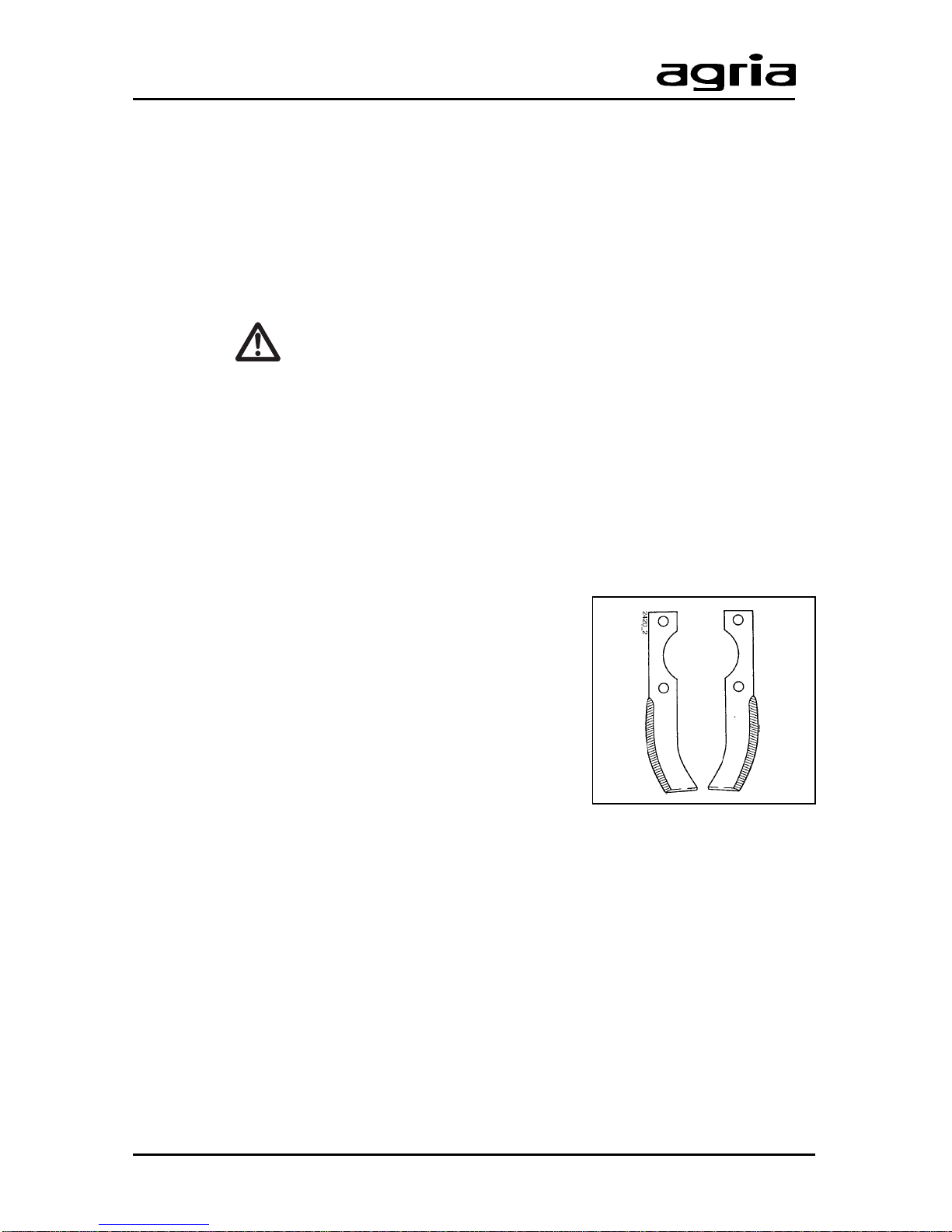
172 22 Hoeing tine, left
172 23 Hoeing tine, right
Spare Parts
997 127 Power Hoe 6000
997 050 agria Engine
Lubricants, V arnishes, Wear Parts
left
right
Page 34
34 Power Hoe 6000 Edition 11.98
6. Troubleshooting
W
Observe safety instructions! Have all serious malfunctions on the machine or engine repaired by your
agria workshop. They have the proper tools. Improper repairs can only add to the damage.
Problem Possible cause Remedy Page
Engine -Spark plug connector not connected Connect spark plug connector
does not start - Engine-off-switch is set to 0 Set engine-off-switch to I 24
-Dead stop lever is not set Set dead stop lever to start position 24
to start position
-Fuel tank empty or poor fuel Fill fresh fuel 23
-Fuel line clogged Clean fuel line 28
-Defective spark plug Clean, adjust or exchange spark plug 27
-Engine too much fuel Dry and adjust spark plug and
(flooded engine) start at full throttle
-Engine-off-line defective Check line and connections ¬
-Inleaked air due to loose caburetor Tighten attachment bolts
Misfirings in -Loose ignition cable Firmly connect spark plug connector to
engine spark plug, fix ignition cable retaining device
-Clogged fuel line Clean fuel line, ¬
or poor fuel fill fresh fuel 23
-Vent opening in fuel tank cap clogged Exchange fuel tank cap
-Water or dirt in fuel system Drain fuel and fill fresh fuel
-Air filter clogged Clean air filter or exchange 27
-Carburetor misadjusted Re-adjust carburetor ¬ 28
Excessive - Impaired cooling Clean cooling fan grid,
temperature clean internal cooling ribs 27
in engine -Air filter clogged Clean air filter 27
-Carburetor misadjusted Re-adjust carburetor ¬ 28
Misfirings -Short firing intervals Adjust spark plug 27
in engine -Incorrect idle mixture Adjust carburetor ¬ 28
at high speeds
Engine -Firing interval too long, Adjust or replace spark plug 27
frequently defective spark plug
stalls -Carburetor misadjusted Re-adjust carburetor ¬ 28
in idle -Air filter clogged Clean air filter 27
Engine -Defective engine-stop-line, Check line and connection,
does not stop earth missing check earth contact
when set
to stop
Page 35
Edition 11.98 Power Hoe 6000 35
6. Troubleshooting
Problem Possible cause Remedy Page
Engine -Loose cylinder head or Tighten cylinder head, ¬ 28
output too low damaged sealing exchange sealing
-Poor compression Have engine checked ¬
Clutch does -Hand clutch lever misadjusted Adjust clutch free play 30
not decouple
Clutch slips -Hand clutch lever misadjusted Adjust clutch free play 30
-Worn out clutch linings Exchange clutch linings ¬
Excessive - Loosened bolts Tighten attachment bolts 31
vibration
¬ = For this purpose contact your agria workshop.
Page 36
36 Power Hoe 6000 Edition 11.98
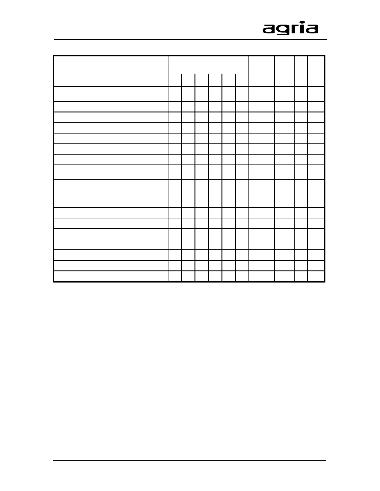
7. Inspection and Maintenance Chart
A = Each time before you take up operation
B = After each cleaning
K = Checks and maintenance to be executed by operator
W = Maintenance to be executed by professional workshop
F = Maintenance should be carried out by your agria workshop
* = after 2 years
After operating hours
A 5 25 50 100 200
Clean engine,
check bolts and nuts
K31
Check air filter
K27
Air filter – oil change, earlier, if require d
KK27
Clean air filter t otally, earlier, if required
W 27
Repla c e f u el hoses
W* 28
Clean cylinder head
F28
Clean cooling- air s c r een
K27
Clean guide plat es, cooling fins –
earlier, if re
q
uired
FF27
Clean spark plug,
set spark plug gap
W27
Repla c e s park plug
K27
Check safety switch function
K31
Check oil level in manual gearbox
K29
First oil change in manual gearbox
W29
subsequent oil changes
WW29
Check lubricati on of chain and hoeing drive
W40
Lubricate all gliding parts
KK31
Check clutch free play
K30
min. 3
months
min.
yearly B page
Page 37
Edition 11.98 Power Hoe 6000 37
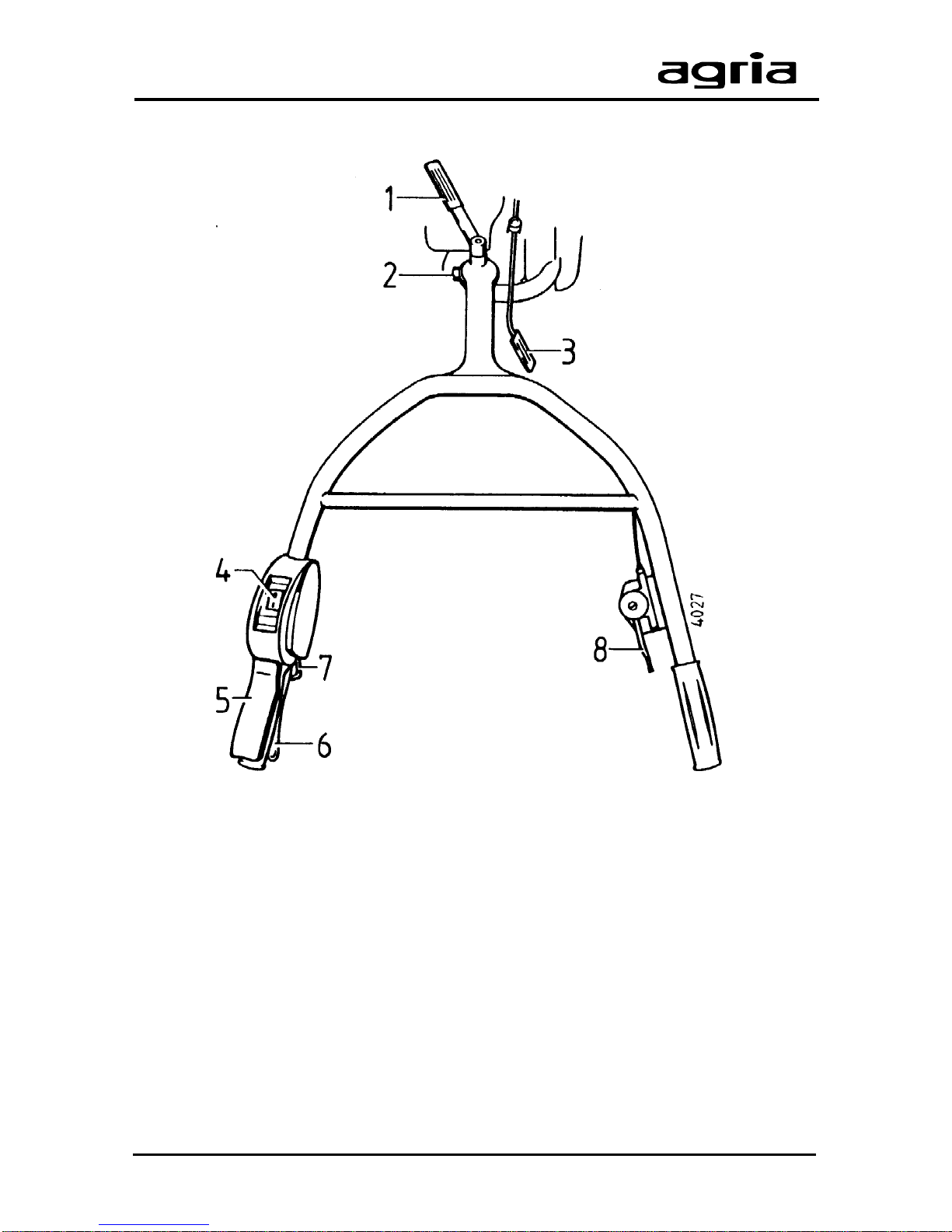
Figure C
1 Hex head bolt for steering handle height adjustment
2 T ommy screw for steering handle side adjustment
3 Gearshift lever
4 Engine shut-off switch
5 Dead stop lever
6 Clutch lever
7 Pawl
8 Speed control lever
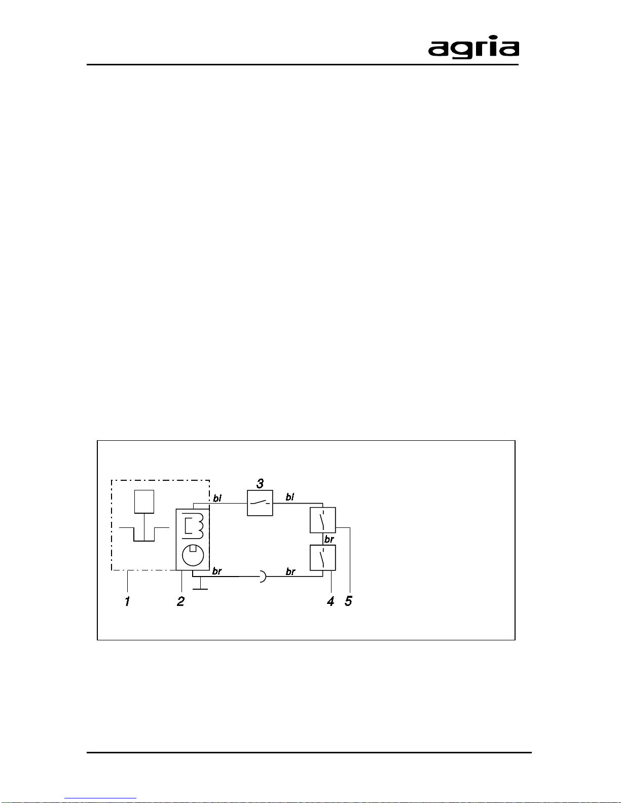
Designation of Parts,
Electrical Wiring Diagram
1 Engine
2 Magnet ignition system
3 Engine speed delimiter
4 Switch in dead stop lever
5 Switch in clutch lever
bl = blue
br = brown
Electrical Wiring Diagram
Page 38
38 Power Hoe 6000 Edition 11.98
Designation of Parts
C
Page 39
Edition 11.98 Power Hoe 6000 39
EC Conformity Declaration
in accordance with the EC directive machinery 98/37/EC
We,
agria-Werke, GmbH
D-74215 Möckmühl/Württ.
herewith declare in sole responsibility that the product
Power Hoe, Type 6000
to which this declaration refers, corresponds to
the standard fundamental safety and health requirements
as stipulated in EC directive machinery 98/37/EC
and EMC directive 89/336/EC.
The following harmonized standards have been applied:
EN 709
Möckmühl, 20th May 1997
Gregor Czaja Dipl. Ing. Thomas Ilchmann
Head, Qualitity Control Head, Research and Development
Page 40
Contact your authorised agria dealer for service and prompt delivery of spare parts
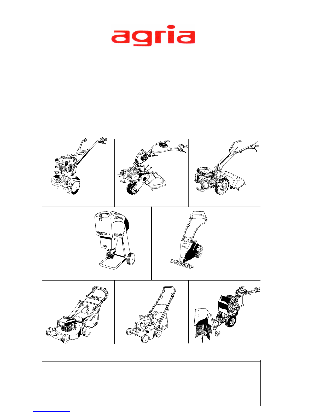
The Winning Team
Power hoes One-wheel hoes Hobby two-wheelers
AllShredd Cutterbar mowers
Lawn mowers Verticutters All-purpose machines
agria-Werke GmbH
D-74215 Möckmühl/Württ.
Phone 0049 6298 39-0
Fax 0049 6298 39-111
e-mail: [email protected]
Internet: http://www.agria.de
Horticultural MachineryHorticultural Machinery
Horticultural MachineryHorticultural Machinery
Horticultural Machinery
 Loading...