


Version:20160722

2
Material Applications:
* Automotive renish
* Architectural
* Marine
* Industrial
* Aerospace
* Wood
* Plastic
On-off switch
Speed control knob
Carry HandlePattern adjuster
Vent tube
Air cap
Needle & Nozzle
Trigger
Cup Latch
Paint cup
Quick-release hose
coupling-Gun
Filter compartment
Fluid flow control knob
Quick-release hose
coupling-Turbine
Hose
Voltage See machine nameplate
Power Input 1400W
Turbine 3 stage
Airow 2800 l/min
Max Working Pressure 0.41 bar (6 psi)
Turbine Dimensions (LxWxH) 325mm x 250mm x 325mm
Net Weight 8.5 kg ( 18.7 Lbs)

3
GENERAL SAFETY RULES
WARNING! Read and understand all
instructions. Failure to follow all instructions
listed below may result in electric shock, re
and / or serious personal injury. The term “power
tool” in all of the warnings listed below refers to
your mains-operated (corded) power tool.
SAVE THESE INSTRUCTIONS.
WORK AREA
1. Keep your work area clean and well lit.
Cluttered benches and dark areas invite
accidents.
2. Do not operate power tools in explosive
atmospheres, such as in the presence of
flammable liquid, gases, or dust. Power
tools create sparks which may ignite the dust
or fumes.
3. Keep bystanders, children, and visitors
away while operating a power tool.
Distractions can cause you to lose control.
ELECTRICAL SAFETY
1. Power tool plugs must match the outlet.
Never modify the plug in any way. Do
not use any adapter plugs with earthed
(grounded) power tools. Unmodified plugs
and matching outlets will reduce the risk of
electric shock.
2. Grounded tools must be plugged into an
outlet properly installed and grounded in
accordance with all codes and ordinances.
Never remove the grounding prong or
modify the plug in any way. Do not use
any adaptor plugs. Check with a qualified
electrician if you are in doubt as to whether
the outlet is properly grounded. If the tools
should electrically malfunction or break down,
grounding provides a low resistance path to
carry electricity away from the user.
3. Avoid body contact with grounded
surfaces such as pipes, radiators, ranges
and refrigerators. There is an increased risk
of electric shock if your body is earthed or
grounded.
4. Do not expose power tools to rain or wet
conditions. Water entering a power tool will
increase the risk of electric shock.
5. Do not abuse the cord. Never use the cord
for carrying, pulling or unplugging the
power tool. Keep the cord away from heat,
oil, sharp edges or moving parts. Replace
damaged cords immediately. Damaged or
entangled cords increase the risk of electric
shock.
6. When operating a power tool outdoors,
use an outdoor extension cord suitable
for outdoor use. Use of a cord suitable for
outdoor use reduces the risk of electric shock.
PERSONAL SAFETY
1. Stay alert, watch what you are doing and
use common sense when operating a power
tool. Do not use tool while you are tired or
under the influence of drugs, alcohol, or
medication. A moment of inattention while
operating power tools may result in serious
personal injury.
2. Use safety equipment. Always wear eye
protection. Safety equipment such as dust
mask, non-skid safety shoes, hard hat, or
hearing protection used for appropriate
conditions will reduce personal injuries.
3. Avoid accidental starting. Ensure the switch
is in the off position before plugging in.
Carrying tools with your nger on the switch
or plugging in tools that have the switch on
invites accidents.
4. Remove adjusting key or wrench before
turning the power tool on. A wrench or a key
left attached to a rotating part of the tool may
result in personal injury.
5. Do not overreach. Keep a proper footing
and balance at all times. This enables better
control of the power tool in unexpected

4
situations.
6. Dress properly. Do not wear loose clothing
or jewellery. Keep your hair, clothing and
gloves away from moving parts. Loose
clothes, jewellery or long hair can be caught in
moving parts.
7. If devices are provided for the connection
of dust extraction and collection facilities,
ensure these are connected and properly
used. Use of these devices can reduce dust-
related hazards.
POWER TOOL USE AND CARE
1. Do not force the power tool. Use the correct
power tool for your application. The correct
power tool will do the job better and safer at
the rate for which it was designed.
2. Do not use the power tool if the switch
does not turn it on and off. Any power tool
that cannot be controlled with the switch is
dangerous and must be repaired.
3. Disconnect the plug from the power source
before making any adjustments, changing
accessories, or storing power tools. Such
preventive safety measures reduce the risk of
starting the power tool accidentally.
4. Store idle tools out of reach of children and
do not allow persons unfamiliar with the
power tool or these instructions to operate
the power tool. Power tools are dangerous in
the hands of untrained users.
5. Maintain power tools. Check for
misalignment or binding of moving parts,
breakage of parts and any other condition
that may aect the power tool’s operation.
If damaged, have the power tool repaired
before use. Many accidents are caused by
poorly maintained power tools.
6. Keep cutting tools sharp and clean. Properly
maintained cutting tools with sharp cutting
edges are less likely to bind and are easier to
control.
7. Use the power tool, accessories and
tool bits etc., in accordance with these
instructions and in the manner intended
for the particular type of power tool, taking
into account the working conditions and
the work to be performed. Use of the power
tool for operations different from intended
could result in a hazardous situation.
SERVICE
Have your power tool serviced by a qualified
repair person using only identical replacement
parts. This will ensure that the safety of the power
tool is maintained.
If the supply cord of this power tool is damaged
it must be replaced by a specially prepared cord
available through the service organization.
Symbols used in this manual
V…….......volts
A…….......amperes
Hz……......hertz
W……......watt
~………....alternating current
n
0
………..no load speed
min
-1
….....revolutions or reciprocation
per minute
......warning of general danger
.….class II tool
.…with electrical earth
.......read these instructions
......always wear eye protection
......always wear a dust mask.
.....always wear hearing protection
.....wear safety-approved hard hat
do not dispose of electric tools,
accessories and packaging together
with household waste material

5
SPECIFIC SAFETY RULES FOR HVLP
SPRAYERS
OBSERVE ALL WARNINGS!
WARNING: Do not use guns for spraying
ammable materials.
WARNING: Be aware of any hazards presented
by the material being sprayed, and consult
the markings on the material container or the
information supplied by the manufacturer of
the material to be sprayed.
WARNING: Do not spray any material where the
hazard is not known.
WARNING: Do not clean guns with flammable
solvents with a ash-point below 55°C.
NOTE: A non-ammable solvent is here dened
as one which has a ash-point above 55°C.
WARNING: This appliance cannot be used by
children under 18 years old or persons with
reduced physical, sensory or mental capabilities
or lack of experience or knowledge of the safe
operation of the appliance.
WARNING: Children may not play with this
appliance.
WARNING: Cleaning and user maintenance shall
not be made by children.
WARNING: This appliance shall be disconnected
from its power source during service and when
replacing parts. The plug must remain removed,
and must be removed in such a way that an
operator can check from any of the points to
which he has access that the plug remains
removed.
This equipment is for professional use only.
WARNING: FIRE AND EXPLOSION HAZARD.
Take all precautions to avoid sources of sparks
and ignition when spraying. Keep the machine
at least 8 meters away from the spraying
operation.
Wear Protective Equipment At All Times.
Always use a respirator, eye protection and
protective clothing and gloves.
CAUTION:
• Do not use the sprayer with flammable
paint.
• Do not use guns for spraying flammable
materials.
• Do not clean guns with flammable
solvents.
• Beware of any hazards presented by
the material being sprayed and consult
the markings on the container or the
information supplied by the manufacturer
of the material to be sprayed, including
requirements for the use of personal
protective equipment.
• Do not spray any material where the
hazard is not known
The appliance is not to be used by children or
persons with reduced physical, sensory or mental
capabilities, or lack of experience and knowledge,
unless they have been given supervision or
instruction and children being supervised not to
play with the appliance.
EXPLOSION RISK FROM
HALOGENATED HYDROCARBON
SOLVENTS
Never use halogenated hydrocarbon solvents in
this machine. Contact with aluminum parts may
cause an explosion. Some of the most common
of these solvents are: Carbontetrachloride,
Chlorobenzene, Dichloroethane, Dichloroethyl
Ether, Ethylbromide, Ethylchloride, &

6
Tethrachloethane.
PREVENT STATIC SPARKING FIRE/
EXPLOSIONS
Vapors created when spraying can be ignited by
sparks. To reduce the risk of re, always locate the
turbine at least 20 feet (6 m.) away from spray area.
Do not plug in or unplug any electrical cords in the
spray area. Doing so can cause sparks which can
ignite any vapors still in the air. Follow the coating
& solvent manufacturers safety warnings and
precautions.
WARNING: Keep the turbine away from areas
with hazardous concentrations of flammable
vapors. NEVER operate with the turbine inside a
spray booth.
• NEVER point the spray gun at anyone or any
part of the body.
• NEVER put your hand or ngers over the uid
nozzle.
• NEVER try to stop or deect leaks with your
hand, body, or rag.
• NEVER alter equipment in any manner.
• NEVER smoke while in spraying area.
• NEVER spray highly ammable materials.
• NEVER use around children.
• NEVER allow another person to use sprayer
unless he is thoroughly instructed on its safe
use and given this operator’s manual to read.
• ALWAYS wear a spray mask/respirator, gloves
and protective eye wear while spraying.
• ALWAYS ensure re extinguishing equipment
is readily available and properly maintained.
ALWAYS INSPECT SPRAYING AREA
• Keep the spraying area free from obstructions.
• Make sure the spraying area has good
ventilation to safely remove vapors and mists.
• NEVER keep ammable material in spraying
area.
• NEVER spray in vicinity of open flame or
other sources of ignition.
• The spraying area must be at least 20 ft. away
from spray unit.
TOXIC FLUID HAZARD
• Hazardous fluid or toxic fumes can cause
serious injury or death if splashed in eyes
or on skin, inhaled or swallowed. Know the
hazards of the fluid you are using. Store
& dispose of hazardous fluid according
to manufacturer, local, state & national
guidelines.
• ALWAYS wear protective eyewear, gloves,
clothing and respirator as recommended by
uid manufacturer.
HOSES
Do not allow kinking or crushing of hoses or
allow it to vibrate against rough, sharp or hot
surfaces.
• NEVER use a damaged hose. Before each use,
check entire hose for cuts, leaks, abrasions,
or bulging. If any of these conditions exist,
replace the hose immediately.
GROUNDING
• Ground the sprayer & other components
in the system to reduce the risk of static
sparking, re or explosion which can result in
serious bodily injury and property damage.
For detailed instructions on how to ground,
check your local electrical code.
• ALWAYS ensure switch is in OFF position
before plugging unit in.

7
ALWAYS GROUND ALL OF THESE
COMPONENTS
1. Turbine: plug the power supply cord, or
extension cord, each equipped with an
undamaged three-prong plug, into a properly
grounded outlet. DO NOT USE AN ADAPTER.
Use only a 3 wire extension cord that has a
grounding plug, and a receptacle that will
accept the grounding plug on the product.
Make sure your extension cord is in good
condition. When using an extension cord, be
sure to use one heavy enough to carry the
current your product will draw. If in doubt,
use the next heavier gauge.
2. Hose: use only grounded hoses.
3. Spray gun: grounding is obtained through
connection to a properly grounded hose and
turbine.
• NEVER use cleaning solvents with ash points
below 140 degrees F. Some of these are:
acetone, benzene, ether, gasoline, naptha.
Consult your supplier to be sure.
FUNCTIONAL DESCRIPTION
This HVLP (High Volume, Low Pressure) turbine
uses a controlled cone of high volume, low
pressure air created by the gun which can spray
with very little waste and overspray. This high
efficiency delivery absolutely minimizes air
pollution emissions associated with paint spraying.
Media which are traditionally sprayed by high
pressure compressor driven paint sprayers can be
sprayed by this new technology. The paint drying
times are even quicker because the air from the
turbine is naturally warm.
UNPACKING AND ASSEMBLY
1. Remove all parts from the carton.
2. Check for any damage.
3. Attach the hose to the turbine.
4. Attach the hose to the gun.
PREPARATION
Prepare the paint solution
Strain the paint and all other media components
before you spray
Remember to use a slower drying reducer than you
would normally use with a conventional air sprayer.
The warm air of the turbine causes faster drying
times. Usually one step slower will do.
For Automotive finishes, reduce and catalyze
according to the paint manufacturer’s instructions,
just remember to use one step slower reducer.
For Industrial finishes, reduce and catalyze
according to the paint manufacturer’s instructions.
If there are no reduction instructions, add reducer
step by step untill the proper consistency is found.
Droplets off the stir stick should be about one
second apart.
WARNING:
Universal motors, like the one used in this
turbine, by their nature create sparks at the
commutator. Whenever spraying flammable
media, keep the turbine at least 6 meters (20
feet) away from the spraying area.
OPERATION
1. Ensure that all protective clothing and safety
devices are in place and Fill the paint cup.
2. Allow the turbine to warm up by turning it on
for a few minutes before beginning spraying.
(This will make adjusting the gun easier).
3. Adjust the gun on a test surface, then begin
spraying

8
CHOOSING FLUID SETS
The fluid set includes a Needle, a Nozzle and an
Air Cap. These parts are a matched set. Do not mix
parts from other sizes. The standard uid set which
comes with the gun is a 1.3mm, which will work
well for most applications.
Different sizes of fluid set will give different flow
rates. A more viscous uid will need a larger size. A
thinner uid will need a smaller size.
TO CHANGE TO A DIFFERENT FLUID
SET
1. Loosen and remove the Air Cap.
2. Unscrew and remove the Nozzle. Whenever
tightening or loosening the nozzle, pull the
trigger all the way and hold it to prevent
damage to the seating surfaces of the Needle
and Nozzle.
3. Unscrew the Fluid Control Knob all the way
and remove it, together with the spring.
4. Pull out the Needle through the back of the
Gun.
5. Replacement is the opposite of removal.
ADJUSTING THE GUN
The gun will normally need to be adjusted before
each use. This is similar to tuning a musical
instrument before playing it.
1. First adjust the Fluid Flow Control Knob. Turn
anti-clockwise for more fluid, clockwise for
less fluid. A good starting point would be
about 2-1/2 turns out from closed.
2. Test the spray pattern and atomization on a
test piece. Hold about 20cm (8 inches) away.
Turn the Pattern Adjustor knob for the desired
pattern.
3. Adjust the Speed Control knob on the turbine
to control the air volume. Generally, it is best
to use the minimum air volume which will
achieve satisfactory atomization. The point
is to get the droplet size as small as possible
while still having the desired coverage.Too
much air will only cause overspray mist and
waste paint. If the Speed Control knob is at
maximum and the atomization is still not
satisfactory, the atomization can also be
controlled by thinning the paint. One can also
use a different fluid set ( the needle, nozzle
and air cap).
Fluid flow control knob
Pattern adjuster
On-off switch
Speed control knob
Air cap Nozzle
Trigger
Retaining ring
9
CLEAN-UP
Always clean the gun at the end of the day or
between colors
1. Using a rag moistened with a compatible
solvent, clean the cup and the outside of the
gun.
2. Remove the Air Cap, Baffle and Nozzle and
clean with a cleaning brush. Take care to
avoid damage to the air cap holes.
3. Remove the needle and clean. Clean the paint
carrying orifices of the gun. Do not allow
solvent to enter the air carrying orifices of
the gun. Therefore point the gun down while
cleaning the paint orces.
Never soak the entire gun in solvent.
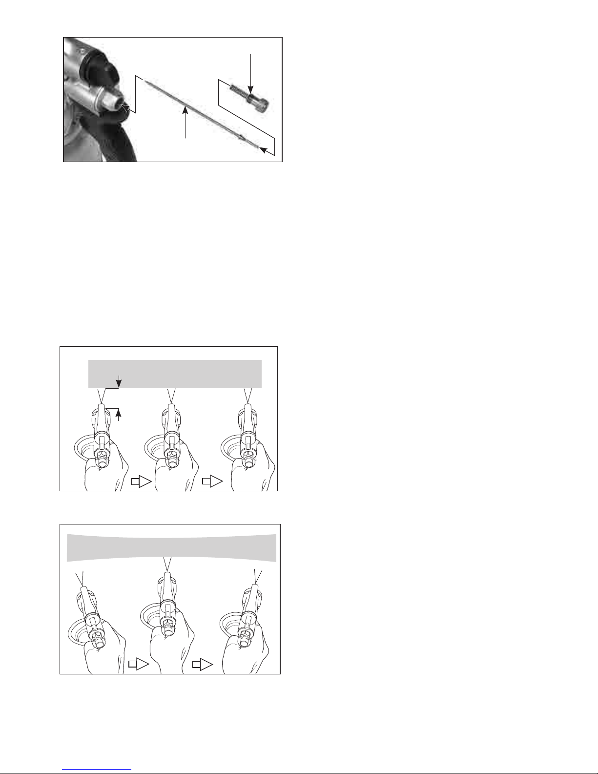
USING OPTIONAL REMOTE PRESSURE
POTS
The standard set-up of this gun is as an HVLP
turbine cup-feed gun. It is also possible to use
this gun and turbine with a remote pressure pot
(pressure feed set-up). All that is necessary is to
convert the gun. To convert:
1. Use an appropriate wrench to loosen the nut
to remove the paint cup.
2. Connect the hose from the pressure pot.
3. Use an appropriate wrench to unscrew the
nipple for the vent tube from the gun body.
4. Use a bolt with the correct thread to plug the
hole from the nipple.
PRESSURE RELIEF PROCEDURE
When using a pressure pot, the pot must always
be relieved of pressure before opening. To relieve
pressure:
1. Shut o the air supply to the pot.
2. Open the pressure relief valve on the pot.
SPRAYING TECHNIQUE
Keep the gun about 150 to 200mm away from the
surface. Do not swing the arm in an arc. Rather,
keep the gun perpendicular to the surface and
move in a parallel motion. Make sure the gun is
already in motion before triggering and release the
trigger while the gun is still in motion. Overlap 50%
with each stroke.
Fluid flow control knob
Needle
6 to 8 in
(150 to 200mm)
RIGHT
WRONG

10
MAINTENANCE
1. Keep the gun clean
2. Keep the inlet lters of the turbine clean.
Entrust repairs to a qualied service technician

11
WIRING

12
HVLP TURBINE EXPLODED VIEW
NO.01~68 G V2.0
20
54
53
52
51
50
30
31
272625
272625
29
29
28
24
31
30
33
32
34
43
44
48
20
36
23
21
20
42
18
13A
15
14
13B
15
14
13B
12
11
09
10
09
08
07
03
04
05
06
16
17
38
37
39
02
01
22
35
49
19
40
41
45
43-2
43-1
64
65
66
67
68-1
68-2
68-3
68-4
68-5
68-5
68-7
68-8
68-9
68A-6
68B-6
68
G

13
HVLP TURBINE PARTS LIST
NO. Parts Name Q'TY
1 HEX NUT-LEFT HAND THREAD M6 1
2 FAN 70 x 6 1
3 MOTOR HOUSING 1
4 BRUSH HOLDER 2
5 CARBON BRUSH 7 x 12 2
6 SCREW M4 x 12 4
7 STATOR 1
8 STATOR SCREW M5 x 60 2
9 BEARING 6200 LLU 2
10 ARMATURE 1
11 MOTOR FRONT COVER 1
12 SPACER-LARGE 1
13A TURBINE IMPELLER 1
13B TURBINE IMPELLER 2
14 EXHAUST HOUSING 2
15 SPACER 2
16 FLAT ALUMINUM WASHER 8 x 23 x 2 1
17 HEX NUT M8 1
18 INTAKE HOUSING 1
19 SOUND DEADENING-MOTOR 10 x 190 x 580 1
20 SCREW M4 x 10 12
21 MOTOR VENT 1
22 SOUND DEADENING-RH 20 x 130 x 140 1
23 CASING-RH 1
24 SCREW M6 x 200 4
25 SCREW M6 x 25 4
26 FLAT WASHER Ø6 x Ø13 x 1 4
27 FOOT 4
28 SCREW M4 x 16 2
29 SCREW M5 x 8 4
30 HANDLE BRACKET 2
31 SCREW M4 x 16 10
32 CARRY HANDLE 1
33 SCREW M6 x 20 2
34 BODY 1
35 SOUND DEADENING-LOWER 10 x 170 x 215 1
36 BOTTOM PLATE 1
NO. Parts Name Q'TY
37 POWER SUPPLY CORD 1
38 SCREW M4 x 16 2
39 CORD CLIP 1
40 SUN WASHER M5 1
41 NUT M4 x 8 2
42 CORD ARMOR 1
43 OVERLOAD UNIT 1
43-1 FLAT WASHER Ø7 x Ø12 x 0.5 1
43-2 NUT 9.9 x Ø6.3 x 2 1
43 OVERLOAD UNIT 1
43-1 FLAT WASHER Ø7 x Ø12 x 0.5 1
43-2 NUT 9.9 x Ø6.3 x 2 1
44 SWITCH 1
45 SWITCH BOOT 1
46~47 N/A -
48 SPEED CONTROL DIAL 1
49 SOUND DEADENING-LH 10 x 180 x 220 1
50 CASING-LH 1
51 PLEATED MAIN FILTER 1
52 FILTER FRAME 1
53 FOAM FILTER 20 x 160 x 260 1
54 FILTER VENT 1
55~63 N/A -
64 BLEEDER TUBE 5 x 8 x 150mm 1
65 SCREW M4 x 55 4
66 SET SCREW M4 x 4 1
67 TERMINAL 2
68B AIR HOSE ASSY. -TRANSPARENT 1
68-1 EXTERNAL CIRCLIP S-48 1
68-2 QUICK RELEASE COLLAR 1
68-3 SPRING Ø2.2 x Ø49 x 4T x 40L 1
68-4 SPRING SEAT Ø36.5 x Ø40.5 x 2 1
68-5 CHECK BALL Ø5 4
68B-6 HOSE - CLEAR 6M 1
68-7 SPRING Ø1.7 x Ø26 x 5T x 25L 1
68-8 QUICK RELEASE COLLAR 1
68-9 EXTERNAL CIRCLIP S-26 1
GUN ASSY. (w/ 1.3 NOZZLE) 1
GUN ASSY. (w/ 1.8 NOZZLE) 1
GUN ASSY. (w/ 2.0 NOZZLE) 1
GUN ASSY. (w/ 0.8 NOZZLE)(PLASTIC CUP) 1

14
HVLP GUN EXPLODED VIEW
NO.G1~G42 V1.5
B
A
B
A
G4
G3
G5
G12
G13
G21
G22
G23
G25
G26
G27
G28
G29
G30
G35G34
G33
G36
G39
G38
G37
G40
G14A
G42
G41
G6A
G19
G20

15
HVLP GUN PARTS LIST
No. Parts Name Q'TY
G1~G2 N/A -
G3 NOZZLE PLATE 1
G4 GUN BODY 1
G5 SOCKET SET SCREW 1
G6A PATTERN ADJUSTING ASSEMBLY 1
G6~G11 N/A -
G12 NEEDLE SPINDLE 1
G13 SPRING 1
G14A SEAL ASSEMBLY 1
G14~G18 N/A -
G19 NEEDLE SPRING 1
G20 FLUID CONTROL KNOB 1
G21 GRIP 1
G22 AIR PIPE 1
G23 AIR INLET NIPPLE 1
G24 N/A -
G25 PACKING 1
G26 PACKING NUT 1
G27 FLUID INLET 1
G28 TRIGGER STUD 1
G29 E-CLIP 1
G30 TRIGGER 1
G31~32 N/A -
G33 VENT TUBE ASSEMBLY 1
G34 CLEANING BRUSH 1
G35 MULTI-PURPOSE WRENCH 1
G36 NOZZLE PLATE SEAL 1
G37 WASHER 1
G38 GASKET 1
G39 GASKET 1
G40 L-FITTING 1
G41 AIR NOZZLE SET 0.5mm 1
G42 AIR NOZZLE SET 0.8mm 1
G43 AIR NOZZLE SET 1.0mm 1
G44 AIR NOZZLE SET 1.2mm 1
G45 AIR NOZZLE SET 1.3mm 1
G46 AIR NOZZLE SET 1.8mm 1
G47 AIR NOZZLE SET 2.0mm 1
G48 AIR NOZZLE SET 2.5mm 1
G49 PAINT CUP ASSEMBLY 1

 Loading...