


ORIGINAL INSTRUCTIONS
For your personal safety,
READ and UNDERSTAND before using.
SAVE THESE INSTRUCTIONS
FOR FUTURE REFERENCE.
CONCRETE CHAIN SAW
Warning:
On tools equipped with over load protection,
when motor has been cut o due to over load,
always switch on machine with no load for at
least 3 minutes to reduce temperature before
returning to operation to avoid burn out of
the motor.
1

SPECIFICATIONS
Power Input
Voltage 220-240V~ 50/60Hz or 110-120V~ 50/60Hz (see machine nameplate)
No Load Speed min
Max. Linear speed 20.65 m/s
Diamond Chain 25 link
Sprocket Pitch 3/8"
Guide Bar Nominal Size 330 mm (13")
Guide Bar Overall Length 382 mm (15")
Max. Depth of Cut 300 mm (11.8")
Protection Class Class I
Dimensions (L x W x H) 630mm (930mm with guide bar) x 215mm x 280mm
Weight 8.0 kg (17.6 Lbs), (8.94 kg (19.7 Lbs) with guide bar & chain)
220 V: 2800 W (certicate), 3200 W (actual)
110 V: 2600 W (certicate), 3000 W (actual)
-1
10000
8. 14. 2. 5. 4. 1.
13.
11.
12.
1. Main Handle
2. Side Handle
3. Trigger Switch
4. Trigger Release
5. LED Load Indicator
6. Motor
7. Brush Cover
8. Hand Guard
9. Splash Flap
10.
9.
10. Tension Adjustor
11. Diamond Chain
12. Guide Bar
13. Bumper Spike
14. Levels
15. Side Cover
16. Side Cover Nuts
17. Water Feed Valve
3.
17.
7.
6.
15.
2
16.

GENERAL SAFETY INSTRUCTIONS
WARNING Read all safety warnings and all instructions. Failure to follow the warnings and
instructions may result in electric shock, re and/or serious injury.
Save all warnings and instructions for future reference.
The term "power tool" in the warnings refers to your mains-operated (corded) power tool.
1) WORK AREA SAFETY
a. Keep work area clean and well lit. Cluttered or dark areas invite accidents.
b. Do not operate power tools in explosive atmospheres, such as in the presence of ammable liquids,
gases or dust. Power tools create sparks which may ignite the dust or fumes.
c. Keep children and bystanders away while operating a power tool. Distractions can cause you to lose
control.
2) ELECTRICAL SAFETY
a. Power tool plugs must match the outlet. Never modify the plug in any way. Do not use any adapter
plugs with earthed (grounded) power tools. Unmodied plugs and matching outlets will reduce risk of
electric shock.
b. Avoid body contact with earthed or grounded surfaces, such as pipes, radiators, ranges and
refrigerators. There is an increased risk of electric shock if your body is earthed or grounded.
c. Do not expose power tools to rain or wet conditions. Water entering a power tool will increase
the risk of electric shock.
d. Do not abuse the cord. Never use the cord for carrying, pulling or unplugging the power tool. Keep
cord away from heat, oil, sharp edges or moving parts. Damaged or entangled cords increase the risk
of electric shock.
e. When operating a power tool outdoors, use an extension cord suitable for outdoor use. Use of
a cord suitable for outdoor use reduces the risk of electric shock.
f. If operating a power tool in a damp location is unavoidable, use a residual current device (RCD)
/ ground fault circuit interrupter (GFCI) protected supply. Use of an RCD / GFCI reduces the risk of
electric shock.
3) PERSONAL SAFETY
a. Stay alert, watch what you are doing and use common sense when operating a power tool.
Do not use a power tool while you are tired or under the inuence of drugs, alcohol or medication.
A moment of inattention while operating power tools may result in serious personal injury.
b. Use personal protective equipment. Always wear eye protection. Protective equipment such
as dust mask, non-skid safety shoes, hard hat, or hearing protection used for appropriate conditions
3

will reduce personal injuries.
c. Prevent unintentional starting. Ensure the switch is in the o-position before connecting to
power source and/or battery pack, picking up or carrying the tool. Carrying power tools with your
nger on the switch or energising power tools that have the switch on invites accidents.
d. Remove any adjusting key or wrench before turning the power tool on. A wrench or a key left
attached to a rotating part of the power tool may result in personal injury.
e. Do not overreach. Keep proper footing and balance at all times. This enables better control of the
power tool in unexpected situations.
f. Dress properly. Do not wear loose clothing or jewellery. Keep your hair, clothing and gloves away
from moving parts. Loose clothes, jewellery or long hair can be caught in moving parts.
g. If devices are provided for the connection of dust extraction and collection facilities, ensure
these are connected and properly used. Use of dust collection can reduce dust-related hazards.
h. Do not let familiarity gained from frequent use of tools allow you to become complacent and
ignore tool safety principles. A careless action can cause severe injury within a fraction of a second.
4) POWER TOOL USE AND CARE
a. Do not force the power tool. Use the correct power tool for your application. The correct power tool
will do the job better and safer at the rate for which it was designed.
b. Do not use the power tool if the switch does not turn it on and o. Any power tool that cannot be
controlled with the switch is dangerous and must be repaired.
c. Disconnect the plug from the power source and/or the battery pack from the power tool
before making any adjustments, changing accessories, or storing power tools. Such preventive
safety measures reduce the risk of starting the power tool accidentally.
d. Store idle power tools out of the reach of children and do not allow persons unfamiliar with
the power tool or these instructions to operate the power tool. Power tools are dangerous in the
hands of untrained users.
e. Maintain power tools. Check for misalignment or binding of moving parts, breakage of parts
and any other condition that may aect the power tool’s operation. If damaged, have the
power tool repaired before use. Many accidents are caused by poorly maintained power tools.
f. Keep cutting tools sharp and clean. Properly maintained cutting tools with sharp cutting edges
are less likely to bind and are easier to control.
g. Use the power tool, accessories and tool bits etc. in accordance with these instructions,
taking into account the working conditions and the work to be performed. Use of the power
tool for operations dierent from those intended could result in a hazardous situation.
h. Keep handles and grasping surfaces dry, clean and free from oil and grease. Slippery handles
and grasping surfaces do not allow for safe handling and control of the tool in unexpected situations.
5) SERVICE
Have your power tool serviced by a qualied repair person using only identical replacement parts.
This will ensure that the safety of the power tool is maintained.
4

Symbols used in this manual
V…….......volts
.......read these instructions
A…….......amperes
Hz……......hertz
......always wear a dust mask.
W……......watt
~………....alternating current
n
………..no load speed
0
-1
min
….....revolutions or reciprocation
.....wear eye, ear and head protection.
.....Do not expose to rain.
per minute
......warning of general danger
.....Remove plug from the mains immediately if the
cable is damaged or cut.
.…with electrical earth
do not dispose of electric tools, accessories and
packaging together with household waste material
GENERAL CHAIN SAW SAFETY WARNINGS
a. Keep all parts of the body away from the saw chain when the chain saw is operating. Before
you start the chain saw, make sure the saw chain is not contacting anything. A moment of
inattention while operating chain saws may cause entanglement of your clothing or body with the saw
chain.
b. Always hold the chain saw with your right hand on the rear handle and your left hand on the front
handle. Holding the chain saw with a reversed hand conguration increases the risk of personal injury
and should never be done.
c. Hold the chain saw by insulated gripping surfaces only, because the saw chain may contact
hidden wiring or its own cord. Saw chains contacting a "live" wire may make exposed metal parts of
the chain saw "live" and could give the operator an electric shock.
d. Wear eye protection. Further protective equipment for hearing, head, hands, legs and feet is
recommended. Adequate protective equipment will reduce personal injury from ying debris or
accidental contact with the saw chain.
e. Do not operate a chain saw in a tree, on a ladder, from a rooftop, or any unstable support.
Operation of a chain saw in this manner could result in serious personal injury.
f. Always keep proper footing and operate the chain saw only when standing on xed, secure
and level surface. Slippery or unstable surfaces may cause a loss of balance or control of the chain
saw.
g. Carry the chain saw by the front handle with the chain saw switched o and away from your body.
When transporting or storing the chain saw, always t the guide bar cover. Proper handling of the
chain saw will reduce the likelihood of accidental contact with the moving saw chain.
h. Follow instructions for lubricating, chain tensioning and changing the bar and chain.
Improperly tensioned or lubricated chain may either break or increase the chance for kickback.
i. Cut concrete, masonry, and similar materials only. Do not use chain saw for purposes not intended.
For example: do not use chain saw for cutting wood, metal, or plastic materials. Use of the chain
5

saw for operations dierent than intended could result in a hazardous situation.
CAUSES AND OPERATOR PREVENTION OF KICKBACK
Kickback may occur when the nose or tip of the guide bar touches an object, or when the workpiece closes in
and pinches the saw chain in the cut. Tip contact in some cases may cause a sudden reverse reaction, kicking
the guide bar up and back towards the operator. Pinching the saw chain along the top of the guide bar may
push the guide bar rapidly back towards the operator. Either of these reactions may cause you to lose
control of the saw which could result in serious personal injury. Do not rely exclusively upon the safety
devices built into your saw. As a chain saw user, you should take several steps to keep your cutting
jobs free from accident or injury. Kickback is the result of chain saw misuse and/or incorrect operating
procedures or conditions and can be avoided by taking proper precautions as given below:
a. Maintain a rm grip, with thumbs and ngers encircling the chain saw handles, with both
hands on the saw and position your body and arm to allow you to resist kickback forces.
Kickback forces can be controlled by the operator, if proper precautions are taken. Do not let go of
the chain saw.
b. Do not overreach and do not cut above shoulder height. This helps prevent unintended tip
contact and enables better control of the chain saw in unexpected situations.
c. Only use replacement guide bars and saw chains specied by the manufacturer. Incorrect
replacement guide bars and saw chains may cause chain breakage and/or kickback.
d. Follow the manufacturer’s sharpening and maintenance instructions for the saw chain. Decreasing
the depth gauge height can lead to increased kickback.
INTRODUCTION
This tool is specically designed for wet cutting of concrete, masonry and similar materials. It must not be used
for cutting wood or felling trees. Although it is similar in appearance to a wood chain saw, it has signicant
dierences in principles and techniques which will be detailed throughout this instruction manual. . This
chain saw must not be converted or modied for any other use, other than as specied in these operating
instructions. The user shall be liable for damages and accidents due to incorrect use.
CARTON CONTENTS
• Chain Saw Motor Head
• Guide Bar
• Diamond Chain
• T-Wrench
6

SAFETY DEVICES
1. Hand Guard: Protects the hand from debris and helps to block a broken chain. Never operate without the
hand guard in place. Replace if damaged.
2. Splash Flap: Protects from thrown debris and slurry. Never operate without the splash ap in place.
Replace if damaged.
ELECTRICAL CONNECTION
The network voltage must conform to the voltage indicated on the tool name plate.
Under no circumstances should the tool be used when the power supply cable is damaged. A damaged
cable must be replaced immediately by an authorized Customer Service Center. Do not try to repair the
damaged cable yourself. The use of damaged power cables can lead to an electric shock.
WARNING: This machine is equipped with a Portable Residual
Current Device (PRCD) also known as a Ground Fault Circuit
Interrupter (GFCI). Always use this device whenever using the
machine to reduce the risk of shock hazards. Test and reset the
PRCD device before each use. Press the “Test” button to test.
Press the “Reset” button to energize the circuit.
WARNING!: If 110V UK machines are not equipped with a PRCD portable residual current device or
GFCI ground fault circuit interrupter interrupter, the machine must always be used with an isolating
transformer for protection in case an electrical fault should occur. Use an RCD in a separate control box
with one or more socket outlets in accordance with EN 60309-2 with the earthing contact position 1 h.
Always use a residual current device with a tripping current of 30 mA or less.
On Lamp
Reset Button
Test Button
INSTALLING THE GUIDE BAR AND CHAIN
1. With the 2 side cover nuts removed and the side cover removed, slacken the tension adjustor by turning
anticlockwise.
2. Slip the guide bar into position over the studs with the hole
engaged with the adjustor pin. (the bar is symmetrical and may
be installed with either side up)
3. Place the chain around the drive sprocket rst, ensuring that
the drive links engage the sprocket teeth.
4. Starting from the drive sprocket end, loop the chain around the
guide bar nose sprocket, ensuring that the drive links engage
with the guide bar groove and remain engaged with the sprockets.
5. Place the side cover in position and thread on the 2 side cover nuts, leaving them nger tight only (to
allow the tension adjustor to be adjusted). They will be tightened fully after tensioning according to the
instructions below.
Guide Bar
Side Cover Nuts
7

TENSIONING THE CHAIN
Note: Proper chain tension with a concrete chain saw is much looser than with a wood chain saw. It must
be loose enough to run freely with only water as its lubrication.
• An over tensioned chain will give unnecessary load to the motor and will lead to premature chain stretch,
sprocket damage, and spindle bearing damage.
• An overly slack chain could y o the guide bar and could also jump teeth on the drive sprocket, leading
to premature wear of the sprocket and the chain’s drive links.
• In use, the chain must be readjusted if it hangs below the guide bar 10mm or more
1. To tension the chain, rst loosen the 2 side cover nuts and leave
them nger tight.
CAUTION: attempting to turn the adjustor without loosening
the side cover nuts could result in damage to the adjustor
mechanism.
2. While holding the guide bar upward from the nose end, turn the
tension adjustor clockwise to tighten.
3. Rotate the chain by hand, grabbing the chain by its diamond
segments, to ensure the chain rotates freely.
WARNING: Wear gloves when handling the chain and bar.
Keep ngers away from the edges of the guide bar rails.
When worn, they will have a very sharp edge.
When the associated parts have some wear, there will be some
positions where the chain is looser and other positions where it
is tighter. Find the tightest point, and make the nal adjustment
at that position.
4. Tension is correct when the chain is free to run around the
guide bar, and the chain will hang with the drive links just barely
engaging the guide bar groove at the bottom center position.
5. Once adjustment is satisfactory, the 2 side cover nuts may be
tightened. While still holding guide bar upward, tighten the 2
side cover nuts rmly.
CAUTION: Running the saw with the side cover nuts loose will cause a hazardous situation and
could lead to damage to the tension adjustor mechanism.
Tension Adjustor
Correct Chain Tension
(drive links just
touching guide bar)
Chain Too Tight
Chain Too Loose
×
>10mm
8

WATER SUPPLY
This tool must always be used with a supply of clean water at a minimum pressure of at least 1.5bar (20 psi).
The water serves as a coolant to avoid the working surface of the diamond segments from overheating and
since it is not possible to use oil, the water also serves as the only lubricant available for the chain and guide
bar. Sucient water pressure will maximize chain life.
To connect the water supply, attach the quick-release water coupling
to a water hose and regulate the water ow by adjusting the water
feed valve.
CAUTION: Never use this tool without water, the diamonds will
overheat and the O-rings in the chain will fail from the excessive
heat.
Closed
WARNING: Check all connections of the water feed system to
ensure there are no leaks. Inspect hoses and other critical parts which could deteriorate.
WARNING: The maximum water pressure should not exceed 70 psi (4 bar).
WARNING: Never allow water to enter the motor.
NOTE: Contaminants in the water supply can easily plug up the water nozzles in the water feed system.
Ensure that the supply water is clean. If you nd that there is no water ow to the chain, then clean out
the water feed system on the machine.
Water Feed Valve
Open
NOTE: Use a wet vacuum to collect cooling water if nearby objects could be damaged by water.
DIAMOND SEGMENTS
The diamond impregnated segments on a diamond chain operate on a principle of controlled erosion. The
bond matrix holding the diamonds is continually worn away by abrasion with the work piece, exposing the
harder diamonds to stand proud from the bond matrix. Without adequate water, the segments would overheat
and be destroyed. With not enough feed pressure, there would not be adequate erosion of the bond matrix
and the segments will smooth over and become dull. This is called glazing. If the chain seems to refuse to cut
anymore, it is glazed. See below: ”SHARPENING A NEW OR GLAZED CHAIN ”
Don’t feed too gently or the diamond segments will become glazed. If you push too hard, the motor will
overload. Find the sweet spot to keep the chain steadily working.
If the cut is very deep, the work material may be obstructing the ow of cooling water. Expect increased chain
wear in this situation.
NOTE: A new chain will not have its diamonds exposed yet. They will be hidden in the bond matrix. To
open up the diamonds, sharpen in the same manner as a glazed chain below.
9

SHARPENING A NEW OR GLAZED CHAIN
If the chain is new, or if the chain’s diamond segments become glazed, sharpen by making a few cuts into an
appropriate alumina oxide or silicon carbide dressing stone. Simply make shallow plunge cuts into the stone
as many times as necessary to restore its cutting performance. If a dressing stone is not available, cutting into a
highly abrasive work material, such as cinder block will also work.
CHOOSING A DIAMOND CHAIN
This chain saw uses a 25 link diamond chain and a 13” guide bar. Chains with dierent types of diamond
segments are available for dierent applications.
• Choose a chain with soft bond segments for hard materials, such as reinforced concrete. Trying to use a
chain with hard bond segments to cut hard materials will lead to unsatisfactorily slow cutting and the
chain will need to be resharpened many times.
• Choose a chain with a hard bond segments for softer, more abrasive materials. Using a chain with soft
bond segments to cut soft materials will lead to unnecessarily shorter segment life. By choosing the
correct chain for the application, cutting will be more eective and economical.
STARTING AND STOPPING TOOL
To switch on:
This machine has a lock-o type switch. First press the trigger release, then squeeze the trigger switch to
switch on. For safety reasons, the switch is not possible to lock on.
To switch o:
Release the trigger switch to stop the machine. After the machine has
been switched o, the chain will still rotate for a few seconds, take care
that parts of your body do not come into contact with the chain while
it is still rotating !
WARNING: Do not set the machine down until the
chain has stopped turning.
LED Load Indicator
Trigger Release
Trigger Switch
OVERLOAD PROTECTION, OVERHEAT PROTECTION
Overload & Load Warning Indicator
When the tool is operating within its normal load range, the LED load indicator will glow green.
When full load is reached, the load indicator will ash red. If full load is exceeded and sustained for too long,
the motor will shut down and the load indicator will glow solid red. In this case, the motor must be rst shut
o and then restarted.
10

Overheat Thermal Protection
If the temperature of the motor gets too high, the thermal protection will shut the motor down. The switch
must be rst shut o and then restarted. When this happens, do not immediately start cutting after restarting
the motor. Always run the machine at no load for a few minutes to return to a normal operating temperature
before continuing.
CAUTION: The motor will be damaged if it is repeatedly overloaded or overheated. Always cool the
motor by running at no load for a few minutes whenever it stops from either overheat or overload.
LEVELS
There are two spirit levels on the tool which allow the operator to align
the tool in the vertical and horizontal planes
Levels
OPERATION
a. Before operating, rst check for:
• Proper chain tension and ensure guide bar nuts are tight
• Good condition of the chain, guide bar, and drive sprocket
• Connect the water supply, check for leaks and for proper water ow to the chain
• Ensure all safety equipment is in place and functioning normally
• Mark the line of cut before beginning.
WARNING: A new operator should perform some practice cuts under controlled conditions to become
familiarized with concrete chain saw techniques. Experience with a wood cutting chain saw does NOT
qualify an operator to use a concrete chain saw.
WARNING: Position the power supply cord so that it will not become caught on worksite obstacles.
CAUTION: Do not attempt to enter a kerf which is narrower than the chain. This will damage the
diamond segments.
CAUTION: Avoid the chain being pinched in the kerf. Plan the cut, and support the workpiece if
necessary, to avoid the keft closing down on the chain as cutting progresses.
NOTE: When cutting concrete with embedded rebar, always cut in such a way that the chain is cutting
both concrete and rebar at the same time. The concrete will help to keep the diamond segments sharp.
b. Begin the cut with the nose of the guide bar:
When beginning the cut, start with the nose of the guide bar, since the nose contains a sprocket, which
will oer the minimum friction for the chain. Since there is less water ow into the kerf with the nose of
the bar, the remainder of the cut should be performed by cutting with the guide bar fully plunged into
the kerf.
11

NOTE: The cutting technique for concrete is very dierent from a wood cutting chain saw, where cutting
with the nose of the guide bar must be avoided. With a wood cutting chain saw, the hook-shaped saw
teeth can easily grab the wood bers, leading to a kickback hazard. Diamond segments which are
cutting concrete do not behave in the same way. They simply abrade the workpiece without grabbing so
aggressively. Still, always hold the saw rmly with both hands to resist kickback forces.
c Beginning the cut:
With the chain running at full speed, slowly approach the workpiece with the nose of the guide bar and
plunge in. Hold the saw as straight as possible.
Start by making a shallow, 10 to 20mm outline cut along the entire cutting line with the nose of the guide
bar. Then plunge in deeper and complete the cut.
While cutting, keep steady feed pressure on the tool to prevent the chain from chattering and bouncing.
Use enough pressure so that the motor audibly slows by about 20-30%. This will keep the diamonds
sharp. Use the bumper spike for leverage to assist in keeping pressure on the cutting face.
d Square cut-outs:
When performing large square cut-outs, after the initial shallow outline cut, carefully hold the saw as
squarely as possible and plunge cut each of the corners all of the way through.
Make the bottom horizontal cut rst, then drive some wedges into kerf of the bottom if the cut section is
large and heavy. Next, perform the 2 side vertical cuts. Make the top horizontal cut last.
This cutting sequence will avoid the chain being pinched by the workpiece.
WARNING: Ensure that appropriate bracing is in place to control falling of the concrete as the nal cut
is completed. Concrete is extremely heavy and could lead to severe injury if it falls in an uncontrolled
manner.
e Pipe cutting:
When cutting a concrete pipe, support the pipe so that it will not pinch the chain. Plunge straight
through the pipe, leaving a tab of uncut material at the very top, which will keep the pipe stable while
cutting. Cut this tab last to complete the cut.
WEARING PARTS
1. Diamond Chain
The diamond segments will wear away with normal use. In addition, the chain itself will stretch due to
accumulated wear of each joint of the chain. Inspect each segment of the chain before each use, noting
any segment damage or undue wear.
2. Guide Bar
The guide bar rails will wear from abrasion with the chain. If the saw tends to cut to one side, the rails
have worn unevenly. The guide bar rails can be re-squared by carefully sanding on a bench mounted belt
sander. If the chain’s drive links are touching the bottom of the guide bar grooves, the guide bar must be
replaced. Running a good chain on worn out guide bar will prematurely wear out its drive links and the
motor will overload easily from the excessive friction.
Extra life can be had from the guide bar by ipping it over to the other side, since the bottom wears faster
than the top. It is a good practice to ip the guide bar each time you replace a chain. Generally, the guide
bar will need to be replaced after about 3 chains.
12
3. Drive Sprocket
Running a good chain on a worn out sprocket will prematurely wear out its drive links. After about 3
chains, the drive sprocket will wear away and need replacement.
CHANGING THE DRIVE SPROCKET
To change the drive sprocket, rst remove the side cover, chain, and guide bar. Using circlip pliers, remove the
circlip, then the washer which retain the drive sprocket, then lift the sprocket o the splines. Replacement is
the reverse of removal.
MAINTENANCE
This machine operates in a harsh environment with water and slurry. At the end of each work day, thoroughly
clean the machine with water, then oil the bar and chain with a water displacing spray such as WD-40 to
prevent rust. Ensure that the water feed ports are clear. Chain tension should be checked frequently and
readjusted immediately when necessary. Inspect all parts of the saw for proper function before each use. Pay
special attention to the condition of the chain, inspecting each diamond segment for wear or damage.
CARBON BRUSHES
The carbon brushes are a normal wearing part and must be replaced when they reach their wear limit. This
machine is equipped with auto-stop carbon brush holders. If the machine comes to a stop unexpectedly, the
brushes should be checked. The auto-stop brush design protects the motor by stopping the machine before
the carbon brushes are completely worn out.
Caution: Always replace the brushes as a pair.
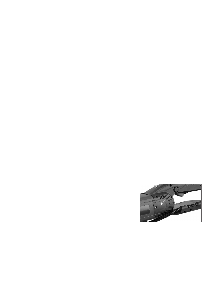
To replace
1. Remove the screw and remove the brush cover.
2. Using pliers rotate the brush spring out of the way and slide the
old carbon brush out of the brush holder.
3. Unscrew the screw to remove the brush lead. The old carbon
brush may now be lifted away.
4. Install a new brush. Installation is the reverse of removal.
5. Replace the brush cover.
WARNING: If the replacement of the power supply cord is necessary, this has to be done by the
manufacturer or their agent in order to avoid a safety hazard.
WARNING: All repairs must be entrusted to an authorized service center. Incorrectly performed repairs
could lead to injury or death.
Do not throw electric power tools into the household waste!
In accordance with the European Directive 2002/96/EG on Waste Electrical and Electronic Equipment and
transposition into national law, used electric power tools must be collected separately and recycled in an
environmentally friendly manner.
13
Brush Cover

EXPLODED VIEW
02
24
02
01
01
01
83
80
82
81
77
76
77
01
10
09
03
11
05
04
06
84
78
79
72
73
67
71
08
12
13
07
22
07
55
40
56
68
70
15
14
16
18
19-1
19-2
20
51
52
89
69
25
07
23
24
24
25
17
21
37
34
35
36
46
47
50
26
07
87
07
22
29
43
38
44
39
45
48
41
49
53
54
60
61
87
86
27
40
30
31
32
33
42
87
85
28
NO.01~90 Version 1.8
57
59
62
63
64
65
66
52
90-1
74
75
88
90-2
90-3
14

PARTS LIST
NO. Parts Name Q'TY
1 POWER SUPPLY CABLE (UL-12AWGx3Cx3M-SJT W) 1
1 POWER SUPPLY CABLE (UK-2.5x3Cx3M-H07RNF) 1
1 POWER SUPPLY CABLE (VDE-1.5x3Cx3M-H07RNF) 1
1 POWER SUPPLY CABLE (NO PLUG-1.5x3Cx2.7M-H07RNF) 1
2 PRCD INTERRUPTER PROTECTION (220V) 1
3 CORD ARMOR (Ø10.3/220V)/(Ø15.5110V) 1
4 CABLE CLIP 1
5 PANHEAD TAPPING SCREW (M4x14) 2
6 REED SWITCH 1
7 PANHEAD TAPPING SCREW (M4x12) 6
8 SWITCH ACTUATOR (LOCK-OFF) 1
9 SPRING (Ø0.8 x Ø6.4 x Ø8 x 9T x 26L) 1
10 PANHEAD TAPPING SCRE W-B (M4x16) 2
11 ELECTRONICS UNIT (110V/220V) 1
12 PANHEAD TAPPING SCRE W (M4x16) 4
13 BRUSH SPRING (0.4x4x3T) 2
14 CARBON BRUSH HOLDER (7x17) 2
15 INSULATION PLATE (10x38x1) 2
16 CARBON BRUSH (7x17x19) 2
16 CARBON BRUSH (7x17x19)(220V) 2
17 PANHEAD MACHINE SCREW (M4x6xP0.7) 2
18 MOTOR HOUSING 1
19 LED INDICATOR LIGHT 1
20 HANDLE HALF-RIGHT 1
21 HANDLE HALF-LEFT 1
22 CARBON CAP 2
23 HOSE RETAINER 1
24 PANHEAD TAPPING SCRE W (M4x20) 3
25 PANHEAD TAPPING SCRE W (M4x25) 3
26 PANHEAD TAPPING SCRE W (M4x50) 6
27 STATOR (110V/220V-100x54.1x75) 1
28 PANHEAD TAPPING SCRE W (M5x90) 2
29 BALL BEARING (6200) 1
30 FAN SHROUD 1
31 ARMATURE (110V/220V-100x54.1x75) 1
32 BALL BEARING (6202) 1
33 BEVEL PINION GEAR (M2.0 x 14T ) 1
34 TRUSS HEAD MACHINE SCREW (M4x6xP0.7) 1
35 EXTERNAL STAR WASHER (M4) 1
36 WIRE LEAD (1007-20#35CM) 1
37 CRIMP CAP CONNECTOR (C4)/C5 1
38 O-RING (Ø35x1.5) 1
39 GEAR HOUSING 1
40 SPRING WASHER (M5) 6
41 PANHEAD TAPPING SCRE W (M5x45) 2
42 PANHEAD TAPPING SCRE W (M5x50) 2
43 SPINDLE LOCK BUTTON 1
44 HEAD LOCKING KNOB (Ø7xØ12x5.6) 1
45 ARBOR LOCK 1
NO. Parts Name Q'TY
46 NEEDLE BEARING (TA1212) 1
47 BEVEL GEAR (M2.0x32T) 1
48 SOCKET CAP SCREW (M4x12xP0.7) 1
49 CLAMP PLATE 1
50 GEAR PLATE 1
51 BUMPER SPIKE 1
52 SOCKET CAP SCREW (M5x20xP0.8) 4
53 SOCKET SET SCREW (M6x8xP1.0) 1
54 SOCKET SET SCREW (M5x8xP0.8) 1
55 MOLDED GASKET (Ø2.5 x 30cm) 1
56 SOCKET CAP SCREW (M5x35xP0.8) 4
57 FIXING STUD 2
58 N/A -
59 RETAINING PLATE 1
60 SPLASH FLAP 1
61 NYLOCK NUT (M5xP0.8) 2
62 PARALLEL KEY (5x5x10) 2
63 SPINDLE 1
64 BALL BEARING (6004) 1
65 OIL SEAL (Ø20xØ32x5) 1
66 SPROCKET ARBOR 1
67 ADJUSTOR BLOCK 1
68 O-RING (Ø5x1) 1
69 TENSION ADJUSTOR SCREW 1
70 ADJUSTOR PLATE 1
71 FLAT HEAD MACHINE SCREW (M4x10xP0.7) 1
72 FLAT WASHER (Ø16xØ30x2) 1
73 EXTERNAL CIRCLIP (S-16) 1
74 SIDE COVER 1
75 FLANGE NUT (M8xP1.25) 2
76 HAND GUARD 1
77 TUBULAR SPIRIT LEVEL 2
78 SOCKET CAP SCREW (M5x25xP0.8) 2
79 WIRE HOSE CLAMP 1
80 WATER FEED CONNECTOR KIT 1
81 CABLE PROTECTOR (5/16"x110CM) 1
82 SPRING 1
83 WATER COUPLING 1
84 HOSE JOINER ( Ø9xØ12) 3
85 HOSE JOINER ( Ø12xØ12) 3
86 SIDE HANDLE 1
87 HANDLE BRACKET 1
88 SOCKET CAP SCREW (M8x16xP1.25) 3
89 BEVEL LOCK LEVER (M13) 1
90 PIN (Ø4x15.8) 2
90-1 SPROCKET 1
90-2 GUIDE BAR 1
90-3 DIAMOND CHAIN 1
15

Temperature Sensor
WIRING
SWITCH
LED
BRUSH
CARBON
BLOCK
CONNECTOR
Brown
Blue
WIRE
AC
WHITE
WHITE
BLACK
BLACK
BLACK
BLACK
MOTOR
CARBON
BRUSH
16
 Loading...