

Page 1
SC-19E, SC-22E, SC-24E & SC-27E LED-Backlit Display
displays.agneovo.com
User Manual
Page 2

TABLE OF CONTENTS
SAFETY INFORMATION
Federal Communications Commission (FCC) Notice (U.S. Only) ................................................................ 1
WEEE ........................................................................................................................................................... 2
PRECAUTIONS
Notice ...........................................................................................................................................................3
Cautions When Setting Up ........................................................................................................................... 3
Cautions When Using ...................................................................................................................................4
Cleaning and Maintenance ...........................................................................................................................4
Notice for the LCD Display ........................................................................................................................... 5
CHAPTER 1: PRODUCT DESCRIPTION
1.1 Package Contents .................................................................................................................................. 6
1.2 Installation ..............................................................................................................................................7
1.2.1 Installing the Stand ...................................................................................................................... 7
1.2.2 Adjusting the Viewing Angle ........................................................................................................ 8
1.2.3 Wall Mounting ..............................................................................................................................8
1.3 Control Buttons .....................................................................................................................................10
1.4 Overview .............................................................................................................................................. 11
1.4.1 Front View ................................................................................................................................. 11
1.4.2 Rear View .................................................................................................................................. 12
CHAPTER 2: MAKING CONNECTIONS
2.1 Connecting the AC Power .................................................................................................................... 13
2.2 Connecting Input Source Signals ......................................................................................................... 14
2.2.1 Connecting an Audio Device .....................................................................................................15
2.3 Connecting a Video Device .................................................................................................................. 16
2.4 Connecting a USB Storage Device (for rmware upgrade) ..................................................................16
2.5 Connecting an External Audio Device .................................................................................................. 17
CHAPTER 3: USING THE LCD DISPLAY
3.1 Turning on the Power ........................................................................................................................... 18
3.2 Using FREEZE Function ......................................................................................................................18
3.3 Adjusting the Volume ............................................................................................................................ 19
3.4 Muting Audio ......................................................................................................................................... 20
3.5 Locking the Control Buttons .................................................................................................................20
CHAPTER 4: ON SCREEN DISPLAY MENU
4.1 Using the OSD Menu ...........................................................................................................................22
4.2 OSD Menu Tree ................................................................................................................................... 23
CHAPTER 5: ADJUSTING THE LCD DISPLAY
5.1 Image Setting .......................................................................................................................................26
5.2 Audio Setting ........................................................................................................................................ 30
5.3 System .................................................................................................................................................31
5.4 Input Select ..........................................................................................................................................33
Page 3

TABLE OF CONTENTS
CHAPTER 6: APPENDIX
6.1 Warning Messages ...............................................................................................................................34
6.2 Troubleshooting ....................................................................................................................................35
6.3 Transporting the LCD Display .............................................................................................................. 36
CHAPTER 7: SPECIFICATIONS
7.1 Display Specications ..........................................................................................................................38
7.2 Display Dimensions .............................................................................................................................. 39
Page 4
SAFETY INFORMATION
Federal Communications Commission (FCC) Notice (U.S. Only)
This equipment has been tested and found to comply with the limits for a Class B digital
device, pursuant to part 15 of the FCC Rules. These limits are designed to provide reasonable
protection against harmful interference in a residential installation. This equipment generates,
uses and can radiate radio frequency energy and, if not installed and used in accordance with
the instructions, may cause harmful interference to radio communications. However, there
is no guarantee that interference will not occur in a particular installation. If this equipment
does cause harmful interference to radio or television reception, which can be determined
by turning the equipment off and on, the user is encouraged to try to correct the interference by
one or more of the following measures:
• Reorient or relocate the receiving antenna.
• Increase the separation between the equipment and receiver.
• Connect the equipment into an outlet on a circuit different from that to which the receiver is
connected.
• Consult the dealer or an experienced radio/TV technician for help.
Changes or modications not expressly approved by the party responsible for compliance could
void the user’s authority to operate the equipment.
Use only an RF shielded cable that was supplied with the display when connecting this display to a computer
device.
To prevent damage which may result in re or shock hazard, do not expose this appliance to rain or excessive
moisture.
THIS CLASS B DIGITAL APPARATUS MEETS ALL REQUIREMENTS OF THE CANADIAN INTERFERENCE-
CAUSING EQUIPMENT REGULATIONS.
This device complies with Part 15 of the FCC Rules. Operation is subject to the following two
conditions: (1) this device may not cause harmful interference, and (2) this device must accept
any interference received, including interference that may cause undesired operation.
1
Page 5

SAFETY INFORMATION
WEEE
Information for users applicable in European Union countries.
The symbol on the product or its packaging signies that this product has to be
disposed separately from ordinary household wastes at its end of life. Please
kindly be aware that this is your responsibility to dispose electronic equipment at
recycling centers so as to help conserve natural resources. Each country in the
European Union should have its collection centers for electrical and electronic
equipment recycling. For information about your recycling drop off area, please
contact your local related electrical and electronic equipment waste management
authority or the retailer where you bought the product.
2
Page 6
PRECAUTIONS
CAUTION
RISK OF ELECTRIC SHOCK
DO NOT OPEN
Symbols used in this manual
This icon indicates the existence of a potential hazard that could result in personal injury
or damage to the product.
This icon indicates important operating and servicing information.
Notice
• Read this User Manual carefully before using the LCD display and keep it for future reference.
• The product specications and other information provided in this User Manual are for reference only. All
information is subject to change without notice. Updated content can be downloaded from our web site at
displays.agneovo.com.
• To register online, go to displays.agneovo.com.
• To protect your rights as a consumer, do not remove any stickers from the LCD display. Doing so may
affect the determination of the warranty period.
Cautions When Setting Up
Do not place the LCD display near heat sources, such as a heater, exhaust vent, or in direct
sunlight.
Do not cover or block the ventilation holes in the housing.
Place the LCD display on a stable area. Do not place the LCD display where it may subject
to vibration or shock.
Place the LCD display in a well-ventilated area.
Do not place the LCD display outdoors.
Do not place the LCD display in a dusty or humid environment.
Do not spill liquid or insert sharp objects into the LCD display through the ventilation holes.
Doing so may cause accidental re, electric shock or damage the LCD display.
3
Page 7
PRECAUTIONS
Cautions When Using
Use only the power cord supplied with the LCD
display.
The power outlet should be installed near the LCD
display and be easily accessible.
If an extension cord is used with the LCD display,
ensure that the total current consumption plugged
into the power outlet does not exceed the ampere
rating.
Do not allow anything to rest on the power cord. Do
not place the LCD display where the power cord
may be stepped on.
If the LCD display will not be used for an indenite
period of time, unplug the power cord from the
power outlet.
To disconnect the power cord, grasp and pull by the
plug head. Do not tug on the cord; doing so may
cause re or electric shock.
Do not unplug or touch the power cord with wet
hands.
Warning:
Unplug the power cord
from the power outlet and
refer to qualied service
personnel under the following
conditions:
♦ When the power cord is
damaged.
♦ If the LCD display has been
dropped or the housing has
been damaged.
♦ If the LCD display emits smoke
or a distinct odor.
Cleaning and Maintenance
Use a soft cloth lightly moistened with a mild
detergent solution to clean the screen surface and
the housing.
Do not rub or tap the surface of the screen
with sharp or abrasive items such as a pen or
screwdriver. This may result in scratching the surface
of the screen.
Do not attempt to service the LCD display yourself,
refer to qualied service personnel. Opening or
removing the covers may expose you to dangerous
voltage or other risks.
Warning:
Ceiling mount or mount
on any other horizontal
surface overhead are not
advisable.
Installation in contravention of
the instructions may result in
undesirable consequences,
particularly hurting people and
damaging property. Users who
have already mounted the
display on the ceiling or any
other horizontal surface overhead
are strongly advised to contact
AG Neovo for consultations and
solutions to help ensure a most
pleasurable and fullling display
experience.
4
Page 8

PRECAUTIONS
Notice for the LCD Display
In order to maintain the stable luminous performance, it is recommended to use low brightness setting.
Due to the lifespan of the lamp, it is normal that the brightness quality of the LCD display may decrease
with time.
When static images are displayed for long periods of time, the image may cause an imprint on the LCD
display. This is called image retention or burn-in.
To prevent image retention, do any of the following:
• Set the LCD display to turn off after a few minutes of being idle.
• Use a screen saver that has moving graphics or a blank white image.
• Execute the Anti-Burn-in
• Switch desktop backgrounds regularly.
• Adjust the LCD display to low brightness settings.
• Turn off the LCD display when the system is not in use.
Things to do when the LCD display shows image retention:
• Turn off the LCD display for extended periods of time. It can be several hours or several days.
• Use a screen saver and run it for extended periods of time.
• Use a black and white image and run it for extended periods of time.
When the LCD display is moved from one room to another or there is a sudden change from low to high
ambient temperature, dew condensation may form on or inside the screen surface. When this happens, do
not turn on the LCD display until the dew disappears.
Due to humid weather conditions, it is normal for mist to form inside the screen surface of the LCD display.
The mist will disappear after a few days or as soon as the weather stabilizes.
There are millions of micro transistors inside the LCD display. It is normal for a few transistors to be
damaged and to produce spots. This is acceptable and is not considered a failure.
TM
function of the LCD display. Refer to page 31.
5
Page 9
Chapter 1: Product Description
CHAPTER 1: PRODUCT DESCRIPTION
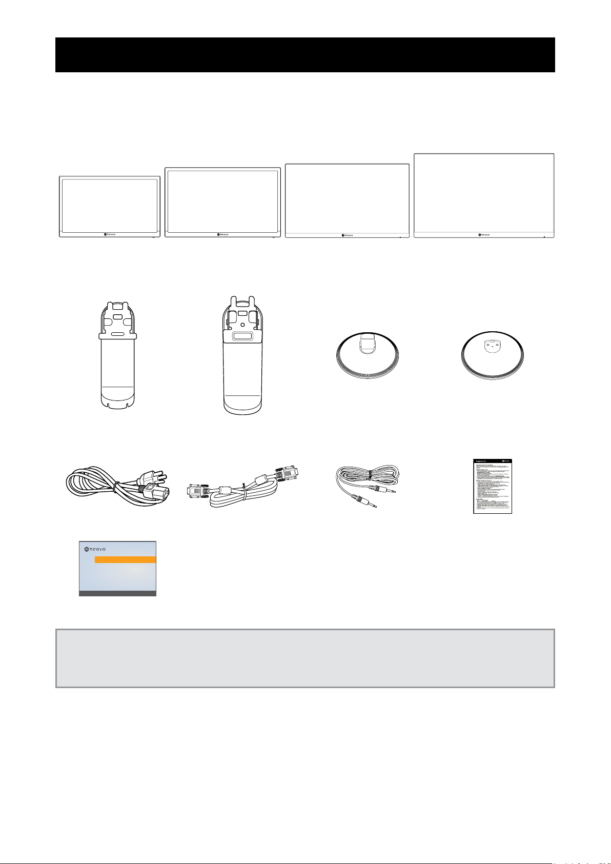
1.1 Package Contents
When unpacking, check if the following items are included in the package. If any of them is missing or
damaged, contact your dealer.
SC-19E SC-22E SC-24E SC-27E
LCD display
Stand for SC-
19E/22E/24E
Stand for SC-27E Base for SC-
19E/22E/24E
Base for SC-27E
Power Cord D-Sub Cable Audio Cable Warranty Card
SC-19E, SC-22E, SC-24E & SC-27E
Quick Start Guide
SC-19E, SC-22E, SC-24E & SC-27E LED-Backlit Display
www.agneovo.com
SC-19E/SC-22E/SC-24E/SC-27E_Quick Guide_V010
Quick Start Guide
Note:
• Use only the supplied power cord.
• The above pictures are for reference only. Actual items may vary upon shipment.
6
Page 10
PRODUCT DESCRIPTION
1.2 Installation
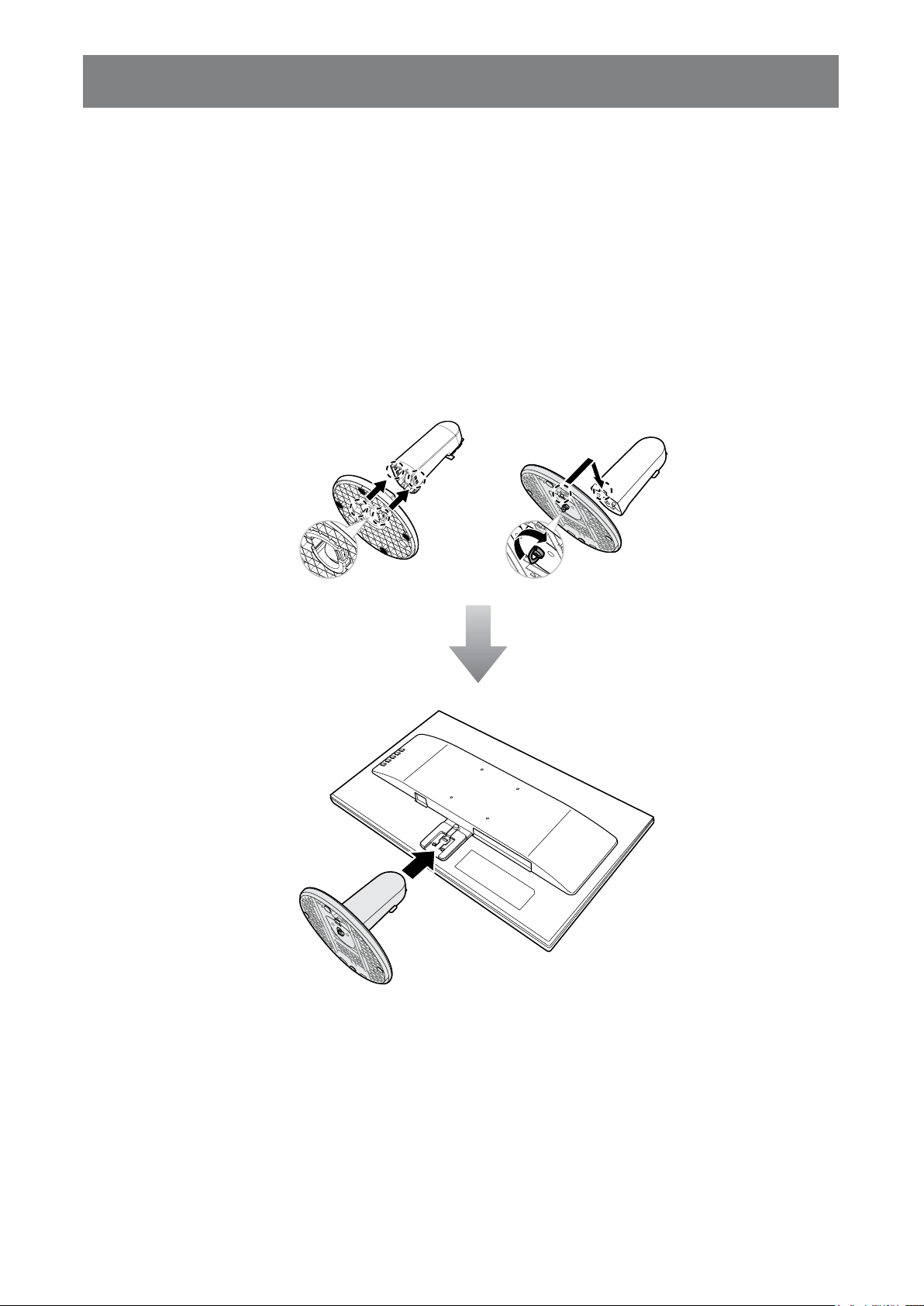
1.2.1 Installing the Stand
1. Place the LCD display with the screen side down on a cushioned surface.
2. Attach the base to the stand.
-SC-19E/22E/24E models: Press rmly on the base to secure the latches on the base into the slots on
the stand.
-SC-27E model: Attach the base to the stand and x with the screw to join them tightly.
3. Attach the stand to the display.
SC-19E/22E/24E SC-27E
7
Page 11
PRODUCT DESCRIPTION
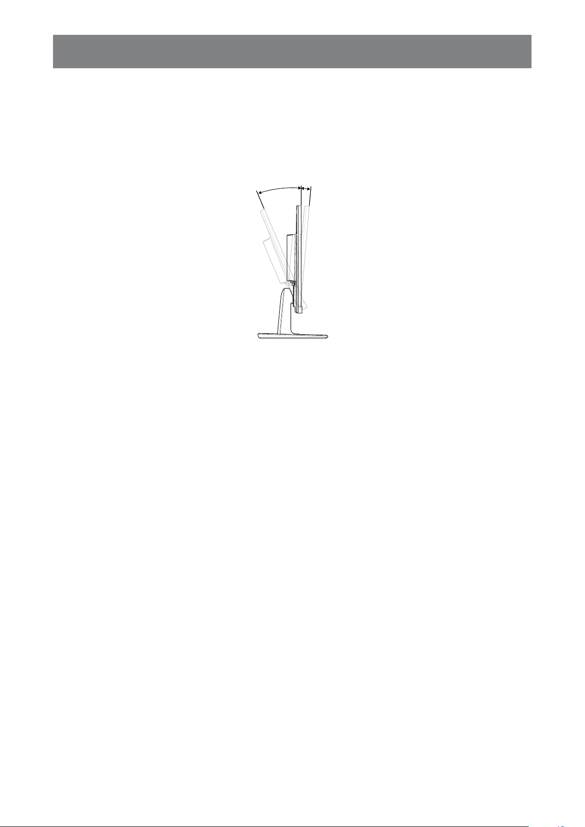
23°~-5°
1.2.2 Adjusting the Viewing Angle
For optimal viewing, it is recommended to look at the full face of the screen, then adjust the screen of the LCD display
angle according to your preference.
Hold the stand so that the screen does not topple when you make the adjustment.
You are able to adjust the screen angle as illustrated below:
1.2.3 Wall Mounting
To wall mount the LCD display, do the following steps:
1. Remove the stand.
Please refer to page 36.
8
Page 12
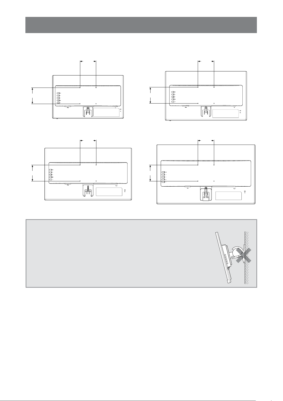
PRODUCT DESCRIPTION
100
mm
100
mm
2. Wall mount the LCD display.
Screw the mounting bracket to the VESA holes at the rear of the LCD display.
100
mm
CVBSINCVBS
HDMID-SUB
SC-19E SC-22E
100
mm
AUDIOINAUDIO
OUT
OUT
100
mm
100
mm
HDMI D-SUB
CVBSINCVBS
AUDIOINAUDIO
OUT
OUT
100
100
mm
HDMI D-SUBCVBSINCVBS
AUDIOINAUDIO
OUT
OUT
mm
HDMI D-SUBCVBSINCVBS
AUDIOINAUDIO
OUT
OUT
SC-24E SC-27E
Note: Take measures to prevent the LCD display from falling down and lessen possible injury and damage
to the display in case of earthquakes or other disasters.
• Use only the 100 x 100 mm wall mount kit recommended by AG Neovo. All
AG Neovo wall mount kits comply with VESA standard.
• Secure the LCD display on a solid wall strong enough to bear its weight.
• It is suggested to wall mount the LCD display without tilting it facing
downward.
9
Page 13
PRODUCT DESCRIPTION
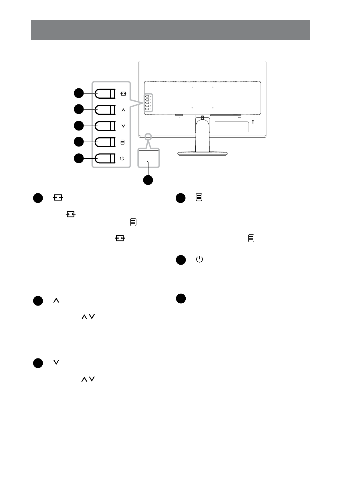
1.3 Control Buttons
1
2
3
4
5
]
[
1
Source/Exit
• Call out the Source quick menu. Press
the
button repeatedly to switch the
input source. Then press the button to
conrm.
• Press and the hold the
button to
freeze/unfreeze the screen. Refer to page
18.
• During OSD menu, close the OSD menu
or exit a submenu.
• During volume adjustment, close the quick
menu.
HDMI D-SUBCVBSINCVBS
AUDIOINAUDIO
OUT
OUT
6
[
4
] Menu/Enter
• Call out the OSD menu when OSD menu
is off.
• During OSD menu, conrm the selection
or enter a submenu.
• Press and hold the
button to mute/
unmute audio. Refer to page 20.
[
5
] Power
Turn the LCD display on. Press it again
to turn the LCD display off. Refer to page
18.
]
[
2
Up
• Call out the Volume quick menu. Then
press the
/ button to adjust the
volume level. Refer to page 19.
• During OSD menu, scroll through the
menu options, select an option, and adjust
the settings.
]
[
3
Down
• Call out the Volume quick menu. Then
press the
/ button to adjust the
volume level. Refer to page 19.
• During OSD menu, scroll through the
menu options, select an option, and adjust
the settings.
Power indicator
6
Indicate the operating status of the LCD
display:
- Lights blue when the LCD display is
turned on.
- Lights amber when the LCD display is in
standby mode.
- Lights off when the LCD display is turned
off.
10
Page 14

PRODUCT DESCRIPTION
1.4 Overview
1.4.1 Front View
1
2
SC-19E SC-22E
1
2
SC-24E SC-27E
1
2
1
2
1
Display screen
2
Control buttons
Press the button to perform its function. For more information about each button, refer to page 10.
11
Page 15

PRODUCT DESCRIPTION
1.4.2 Rear View
CVBSINCVBS
AUDIOINAUDIO
HDMID-SUB
OUT
OUT
9 9
SC-19E SC-22E
HDMI D-SUBCVBSINCVBS
AUDIOINAUDIO
OUT
OUT
CVBSINCVBS
HDMI D-SUB
HDMI D-SUBCVBSINCVBS
AUDIOINAUDIO
OUT
OUT
AUDIOINAUDIO
OUT
OUT
SC-24E SC-27E
HDMI D-SUB CVBSINCVBS
1 2 3 54 6 7 8
1
AC Power input
Use to connect the power cord.
2
HDMI connector
Use to connect an HDMI cable for digital input
signal.
3
D-SUB (VGA) connector
Use to connect a D-SUB (VGA) cable for
analogue input signal.
9 9
AUDIOINAUDIO
OUT
6
AUDIO IN connector
OUT
Use to connect an audio cable for audio input.
7
AUDIO OUT connector
Use to connect an audio cable for audio
output signal to an external audio device.
8
USB connector
Use to connect a ash disk for rmware
upgrade.
4
CVBS IN connector
Use to connect a composite cable for CVBS
input signal from a video device.
5
CVBS OUT connector
Use to connect a composite cable for CVBS
output signal to a video device.
12
9
Kensington security slot
Used for security and theft prevention.
Page 16

Chapter 2: Making Connections
CHAPTER 2: MAKING CONNECTIONS
CAUTION:
Make sure that the LCD display is not connected to the power outlet before making any
connections. Connecting cables while the power is ON may cause possible electric shock or
personal injury.
2.1 Connecting the AC Power
1. Connect the power cord to the AC power input at the rear of the LCD display.
2. Connect the power cord plug to a power outlet or a power supply.
CAUTION:
When unplugging the power cord, hold the power cord by the plug head. Never pull by the
cord.
13
Page 17

MAKING CONNECTIONS
2.2 Connecting Input Source Signals
Input source signals can be connected with either of the following cables:
• VGA
HDMI D-SUB
HDMI D-SUB
Connect one end of a D-SUB (VGA) cable to the D-SUB
(VGA) connector of the LCD display and the other end to
the D-SUB (VGA) connector of the computer.
• HDMI
Connect one end of an HDMI cable to the HDMI connector
of the LCD display and the other end to the HDMI
connector of the computer.
Computer
14
Page 18

MAKING CONNECTIONS
2.2.1 Connecting an Audio Device
1. Connect one end of an audio cable to the AUDIO IN connector at the rear of the LCD
display.
2. Connect the other end of an audio cable to the AUDIO OUT connector of the computer.
AUDIO
IN
AUDIO
OUT
Computer
15
Page 19

MAKING CONNECTIONS
2.3 Connecting a Video Device
1. Connect one end of a composite cable to the CVBS IN connector at the rear of the LCD
display.
2. Connect the other end of a composite cable to the CVBS OUT connector of your device.
CVBS
IN
CVBS
OUT
CVBS
OUT
Video Player
2.4 Connecting a USB Storage Device (for rmware upgrade)
Connect a USB storage device to the USB port of the LCD display for rmware upgrade.
16
Page 20

MAKING CONNECTIONS
2.5 Connecting an External Audio Device
1. Connect one end of an audio cable to the AUDIO OUT connector at the rear of the LCD
display.
2. Connect the other end of an audio cable to the AUDIO IN connector of the external audio
device.
AUDIO
OUT
AUDIO
IN
Audio Device
17
Page 21

Chapter 3: Using the LCD Display
CHAPTER 3: USING THE LCD DISPLAY
3.1 Turning on the Power
1. Plug the power cord to a power outlet or power supply.
2. Press the
When the LCD display is turned on, press the button to turn off the LCD display.
Note: The LCD display still consumes power as long as the power cord is connected to the power outlet.
Disconnect the power cord to completely cut off power.
button to turn the LCD display on.
Power button
3.2 Using FREEZE Function
The FREEZE function allows you to freeze the screen image but still continues real-time playback until the
image is unfreeze.
Press and hold the
displayed on the screen.
.
button for 3 seconds to activate screen freeze, the screen freeze message is
Source button
SCREEN FREEZE : ON
18
Page 22

USING THE LCD DISPLAY
Press and hold the button for 3 seconds again to deactivate screen freeze the screen freeze message is
displayed on the screen.
SCREEN FREEZE : OFF
The screen image displays the elapsed real-time playback image when screen freeze is deactivated.
3.3 Adjusting the Volume
1. Press the or button to call out the Volume quick menu.
Up/Down buttons
51
2. Press the or button to adjust the volume.
Note: During volume or menu setting adjustment, press and hold the / button to change the values
continuously.
19
Page 23

USING THE LCD DISPLAY
3.4 Muting Audio
Press and hold the button for 3 seconds to mute audio, the audio mute message is displayed on the
screen.
Menu button
MUTE
.
Press and hold the button for 3 seconds again to unmute.
Note: You can also disable the mute function by pressing the and buttons simultaneously.
3.5 Locking the Control Buttons
There are two options to lock the control buttons: lock all the buttons or lock all but Power button.
• To lock all the control buttons, press and hold the
displayed on the screen.
SOURCE+UP buttons
+ buttons for 3 seconds, the key lock message is
Key Lock
ON
20
Page 24

USING THE LCD DISPLAY
To unlock the control buttons, press and hold the + buttons for 3 seconds again, the key unlock
message is displayed on the screen.
Key Lock
OFF
• To lock all the control buttons except for the Power button, press and hold the + buttons for 3
seconds, the key lock message is displayed on the screen.
DOWN+MENU buttons
Key Lock
ON
To unlock the control buttons, press and hold the + buttons for 3 seconds again, the key unlock
message is displayed on the screen.
Key Lock
OFF
21
Page 25

Chapter 4: On Screen Display Menu
CHAPTER 4: ON SCREEN DISPLAY MENU
4.1 Using the OSD Menu
1. Press the button to call out the OSD window.
Main menu
IMAGE SETTING
PICTURE MODE
CONTRAST
BRIGHTNESS
SATURATION
Menu options
2. Press the or button to select a menu and press the button to enter the selected
menu.
TINT
SHARPNESS
COLOUR TEMP.
ASPECT RATIO
PC SETTING
NOISE REDUCTION
GAMMA
CCTV
HIGH
2.0
85
48
48
50
60
Submenu
IMAGE SETTING
PICTURE MODE
CONTRAST
BRIGHTNESS
SATURATION
TINT
SHARPNESS
COLOUR TEMP.
ASPECT RATIO
PC SETTING
NOISE REDUCTION
GAMMA
CCTV
HIGH
2.0
PICTURE MODE
85
48
48
50
60
CONTRAST
BRIGHTNESS
SATURATION
TINT
SHARPNESS
COLOUR TEMP.
ASPECT RATIO
PC SETTING
NOISE REDUCTION
GAMMA
IMAGE SETTING
CCTV
85
48
48
50
60
HIGH
2.0
The selected menu option is highlighted in gray.
3. Press the or button to select an option and press the button to enter its submenu.
IMAGE SETTING
PICTURE MODE
CONTRAST
BRIGHTNESS
SATURATION
TINT
SHARPNESS
COLOUR TEMP.
ASPECT RATIO
PC SETTING
NOISE REDUCTION
GAMMA
CCTV
HIGH
2.0
PICTURE MODE
85
48
48
50
60
CONTRAST
BRIGHTNESS
SATURATION
TINT
SHARPNESS
COLOUR TEMP.
ASPECT RATIO
PC SETTING
NOISE REDUCTION
GAMMA
IMAGE SETTING
CCTV
85
48
48
50
60
HIGH
2.0
The menu option then appears between the two arrows (
).
4. Press the or button to adjust the settings.
5. To exit the submenu, press the
6. To close the OSD window, press the
button.
button repeatedly.
Note: When settings are modied, all changes are saved when the user does the following:
• Proceeds to another menu
• Exits the OSD menu
• Waits for the OSD menu to disappear
22
Page 26

ON SCREEN DISPLAY MENU
4.2 OSD Menu Tree
Main Menu Submenu Reference
Picture Mode Standard Refer to pages 26-29.
Image Settings (
)
CCTV
Video
Contrast
Brightness
Saturation
Tint
Sharpness
Colour Temp. Cool
Neutral
Warm
User
Aspect Ratio (Full, Native, Real,
Zoom)
PC Setting Auto adjust
Noise Reduction Off
Gamma 1.8
H. Zoom
V. Zoom
Overscan
H. Position
V. Position
Phase
Clock
Low
Mid
High
2.0
2.2
2.4
S
Backlight
Black Level
DCR On
Off
23
Page 27

ON SCREEN DISPLAY MENU
Main Menu Submenu Reference
Color Range Auto Refer to pages 26-29.
Image Settings (
Audio Setting (
)
Full
Limit
Volume Refer to page 30.
)
Mute On
Off
Source PC
Video
System (
)
Language English Refer to pages 31-33.
Français
Deutsch
Italiano
Español
Nederlands
Română
Česky
Polski
Русский
简中
繁中
Recall
F/W Update
Information Input Select:
Resolution:
Horizontal Freq.:
Vertical Freq.:
Timing Mode:
F/W Version:
Anti-Burn-In Enable (On/Off)
Interval (hours)
(4, 5, 6, 8)
Mode (A, B, C)
Alink On
Off
24
Page 28

ON SCREEN DISPLAY MENU
Main Menu Submenu Reference
System (
)
Power Saving On Refer to pages 31-33.
Off
Source Detect Auto
Manual
Blue Screen On
Off
Signal Info On
Off
Logo On
Off
LED On
Off
Low Power On
Off
OSD Transparency
OSD Timer
Input Select (
Note: Availability of some menu items depend on the input source signal and current setting. If the menu is
not available, it is disabled and grayed out.
)
VGA Refer to page 33.
HDMI
CVBS
25
Page 29

Chapter 5: Adjusting the LCD Display
CHAPTER 5: ADJUSTING THE LCD DISPLAY
5.1 Image Setting
1. Press the button to call out the OSD window.
2. Press the
or button to select and press the button to enter the Image Setting
menu.
IMAGE SETTING
PICTURE MODE
CONTRAST
BRIGHTNESS
SATURATION
TINT
SHARPNESS
COLOUR TEMP.
ASPECT RATIO
PC SETTING
NOISE REDUCTION
GAMMA
CCTV
HIGH
2.0
PICTURE MODE
85
48
48
50
60
CONTRAST
BRIGHTNESS
SATURATION
TINT
SHARPNESS
COLOUR TEMP.
ASPECT RATIO
PC SETTING
NOISE REDUCTION
GAMMA
IMAGE SETTING
CCTV
HIGH
2.0
3. Press the or button to select an option and press the button to enter its submenu.
Item Function Operation Range
Picture Mode Chooses a predened picture setting.
Note: Select the suggested colour space
to match the corresponding picture mode
Press the
or button
to select the setting.
Standard (RGB)
CCTV (YUV)
Video (YUV)
for optimal results.
Contrast Adjusts the difference between the black
level and the white level.
Press the
or button
to adjust the value.
0 to 100
85
48
48
50
60
Original Setting High Setting Low Setting
Brightness Adjusts the luminance of the screen
image.
Original Setting High Setting Low Setting
Saturation Adjusts the colour saturation of the screen
image.
Press the
or button
to adjust the value.
Press the
or button
to adjust the value.
0 to 100
0 to 100
Note: This menu option is only available if
the input source is CVBS or HDMI.
26
Page 30

ADJUSTING THE LCD DISPLAY
Item Function Operation Range
Tint Adjusts the colour tint.
Note: This menu option is only available if
the input source is CVBS or HDMI.
Sharpness Adjust the clarity and focus of the screen
image.
Note: This menu option is only available if
the input source is CVBS or HDMI.
Colour Temp.
(Colour
Provides several colour adjustment
settings.
Temperature)
If the Colour Temp. setting is set to User, you can customize the colour temperature by
adjusting the red, green, or blue setting according to your preference.
COLOUR TEMP.
R
G
B
Press the
to adjust the value.
Press the
to select the setting.
COLOUR TEMP.
USER
or button
or button
92
101
128
0 to 100
Cool
Neutral
Warm
User
a. Select User and press the button.
b. Press the
or button to select the colour you want to adjust. Then press the
button to enter its submenu.
c. Press the
or button to adjust the value (0~255).
27
Page 31

ADJUSTING THE LCD DISPLAY
Item Function Operation Range
Aspect Ratio Adjusts the aspect ratio of the screen
image.
• If the Aspect Ratio setting is set to Zoom, you can customize the aspect ratio by
adjusting the horizontal zoom (H. Zoom) and/or vertical zoom (V. Zoom) according to
your preference.
ASPECT RATIO
H. ZOOM
V. ZOOM
OVERSCAN
a. Select Zoom and press the button.
b. Press the
or button to select the zoom parameter that you want to adjust.
Then press the button to enter its submenu.
Press the
to select the setting.
ASPECT RATIO
ZOOM
or button
0
0
0
Full
Native
Real
Zoom
PC Setting
Note: This
menu option is
only available if
the input source
is VGA.
c. Press the
or button to adjust the value (0 ~ 100).
• If the Aspect Ratio setting is set to Full, Native, or Zoom, you can x the cut-off
screen edges by adjusting the Overscan parameter.
a. Select Full, Native, or Zoom and press the
b. Press the
or button to select Overscan. Then press the button to enter
button.
its submenu.
c. Press the
or button to adjust the value (0 ~ 100).
Auto Adjust: Automatically optimizes the display of VGA input image.
H. Position (Horizontal Position): Moves
the OSD window to the left or right of the
Press the
or button
to adjust the value.
0 to 100
screen.
V. Position (Vertical Position): Moves the
OSD window up or down the screen.
Clock: Adjusts the frequency timing to
synchronize with the video signal.
Phase: Adjusts the phase timing to
synchronize with the video signal.
28
Page 32

ADJUSTING THE LCD DISPLAY
Item Function Operation Range
Noise
Reduction
Gamma Adjusts the non-linear setting for picture
Adjusts the noise reduction to help remove
noise from images. This helps produce
clearer and crisper images.
Note: This menu option is only available if
the input source is CVBS or HDMI.
Noise Reduction Off
luminance and contrast.
Press the
to select the setting.
Press the
to select the setting.
or button
Noise Reduction On
or button
Off
Low
Mid
High
1.8
2.0
2.2
2.4
S
Backlight Adjusts the luminance of the screen
image.
Black Level Adjusts the black level of the screen
image. Low brightness setting makes black
colour darker.
DCR (Dynamic
Contrast Ratio)
Color Range Adjusts black and white levels for video.
Activates DCR. This feature provides
automatic adjustment of dynamic
luminance (Backlight) range, such as
when watching movies. DCR is suitable for
indoor viewing.
Note: This menu option is only available if
the input source is HDMI.
Press the
to adjust the value.
Press the
to select the setting.
or button
or button
0 to 100
On
Off
Auto
Full
Limit
29
Page 33

ADJUSTING THE LCD DISPLAY
5.2 Audio Setting
1. Press the button to call out the Audio Setting menu.
2. Press the
or button to select and press the button to enter the Audio Setting
menu.
VOLUME
MUTE
SOURCE
AUDIO SETTING
OFF
VIDEO
50
VOLUME
MUTE
SOURCE
AUDIO SETTING
OFF
VIDEO
3. Press the or button to select an option and press the button to enter its submenu.
Item Function Operation Range
Volume Adjusts the volume level of the built-in
speaker.
Mute Turns the audio speaker on or off. While off,
a screen message is displayed as follows:
Press the
or button
to adjust the value.
Press the
or button
to select the setting.
0 to 100
On
Off
50
MUTE
Note: You can also mute/unmute audio by
pressing and holding the button for 3
seconds. Refer to page 20.
Source Selects the audio source for the PC or Video
input signal.
Note: This menu option is only available if
the input source is HDMI.
PC
Video
30
Page 34

ADJUSTING THE LCD DISPLAY
5.3 System
1. Press the button to call out the OSD window.
2. Press the
or button to select and press the button to enter the System menu.
LANGUAGE
RECALL
F/W UPDATE
INFORMATION
ANTI-BURN-IN
Alink
POWER SAVING
SOURCE DETECT
BLUE SCREEN
SIGNAL INFO
LOGO
SYSTEM
English
OFF
ON
MANUAL
OFF
ON
ON
LANGUAGE
RECALL
F/W UPDATE
INFORMATION
ANTI-BURN-IN
Alink
POWER SAVING
SOURCE DETECT
BLUE SCREEN
SIGNAL INFO
LOGO
SYSTEM
English
OFF
ON
MANUAL
OFF
ON
ON
3. Press the or button to select an option and press the button to enter its submenu.
Item Function Operation Range
Language Select the OSD language.
Press the
or button
to select the setting.
English
Français
Deutsch
Italiano
Español
Nederlands
Română
Česky
Polski
Русский
简中
繁中
Recall Use to recall all to default settings, except
Language. Select Yes when you are
prompted to conrm resetting all the setting.
Press the
button to
reset all the setting to the
factory defaults.
Yes
No
F/W Update Connect a USB storage device to the USB port of the LCD display for rmware upgrade.
For more information on connecting a USB device, please refer to page 16.
Information Displays settings information such as Input Select, Resolution, Horizontal and Vertical
Frequency, Timing mode, and Firmware version.
Note: Information on horizontal frequency, vertical frequency, and time mode is only
available if the input source is VGA.
Anti-Burn-In Enable: Enables or disables Anti-Burn-in
function.
Interval (Hours): Sets the interval time
(hour) between activating the Anti-Burn-in
function.
TM
Press the
to select the setting.
TM
or button
On
Off
4
5
6
8
31
Page 35

ADJUSTING THE LCD DISPLAY
Item Function Operation Range
Anti-Burn-In Mode: Selects the “Anti-Burn-In” mode:
• A - Executes fast.
• B - Slower but more precise than mode
A.
• C - Slowest but the most precise
TM
Anti-Burn-in
Alink Synchronizes powering on/off via HDMI.
Note: This menu option is only available if
the input source is HDMI.
Power Saving Enables or disables power saving mode.
When the LCD display turns into power
saving mode, the screen turns black and the
LED indicator lights amber.
Note: The amount of time for the display to
enter power saving varies depending on the
Source Detect setting. If the Source Detect
is set to Auto, the display checks all input
source signals before entering power saving
mode if no signal is detected; this takes up
more time. If the Source Detect is set to
Manual, the display enters power saving
mode right away.
mode.
Press the
to select the setting.
or button
A
B
C
On
Off
Source Detect Sets the display to automatically or manually
detect the input source signal.
Blue Screen Enables or disables the blue screen feature.
If the setting is set to On, it displays a blue
screen when no signal is available.
Signal Info Enables or disables the signal information to
be displayed on the screen.
Logo Enables or disables the logo feature. If the
setting is set to On, the AG Neovo logo is
briey displayed after the display is powered
on.
LED Turns the LED indicator on or off while using
the LCD monitor.
Low Power * To unlock backlight before any customisation
settings.
* Product features may vary by models
Auto
Manual
On
Off
32
Page 36

ADJUSTING THE LCD DISPLAY
Item Function Operation Range
OSD
Sets the transparency of the OSD menu.
Transparency
OSD Timer Sets the length of time (in seconds) the OSD
screen is displayed. When the time elapses,
the OSD screen is automatically inactivated
5.4 Input Select
1. Press the button to call out the OSD window.
2. Press the
or button to select and press the button to enter the Input Select menu.
INPUT SELECT
VGA
HDMI
CVBS
Press the
or button
to adjust the value.
INPUT SELECT
VGA
HDMI
CVBS
0 to 100
3. Press the or button to select an input source and press the button to set the input
source.
Item Function
VGA Sets VGA as the input source signal.
HDMI Sets HDMI as the input source signal.
CVBS Sets CVBS as the input source signal.
33
Page 37

Chapter 6: Appendix
CHAPTER 6: APPENDIX
6.1 Warning Messages
When any of these warning messages appear, check the following items.
Warning Message Cause Solution
Unsupported
NO SIGNAL
Key Lock
ON
ANTI-BURN-IN
ON
The resolution or the refresh
rate of the graphics card of
the computer is set too high.
The LCD display cannot
detect the input source
signal.
The OSD has been locked
by the user.
The Anti-Burn-inTM function
has been enabled by the
user.
√ Change the resolution or the
refresh rate of the graphics
card.
√ Check if the input source is
turned ON.
√ Check if the signal cable is
properly connected.
√ Check if any pin inside the
cable connector is twisted or
broken.
√ Press and hold the
buttons for 3 seconds to unlock
the control buttons.
√ Set the “Anti-Burn-In” >
Enable setting to Off in System
( ) menu (refer to page
31).
+
SCREEN FREEZE : ON
MUTE
The FREEZE has been
activated.
The Mute function is
enabled.
√ Press and the hold the
button to unfreeze the screen.
√ Press and hold the
3 seconds to disable the mute
function.
√ Press the
simultaneously to disable the
mute function.
and buttons
button for
34
Page 38

APPENDIX
6.2 Troubleshooting
Problems Possible Cause and Solution
No picture.
• LED indicator is OFF.
• LED indicator is amber. • Check if the computer is turned ON.
Image position is incorrect. • For VGA input, adjust the H. Position and V. Position settings in
The displayed texts are
blurry.
Red, blue, green, white
dots appear on the screen.
No audio output. • Check if the volume is set to 0 or the Mute function is enabled (refer to
• Check if the LCD display is turned ON.
• Check if the power cord is plugged into the power outlet.
• Check if the computer is in standby mode, move the mouse or press
any key to wake up the computer.
Image Setting (
• For VGA input, do the following:
√ Auto-adjust the display (refer to page 28).
√ Adjust the Clock and Phase settings in Image Setting (
(refer to page 28).
• There are millions of micro transistors inside the LCD display. It is
normal for a few transistors to be damaged and to produce spots. This
is acceptable and is not considered a failure.
pages 19-20).
) menu (refer to page 28).
) menu
Dew formed on the LCD
display.
Faint shadows from a
static image appear on the
screen.
• For VGA input, check the audio setting of the computer.
• This normally happens when the LCD display is moved from a cold
room to a hot room temperature. Do not turn ON the LCD display, wait
for the dew condensation to disappear.
• Turn off the LCD display for extended periods of time.
• Use a screen saver or a black and white image and run it for extended
periods of time.
35
Page 39

APPENDIX
6.3 Transporting the LCD Display
To transport the LCD display for repair or shipment, place the display in its original packaging box.
Note:
• When repacking, carefully place the LCD display in its box and protect the screen surface from
touching any object.
1. Remove the stand.
a. Place the LCD display with the screen side down on a cushioned surface.
b. Press down on the release latch to unlock the stand and then slide the stand out of the recess on
the display.
Release latch
36
Page 40

APPENDIX
2. Detach the base from the stand.
-SC-19E/22E/24E models: Pinch the latches to unlock the base and then remove the base from the stand.
-SC-27E model: Unscrew the base and then remove the base from the stand.
SC-19E/22E/24E SC-27E
3. Put the LCD display inside its original plastic. Then place the LCD display with the screen
side down on the foam cushion.
4. Put all other contents on their designated area (if necessary).
5. Close and tape the box.
37
Page 41

Chapter 7: Specifications
CHAPTER 7: SPECIFICATIONS
7.1 Display Specications
SC-19E SC-22E SC-24E SC-27E
Panel Panel Type LED-Backlit TFT LCD
Panel Size 18.5 21.5 23.8 27.0
Max. Resolution 1366 x 768 FHD 1920 x 1080 FHD 1920 x 1080 FHD 1920 x 1080
Pixel Pitch 0.300 mm 0.248 mm 0.275 mm 0.311mm
Brightness 250 cd/m² 250 cd/m² 250 cd/m² 300 cd/m²
Contrast Ratio 20,000,000:1 (DCR) 20,000,000:1 (DCR) 20,000,000:1 (DCR) 20,000,000:1 (DCR)
Viewing Angle (H/V) 170°/160° 170°/160° 178°/178° 178°/178°
Display Colour 16.7M 16.7M 16.7M 16.7M
Response Time 3 ms 3 ms 5 ms 5 ms
Horizontal Resolution TV Lines 600TVL (NTSC), 625TVL (PAL) 600TVL (NTSC), 625TVL (PAL) 600TVL (NTSC), 625TVL (PAL) 600TVL (NTSC), 625TVL (PAL)
Frequency (H/V) H Freq. 24 kHz-83 kHz 24 kHz-83 kHz 24 kHz-83 kHz 24 kHz-83 kHz
V Freq. 50 Hz-75 Hz 50 Hz-75 Hz 50 Hz-75 Hz 50 Hz-75 Hz
Input HDMI 1.4 x 1 1.4 x 1 1.4 x 1 1.4 x 1
VGA 15-Pin D-Sub x 1 15-Pin D-Sub x 1 15-Pin D-Sub x 1 15-Pin D-Sub x 1
Composite BNC x 1 BNC x 1 BNC x 1 BNC x 1
Output Composite BNC x 1 BNC x 1 BNC x 1 BNC x 1
Audio Audio In Stereo Audio Jack (3.5 mm) Stereo Audio Jack (3.5 mm) Stereo Audio Jack (3.5 mm) Stereo Audio Jack (3.5 mm)
Audio Out Stereo Audio Jack (3.5 mm) Stereo Audio Jack (3.5 mm) Stereo Audio Jack (3.5 mm) Stereo Audio Jack (3.5 mm)
Internal Speakers 2W x 2 2W x 2 2W x 2 2W x 2
Power Power Supply Internal Internal Internal Internal
Power Requirements AC 100-240V, 50/60 Hz AC 100-240V, 50/60 Hz AC 100-240V, 50/60 Hz AC 100-240V, 50/60 Hz
On Mode
Stand-by Mode < 0.5W < 0.5W < 0.5W < 0.5W
Off Mode < 0.5W < 0.5W < 0.5W < 0.5W
Operating Conditions Temperature 0°C-40°C (32°F-104°F) 0°C-40°C (32°F-104°F) 0°C-40°C (32°F-104°F) 0°C-40°C (32°F-104°F)
Humidity
Storage Conditions Temperature -20°C-55°C (-4°F-131°F) -20°C-55°C (-4°F-131°F) -20°C-55°C (-4°F-131°F) -20°C-60°C (-4°F-140°F)
Humidity 5%-93% (non-condensing) 5%-93% (non-condensing) 5%-93% (non-condensing) 5%-90% (non-condensing)
Mounting VESA FPMPMI Yes (100 x 100 mm) Yes (100 x 100 mm) Yes (100 x 100 mm) Yes (100 x 100 mm)
Stand Tilt -5° to 23° -5° to 23° -5° to 23° -5° to 23°
Security Kensington Security
Dimensions Product with Base
Weight Product with Base 2.3 kg (5.1 lb) 2.8 kg (6.2 lb) 3.8 kg (8.2 lb) 5.3 kg (11.7 lb)
Slot
(W x H x D)
Packaging
(W x H x D)
Packaging 3.6 kg (7.9 lb) 4.2 kg (9.3 lb) 5.4 kg (11.9 lb) 7.3 kg (16.1 lb)
(TN Technology)
16W (On) 21W (On) 22W (On) 23W (On)
10%-80% (non-condensing) 10%-80% (non-condensing) 10%-80% (non-condensing) 10%-90% (non-condensing)
Yes Yes Yes Yes
441.9 x 356.2 x 194.0 mm
(17.4" x 14.0" x 7.6")
492.0 x 360.0 x 123.0 mm
(19.4" x 14.2" x 4.8")
LED-Backlit TFT LCD
(TN Technology)
505.2 x 380.8 x 194.0 mm
(19.9" x 15.0" x 7.6")
557.0 x 387.0 x 117.0 mm
(21.9" x 15.2" x 4.6")
LED-Backlit TFT LCD
(IPS Technology)
540.6 x 396.1x 194.0 mm
(21.3" x 15.6" x 7.6")
620.0 x 420.0 x 122.0 mm
(24.4" x 16.5" x 4.8")
LED-Backlit TFT LCD
(VA Technology)
611.9 x454.7 x238.7 mm
(24.1" x 17.9" x 9.4")
704.0 x 460.0 x 140.0 mm
(27.7" x 18.11" x 5.5")
Note: All specications are subject to change without prior notice.
38
Page 42

SPECIFICATIONS
14.25
100
99
106
7.2 Display Dimensions
SC-19E
~-5°
23°
15.3
16.3
268.3(outline dimension)
232.0(opening dimension)
20
220.95
441.9(outline dimension)
411.3(opening dimension)
220.95
48.3
19.9
15.3
132.4
356.2
135.9
1.6
86.4
194.0
14.25
170.95
100
170.95
M4x10L
60.5
134.8
73
413.4
76.8
100
91.5
SC-22E
Ø194.0
48.3
22.1
505.2(outline dimension)
~-5°
23°
13.8
15.3
305.0(outline dimension)
269.4(opening dimension)
20.3
477.8(opening dimension)
252.6
252.6
13.8
150
155
1.6
380.8
74.3
194
202.6
83.3
134.6
87.1
23
100
459.3
202.6
M4x10L
AUDIO
AUDIO
HDMI
D-SUB
IN
OUT
IN
OUT
23
Ø194
39
Page 43

SPECIFICATIONS
100
105
117.6
SC-24E
49.6
Detail A Detail A
19.7
2:1
46.9(top bezel & rear cover)
(outline dimension)
540.6
~-5°
23°
2.8
(opening dimension)
535
2.8
2.8
49.6(bottom bezel & rear cover)
220.3
100
220.3
86
155
137.9
AUDIO
AUDIO
HDMI
D-SUB
IN
OUT
IN
OUT
23
322.6(outline dimension)
301.5(opening dimension)
18.3
270.3
270.3
167.6
396.1
73.5
194
98.6
23
494.6
Ø194.0
SC-27E
23°
~-5°
Detail A
2.8
2.8
(outline dimension)
(opening dimension)
341.3
366.6
22.5
305.9
(outline dimension)
611.9
(opening dimension)
606.3
305.9
Ø238.7
51.9
Detail A
2:1
23.4
49.0 (top bezel & rear cover)
51.9 (bottom bezel & rear cover)
2.8
256
100
94.2
175.2
167.9
454.7
191.4
104.5
256
M4x10L
125.2
100
AUDIO
AUDIO
HDMI
D-SUB
CVBS
CVBS
IN
OUT
IN
OUT
141.4
88.1
238.7
23
565.9
23
AG Neovo
Company Address: 5F-1, No. 3-1, Park Street, Nangang District, Taipei, 11503, Taiwan.
Copyright © 2019 AG Neovo. All Rights Reserved.
S27E00/S24E00/S22E00/S19E00_UM_V011
40
 Loading...