

Page 1
Page 2

Table of Contents
Precautions...............................................................................................................2
Warning on installation................................... ................................... ..............2
Warning on power connection.........................................................................2
Warning on tilt .................................................................................................3
Warning on Maintenance.................................................................................3
Warning on transportation...............................................................................3
Getting Started..........................................................................................................4
Package Contents.................................................. ............... ............... ...........4
Identify the Parts and Controls........................................................................5
Setup...............................................................................................................8
Customising Your Display .......................................................................................10
Adjusting Your LCD Panel.............................................................................10
Selecting OSD Features................................................................................10
OSD Menus...................................................................................................11
Warning Messages and Troubleshooting.......................................... ............... .......17
Warning Messages........................................................................................17
Troubleshooting.............................................................................................18
Technical Specifications..........................................................................................19
Specifications................................................................................................19
Regulation...............................................................................................................20
FCC compliance............................................................................................20
WEEE............................................................................................................20
Hg..................................................................................................................21
Medical Product ............................................................................................21
1
Page 3

Precautions
Warning on installation
Do not cover or block the ventilation holes in the case.
Do not install the display near heat sources such as radiators or air ducts, or in a place
subject to direct sunlight, excessive dust, mechanical vibration or shock.
Warning on power connection
Use an appropriate power cord for your local power supply.
The outlet should be installed near the display and be easily accessible.
Do not allow anything to r e st on the power cord.
Disconnect the power plug from the power outlet under following conditions:
If you will not use it for an indefinite period time.
When the power cord or plug is damaged of frayed.
If the product has been dropped or the cabinet has been damaged.
If the product exhibits a distinct change in performance, indicate a need for service.
Remark: Please be advised that IEC 60601-1 certification is only applicable when using DR-17
together with the 24V adapter that supplied by AG Neovo. If you use any adapter other than
24V adapter that was supplied with DR-17, then IEC 60601-1 certific ation will not be applic able.
2
Page 4
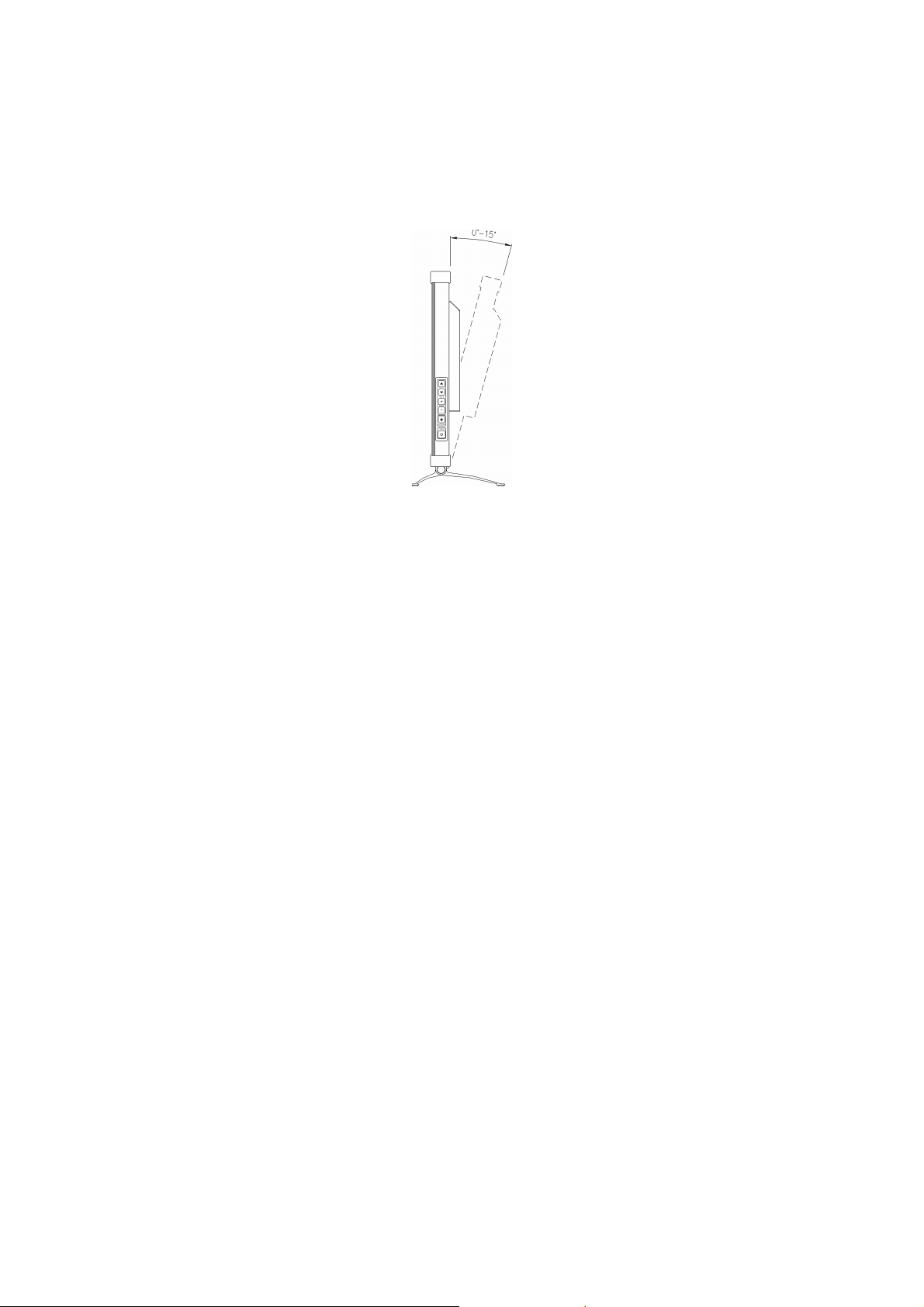
Warning on tilt
Use the display’s tilt capability to adjust its vertical orientation to an appropriate position. Grasp
the top corners of the display with both hands and tilt to the desired angle.
DR-17
Warning on Maintenance
Clean the cabinet, glass, and controls with a soft cloth lightly moistened with a mild
detergent solution. Do not use any type of abrasive pad, scouring powder or solvent, such
as alcohol or benzene.
Do not rub, touch, or tap the surface of the screen with sharp or abrasive items such as a
pen or screwdriver. This type of contact may result in a scratched glass.
Do not insert sharp objects or spill liquid into the display through ventilation holes. They
may cause accident fire, electric shock or failure.
Do not attempt to service this product yourself, as opening or removing covers may
expose you to dangerous voltage potentials or other risks.
Warning on transportation
When you transport this display for repair or s hipment, us e th e original carton and p acking
materials.
3
Page 5
Getting S tarte d
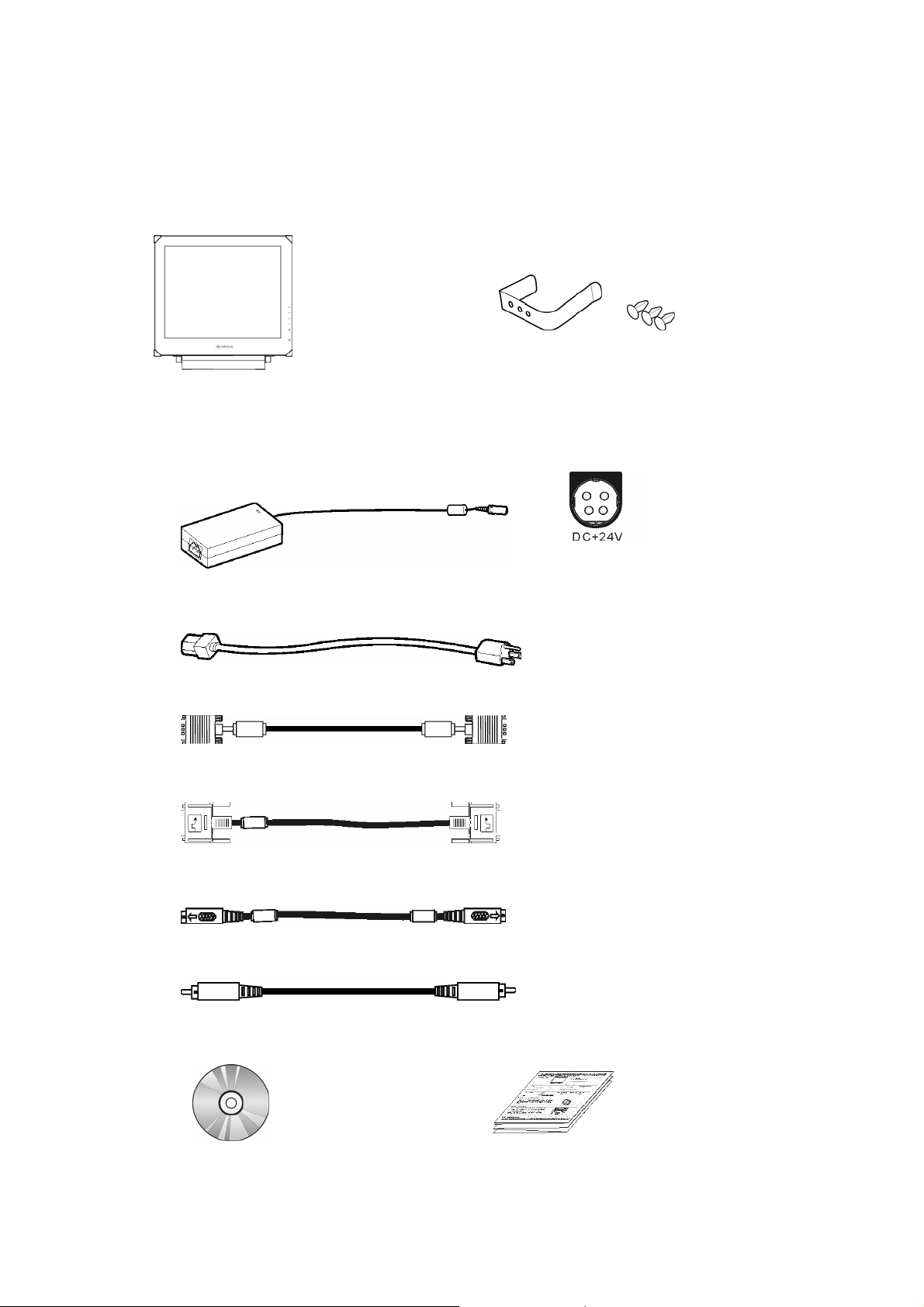
Package Contents
Before using this display, check the following items are included in your carton box:
Display (*1)
X-ray film positioner (*1) with its rivets (*3)
DC 24V Power adaptor (*1)
1. Please use the power adapter which provided by the manufacturer.
2. Must use one of the following adapters: Sinpro MPU63-108 or Adapter STD-2427M.
Power cord (*1) (Above 0.75mm * 3C)
D-sub 15-pin signal cable (*1)
Digital DVI signal cabl e ( *1)
S- Video cable (*1)
CVBS cable (*1)
CD-ROM (*1)
Quick Guide (*1)
4
Page 6
VGA
A
Identify the Parts and Controls
EQUIPOTENTIAL
TERMINAL
DIGITAL
INPUT
INPUT
Equipotential Terminal
Brings the various parts of a system to th e sa me potential.
Digital-In
DVI-D connector for digi tal signal input.
VGA-In
D-sub 15-pin connector for VGA signal.
DC 24V
INPUT
S-VIDEO
INPUT
CBVS
INPUT
100V~200V
INPUT
C
CVBS-In
Connector for CVBS signal.
S-VIDEO-In
Connector for S-Video signal.
DC 24V Power in
Provides 24V DC power to the display.
5
Page 7
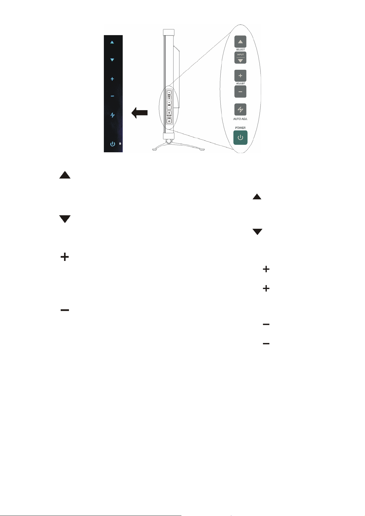
Up Button
1. Activate the On-Screen Display menu.
2. While the On-Screen Display menu appears, press
selected item clockwise or onward.
INPUT / Down Button
to move the
1. While the On-Screen Display menu appears, press
selected item counterclockwise or backward.
Increase Button
1. When the On-Screen Display menu is activated, press
the selected items.
2. When the On-Screen Display menu is activated, press
adjustable value o f th e selected item.
Decrease Button
1. When the On-Screen Display menu is activated, press
the selected item.
2. When the On-Screen Display menu is activated, press to decrease the
adjustable value o f th e selected item.
to move the
to confirm/ enter
to increase the
to confirm/ enter
6
Page 8

Auto Button / Video Mode
1. Press
to select the preferred video mode: User, Text, Movie, Game or
Graphic. The option will toggle on the top right hand corner of the display.
2. Press
for 3 seconds to adjust the picture position and performance
automatically for optimal settings. You are recommended to press the
button the first time you use the display or every time you change the
resolution and/or refresh rate of the input signal.
3. When the On-Screen Display menu is activated, press
at any time.
Power Switch
Turns the display on or off.
LED Indicator
Indicates the display’s operational mode; green for regular operation, and
amber for power saving mode.
Hot Key Input Select Hot key
Pressing
and buttons at the same time for 5 seconds can switch
between auto and manual input select.
When the input select is under manual mode, press
input signal: D-sub, DVI, CVBS or S-Video. The option will toggle on the top
right hand corner of the display.
to exit the menu
to choose the desired
Illuminator Function Hot Key
Press and hold “
” button for 3 seconds to turn the screen to completely white
screen to enable you to use the screen as the light box for the x-ray film. To
change the screen back to normal display mode, simply press and hold “
”
button again for 3 seconds.
7
Page 9

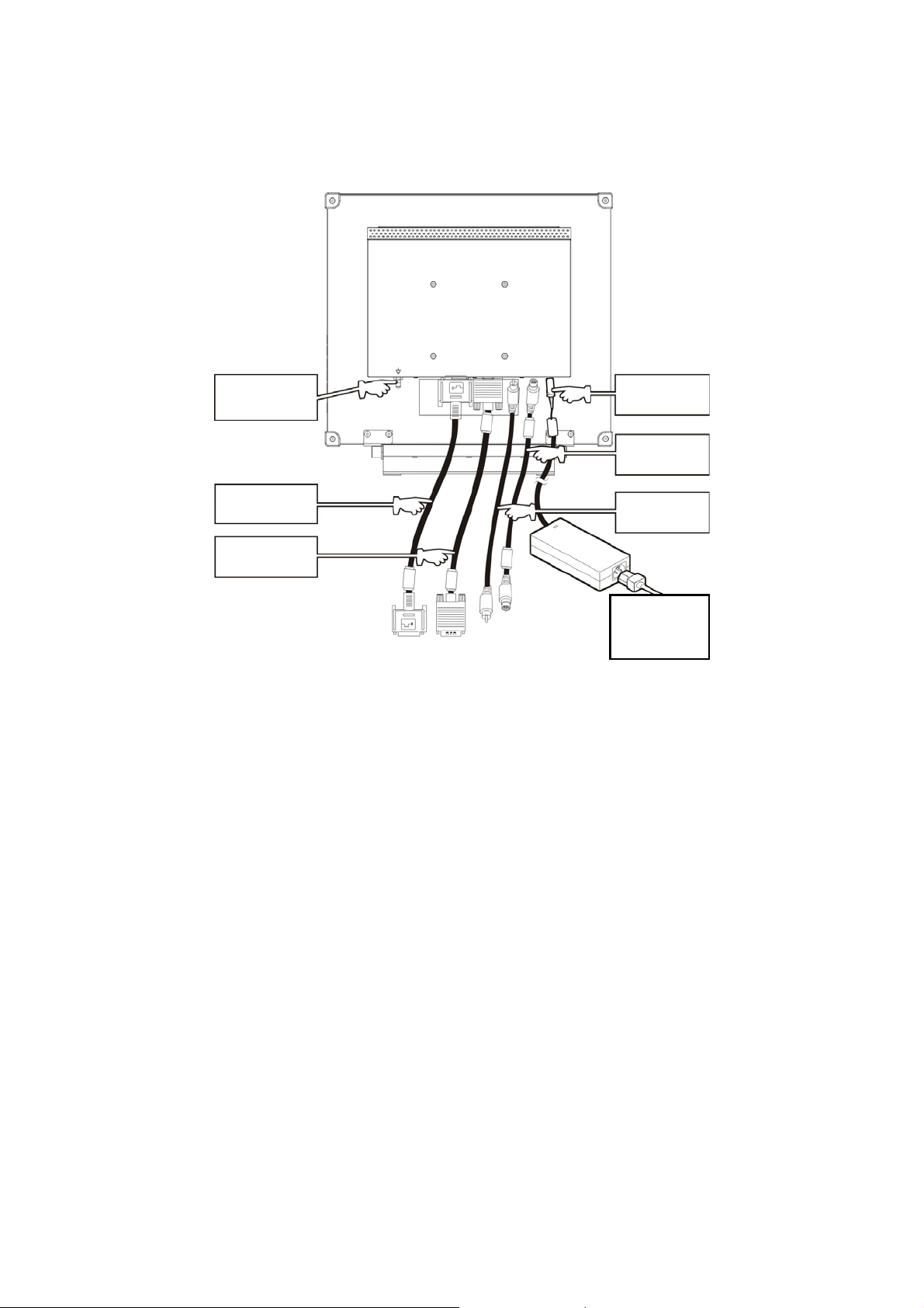
Setup
Please follow the following instructions to setup display.
Step 1: Remove all packing materials and wrapping from the display and then tear down
the plastic dust cover from the screen surface.
Step 2: With the computer or video equipment turned off, connect the enclosed VGA
signal cable.
Connecting to an IBM or IBM compatible computer
Connecting to a video equipment with digital source
Connecting to a video equipment with S-Video connecto r
8
Page 10

Connecting to a video equipment with CVBS jack
Step 3: With the display turned off, connect the display end power plug of adaptor to the
power jack of the display. Then connect the power cord to the adaptor and the
power plug to the power source.
Step 4: Turn on your computer or video equipment. Press power switch to turn on
display.
Step 5: For best performance. (If the display is connected to a video equipment such as
DVD or VCR player, plea se skip this step.)
For DR-17 LCD display, it will have the best performance at resolution 1280 x
1024. Ensure that your computer display is set at 1280 x 1024 pixels and 60Hz.
Press the AUTO button. The display will optimise the display automatic ally.
Installing the X-Ray Film Positioner on Your LCD Panel:
1. Place the x-ray film positioner on the top of the LCD
panel. Align it so that the three positioner’s holes are
on the top of the LCD panel’s ventilation holes as
shown in the illustration.
Be sure that the longer edge of the positioner is placed
at the front side of the LCD panel.
2. Insert the 3 rivets into the positioner’s holes and pass
through the LCD panel’s ventilation holes to secure it.
3. To view the x-ray film image,
attach the x-ray film on the
positioner.
9
Page 11

Customising Your Display
Adjusting Your LCD Panel
In the OSD menu, you will find all kinds of features to help you adjust your LCD panel to the
optimal performance.
User Mode:
To allow preferable viewing images for different tasks, users are able to adjust each setting
manually in User mode.
Text/ Movie/ Game/ Graphic Mode:
The four specialised modes have their own pre-arranged settings for optimal viewing within
each application. To better suit users' needs and environments, Brightness Adjustment and
Contrast Adjus tment a re av ailab le fo r further adjus t men t (Colour tem perature is also adjustable
in Text mode).
Important!
Though manual adjustment of the LCD panel is available, we strongly
recommend you to use the auto adjustment function of the panel. It will
automatica lly t un e y ou r LC D panel to the optimal pe r fo r m an c e. S imply push
the AUTO button for 3 seconds to enable the auto adjustment function.
Additionally, w e recommend you to use the auto adjustment function ever y
time after you have changed the resolution or frequency of your display.
Selecting OSD Features
Step 1. Call Ou t the On-Screen Display Menu
Press to activate On-Screen Display menu.
DVI / D-SUB CVBS / S-Video
Step 2. Adjust the Settings
Press
Press
Press
Press
Press
Step 3. Exit the On-Screen Display Menu
Press
to move the selected item clockwise or onward
to move the selected item counterclockwise or backward.
, to confirm/ enter the selected items.
to increase the adjustable value of the selected item.
to decrease the adjustable value of the selected item.
to exit the On-Screen Display menu at any time.
10
Page 12

OSD Menus
VGA-Input
Brightness Adjustment Contrast Adjustment
Horizontal Position Adjustment Ve rtical Position Adjustment
Sharpness Adjustment OSD Transparency Adjustment
Important!
Sharpness adjustment is not available when:
1. the resolution is set as 1280*1024; or
2. the application is in Text, Movie, Game, or Graphic mode.
11
Page 13

Phase Adjustment Clock Adjustment
Color Temperature Selection Horizontal OSD Position Adjustment
Vertical OSD Position Adjustment T ools Adjustment
Video Mode selection Language Selection
ENG FRADEU SPA
ITA RUS ROM POL
CZE NL
日本語
12
簡中文 繁中文
Page 14

Auto and Input Select Selection Exit Selection
DVI-Input
Important! When DVI-Input is selected, the following adjustments are not available:
horizontal position adjustment
phase adjustment
and clock adjustment.
, vertical position adjustment, sharpness,
Brightness Adjustment Contrast Adjustment
OSD Tr a nsparency Adjustment Color Temperature Selection
13
Page 15

Horizontal OSD Position Adjustment Vertical OSD Position Adjustment
Tools Select ion Video Mode selection
Language Selection Auto and Input Select Selection
ENG FRADEU SPA
ITA RUS ROM POL
CZE NL
日本語
簡中文 繁中文
Exit Selection
14
Page 16

CVBS Input / S-VIDEO Input
Brightness Adjustment Contrast Adjustment
Color Adjustment Hue Adjustment
Sharpness Adjustment OSD Transparency Adjustment
Color Temperature Select ion Horizontal Position Adjustment
15
Page 17

Vertical Position Adjustment Tools Selection
Language Selection Auto and Input Select Selection
ENG FRA DEU SPA
ITA RUS ROM POL
CZE NL
日本語
簡中文 繁中文
Exit Selection
16
Page 18

Warning Messages and Troubleshooting
Warning Messages
If the message appears on the s creen Check the items
CAN NOT DISPLAY THIS INPUT SIGNAL The input signal is not acceptable by the display.
Please check the video resolution and
frequency range is within that specified for
the display.
Please refer to the “Technical Specifications”
section of this user manual for details.
NO SIGNAL INPUT No signal inputs are detected from any one of the
input connectors.
Check that the power switch of your computer or
video source is in the “ON” position.
Check that the signal cable is connected
properly.
Ensure that no pins are bent or pushed in the
connectors of signal cable.
WAIT FOR AUTOMATIC ADJUSTMENT The display is detecting the input signal and then
adjusting automatically the display parameters
accordantly.
It takes around 5 seconds to finish the whole
process.
You are recommended to run auto adjustment
by pressing
time you changed the resolution or refresh
rate.
button for 3 seconds every
17
Page 19

Troubleshooting
Symptom Check Items
No pictur e
Power LED is off.
Check that the power switch of display is turned
on.
Check that the power adaptor is properly
connected to the display.
Check that the power cord is properly connected
to the power adaptor.
Check that the power cord is properly connected to
No display
Power LED is amber
power outlet.
Check there is electrical power coming from the
power outlet. Use another device to check for power.
Check if your PC is in standby mode (move the
mouse or push any key will wake up your PC).
Check if your PC or video source is ON.
Check if the si gnal cable is correct ly connected.
The texts are not solid Change the resolution of the video signal to
1280*1024.
Screen image is not centered
properly.
Some lines are missing
There are red, green, blue or
black tiny dots on the screen.
If the display screen appear to be
completely brigh t wh ite
Press
automatic adjustment.
Adjust Clock and Phase in the O SD menu to fine
tune. (Please refer to the “Customizing Your Display”
section of this user manual for details.)
Press button for 3 seconds to run the
automatic adjustment.
Adjust H. Position and V. Position to fine tune.
(Please refer to the “Customizing Your Display”
section of this user manual for details.)
The TFT LCD panel is made of millions of small
transistors. And each defect transistor will caus e a
missing red, green, or blue dot.
It’s guarantees maxi mum 3 missing dots in every
single display. It’s around the industrial standard.
There is a possibility that the display is in
“Illuminator” mode. Try to change the “Illuminator”
mode back to the normal display mode by press
down “
button for 3 seconds to run the
” button and hold for 3 seconds.
18
Page 20

Specifications
DR-17
Technical Specifications
Panel
Frequency
Power
Panel T ype 17” TFT LCD
Max. Resolution SXGA 1280*1024
Pixel Pitch 0.264mm
Display color 16.2M
(H) 30KHz~80KHz
(V) 56Hz~75Hz
Max. Pixel Clock 140MHz
Rating 24V / 2.0A
Consumption <23W(on),
<5W(stand-by),
<2W(off)
Adaptor AC power cord 1.8 m
DC power cord 5 m
Environmental
Appearance
*The above specifications are subject to change without notice.
Operation condition Temperature 0°~40°
Humidity 10%~90%
Storage condition Temperature -20°~60°
Humidity 5%~95%
Transport Temperature -20°~60°
Humidity 5%~95%
Tilt angle 0°~+15°
VESA mounting 100mm
Dimensions (Net) 408*398*175 mm (W*H*D)
Weight (Net) 6.6 Kg (with base) / 5.9 Kg (w/o base)
19
Page 21

Regulation
FCC compliance
This device complies wit h Part 15 of the FCC Rul es. Operation is subject to the foll owing two
conditions: (1) this device may not cause harmful interference, and (2) this device must accept
any interference received, including interference that may cause undesired operation.
NOTE: This equipment has been tested and found to comply with the limits for a Class B digita l
device, pursuant to Part 15 of the FCC Rules. These limits are designed to provide reasonable
protection against harmful interference in a residential installation. This equipment generates
uses and can radiate radio frequency energy and, if not installed and used in accordance with
the instructions, may cause harmful interference to radio communications. However, there is no
guarantee that interference will not occur in a particular installation. If this equipment does
cause harmful interference to radio or television reception, which can be determined by turning
the equipment off and on, the user is encouraged to try to correct the interference by one or
more of the following measures:
Reorient or relocate the receiving antenna.
Increase the separation between the equipment and receiver.
Connect the equipment to an outlet on a circuit different from that to which the receiver is
connected.
Consult the dealer or an experienced radio/TV technician for help.
WARNING: Any unauthorized modification to this equipment could result in the
revocation of the authorization to operate the equipment and void the
product warranty.
WEEE
Information for users applicable in European Union countries
The symbol on the product or its packaging signifies that this product has to be
disposed separately from ordinary household wastes at its end of life. Please kindly
be aware that this is your responsibility to dispose electronic equipment at recycling
centers so as to help conserve natural resources. Each country in the European
Union should have its collection centers for electrical and electronic equipment
recycling. For information about your recycling drop off area, please contact your
local related electrical and electronic equipment waste management authority or the
retailer where you bought the product.
20
Page 22

Hg
A
A
Lamp Disposal
LAMP(S) inside this product contain mercury and must be recycled or disposed of
according to local, state or federal laws. For more information, contact the electronic
industries alliance at www.eiae.org
www.lamprecycle.org
.
for lamp specific disposal information check
Vermont Hg directive
Title 10: Conservation and Development
Chapter 164: COMPREHENSIV E MERCURY MANAGEMENT
§ 7106. Labeling of mercury-added products
Contains Mercury, Dispose of Properly
Medical Product
EQUIPMENT energized from an external class I power adapter.
According to the degree of protection against electric shock: No applied part.
ccording to the degree of protection against ingress of water as detailed in the
current edition of IEC: IPX0.
ccording to the degree of safety of application in the presence of a
FLAMMABLE ANAESTHETIC MIXTURE WITH AIR or WITH OXYGEN OR
NITROUS OXIDE: EQUIPMENT not suitable for use in the presence of a
FLAMMABLE ANAESTHETIC MIXTURE WITH AIR or WITH OXYGEN OR
NITROUS O XI DE.
According to the mode of operation: CONTINUOUS OPERATION.
The intended application of the LCD monitor is to display.
This 17 inch LCD Monitor intended for using with medical electrical equipments
as an image display.
DR-17 meets to requirement device of the IEC 60601-1-2. If DR-17 is
connected with other medical solutions that must be reevaluated.
The device shall be only connected to IEC 60601-1 approved equipments
within patient environments.
The device shall be only connected to IEC 60950-1 approved equipments
outside patient environments.
The compliance according to IEC 60601-1-1 shall be evaluated for the final
system.
IEC 60601-1 certification is only applicable when using DR-17 together with the
24V adapter that supplied by AG Neovo. If you use any adapter other than 24V
adapter that was supplied with DR-17, then IEC 60601-1 certification will not be
applicable.
21
 Loading...