

查询HLMP-ED16-PP000供应商
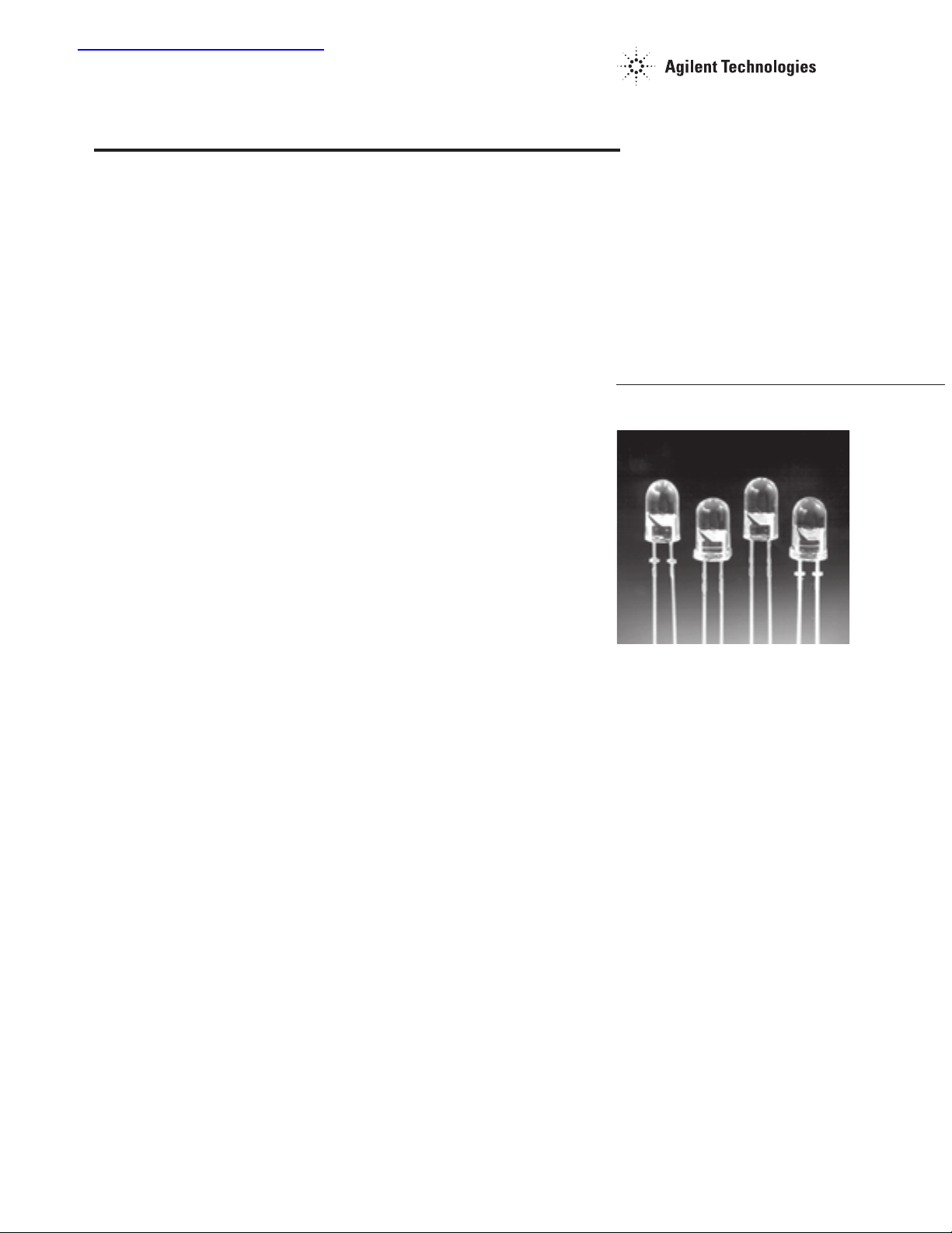
Precision Optical Performance
AlInGaP II LED Lamps
Technical Data
HLMP-ELxx
HLMP-EHxx
HLMP-EDxx
Features
• Well Defined Spatial
Radiation Patterns
• Viewing Angles: 15°,
23°, 30°
• High Luminous Output
• Colors:
592 nm Amber
617 nm Reddish-Orange
630 nm Red
• High Operating Temperature:
T
= +130°C
JLED
• Superior Resistance to
Moisture
Benefits
• Viewing Angles Match Traffic
Management Requirements
• Colors Meet Automotive and
Traffic Signal Specifications
• Superior Light Output
Performance in Outdoor
Environments
• Suitable for Autoinsertion
into PC Boards
Applications
• Traffic Management:
Traffic Signals
Work Zone Warning Lights
Variable Message Signs
• Commercial Outdoor
Advertising:
Signs
Marquees
• Automotive:
Exterior and Interior Lights
Description
Precision Optical Performance
AlInGaP II (aluminum indium
gallium phosphide) LEDs offer
superior light output for
excellent readability in sunlight
and dependable performance.
The AlInGaP II technology
provides extremely stable light
output over long periods of time.
These LED lamps are untinted,
nondiffused, T-13/4 packages
incorporating second generation
optics which produce well
defined radiation patterns at
specific viewing cone angles.
These lamps are made with an
advanced optical grade epoxy
offering superior high temperature and high moisture
resistance performance in
outdoor signal and sign
applications. The maximum LED
junction temperature limit of
+130° C enables high
temperature operation in bright
sunlight conditions. The epoxy
contains both uv-a and uv-b
inhibitors to reduce the effects
of long term exposure to direct
sunlight.
2
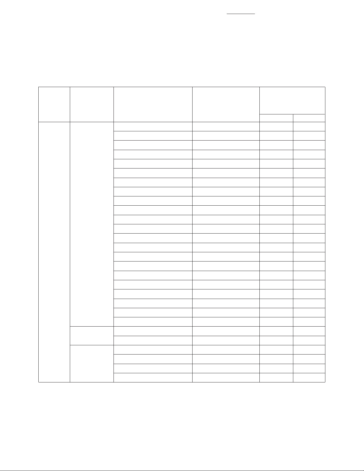
T-13/4 (5 mm) Precision Optical Performance AlInGaP II LED Lamps
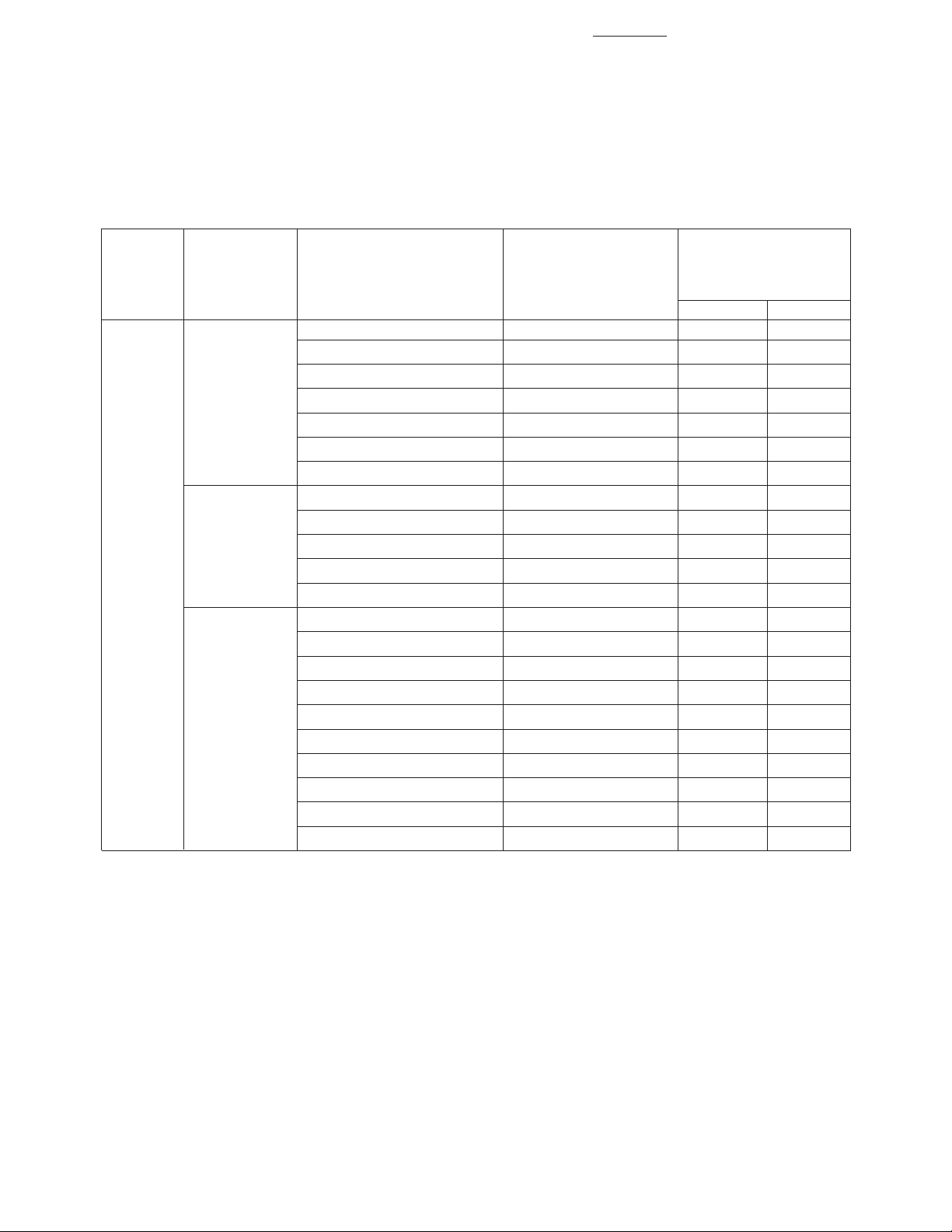
Selection Guide
Typical
Viewing Color and Luminous
Angle Dominant Intensity Iv (mcd)
2θ1/
2
[2]
(Deg.)
15° HLMP-EL16-VWR000 4200 7200
Wavelength Lamps Without Standoffs Lamps With Standoffs @ I(f) = 20 mA
(nm), Typ.
[1]
(Outline Drawing A) (Outline Drawing B)
Min. Max.
HLMP-EL16-TW000 HLMP-EL18-TW000 2500 7200
HLMP-EL16-TWR00 HLMP-EL18-TWR00 2500 7200
HLMP-EL16-TWK00* 2500 7200
HLMP-EL16-TWS00 2500 7200
HLMP-EL16-TUS00 2500 4200
Amber 592 HLMP-EL16-TV400** 2500 5500
HLMP-EL16-TVU00 2500 5500
HLMP-EL16-UX000 HLMP-EL18-UX000 3200 9300
HLMP-EL16-UXR00 HLMP-EL18-UXR00 3200 9300
HLMP-EL16-VW000 4200 7200
HLMP-EL16-VWK00* 4200 7200
HLMP-EL16-VWS00 4200 7200
HLMP-EL16-VX000 4200 9300
HLMP-EL16-VXR00 4200 9300
HLMP-EL16-VX400** 4200 9300
HLMP-EL16-VXK00* 4200 9300
HLMP-EL16-VXS00 4200 9300
HLMP-EL16-VY000 HLMP-EL18-VY000 4200 12000
HLMP-EL16-VYR00 HLMP-EL18-VYR00 4200 12000
HLMP-EL16-VYK00* 4200 12000
HLMP-EL16-VYS00 4200 12000
Red-Orange 615 HLMP-EH18-TW000 2500 7200
HLMP-EH16-UX000 HLMP-EH18-UX000 3200 9300
Red 630 HLMP-ED16-TW000 HLMP-ED18-TW000 2500 7200
HLMP-ED16-TWT00 HLMP-ED18-TWT00 2500 7200
HLMP-ED16-UX000 HLMP-ED18-UX000 3200 9300
HLMP-ED16-UXT00 HLMP-ED18-UXT00 3200 9300
[3,4,5]
3
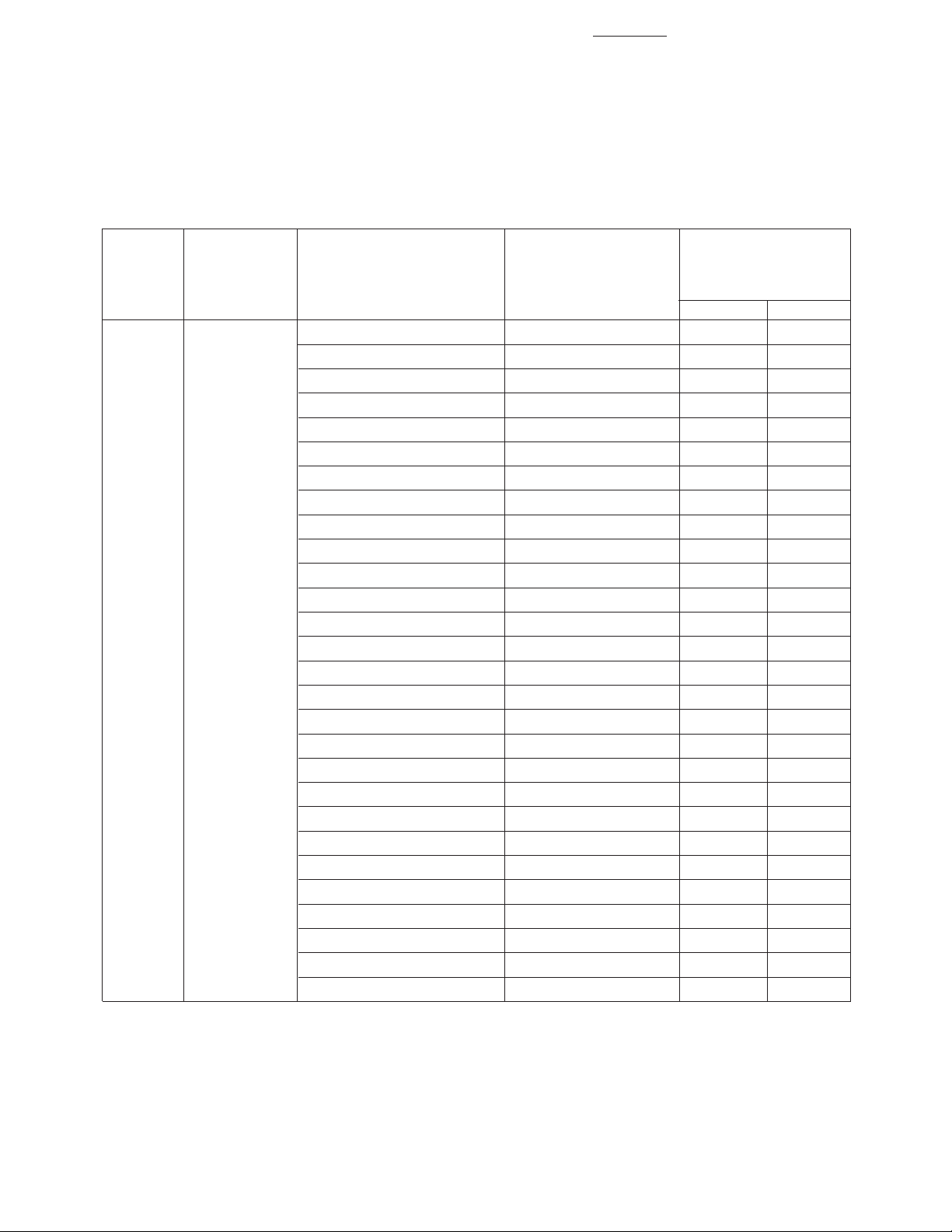
T-13/4 (5 mm) Precision Optical Performance AlInGaP II Led Lamps (Continued)
Selection Guide
Typical
Viewing Color and Luminous
Angle Dominant Intensity Iv (mcd)
2θ1/
2
[2]
(Deg.)
23° Amber 592 HLMP-EL25-RUS00 1500 4200
Wavelength Lamps Without Standoffs Lamps With Standoffs @ I(f) = 20 mA
(nm), Typ.
[1]
(Outline Drawing A) (Outline Drawing B)
Min. Max
HLMP-EL25-QS400** 1150 2500
HLMP-EL25-QSU00 1150 2500
HLMP-EL25-QSK00* 1150 2500
HLMP-EL25-QSS00 1150 2500
HLMP-EL25-QT000 1150 3200
HLMP-EL25-QTR00 HLMP-EL27-QTR00 1150 3200
HLMP-EL25-RU000 HLMP-EL27-RU000 1500 4200
HLMP-EL25-RUR00 HLMP-EL27-RUR00 1500 4200
HLMP-EL25-RUK00* 1500 4200
HLMP-EL25-ST000 1900 3200
HLMP-EL25-STR00 1900 3200
HLMP-EL25-STK00* 1900 3200
HLMP-EL25-STS00 1900 3200
HLMP-EL25-SU000 1900 4200
HLMP-EL25-SUR00 1900 4200
HLMP-EL25-SU400** 1900 4200
HLMP-EL25-SUU00 1900 4200
HLMP-EL25-SUK00* 1900 4200
HLMP-EL25-SUS00 1900 4200
HLMP-EL25-SVK00* 1900 5500
HLMP-EL25-SVS00 1900 5500
HLMP-EL25-SV000 HLMP-EL27-SV000 1900 5500
HLMP-EL25-SVR00 HLMP-EL27-SVR00 1900 5500
HLMP-EL25-TW000 HLMP-EL27-TW000 2500 7200
HLMP-EL25-TWR00 HLMP-EL27-TWR00 2500 7200
HLMP-EL25-TWK00* 2500 7200
HLMP-EL25-TWS00 2500 7200
[3,4]
Notes:
1. Dominant Wavelength, λd, is derived from the CIE Chromaticity Diagram
and represents the color of the lamp.
2. θ
is the off-axis angle where the luminous intensity is one half the on-
1/2
axis intensity.
3. The luminous intensity is measured on the mechanical axis of the lamp
package.
4. The optical axis is closely aligned with the package mechanical axis.
5. Tolerance for each intensity bin limit is ± 15%.
Part numbers in bold are recommended for new designs.
*HLMP-xLxx-xxK00 are selected to amber color bins 2 and 4 only.
**HLMP-xLxx-xx400 are selected to amber color bin 4 only.
4
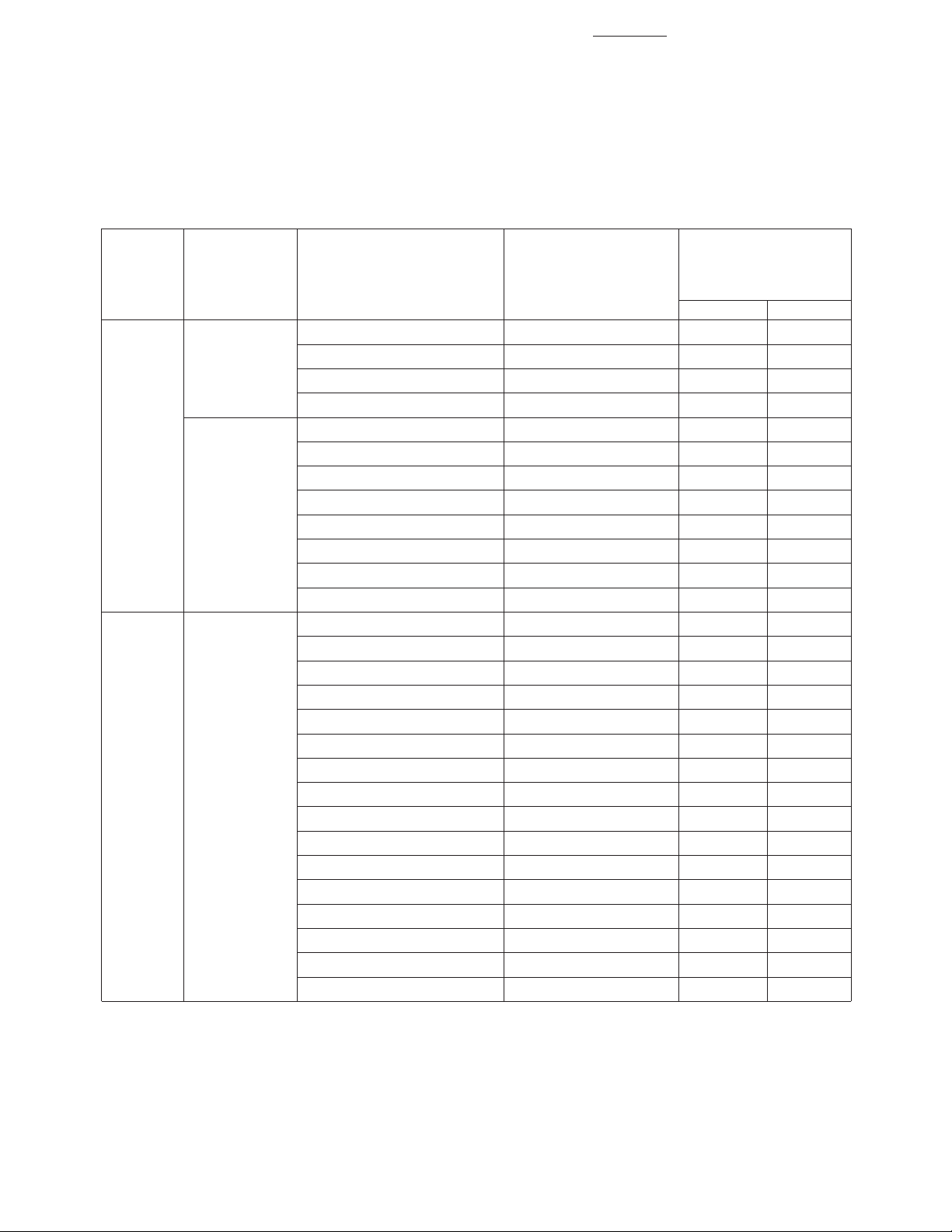
T-13/4 (5 mm) Precision Optical Performance AlInGaP II Led Lamps (Continued)
Selection Guide
Typical
Viewing Color and Luminous
Angle Dominant Intensity Iv (mcd)
2θ1/
2
[2]
(Deg.)
23º HLMP-ED25-QT000 1150 3200
30° Amber 592 HLMP-EL31-QTR00 HLMP-EL33-QTR00 1150 3200
Wavelength Lamps Without Standoffs Lamps With Standoffs @ I(f) = 20 mA
(nm), Typ.
[1]
(Outline Drawing A) (Outline Drawing B)
Min. Max
HLMP-EH25-QT000 1150 3200
Red-Orange 615 HLMP-EH25-RU000 1500 4200
HLMP-EH27-SV000 1900 5500
HLMP-EH25-TW000 HLMP-EH27-TW000 2500 7200
HLMP-ED25-QTT00 1150 3200
Red 630 HLMP-ED25-RU000 HLMP-ED27-RU000 1500 4200
HLMP-ED25-RUT00 HLMP-ED27-RUT00 1500 4200
HLMP-ED25-SV000 HLMP-ED27-SV000 1900 5500
HLMP-ED25-SVT00 HLMP-ED27-SVT00 1900 5500
HLMP-ED25-TW000 HLMP-ED27-TW000 2500 7200
HLMP-ED25-TWT00 HLMP-ED27-TWT00 2500 7200
HLMP-EL31-QRS00 1150 1900
HLMP-EL31-QS000 1150 2500
HLMP-EL31-QSR00 1150 2500
HLMP-EL31-QS400** 1150 2500
HLMP-EL31-QSU00 1150 2500
HLMP-EL31-QT000 HLMP-EL33-QT000 1150 3200
HLMP-EL31-QTK00* 1150 3200
HLMP-EL31-QTS00 1150 3200
HLMP-EL31-SV000 HLMP-EL33-SV000 1900 5500
HLMP-EL31-SVR00 HLMP-EL33-SVR00 1900 5500
HLMP-EL31-ST000 1900 3200
HLMP-EL31-STR00 1900 3200
HLMP-EL31-STK00* 1900 3200
HLMP-EL31-STS00 1900 3200
HLMP-EL31-SUK00* 1900 4200
[3,4]
Notes:
1. Dominant Wavelength, λd, is derived from the CIE Chromaticity
Diagram and represents the color of the lamp.
2. θ
is the off-axis angle where the luminous intensity is one half the
1/2
on-axis intensity.
3. The luminous intensity is measured on the mechanical axis of the
lamp package.
4. The optical axis is closely aligned with the package mechanical axis.
5. Tolerance for each intensity bin limit is ± 15%.
Part numbers in bold are recommended for new designs.
*HLMP-xLxx-xxK00 are selected to amber color bins 2 and 4 only.
**HLMP-xLxx-xx400 are selected to amber color bin 4 only.
5
T-13/4 (5 mm) Precision Optical Performance AlInGaP II Led Lamps (Continued)
Selection Guide
Typical
Viewing Color and Luminous
Angle Dominant Intensity Iv (mcd)
2θ1/
2
[2]
(Deg.)
30° Red-Orange 615 HLMP-EH31-QT000 HLMP-EH33-QT000 1150 3200
Wavelength Lamps Without Standoffs Lamps With Standoffs @ I(f) = 20 mA
(nm), Typ.
[1]
(Outline Drawing A) (Outline Drawing B)
Min. Max.
HLMP-EL31-SUS00 1900 4200
HLMP-EL31-SU400** 1900 4200
Amber 592 HLMP-EL31-SUU00 1900 4200
HLMP-EL31-SU000 1900 4200
HLMP-EL31-SUR00 1900 4200
HLMP-EL31-SVK00* 1900 5500
HLMP-EL31-SVS00 1900 5500
HLMP-EH31-PS000 880 2500
HLMP-EH31-RU000 HLMP-EH33-RU000 1500 4200
HLMP-EH31-SV000 HLMP-EH33-SV000 1900 5500
HLMP-EH31-SU000 1900 4200
HLMP-ED33-QT000 1150 3200
HLMP-ED31-QTT00 HLMP-ED33-QTT00 1150 3200
Red 630 HLMP-ED31-ST000 1900 3200
HLMP-ED31-STT00 1900 3200
HLMP-ED31-SU000 1900 4200
HLMP-ED31-SUT00 1900 4200
HLMP-ED31-RU000 HLMP-ED33-RU000 1500 4200
HLMP-ED31-RUT00 HLMP-ED33-RUT00 1500 4200
HLMP-ED31-SV000 HLMP-ED33-SV000 1900 5500
HLMP-ED31-SVT00 HLMP-ED33-SVT00 1900 5500
[3,4]
Notes:
1. Dominant Wavelength, λd, is derived from the CIE Chromaticity Diagram and
represents the color of the lamp.
2. θ
is the off-axis angle where the luminous intensity is one half the on-
1/2
axis intensity.
3. The luminous intensity is measured on the mechanical axis of the lamp
package.
4. The optical axis is closely aligned with the package mechanical axis.
5. Tolerance for each intensity bin limit is ± 15%.
Part numbers in bold are recommended for new designs.
*HLMP-xLxx-xxK00 are selected to amber color bins 2 and 4 only.
**HLMP-xLxx-xx400 are selected to amber color bin 4 only.

Part Numbering System
HLMP- x x xx - xxxxx
6
Mechanical Options
00: Bulk Packaging
DD: Ammo Pack
YY: Flexi-Bin, Bulk Packaging
ZZ: Flexi-Bin; Ammo Pack
Color Bin & VF Selections
0: No color bin limitation
4: Amber color bin 4 only
K: Amber color bins 2 and 4 only
L: Color bins 4 and 6
R: Amber color bins 1, 2, 4, and 6 with VF max of 2.6 V
S: Amber color bins 2 and 4 with VF max of 2.6 V
T: Red color with VF max of 2.6 V
U: Amber color bin 4 with VF max of 2.6 V
W: Color bins 2, 4 and 6 with VF max of 2.6 V
Y: Color bins 4 and 6 with VF max of 2.6 V
Maximum Intensity Bin
0: No Iv bin limitation
Minimum Intensity Bin
Viewing Angle and Lead Standoffs
16: 15 degree without lead standoffs
18: 15 degree with lead standoffs
25: 23 degree without lead standoffs
27: 23 degree with lead standoffs
31: 30 degree without lead standoffs
33: 30 degree with lead standoffs
Color
D: 630 nm Red
H: 615 nm Red-Orange
L: 592 nm Amber
Package
E: 5 mm Round

Package Dimensions
7
A
31.60
(1.244)
8.71 ± 0.20
(0.343 ± 0.008
MIN.
CATHODE
LEAD
1.00
MIN.
(0.039)
5.00 ± 0.20
(0.197 ± 0.008)
1.14 ± 0.20
(0.045 ± 0.008)
0.70 (0.028)
MAX.
0.50 ± 0.10
(0.020 ± 0.004)
2.35 (0.093)
MAX.
SQ. TYP.
B
31.60
(1.244)
MIN.
CATHODE
1.00
(0.039)
d
LEAD
MIN.
5.00 ± 0.20
(0.197 ± 0.008)
8.71 ± 0.20
(0.343 ± 0.008)
1.50 ± 0.15
(0.059 ± 0.006)
0.70 (0.028)
MAX.
0.50 ± 0.10
(0.020 ± 0.004)
1.14 ± 0.20
(0.045 ± 0.008)
PART NO. d
HLMP-EX18-xxxxx 12.60 ± 0.18
HLMP-EX27-xxxxx 11.59 ± 0.25
HLMP-EX33-xxxxx 11.99 ± 0.25
SQ. TYP.
(0.496 ± 0.007)
(0.446 ± 0.010)
(0.472 ± 0.010)
CATHODE
FLAT
(0.228 ± 0.008)
2.54 ± 0.38
(0.100 ± 0.015)
B
CATHODE
FLAT
5.80 ± 0.20
Absolute Maximum Ratings at TA = 25°C
DC Forward Current
Peak Pulsed Forward Current
Average Forward Current .................................................................30 mA
Reverse Voltage (IR = 100 µA) ................................................................ 5 V
LED Junction Temperature .............................................................. 130°C
Operating Temperature ................................................... -40° C to +100° C
Storage Temperature ....................................................... -40°C to +120° C
Wave Solder Temperature ........................................ 250° C for 3 seconds
Notes:
1. Derate linearly as shown in Figure 4.
2. For long term performance with minimal light output degradation, drive currents
between 10 mA and 30 mA are recommended. For more information on recommended
drive conditions, please refer to Application Brief I-024 (5966-3087E).
3. Please contact your sales representative about operating currents below 10 mA.
[1,2,3]
..................................................................50 mA
[2,3]
................................................. 100 mA
[1.59 mm (0.060 in.) below body]
5.80 ± 0.20
(0.228 ± 0.008)
2.54 ± 0.38
(0.100 ± 0.015)

8
Electrical/Optical Characteristics at TA = 25°C
Parameter Symbol Min. Typ. Max. Units Test Conditions
Forward Voltage IF = 20 mA
Amber (λd = 592 nm) 2.15
Red-Orange (λd = 617 nm) V
F
2.08 2.4
Red (λd = 630 nm) 2.00
Reverse Voltage V
R
520 VI
Peak Wavelength Peak of Wavelength of
Amber 594 Spectral Distribution
Red-Orange λ
PEAK
623 nm at IF = 20 mA
Red 639
Spectral Halfwidth ∆λ
Speed of Response τ
1/2
s
17 nm Wavelength Width at
20 ns Exponential Time
Capacitance C 40 pF VF = 0, f = 1 MHz
Thermal Resistance RΘ
Luminous Efficacy
[2]
J-PIN
240 °C/W LED Junction-to-Cathode
Amber 500 Power/Emitted Radiant
Red-Orange η
v
235 lm/W Power at If = 20 mA
Red 155
[1]
V
= 100 µA
R
Spectral Distribution
1
/2 Power Point at
IF = 20 mA
Constant, e
-t/τ
s
Lead
Emitted Luminous
Notes:
1. For options -xxRxx, -xxSxx, -xxTxx, -xxUxx, -xxWxx, -xxYxx, max forward voltage (Vf) is 2.6 V. Refer to Vf bin table.
2. The radiant intensity, Ie, in watts per steradian, may be found from the equation Ie = Iv/ηv, where Iv is the luminous intensity in candelas and ηv is
the luminous efficacy in lumens/watt.
1.0
0.5
RELATIVE INTENSITY
0
Figure 1. Relative Intensity vs. Peak Wavelength. Figure 2a. Forward Current vs. Forward
AMBER
550 600 650 700
WAVELENGTH – nm
RED-ORANGE
RED
60
50
40
30
20
10
DC FORWARD CURRENT – mA
0
0
0.5 1.5
1.0 2.0
FORWARD VOLTAGE – V
Voltage for Option -xxRxx, -xxSxx, -xxTxx,
-xxUxx, and -xxVxx.
AMBER
RED
2.5
3.0

9
100
90
80
CURRENT – mA
70
60
50
40
30
20
10
0
1.0
1.5 2.0
V
– FORWARD VOLTAGE – V
F
RED
AMBER
2.5
Figure 2b. Forward Current vs. Forward
Voltage.
1.00
0.90
0.80
0.70
0.60
0.50
0.40
0.30
0.20
NORMALIZED INTENSITY – %
0.10
0
-25 -5
2.5
2.0
RED & RED-ORANGE
1.5
1.0
RELATIVE INTENSITY
(NORMALIZED AT 20 mA)
0.5
0
0
3.0
10 30
FORWARD CURRENT – mA
Figure 3. Relative Luminous Intensity vs.
Forward Current.
-20 -15
-10 0 5 10 15 20 25
ANGULAR DISPLACEMENT – DEGREES
AMBER
20 50
40
50
40
RθJA = 585° C/W
30
RθJA = 780° C/W
20
– FORWARD CURRENT – mA
10
F
I
0
0
40 80
20 60 100
T
– AMBIENT TEMPERATURE – °C
A
Figure 4. Maximum Forward Current vs.
Ambient Temperature. Derating Based on
T
= 130°C.
JMAX
Figure 5. Representative Spatial Radiation Pattern for 15° Viewing Angle Lamps.
1.00
0.90
0.80
0.70
0.60
0.50
0.40
0.30
0.20
NORMALIZED INTENSITY – %
0.10
0
-25 -5
-20 -15
-10 0 5 10 15 20 25
ANGULAR DISPLACEMENT – DEGREES
Figure 6. Representative Spatial Radiation Pattern for 24° Viewing Angle Lamps.

1.00
0.90
0.80
0.70
0.60
0.50
0.40
0.30
NORMALIZED INTENSITY
0.20
0.10
0
-20 -15
Figure 7. Representative Spatial Radiation Pattern for 30° Viewing Angle Lamps.
-10 0 5 10 15 20 25-25 -5
ANGULAR DISPLACEMENT – DEGREES
10
Intensity Bin Limits
(mcd at 20 mA)
Bin
Name Min. Max.
P 880 1150
Q 1150 1500
R 1500 1900
S 1900 2500
T 2500 3200
U 3200 4200
V 4200 5500
W 5500 7200
X 7200 9300
Y 9300 12000
Z 12000 16000
Tolerance for each bin limit is ±15%.
Amber Color Bin Limits
(nm at 20 mA)
Bin
Name Min. Max.
1 584.5 587.0
2 587.0 589.5
4 589.5 592.0
6 592.0 594.5
Tolerance for each bin limit is ±0.5 nm.
Note:
1. Bin categories are established for
classification of products. Products
may not be available in all bin
categories.
2. Vf Bin table only available for those
part number with options -xxRxx,
-xxSxx, -xxTxx, -xxUxx, -xxWxx,
-xxYxx.
Vf Bin Table
[2]
Bin
Name Min. Max.
VA 2.0 2.2
VB 2.2 2.4
VC 2.4 2.6
Tolerance for each bin limit is ±0.05 V.
www.agilent.com/semiconductors
For product information and a complete list of
distributors, please go to our web site.
For technical assistance call:
Americas/Canada: +1 (800) 235-0312 or
(916) 788-6763
Europe: +49 (0) 6441 92460
China: 10800 650 0017
Hong Kong: (+65) 6756 2394
India, Australia, New Zealand: (+65) 6755 1939
Japan: (+81 3) 3335-8152 (Domestic/International), or 0120-61-1280 (Domestic Only)
Korea: (+65) 6755 1989
Singapore, Malaysia, Vietnam, Thailand,
Philippines, Indonesia: (+65) 6755 2044
Taiwan: (+65) 6755 1843
Data subject to change.
Copyright © 2004 Agilent Technologies, Inc.
Obsoletes 5988-8601EN
June 23, 2004
5989-0661EN

Copyright © Each Manufacturing Company.
All Datasheets cannot be modified without permission.
This datasheet has been download from :
www.AllDataSheet.com
100% Free DataSheet Search Site.
Free Download.
No Register.
Fast Search System.
www.AllDataSheet.com
 Loading...