

Page 1

Agilent B2200A
Femto Leakage Switch
Mainframe
Agilent B2201A
14ch Low Leakage Switch
Mainframe
User’s Guide
Agilent Technologies
Page 2

Notices
© Agilent Technologies, Inc. 2004, 2005,
2009, 2011
No part of this manual may be reproduced
in any form or by any means (including
electronic storage and retrieval or translation into a foreign language) without prior
agreement and written consent from Agilent Technologies, Inc. as governed by
United States and international copyright
laws.
Manual Part Number
B2200-90000
Edition
Edition 1, October 2004
Edition 2, July 2005
Edition 3, July 2009
Edition 4, August 2011
Agilent Technologies, Inc.
5301 Stevens Creek Blvd
Santa Clara, CA 95051 USA
Warranty
The material contained in this document is provided “as is,” and is subject to being changed, without notice,
in future editions. Further, to the maximum extent permitted by applicable
law, Agilent disclaims all warranties,
either express or implied, with regard
to this manual and any information
contained herein, including but not
limited to the implied warranties of
merchantability and fitness for a particular purpose. Agilent shall not be
liable for errors or for incidental or
consequential damages in connection
with the furnishing, use, or performance of this document or of any
information contained herein. Should
Agilent and the user have a separate
written agreement with warranty
terms covering the material in this
document that conflict with these
terms, the warranty terms in the separate agreement shall control.
Technology Licenses
The hardware and/or software described in
this document are furnished under a
license and may be used or copied only in
accordance with the terms of such license.
receive no greater than Restricted Rights as
defined in FAR 52.227-19(c)(1-2) (June
1987). U.S. Government users will receive
no greater than Limited Rights as defined in
FAR 52.227-14 (June 1987) or DFAR
252.227-7015 (b)(2) (November 1995), as
applicable in any technical data.
Restricted Rights Legend
If software is for use in the performance of
a U.S. Government prime contract or subcontract, Software is delivered and licensed
as “Commercial computer software” as
defined in DFAR 252.227-7014 (June 1995),
or as a “commercial item” as defined in
FAR 2.101(a) or as “Restricted computer
software” as defined in FAR 52.227-19
(June 1987) or any equivalent agency regulation or contract clause. Use, duplication
or disclosure of Software is subject to Agilent Technologies’ standard commercial
license terms, and non-DOD Departments
and Agencies of the U.S. Government will
Page 3

DECLARATION OF CONFORMITY
According to EN ISO/IEC 17050-1:2004
Manufacturer’s Name:
Agilent Technologies Singapore (International) Pte. Ltd.
Manufacturer’s Address:
No. 1 Yishun Ave 7
SINGAPORE 768923
Singapore
Declares under sole responsibility that the product as originally delivered
Product Name:
Femto Leakage Switch Mainframe
Femto Leakage Switch Module
14ch Low Leakage Switch Mainframe
14ch Low Leakage Switch Module
Model Number:
Agilent B2200A
Agilent B2210A
Agilent B2201A
Agilent B2211A
Product Options:
This declaration covers all related options of the above product(s)
complies with the essential requirements of the following applicable European Directives, and carries
the CE marking accordingly:
Low Voltage Directive (2006/95/EC)
EMC Directive (2004/108/EC)
and conforms with the following product standards
EMC Standard
IEC 61326-1:2005 / EN 61326-1:2006
CISPR 11:2003 / EN55011:1998+A1:1999+A2 :2002
IEC 61000-4-2:2001 /EN 61000-4-2:1995+A1:1998+A2:2001
IEC 61000-4-3:2002+A1:2002/EN 61000-4-3:2002+A1:2002
IEC 61000-4-4:2004 / EN 61000-4-4:2004
IEC 61000-4-5:2001/EN 61000-4-5:1995+A1:2001
IEC 61000-4-6:2003 / EN 61000-4-6:1996+A1:2001
IEC 61000-4-11:2004 / EN 61000-4-11:2004
Canada: ICES/NMB-001:2004
Australia/New Zealand: AS/NZS CISPR 11:2004
Limit
Group 1 Class A
4 kV CD, 8 kV AD
3 V/m / 80 MHz-1 GHz / 1.4-2 GHz, 1 V/m / 2-2.7 GHz
0.5 kV signal lines, 1 kV power lines
0.5 kV line-line, 1 kV line-ground
3 V, 0.15-80 MHz
Voltage Dip: 0 % for 1/0.5 cycle, 70 % for 25/30 cycles
Short Interruptions: 0 % for 250/300 cycles
Safety
IEC 61010-1:2001 / EN 61010-1:2001
Canada: CAN/CSA-C22.2 No. 61010-1-04, NRTL/C
Supplementary Information:
The product was tested in a typical configuration with Agilent Technologies test systems.
This DoC applies to above-listed products placed on the EU market after:
Year of the CE marking ‘04
February 22, 2013
Date
Toshiyuki Kawaji
QA Manager
Agilent Technologies
Hachioji Semiconductor Test Division
For further information, please contact your local Agilent Technologies sales office, agent or distributor,
or Agilent Technologies Deutschland GmbH, Herrenberger Straße 130, 71034 Böblingen, Germany.
Page 4

• Herstellerbescheinigung
GERÄUSCHEMISSION
Lpa < 70 dB
am Arbeitsplatz
normaler Betrieb
nach DIN 45635 T. 19
• Manufacturer’s Declaration
ACOUSTIC NOISE EMISSION
Lpa < 70dB
operator position
normal operation
per ISO 7779
NOTE This ISM device complies with Canadian ICES-001.
Cet appareil ISM est conforme à la norme NMB-001 du Canada.
South Korean Class A EMC declaration
This equipment is Class A suitable for professional use and is for use in
electromagnetic environments outside of the home.
Korea’s safety and EMC mark
Page 5

This product complies with the WEEE Directive (2002/96/EC) marking requirements.
The affixed label indicates that you must not discard this electrical/ electronic product
in domestic household waste.
Product Category: With reference to the equipment types in the WEEE Directive
Annex I, this product is classed as a “Monitoring and Control instrumentation”
product.
Do not dispose in domestic household waste.
To return unwanted products, contact your local Agilent office, or see
www.agilent.com/environment/product/ for more information.
Microsoft, Windows, Visual C++, and Visual Basic are registered trademarks of Microsoft Corporation.
Borland C++ Builder is registered trademark of International, Inc. LabWindows and LabVIEW are registered
trademarks of National Instruments Corporation. All other trademarks are the property of their respective
owners.
Page 6

Safety Summary
The following general safety precautions must be observed during all phases of
operation, service, and repair of this instrument. Failure to comply with these
precautions or with specific warnings elsewhere in this manual may impair the
protections provided by the equipment. In addition, it violates safety standards of
design, manufacture, and intended use of the instrument. Agilent Technologies, Inc.
assumes no liability for customer’s failure to comply with these requirements.
NOTE Agilent B2200 complies with INSTALLATION CATEGORY II for mains input and
INSTALLATION CATEGORY I for measurement input terminals, and POLLUTION
DEGREE 2 defined in IEC 61010-1.
Agilent B2200 is INDOOR USE products.
• GROUND THE INSTRUMENT
This is Safety Class I instrument. To minimize shock hazard, the instrument
chassis and cabinet must be connected to an electrical ground. The power
terminal and the power cable must meet International Electrotechnical
Commission (IEC) safety standards.
• DO NOT OPERATE IN AN EXPLOSIVE ATMOSPHERE
Do not operate the instrument in the presence of flammable gases or fumes.
Operation of any electrical instrument in such an environment constitutes a
definite safety hazard.
• KEEP AWAY FROM LIVE CIRCUITS
Operation personnel must not remove instrument covers. Component replacement
and internal adjustments must be made by qualified maintenance personnel. Do
not replace components with power cable connected. Under certain conditions,
dangerous voltages may exist even with the power cable removed. To avoid
injuries, always disconnect power and discharge circuits before touching them.
• DO NOT SERVICE OR ADJUST ALONE
Do not attempt internal service or adjustment unless another person, capable of
rendering first aid and resuscitation, is present.
• DO NOT SUBSTITUTE PARTS OR MODIFY INSTRUMENT
Page 7

Because of the danger of introducing additional hazards, do not install substitute
parts or perform any unauthorized modification to the instrument. Return the
instrument to a Agilent Technologies Sales and Service Office for services and
repair to ensure that safety features are maintained.
• DANGEROUS PROCEDURE WARNINGS
Warnings, such as example below, precede potentially dangerous procedures
throughout this manual. Instructions contained in the warnings must be followed.
WARNING Dangerous Voltage, capable of causing death, are present in this instrument. Use
extreme caution when handling, testing, and adjusting.
Page 8
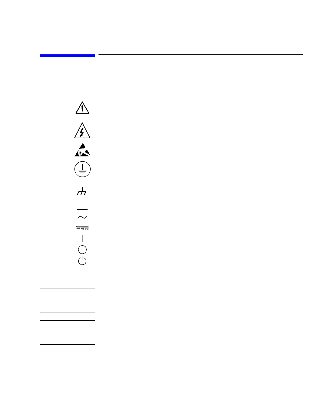
Safety Symbols
The general definitions of safety symbols used on equipment or in manuals are listed
below.
Instruction manual symbol: the product will be marked with this symbol when it is
necessary for the user to refer to the instruction manual in order to protect against
damage to the instrument.
Indicates dangerous voltage and potential for electrical shock. Do not touch terminals
that have this symbol when insrument is on.
Affixed to product containing static sensitive devices--use anti-static handling
procedures to prevent electrostatic discharge damage to component.
Protective conductor terminal. For protection against electrical shock in case of a
fault. Used with field wiring terminals to indicate the terminal which must be
connected to ground before operating equipment.
Frame or chassis terminal. A connection to the frame (chassis) of the equipment
which normally includes all exposed metal structures.
Indicates earth (ground) terminal.
Alternating current.
Direct current.
ON (Supply).
OFF (Supply).
STANDBY (Supply).
CAT 1
WARNING The warning sign denotes a hazard. It calls attention to a procedure, practice,
CAUTION The caution sign denotes a hazard. It calls attention to an operating procedure,
Means INSTALLATION CATEGORY I. Measurement terminals on the rear panel comply
with INSTALLATION CATEGORY I.
condition or the like, which, if not correctly performed or adhered to, could result in
injury or death to personal.
practice, condition or the like, which, if not correctly performed or adhered to, could
result in damage to or destruction of part or all of the product.
Page 9

In This Manual
This manual is a user’s guide for Agilent B2200A/B2201A Switch Mainframe, and
consists of the following chapters:
• Introduction
Describes an overview and specifications of the Agilent B2200 series.
• Installation
Describes how to install the Agilent B2200 and how to setup the input/output.
• Front Panel Operation
Explains the front panel operation and the switch control functions of the Agilent
B2200, also provides the reference information of the front panel keys and display.
• Programming
Explains the programming examples that control the Agilent B2200.
• SCPI Command Reference
Describes the all commands of the Agilent B2200 SCPI commands.
•VXIplug&play Driver
Describes the all functions of the Agilent B2200 VXIplug&play driver.
•Error Messages
Lists and describes the error messages for the Agilent B2200.
Text Conventions
The following text conventions are used in this manual:
Screen Text Represents text that appears on screen of the controller.
Italic Refers to a related document, or is used for emphasis.
Page 10

Page 11

Contents
1. Introduction
Agilent B2200 Series . . . . . . . . . . . . . . . . . . . . . . . . . . . . . . . . . . . . . . . . . . . . . . . . . . . 1-3
Front Panel . . . . . . . . . . . . . . . . . . . . . . . . . . . . . . . . . . . . . . . . . . . . . . . . . . . . . . . . . . . 1-4
. . . . . . . . . . . . . . . . . . . . . . . . . . . . . . . . . . . . . . . . . . . . . . . . . . . . . . . . . . . . . . . . . . . 1-4
Rear Panel. . . . . . . . . . . . . . . . . . . . . . . . . . . . . . . . . . . . . . . . . . . . . . . . . . . . . . . . . . . . 1-6
Switch Modules . . . . . . . . . . . . . . . . . . . . . . . . . . . . . . . . . . . . . . . . . . . . . . . . . . . . . . . 1-8
. . . . . . . . . . . . . . . . . . . . . . . . . . . . . . . . . . . . . . . . . . . . . . . . . . . . . . . . . . . . . . . . . . . 1-8
Specifications . . . . . . . . . . . . . . . . . . . . . . . . . . . . . . . . . . . . . . . . . . . . . . . . . . . . . . . . 1-10
General Specifications . . . . . . . . . . . . . . . . . . . . . . . . . . . . . . . . . . . . . . . . . . . . . . . 1-11
Switch Modules . . . . . . . . . . . . . . . . . . . . . . . . . . . . . . . . . . . . . . . . . . . . . . . . . . . . 1-12
Supplemental Characteristics for B2200A/B2210A . . . . . . . . . . . . . . . . . . . . . . . . 1-13
Supplemental Characteristics for B2201A/B2211A . . . . . . . . . . . . . . . . . . . . . . . 1-14
Accessories and Options . . . . . . . . . . . . . . . . . . . . . . . . . . . . . . . . . . . . . . . . . . . . . . . 1-15
2. Installation
. . . . . . . . . . . . . . . . . . . . . . . . . . . . . . . . . . . . . . . . . . . . . . . . . . . . . . . . . . . . . . . . . . . 2-2
Requirements . . . . . . . . . . . . . . . . . . . . . . . . . . . . . . . . . . . . . . . . . . . . . . . . . . . . . . . . . 2-3
Power Requirements . . . . . . . . . . . . . . . . . . . . . . . . . . . . . . . . . . . . . . . . . . . . . . . . . 2-3
Power Cable . . . . . . . . . . . . . . . . . . . . . . . . . . . . . . . . . . . . . . . . . . . . . . . . . . . . . . . . 2-3
Operating Environment . . . . . . . . . . . . . . . . . . . . . . . . . . . . . . . . . . . . . . . . . . . . . . . 2-5
Storage and Shipping Environment . . . . . . . . . . . . . . . . . . . . . . . . . . . . . . . . . . . . . 2-5
Inspection . . . . . . . . . . . . . . . . . . . . . . . . . . . . . . . . . . . . . . . . . . . . . . . . . . . . . . . . . . . . 2-6
Installing the B2200 . . . . . . . . . . . . . . . . . . . . . . . . . . . . . . . . . . . . . . . . . . . . . . . . . . . 2-7
To Set the GPIB Address . . . . . . . . . . . . . . . . . . . . . . . . . . . . . . . . . . . . . . . . . . . . . . 2-8
To Connect the GPIB Cable . . . . . . . . . . . . . . . . . . . . . . . . . . . . . . . . . . . . . . . . . . . . 2-8
To Install the Switch Module . . . . . . . . . . . . . . . . . . . . . . . . . . . . . . . . . . . . . . . . . . . 2-9
. . . . . . . . . . . . . . . . . . . . . . . . . . . . . . . . . . . . . . . . . . . . . . . . . . . . . . . . . . . . . . . . . . . 2-9
To Install the Blank Panel . . . . . . . . . . . . . . . . . . . . . . . . . . . . . . . . . . . . . . . . . . . . . 2-9
Agilent B2200 User’s Guide, Edition 4
Page 12

Contents
Self-Test. . . . . . . . . . . . . . . . . . . . . . . . . . . . . . . . . . . . . . . . . . . . . . . . . . . . . . . . . . . . . 2-10
Output Connections . . . . . . . . . . . . . . . . . . . . . . . . . . . . . . . . . . . . . . . . . . . . . . . . . . . 2-11
Output Connectors . . . . . . . . . . . . . . . . . . . . . . . . . . . . . . . . . . . . . . . . . . . . . . . . . . 2-11
Connector Plates. . . . . . . . . . . . . . . . . . . . . . . . . . . . . . . . . . . . . . . . . . . . . . . . . . . . 2-12
To Make Connections to DUT Interface. . . . . . . . . . . . . . . . . . . . . . . . . . . . . . . . . . 2-13
To Make Interlock Circuit . . . . . . . . . . . . . . . . . . . . . . . . . . . . . . . . . . . . . . . . . . . . . 2-15
To Mount Connectors . . . . . . . . . . . . . . . . . . . . . . . . . . . . . . . . . . . . . . . . . . . . . . . . 2-18
Input Connections. . . . . . . . . . . . . . . . . . . . . . . . . . . . . . . . . . . . . . . . . . . . . . . . . . . . . 2-20
Measurement Cable Length . . . . . . . . . . . . . . . . . . . . . . . . . . . . . . . . . . . . . . . . . . . . 2-23
Maintenance . . . . . . . . . . . . . . . . . . . . . . . . . . . . . . . . . . . . . . . . . . . . . . . . . . . . . . . . . 2-25
Calibration . . . . . . . . . . . . . . . . . . . . . . . . . . . . . . . . . . . . . . . . . . . . . . . . . . . . . . . . . 2-25
Cleaning . . . . . . . . . . . . . . . . . . . . . . . . . . . . . . . . . . . . . . . . . . . . . . . . . . . . . . . . . . 2-25
3. Front Panel Operation
Operation . . . . . . . . . . . . . . . . . . . . . . . . . . . . . . . . . . . . . . . . . . . . . . . . . . . . . . . . . . . . . 3-3
To Initialize Agilent B2200 . . . . . . . . . . . . . . . . . . . . . . . . . . . . . . . . . . . . . . . . . . . . . 3-4
To Enable Light Pen . . . . . . . . . . . . . . . . . . . . . . . . . . . . . . . . . . . . . . . . . . . . . . . . . . 3-4
To Change Channel Configuration Mode . . . . . . . . . . . . . . . . . . . . . . . . . . . . . . . . . . 3-4
To Change Connection Rule . . . . . . . . . . . . . . . . . . . . . . . . . . . . . . . . . . . . . . . . . . . . 3-5
To Change Connection Sequence . . . . . . . . . . . . . . . . . . . . . . . . . . . . . . . . . . . . . . . 3-5
To Control Switch Condition . . . . . . . . . . . . . . . . . . . . . . . . . . . . . . . . . . . . . . . . . . . . 3-5
To Open All Switches . . . . . . . . . . . . . . . . . . . . . . . . . . . . . . . . . . . . . . . . . . . . . . . . . 3-6
To Save/Load Setup Data. . . . . . . . . . . . . . . . . . . . . . . . . . . . . . . . . . . . . . . . . . . . . . 3-6
To Use Bias Mode . . . . . . . . . . . . . . . . . . . . . . . . . . . . . . . . . . . . . . . . . . . . . . . . . . . . 3-7
To Use Ground Mode . . . . . . . . . . . . . . . . . . . . . . . . . . . . . . . . . . . . . . . . . . . . . . . . . 3-8
To Use Couple Mode . . . . . . . . . . . . . . . . . . . . . . . . . . . . . . . . . . . . . . . . . . . . . . . . . . 3-9
To Display Firmware Revision. . . . . . . . . . . . . . . . . . . . . . . . . . . . . . . . . . . . . . . . . . . 3-9
To Display Module Information . . . . . . . . . . . . . . . . . . . . . . . . . . . . . . . . . . . . . . . . . 3-9
To Read Error Message. . . . . . . . . . . . . . . . . . . . . . . . . . . . . . . . . . . . . . . . . . . . . . . 3-10
To Set Beeper . . . . . . . . . . . . . . . . . . . . . . . . . . . . . . . . . . . . . . . . . . . . . . . . . . . . . . 3-10
Agilent B2200 User’s Guide, Edition 4
Page 13

Contents
To Set GPIB Address . . . . . . . . . . . . . . . . . . . . . . . . . . . . . . . . . . . . . . . . . . . . . . . . 3-10
To Set Remote Display Mode . . . . . . . . . . . . . . . . . . . . . . . . . . . . . . . . . . . . . . . . . . 3-11
To Return to Local Mode . . . . . . . . . . . . . . . . . . . . . . . . . . . . . . . . . . . . . . . . . . . . . 3-11
Switch Control Functions . . . . . . . . . . . . . . . . . . . . . . . . . . . . . . . . . . . . . . . . . . . . . . 3-12
Channel Configuration Mode . . . . . . . . . . . . . . . . . . . . . . . . . . . . . . . . . . . . . . . . . . 3-13
Connection Rule . . . . . . . . . . . . . . . . . . . . . . . . . . . . . . . . . . . . . . . . . . . . . . . . . . . . 3-14
Connection Sequence . . . . . . . . . . . . . . . . . . . . . . . . . . . . . . . . . . . . . . . . . . . . . . . 3-15
Bias Mode . . . . . . . . . . . . . . . . . . . . . . . . . . . . . . . . . . . . . . . . . . . . . . . . . . . . . . . . 3-16
Ground Mode . . . . . . . . . . . . . . . . . . . . . . . . . . . . . . . . . . . . . . . . . . . . . . . . . . . . . . 3-18
Couple Mode . . . . . . . . . . . . . . . . . . . . . . . . . . . . . . . . . . . . . . . . . . . . . . . . . . . . . . 3-20
Display Functions . . . . . . . . . . . . . . . . . . . . . . . . . . . . . . . . . . . . . . . . . . . . . . . . . . . . . 3-22
LED Matrix. . . . . . . . . . . . . . . . . . . . . . . . . . . . . . . . . . . . . . . . . . . . . . . . . . . . . . . . . 3-22
LCD . . . . . . . . . . . . . . . . . . . . . . . . . . . . . . . . . . . . . . . . . . . . . . . . . . . . . . . . . . . . . . 3-23
Front Panel Keys. . . . . . . . . . . . . . . . . . . . . . . . . . . . . . . . . . . . . . . . . . . . . . . . . . . . . . 3-25
Function key group . . . . . . . . . . . . . . . . . . . . . . . . . . . . . . . . . . . . . . . . . . . . . . . . . . 3-26
Edit key group . . . . . . . . . . . . . . . . . . . . . . . . . . . . . . . . . . . . . . . . . . . . . . . . . . . . . . 3-29
Setup Menus. . . . . . . . . . . . . . . . . . . . . . . . . . . . . . . . . . . . . . . . . . . . . . . . . . . . . . . . . 3-30
Setup Menu. . . . . . . . . . . . . . . . . . . . . . . . . . . . . . . . . . . . . . . . . . . . . . . . . . . . . . . . 3-30
Selftest Menu . . . . . . . . . . . . . . . . . . . . . . . . . . . . . . . . . . . . . . . . . . . . . . . . . . . . . . 3-34
4. Programming
Programming Basics . . . . . . . . . . . . . . . . . . . . . . . . . . . . . . . . . . . . . . . . . . . . . . . . . . . 4-3
SCPI Command Hierarchy . . . . . . . . . . . . . . . . . . . . . . . . . . . . . . . . . . . . . . . . . . . . . 4-3
Fundamental Commands . . . . . . . . . . . . . . . . . . . . . . . . . . . . . . . . . . . . . . . . . . . . . . 4-4
Switch Control . . . . . . . . . . . . . . . . . . . . . . . . . . . . . . . . . . . . . . . . . . . . . . . . . . . . . . 4-5
Programming Examples . . . . . . . . . . . . . . . . . . . . . . . . . . . . . . . . . . . . . . . . . . . . . . . . . 4-7
Connecting Input-Output Paths . . . . . . . . . . . . . . . . . . . . . . . . . . . . . . . . . . . . . . . . . 4-8
Using Bias Mode . . . . . . . . . . . . . . . . . . . . . . . . . . . . . . . . . . . . . . . . . . . . . . . . . . . 4-10
Using Ground Mode . . . . . . . . . . . . . . . . . . . . . . . . . . . . . . . . . . . . . . . . . . . . . . . . . 4-12
Agilent B2200 User’s Guide, Edition 4
Page 14

Contents
Using Couple Mode. . . . . . . . . . . . . . . . . . . . . . . . . . . . . . . . . . . . . . . . . . . . . . . . . . 4-14
Saving Input/Output Labels . . . . . . . . . . . . . . . . . . . . . . . . . . . . . . . . . . . . . . . . . . . 4-16
Defining Comment for Internal Memory . . . . . . . . . . . . . . . . . . . . . . . . . . . . . . . . . 4-18
Capacitance Compensation . . . . . . . . . . . . . . . . . . . . . . . . . . . . . . . . . . . . . . . . . . . . . 4-20
Capacitance Compensation Function . . . . . . . . . . . . . . . . . . . . . . . . . . . . . . . . . . . 4-20
Required Conditions . . . . . . . . . . . . . . . . . . . . . . . . . . . . . . . . . . . . . . . . . . . . . . . . . 4-21
To Create Compensation Data File . . . . . . . . . . . . . . . . . . . . . . . . . . . . . . . . . . . . . . 4-23
To Perform Measurement and Compensation. . . . . . . . . . . . . . . . . . . . . . . . . . . . . 4-27
5. SCPI Command Reference
Common Commands . . . . . . . . . . . . . . . . . . . . . . . . . . . . . . . . . . . . . . . . . . . . . . . . . . . 5-4
Commands Summary . . . . . . . . . . . . . . . . . . . . . . . . . . . . . . . . . . . . . . . . . . . . . . . . . 5-4
*CLS . . . . . . . . . . . . . . . . . . . . . . . . . . . . . . . . . . . . . . . . . . . . . . . . . . . . . . . . . . . . . .5-5
*ESE . . . . . . . . . . . . . . . . . . . . . . . . . . . . . . . . . . . . . . . . . . . . . . . . . . . . . . . . . . . . . .5-5
*ESR? . . . . . . . . . . . . . . . . . . . . . . . . . . . . . . . . . . . . . . . . . . . . . . . . . . . . . . . . . . . . .5-6
*IDN? . . . . . . . . . . . . . . . . . . . . . . . . . . . . . . . . . . . . . . . . . . . . . . . . . . . . . . . . . . . . . .5-7
*OPC . . . . . . . . . . . . . . . . . . . . . . . . . . . . . . . . . . . . . . . . . . . . . . . . . . . . . . . . . . . . . .5-8
*RST . . . . . . . . . . . . . . . . . . . . . . . . . . . . . . . . . . . . . . . . . . . . . . . . . . . . . . . . . . . . . .5-9
*SRE . . . . . . . . . . . . . . . . . . . . . . . . . . . . . . . . . . . . . . . . . . . . . . . . . . . . . . . . . . . . . 5-10
*STB? . . . . . . . . . . . . . . . . . . . . . . . . . . . . . . . . . . . . . . . . . . . . . . . . . . . . . . . . . . . . 5-11
*TST? . . . . . . . . . . . . . . . . . . . . . . . . . . . . . . . . . . . . . . . . . . . . . . . . . . . . . . . . . . . . . 5-12
*WAI . . . . . . . . . . . . . . . . . . . . . . . . . . . . . . . . . . . . . . . . . . . . . . . . . . . . . . . . . . . . . 5-12
Subsystem Commands . . . . . . . . . . . . . . . . . . . . . . . . . . . . . . . . . . . . . . . . . . . . . . . . . 5-13
Command Summary . . . . . . . . . . . . . . . . . . . . . . . . . . . . . . . . . . . . . . . . . . . . . . . . . 5-13
:DIAGnostic:TEST:CARD:CLEar . . . . . . . . . . . . . . . . . . . . . . . . . . . . . . . . . . . . . . . . 5-21
:DIAGnostic:TEST:CARD[:EXECute]? . . . . . . . . . . . . . . . . . . . . . . . . . . . . . . . . . . . . 5-21
:DIAGnostic:TEST:CARD:STATe? . . . . . . . . . . . . . . . . . . . . . . . . . . . . . . . . . . . . . . . 5-21
:DIAGnostic:TEST:FRAMe:CLEar . . . . . . . . . . . . . . . . . . . . . . . . . . . . . . . . . . . . . . . 5-22
:DIAGnostic:TEST:FRAMe[:EXECute]? . . . . . . . . . . . . . . . . . . . . . . . . . . . . . . . . . . 5-22
:DIAGnostic:TEST:FRAMe:STATe? . . . . . . . . . . . . . . . . . . . . . . . . . . . . . . . . . . . . . . 5-23
[:ROUTe]:AGND:CHANnel:DISable:CARD . . . . . . . . . . . . . . . . . . . . . . . . . . . . . . . . 5-24
Agilent B2200 User’s Guide, Edition 4
Page 15

Contents
[:ROUTe]:AGND:CHANnel:DISable[:LIST] . . . . . . . . . . . . . . . . . . . . . . . . . . . . . . . . 5-24
[:ROUTe]:AGND:CHANnel:ENABle:CARD . . . . . . . . . . . . . . . . . . . . . . . . . . . . . . . . 5-25
[:ROUTe]:AGND:CHANnel:ENABle[:LIST] . . . . . . . . . . . . . . . . . . . . . . . . . . . . . . . . 5-25
[:ROUTe]:AGND:PORT . . . . . . . . . . . . . . . . . . . . . . . . . . . . . . . . . . . . . . . . . . . . . . . . 5-26
[:ROUTe]:AGND[:STATe] . . . . . . . . . . . . . . . . . . . . . . . . . . . . . . . . . . . . . . . . . . . . . . 5-27
[:ROUTe]:AGND:UNUSED . . . . . . . . . . . . . . . . . . . . . . . . . . . . . . . . . . . . . . . . . . . . . 5-28
[:ROUTe]:BIAS:CHANnel:DISable:CARD . . . . . . . . . . . . . . . . . . . . . . . . . . . . . . . . . 5-29
[:ROUTe]:BIAS:CHANnel:DISable[:LIST] . . . . . . . . . . . . . . . . . . . . . . . . . . . . . . . . . 5-29
[:ROUTe]:BIAS:CHANnel:ENABle:CARD . . . . . . . . . . . . . . . . . . . . . . . . . . . . . . . . . 5-30
[:ROUTe]:BIAS:CHANnel:ENABle[:LIST] . . . . . . . . . . . . . . . . . . . . . . . . . . . . . . . . . 5-30
[:ROUTe]:BIAS:PORT . . . . . . . . . . . . . . . . . . . . . . . . . . . . . . . . . . . . . . . . . . . . . . . . 5-31
[:ROUTe]:BIAS[:STATe] . . . . . . . . . . . . . . . . . . . . . . . . . . . . . . . . . . . . . . . . . . . . . . 5-32
[:ROUTe]:CLOSe:CARD? . . . . . . . . . . . . . . . . . . . . . . . . . . . . . . . . . . . . . . . . . . . . . . 5-33
[:ROUTe]:CLOSe[:LIST] . . . . . . . . . . . . . . . . . . . . . . . . . . . . . . . . . . . . . . . . . . . . . . . 5-33
[:ROUTe]:CONNection:RULE . . . . . . . . . . . . . . . . . . . . . . . . . . . . . . . . . . . . . . . . . . 5-34
[:ROUTe]:CONNection:SEQuence . . . . . . . . . . . . . . . . . . . . . . . . . . . . . . . . . . . . . . 5-34
[:ROUTe]:COUPle:PORT . . . . . . . . . . . . . . . . . . . . . . . . . . . . . . . . . . . . . . . . . . . . . . 5-35
[:ROUTe]:COUPle:PORT:DETect . . . . . . . . . . . . . . . . . . . . . . . . . . . . . . . . . . . . . . . . 5-36
[:ROUTe]:COUPle[:STATe] . . . . . . . . . . . . . . . . . . . . . . . . . . . . . . . . . . . . . . . . . . . . 5-37
[:ROUTe]:FUNCtion . . . . . . . . . . . . . . . . . . . . . . . . . . . . . . . . . . . . . . . . . . . . . . . . . . 5-38
[:ROUTe]:OPEN:CARD . . . . . . . . . . . . . . . . . . . . . . . . . . . . . . . . . . . . . . . . . . . . . . . 5-38
[:ROUTe]:OPEN[:LIST] . . . . . . . . . . . . . . . . . . . . . . . . . . . . . . . . . . . . . . . . . . . . . . . . 5-39
[:ROUTe]:SYMBol:CHANnel . . . . . . . . . . . . . . . . . . . . . . . . . . . . . . . . . . . . . . . . . . . 5-39
[:ROUTe]:SYMBol:PORT . . . . . . . . . . . . . . . . . . . . . . . . . . . . . . . . . . . . . . . . . . . . . . 5-40
:SYSTem:BEEP . . . . . . . . . . . . . . . . . . . . . . . . . . . . . . . . . . . . . . . . . . . . . . . . . . . . . 5-41
:SYSTem:CCONfig? . . . . . . . . . . . . . . . . . . . . . . . . . . . . . . . . . . . . . . . . . . . . . . . . . . 5-41
:SYSTem:CDEScription? . . . . . . . . . . . . . . . . . . . . . . . . . . . . . . . . . . . . . . . . . . . . . . 5-42
:SYSTem:CPON . . . . . . . . . . . . . . . . . . . . . . . . . . . . . . . . . . . . . . . . . . . . . . . . . . . . . 5-43
:SYSTem:CTYPe? . . . . . . . . . . . . . . . . . . . . . . . . . . . . . . . . . . . . . . . . . . . . . . . . . . . 5-44
:SYSTem:DISPlay:LCD . . . . . . . . . . . . . . . . . . . . . . . . . . . . . . . . . . . . . . . . . . . . . . . . 5-44
:SYSTem:DISPlay:LED . . . . . . . . . . . . . . . . . . . . . . . . . . . . . . . . . . . . . . . . . . . . . . . . 5-45
:SYSTem:DISPlay:STRing . . . . . . . . . . . . . . . . . . . . . . . . . . . . . . . . . . . . . . . . . . . . . 5-45
Agilent B2200 User’s Guide, Edition 4
Page 16

Contents
:SYSTem:ERRor? . . . . . . . . . . . . . . . . . . . . . . . . . . . . . . . . . . . . . . . . . . . . . . . . . . . . 5-46
:SYSTem:KLC . . . . . . . . . . . . . . . . . . . . . . . . . . . . . . . . . . . . . . . . . . . . . . . . . . . . . . . 5-46
:SYSTem:MEMOry:COMMent . . . . . . . . . . . . . . . . . . . . . . . . . . . . . . . . . . . . . . . . . . 5-47
:SYSTem:MEMOry:DELete . . . . . . . . . . . . . . . . . . . . . . . . . . . . . . . . . . . . . . . . . . . . 5-47
:SYSTem:MEMOry:LOAD. . . . . . . . . . . . . . . . . . . . . . . . . . . . . . . . . . . . . . . . . . . . . . 5-48
:SYSTem:MEMOry:SAVE . . . . . . . . . . . . . . . . . . . . . . . . . . . . . . . . . . . . . . . . . . . . . . 5-48
:SYSTem:PEN . . . . . . . . . . . . . . . . . . . . . . . . . . . . . . . . . . . . . . . . . . . . . . . . . . . . . . 5-49
:SYSTem:VERSion? . . . . . . . . . . . . . . . . . . . . . . . . . . . . . . . . . . . . . . . . . . . . . . . . . . 5-49
Status Reporting Structure . . . . . . . . . . . . . . . . . . . . . . . . . . . . . . . . . . . . . . . . . . . . . 5-50
Status Reporting Structure. . . . . . . . . . . . . . . . . . . . . . . . . . . . . . . . . . . . . . . . . . . . 5-50
Status Byte Register . . . . . . . . . . . . . . . . . . . . . . . . . . . . . . . . . . . . . . . . . . . . . . . . 5-52
Service Request Enable Register . . . . . . . . . . . . . . . . . . . . . . . . . . . . . . . . . . . . . . 5-54
Standard Event Status Register . . . . . . . . . . . . . . . . . . . . . . . . . . . . . . . . . . . . . . . 5-55
Standard Event Status Enable Register . . . . . . . . . . . . . . . . . . . . . . . . . . . . . . . . . 5-56
Output Queue . . . . . . . . . . . . . . . . . . . . . . . . . . . . . . . . . . . . . . . . . . . . . . . . . . . . . . 5-57
6. VXIplug&play Driver
System Requirements. . . . . . . . . . . . . . . . . . . . . . . . . . . . . . . . . . . . . . . . . . . . . . . . . . . 6-3
Installing VXIplug&play Driver . . . . . . . . . . . . . . . . . . . . . . . . . . . . . . . . . . . . . . . . . . . . 6-4
Driver Functions . . . . . . . . . . . . . . . . . . . . . . . . . . . . . . . . . . . . . . . . . . . . . . . . . . . . . . . 6-5
agb220xa_biasChanCard . . . . . . . . . . . . . . . . . . . . . . . . . . . . . . . . . . . . . . . . . . . . . . 6-7
agb220xa_biasChanList . . . . . . . . . . . . . . . . . . . . . . . . . . . . . . . . . . . . . . . . . . . . . . . 6-7
agb220xa_biasChanList_Q . . . . . . . . . . . . . . . . . . . . . . . . . . . . . . . . . . . . . . . . . . . . . 6-8
agb220xa_biasPort . . . . . . . . . . . . . . . . . . . . . . . . . . . . . . . . . . . . . . . . . . . . . . . . . . . 6-8
agb220xa_biasState . . . . . . . . . . . . . . . . . . . . . . . . . . . . . . . . . . . . . . . . . . . . . . . . . . 6-9
agb220xa_close. . . . . . . . . . . . . . . . . . . . . . . . . . . . . . . . . . . . . . . . . . . . . . . . . . . . . . 6-9
agb220xa_closeCard_Q . . . . . . . . . . . . . . . . . . . . . . . . . . . . . . . . . . . . . . . . . . . . . . 6-10
agb220xa_closeList. . . . . . . . . . . . . . . . . . . . . . . . . . . . . . . . . . . . . . . . . . . . . . . . . . 6-10
agb220xa_closeList_Q . . . . . . . . . . . . . . . . . . . . . . . . . . . . . . . . . . . . . . . . . . . . . . . 6-10
agb220xa_cmd . . . . . . . . . . . . . . . . . . . . . . . . . . . . . . . . . . . . . . . . . . . . . . . . . . . . . 6-11
Agilent B2200 User’s Guide, Edition 4
Page 17

Contents
agb220xa_cmdData_Q . . . . . . . . . . . . . . . . . . . . . . . . . . . . . . . . . . . . . . . . . . . . . . . 6-11
agb220xa_cmdInt . . . . . . . . . . . . . . . . . . . . . . . . . . . . . . . . . . . . . . . . . . . . . . . . . . . 6-12
agb220xa_cmdInt16Arr_Q . . . . . . . . . . . . . . . . . . . . . . . . . . . . . . . . . . . . . . . . . . . . 6-12
agb220xa_cmdInt16_Q . . . . . . . . . . . . . . . . . . . . . . . . . . . . . . . . . . . . . . . . . . . . . . . 6-12
agb220xa_cmdInt32Arr_Q . . . . . . . . . . . . . . . . . . . . . . . . . . . . . . . . . . . . . . . . . . . . 6-13
agb220xa_cmdInt32_Q . . . . . . . . . . . . . . . . . . . . . . . . . . . . . . . . . . . . . . . . . . . . . . . 6-13
agb220xa_cmdReal. . . . . . . . . . . . . . . . . . . . . . . . . . . . . . . . . . . . . . . . . . . . . . . . . . 6-14
agb220xa_cmdReal64Arr_Q. . . . . . . . . . . . . . . . . . . . . . . . . . . . . . . . . . . . . . . . . . . 6-14
agb220xa_cmdReal64_Q . . . . . . . . . . . . . . . . . . . . . . . . . . . . . . . . . . . . . . . . . . . . . 6-14
agb220xa_cmdString_Q . . . . . . . . . . . . . . . . . . . . . . . . . . . . . . . . . . . . . . . . . . . . . . 6-15
agb220xa_compenC . . . . . . . . . . . . . . . . . . . . . . . . . . . . . . . . . . . . . . . . . . . . . . . . . 6-15
agb220xa_connRuleSeq . . . . . . . . . . . . . . . . . . . . . . . . . . . . . . . . . . . . . . . . . . . . . . 6-16
agb220xa_couplePort . . . . . . . . . . . . . . . . . . . . . . . . . . . . . . . . . . . . . . . . . . . . . . . . 6-16
agb220xa_coupleState . . . . . . . . . . . . . . . . . . . . . . . . . . . . . . . . . . . . . . . . . . . . . . . 6-17
agb220xa_dcl . . . . . . . . . . . . . . . . . . . . . . . . . . . . . . . . . . . . . . . . . . . . . . . . . . . . . . 6-17
agb220xa_detectCouplePort . . . . . . . . . . . . . . . . . . . . . . . . . . . . . . . . . . . . . . . . . . 6-18
agb220xa_error_message . . . . . . . . . . . . . . . . . . . . . . . . . . . . . . . . . . . . . . . . . . . . 6-18
agb220xa_error_query . . . . . . . . . . . . . . . . . . . . . . . . . . . . . . . . . . . . . . . . . . . . . . . 6-18
agb220xa_errorQueryDetect . . . . . . . . . . . . . . . . . . . . . . . . . . . . . . . . . . . . . . . . . . 6-19
agb220xa_errorQueryDetect_Q . . . . . . . . . . . . . . . . . . . . . . . . . . . . . . . . . . . . . . . . 6-19
agb220xa_esr_Q . . . . . . . . . . . . . . . . . . . . . . . . . . . . . . . . . . . . . . . . . . . . . . . . . . . . 6-19
agb220xa_func . . . . . . . . . . . . . . . . . . . . . . . . . . . . . . . . . . . . . . . . . . . . . . . . . . . . . 6-20
agb220xa_groundChanCard . . . . . . . . . . . . . . . . . . . . . . . . . . . . . . . . . . . . . . . . . . . 6-20
agb220xa_groundChanList . . . . . . . . . . . . . . . . . . . . . . . . . . . . . . . . . . . . . . . . . . . . 6-21
agb220xa_groundChanList_Q . . . . . . . . . . . . . . . . . . . . . . . . . . . . . . . . . . . . . . . . . 6-21
agb220xa_groundPort. . . . . . . . . . . . . . . . . . . . . . . . . . . . . . . . . . . . . . . . . . . . . . . . 6-22
agb220xa_groundState. . . . . . . . . . . . . . . . . . . . . . . . . . . . . . . . . . . . . . . . . . . . . . . 6-23
agb220xa_init . . . . . . . . . . . . . . . . . . . . . . . . . . . . . . . . . . . . . . . . . . . . . . . . . . . . . . 6-23
agb220xa_opc_Q. . . . . . . . . . . . . . . . . . . . . . . . . . . . . . . . . . . . . . . . . . . . . . . . . . . . 6-24
agb220xa_openCard . . . . . . . . . . . . . . . . . . . . . . . . . . . . . . . . . . . . . . . . . . . . . . . . . 6-24
agb220xa_openList. . . . . . . . . . . . . . . . . . . . . . . . . . . . . . . . . . . . . . . . . . . . . . . . . . 6-24
agb220xa_openList_Q . . . . . . . . . . . . . . . . . . . . . . . . . . . . . . . . . . . . . . . . . . . . . . . 6-25
Agilent B2200 User’s Guide, Edition 4
Page 18

Contents
agb220xa_readStatusByte_Q . . . . . . . . . . . . . . . . . . . . . . . . . . . . . . . . . . . . . . . . . . 6-25
agb220xa_reset . . . . . . . . . . . . . . . . . . . . . . . . . . . . . . . . . . . . . . . . . . . . . . . . . . . . . 6-26
agb220xa_revision_query . . . . . . . . . . . . . . . . . . . . . . . . . . . . . . . . . . . . . . . . . . . . . 6-26
agb220xa_selectCompenFile . . . . . . . . . . . . . . . . . . . . . . . . . . . . . . . . . . . . . . . . . . 6-26
agb220xa_self_test. . . . . . . . . . . . . . . . . . . . . . . . . . . . . . . . . . . . . . . . . . . . . . . . . . 6-27
agb220xa_testClear . . . . . . . . . . . . . . . . . . . . . . . . . . . . . . . . . . . . . . . . . . . . . . . . . 6-27
agb220xa_testExec_Q . . . . . . . . . . . . . . . . . . . . . . . . . . . . . . . . . . . . . . . . . . . . . . . 6-28
agb220xa_timeOut . . . . . . . . . . . . . . . . . . . . . . . . . . . . . . . . . . . . . . . . . . . . . . . . . . 6-28
agb220xa_timeOut_Q . . . . . . . . . . . . . . . . . . . . . . . . . . . . . . . . . . . . . . . . . . . . . . . . 6-29
agb220xa_unusedPort . . . . . . . . . . . . . . . . . . . . . . . . . . . . . . . . . . . . . . . . . . . . . . . 6-29
7. Error Messages
Standard SCPI Error Messages . . . . . . . . . . . . . . . . . . . . . . . . . . . . . . . . . . . . . . . . . . . 7-3
Command Error . . . . . . . . . . . . . . . . . . . . . . . . . . . . . . . . . . . . . . . . . . . . . . . . . . . . . 7-3
Execution Error . . . . . . . . . . . . . . . . . . . . . . . . . . . . . . . . . . . . . . . . . . . . . . . . . . . . . . 7-7
Device-Dependent Errors . . . . . . . . . . . . . . . . . . . . . . . . . . . . . . . . . . . . . . . . . . . . . . 7-8
Query Errors . . . . . . . . . . . . . . . . . . . . . . . . . . . . . . . . . . . . . . . . . . . . . . . . . . . . . . . . 7-9
B2200 Specific Error Messages . . . . . . . . . . . . . . . . . . . . . . . . . . . . . . . . . . . . . . . . . 7-10
B2200 Channel Related Errors . . . . . . . . . . . . . . . . . . . . . . . . . . . . . . . . . . . . . . . . 7-11
B2200 Card/Mode/Port Related Errors . . . . . . . . . . . . . . . . . . . . . . . . . . . . . . . . . 7-12
Agilent B2200 User’s Guide, Edition 4
Page 19

1 Introduction
Page 20

Introduction
This chapter describes the basic functions and features of the Agilent
B2200A/B2201A (Agilent B2200 series), and consists of the following sections:
• “Agilent B2200 Series”
• “Front Panel”
• “Rear Panel”
• “Switch Modules”
• “Specifications”
• “Accessories and Options”
1-2 Agilent B2200 User’s Guide, Edition 4
Page 21

Agilent B2200 Series
Agilent B2200 series is a switching matrix designed for semiconductor dc
characteristics measurement applications. The Agilent B2200 series has 14 input
ports and four card slots for the switch modules (plug-in cards), and can configure a
12, 24, 36, or 48 outputs switching matrix. The Agilent B2200A/B2201A supports
the following dedicated switch module.
• Agilent B2210A fA Leakage Switch Module
Dedicated for the Agilent B2200A mainframe.
• Agilent B2211A 14ch Low Leakage Switch Module
Dedicated for the Agilent B2201A mainframe.
NOTE Mixed configuration of the switch modules is not supported.
Basic functions of the Agilent B2200 series are listed below.
Introduction
Agilent B2200 Series
• SMU inputs (for source monitor units): 8 ports
• AUX inputs (multipurpose inputs): 6 ports
• Outputs: 12, 24, 36, or 48 ports
• Connection setup and status monitor on the front panel
• Status display on the LED matrix display
• Connection setup by the Light pen
• Automatic control through GPIB interface
• Auto ground function
• Self-test, relay function test
• Relay cleaning
Agilent B2200 User’s Guide, Edition 4 1- 3
Page 22

Introduction
Front Panel
Front Panel
The Agilent B2200 series provides the front panel keys, the LCD, and the LED
matrix display for the status monitor and connection setup.
• Line switch
Used to turn the Agilent B2200 on or off.
•LCD
Used to monitor the status and set the connection. See Chapter 3 for the details.
• Front panel keys
Used to set the Agilent B2200. See Chapter 3 for the details.
• LED matrix display
Displays the status of the matrix switches. Also used to set the matrix connection
with the light pen.
• SMU Input
Inputs for the source monitor unit (SMU). Eight input ports. Up to four kelvin
inputs are available. Triaxial BNC connector.
• AUX Input
Multipurpose inputs. Six input ports. Coaxial BNC connector. CMH and CML
terminals are the input ports for the capacitance measurement.
•Light Pen
Connector for the Agilent 16443A Light pen. Used to set the matrix connection
with the LED matrix display.
CAUTION For the SMU Input terminals, the maximum measurement voltage/current/voltage
between terminals are ±200 V/1 A/300 V, respectively. And for the AUX Input
terminals, they are ±100 V/0.5 A/100 V.
Do not apply an input signal over these limits to the input terminals. If you do, the
Agilent B2200 will be damaged. If you use a bias source that has current limit
capability, set the bias source current limit.
1-4 Agilent B2200 User’s Guide, Edition 4
Page 23
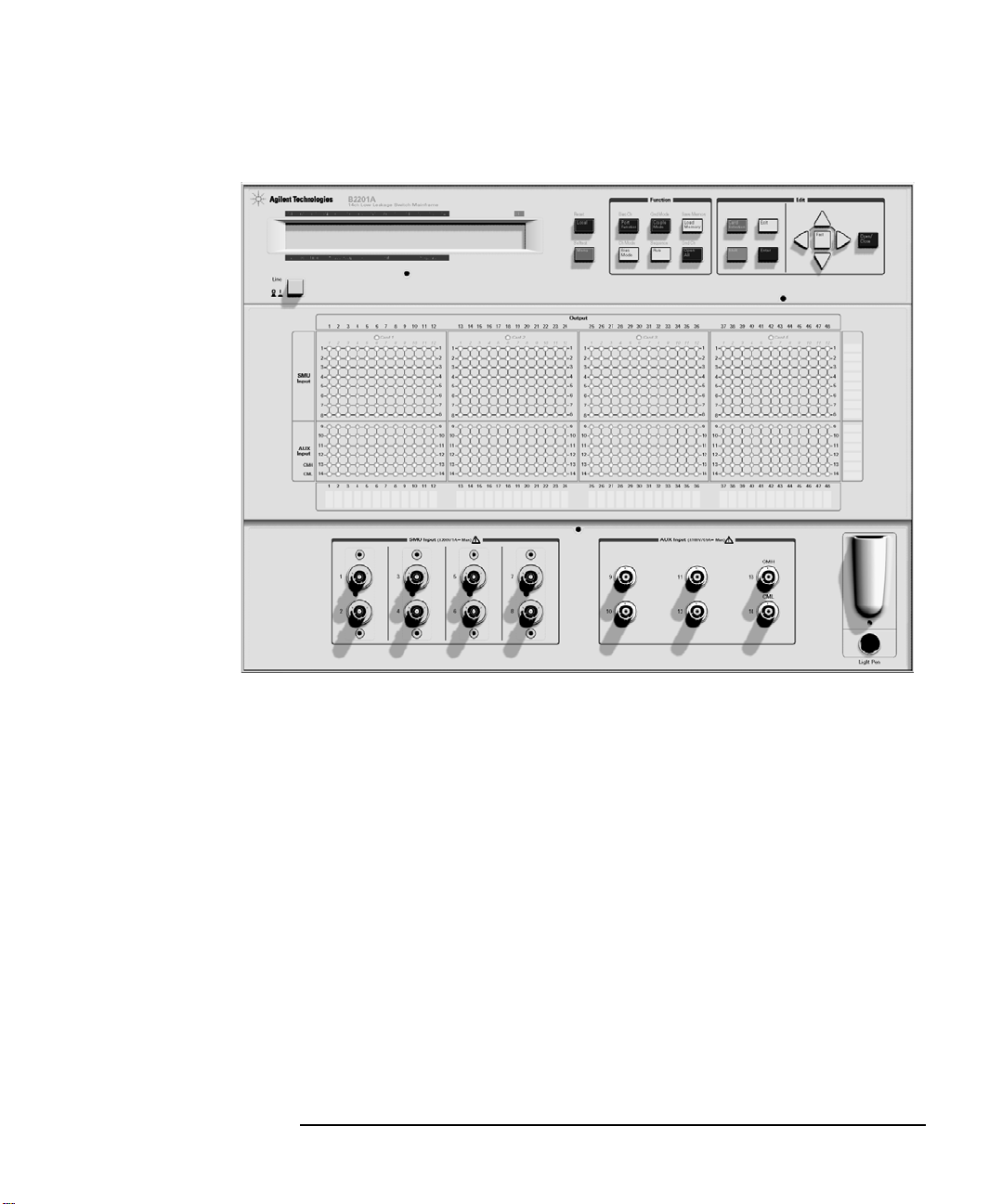
Figure 1-1 Front Panel View
Introduction
Front Panel
Agilent B2200 User’s Guide, Edition 4 1- 5
Page 24

Introduction
Rear Panel
Rear Panel
The Agilent B2200 series has four card slots for the switch modules, the GPIB
interface and so on.
• Card slots
For the Agilent B2200A mainframe, the Agilent B2210A cards are installed.
For the Agilent B2201A mainframe, the Agilent B2211A cards are installed.
Mixed configuration of the switch modules is not supported.
• GPIB interface
Use an Agilent 82357A USB/GPIB interface or Agilent 10833A/B/C/D GPIB
cable to connect to an external computer or equipment.
• Serial number
You need this serial number when using the Agilent Technologies telephone
assistance program.
• LINE input receptacle
AC power cable is connected to this receptacle.
1-6 Agilent B2200 User’s Guide, Edition 4
Page 25
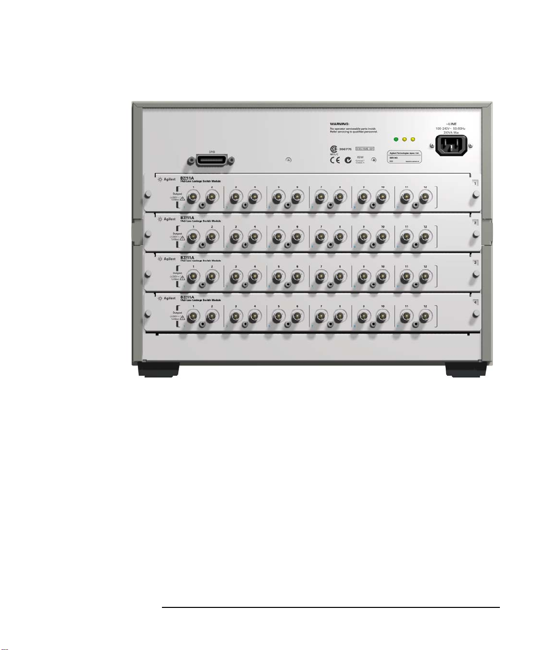
Figure 1-2 Rear Panel View
Introduction
Rear Panel
Agilent B2200 User’s Guide, Edition 4 1- 7
Page 26

Introduction
Switch Modules
Switch Modules
The Agilent B2200A and B2201A support the dedicated switch module, Agilent
B2210A and B2211A, respectively.
By installing the modules, the module inputs will be connected internally to the
front panel input connectors. And 12 output connectors will face the rear panel. The
type of the output connectors is the triaxial BNC. Up to six kelvin outputs are
available.
Image of the output terminals and the block diagram of the switch module are
shown in Figure 1-3 and Figure 1-4.
Figure 1-3 Switch Module Output Terminals
WARNING Do not touch the force and guard terminals of the output connectors while the
Agilent B2200 is turned on. Dangerous voltages up to the maximum input
voltage may be present at the output connectors.
NOTE Mixed configuration of the switch modules is not supported.
1-8 Agilent B2200 User’s Guide, Edition 4
Page 27
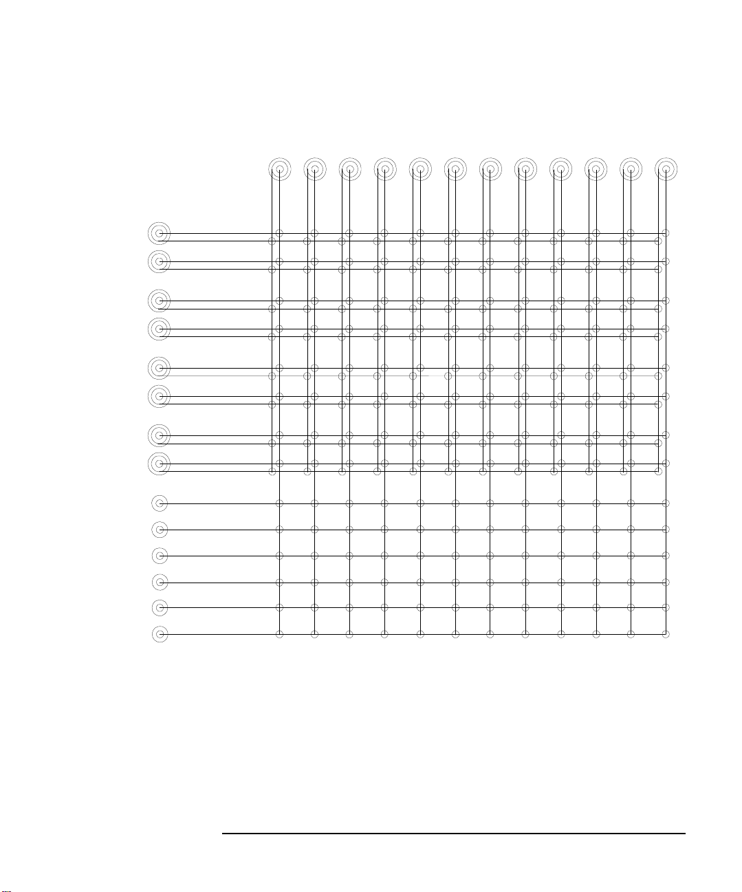
Figure 1-4 Switch Module Block Diagram
Output
Input
1
2
3
4
5
6
7
8
9
10
11
12
13 CMH
14 CML
1
2345
678
9
10 11 12
Introduction
Switch Modules
Agilent B2200 User’s Guide, Edition 4 1- 9
Page 28

Introduction
Specifications
Specifications
This section lists specifications and supplemental information for the Agilent B2200
series.
• “General Specifications”
• “Switch Modules”
• “Supplemental Characteristics for B2200A/B2210A”
• “Supplemental Characteristics for B2201A/B2211A”
The specifications are the performance standards or limits against which these units
have been tested. The supplemental characteristics is not warranted, but provides
useful information about the functions and performances of the instruments.
Specifications and supplemental characteristics are defined at the following
conditions.
Temperature: 23 °C ± 5 °C
Humidity: 5 % to 60 % relative humidity (R.H.)
1-10 Agilent B2200 User’s Guide, Edition 4
Page 29

General Specifications
Temperature range Operating: 5 °C to 35 °C
Storage: -20 °C to 70 °C
Humidity range Operating: 5 % to 70 % R.H., non-condensing
Storage:
For B2200A with B2210A: < 80 % at 35 °C, < 60 % at 65 °C, non-condensing
For B2201A with B2211A: < 80 % at 65 °C, non-condensing
Altitude Operating: 0 to 2,000 m (6,500 ft)
Storage: 0 to 15,240 m (50,000 ft)
Introduction
Specifications
Regulatory
compliance
Power
requirement
Number of slots 4 slots for 48 mm height switch module
Dimensions Mainframe: 430 mm W × 320 mm H × 600 mm D
Weight Mainframe: 14.0 kg
Number of ports I-V port: 8 triaxial ports (with guard)
EMC IEC 61326-1 / EN 61326-1
AS/NZS CISPR 11
Safety IEC 61010-1 / EN 61010-1
CAN/CSA-C22.2 No. 61010-1-04, NRTL/C
90 to 264 V (continuous), 47 to 63 Hz, 2 A/200 VA maximum
Module: 395 mm W × 48 mm H × 500 mm D
B2210A: 4.5 kg
B2211A: 3.5 kg
AUX port: 6 BNC ports (2 of CV port)
Output channel: 12 triaxial ports (with guard), maximum 48 ports
Agilent B2200 User’s Guide, Edition 4 1-11
Page 30

Introduction
Specifications
Switch Modules
Table 1-1 lists the specifications when the switch module is installed in the
mainframe. In the table, the conditions are as follows:
Conditions: 23 °C ± 5 °C, 5 % to 60 % R.H.
Table 1-1 Agilent B2210A/B2211A Switch Module Specifications
B2210A B2211A
Maximum current rating (A)
I-V port 1.0 1.0
AUX port 0.5 0.5
Maximum voltage rating (V)
I-V port, channel to common 200 200
I-V port, channel to other channel 300 300
AUX port, channel to common 100 100
AUX port, channel to other channel 100 100
Closed channel residual resistance (Ω)
I-V port 0.6 0.6
AUX port 1.5 1.5
Channel isolation resistance (Ω)
I-V port
AUX port
10
10
14
9
5 × 10
10
13
9
Agilent B2200A mainframe supports Agilent B2210A module.
Agilent B2201A mainframe supports Agilent B2211A module.
Mixed configuration of the switch modules is not supported.
1-12 Agilent B2200 User’s Guide, Edition 4
Page 31

Introduction
Specifications
Supplemental Characteristics for B2200A/B2210A
Offset current 1 10 fA, I-V port
IM noise (RMS)
Channel crosstalk capacitance < 1 pF per channel, I-V port
Offset voltage < 50 μV, I-V port
Settling time
Bandwidth (at -3dB) 30 MHz, AUX port
Guard capacitance
Additional C measurement error
2
0.6 fA, I-V port
< 3 pF per channel, AUX port
< 80 μV, AUX port
3
2.0 seconds at 50 fA
4
< 145 pF, I-V port
5
< ± 1 % + 0.2 pF, AUX port
1. The offset current when 0 V is applied to all I/O channels. This measurement
is made on a port, 5 seconds after switching a relay.
2. Measured by the Agilent 4156C with the integration time setting 100 PLC
when 0 V is applied to all other paths.
3. The time to settle to within 50 fA of the final value after 10 V is applied.
4. This is guard capacitance for an I/O channel for following conditions. Four
modules are installed in mainframe, and only one I/O channel is connected.
5. For the measurement less than 1000 pF at the frequency 1 kHz to 1 MHz,
using the Agilent 4284A with 3 m cable. After the compensation using the
capacitance compensation algorithm (a function of VXIplug&play driver).
Agilent B2200 User’s Guide, Edition 4 1-13
Page 32

Introduction
Specifications
Supplemental Characteristics for B2201A/B2211A
Offset current 1 100 fA, I-V port
IM noise (RMS)
Channel crosstalk capacitance < 0.5 pF per channel, I-V port
Offset voltage < 80 μV, I-V port
Settling time
Bandwidth (at -3dB) 30 MHz, AUX port
Guard capacitance
Additional C measurement error
2
5 fA, I-V port
< 3 pF per channel, AUX port
< 100 μV, AUX port
3
2.0 seconds at 300 fA
4
< 145 pF, I-V port
5
< ± 1 % + 0.2 pF, AUX port
1. The offset current when 0 V is applied to all I/O channels. This measurement
is made on a port, 60 seconds after switching a relay.
2. Measured by the Agilent 4156C with the integration time setting 100 PLC
when 0 V is applied to all other paths.
3. The time to settle to within 300 fA of the final value after 10 V is applied.
4. This is guard capacitance for an I/O channel for following conditions. Four
modules are installed in mainframe, and only one I/O channel is connected.
5. For the measurement less than 1000 pF at the frequency 1 kHz to 1 MHz,
using the Agilent 4284A with 3 m cable. After the compensation using the
capacitance compensation algorithm (a function of VXIplug&play driver).
1-14 Agilent B2200 User’s Guide, Edition 4
Page 33

Accessories and Options
Accessories and Options
Agilent B2200 is furnished with the following accessories.
• Power cable, 1 ea.
• Operation summary sheet, 1 ea.
• Software CD, 1 ea.
Stores the Agilent B2200 VXIplug&play driver.
• Moisture-proof and dehumidifying packing kit, 1 set
NOTE For the latest system requirements of the VXIplug&play driver, go to
www.agilent.com and type in B2200A in the Search field at the top of the page.
Available options and accessories are listed in Table 1-2.
Introduction
Agilent B2200 User’s Guide, Edition 4 1-15
Page 34

Introduction
Accessories and Options
Table 1-2 Options and Accessories
Model
Number
B2200A fA Leakage Switch Mainframe
B2201A 14ch Low Leakage Switch Mainframe
B2210A fA Leakage Switch Module (for B2200A)
B2211A 14ch Low Leakage Switch Module (for B2201A)
16443A Light pen
16493H GNDU cable (between 41501/4142 and 16495F/G)
16493J Interlock cable
16493K Kelvin triaxial cable
16493L GNDU cable (between E5260/E5270 and 16495F/G)
16493N GNDU cable for Kelvin connection
Option Item Description
B2200A-UK6 Commercial cal. certificate w/ test data
B2200A-ABA Manual set, English
B2200A-ABJ Manual set, Japanese
B2201A-UK6 Commercial cal. certificate w/ test data
B2201A-ABA Manual set, English
B2201A-ABJ Manual set, Japanese
16493H-001 1.5 m length
16493H-002 3 m length
(between E5260/E5270/4155/4156 and 16495F/G)
16493J-001 1.5 m length
16493J-002 3 m length
16493J-003 5 m length
(between B2200 inputs and E5260/E5270/4156/41501)
16493K-001 1.5 m length
16493K-002 3 m length
16493L-001 1.5 m length
16493L-002 3 m length
16493L-003 5 m length
(between B2200 inputs and E5260/E5270/41501/4142)
1-16 Agilent B2200 User’s Guide, Edition 4
Page 35

Introduction
Accessories and Options
Model
Number
16494A Triaxial cable
16494B Kelvin triaxial cable
16494C Kelvin triaxial cable
16494F CMU Input cable, 2 m
16495E Half size blank plate
16495F Half size connector plate with 12×triaxial, intlk, GNDU
16495G Full size connector plate with 24×triaxial, intlk, GNDU
Option Item Description
16494A-001 1.5 m length
16494A-002 3 m length
16494A-003 80 cm length
16494A-005 4 m length
(between B2200 inputs and 4142B, between B2210/B2211
outputs and 16495F/G)
16494B-001 1.5 m length
16494B-002 3 m length
16494B-003 80 cm length
(between B2210/B2211 outputs and B2220A)
16494C-001 1.5 m length
16494C-002 3 m length
16494C-005 4 m length
(between B2200 CMH/CML and 4-terminal pairs connectors)
16495F-001 Bulkhead feedthrough connectors (female to female)
16495F-002 Connectors to contacts for soldering
16495G-001 Bulkhead feedthrough connectors (female to female)
16495G-002 Connectors to contacts for soldering
Agilent B2200 User’s Guide, Edition 4 1-17
Page 36

Introduction
Accessories and Options
1-18 Agilent B2200 User’s Guide, Edition 4
Page 37

2 Installation
Page 38

Installation
This chapter describes requirements to install Agilent B2200 and the tasks for
installation, and is organized into the following three sections:
• “Requirements”
• “Inspection”
• “Installing the B2200”
• “Self-Test”
• “Output Connections”
• “Input Connections”
• “Measurement Cable Length”
• “Maintenance”
WARNING The maximum input voltage of the Agilent B2200 is ±200 V. And dangerous
voltages may be present at the output terminals. To prevent electric shock, you
must observe the following safety precautions when using the Agilent B2200.
• Use a three-conductor ac power cable to connect cabinet (if used) and the
Agilent B2200 to an electric ground (safety ground).
• If you need to touch the force and guard terminals of the output connector,
turn off the Agilent B2200 and discharge any capacitors whenever possible.
• Warn workers around the B2200 about dangerous conditions.
2-2 Agilent B2200 User’s Guide, Edition 4
Page 39

Installation
Requirements
Requirements
This section describes the following requirements for the Agilent B2200.
• “Power Requirements”
•“Power Cable”
• “Operating Environment”
• “Storage and Shipping Environment”
Power Requirements
CAUTION Before applying ac line power to the Agilent B2200, ensure that the correct power
cable is used.
The Agilent B2200 can operate from any single-phase ac power source supplying 90
to 264 V in the frequency range from 47 to 63 Hz. The maximum power
consumption is 2 A/200 VA.
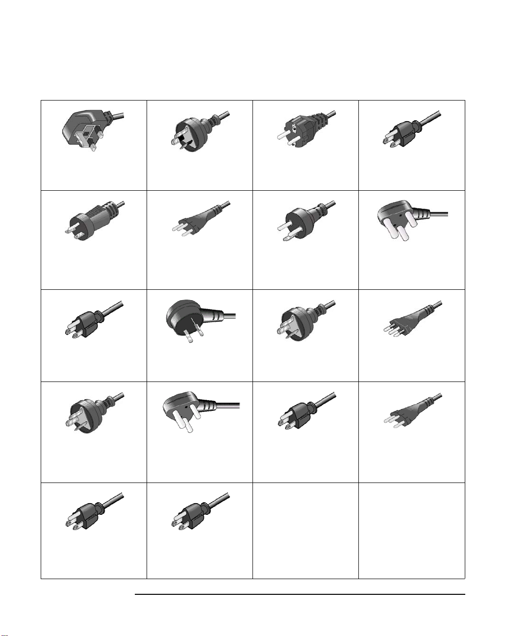
Power Cable
In accordance with international safety standards, this instrument is equipped with a
three-wire power cable. When connected to an appropriate ac power outlet, this
cable grounds the instrument frame. The type of power cable shipped with each
instrument depends on the country of destination. See the following table for the
part numbers of the power cables available.
If the plug on the cable does not fit the power outlet, or the cable is to be attached to
a terminal block, cut the cable at the plug end and re-wire it. This work should be
performed by a qualified electrician all local electrical codes being strictly observed.
The color coding used in the cable will depend on the cable supplied. If a new plug
is to be connected, it must meet local safety requirements and include the following
features:
• Adequate load-carrying capacity.
• Ground connection.
• Cable clamp.
Agilent B2200 User’s Guide, Edition 4 2- 3
Page 40
Installation
Requirements
• Plug: BS 1363/A,
250 V, 10 A
• PN: 8120-4420
• Plug: NEMA 6-15P,
250 V, 10 A
• PN: 8120-3996,
8120-0698
• Plug: JIS C 8303,
125 V, 12 A
• PN: 8121-0743
• Plug: GB 1002
figure 3 , 250 V, 10 A
• PN: 8120-8376
• Plug: AS 3112,
250 V, 10 A
• PN: 8120-4419
• Plug: SEV 1011,
250 V, 10 A
• PN: 8120-2104
• Plug: Israel SI 32,
250 V, 10 A
• PN: 8120-5182
• Plug: SANS 164-1,
250 V, 10 A
• PN: 8120-4211,
8121-0564
• Plug: CEE 7 sheet
VII, 250 V, 10 A
• PN: 8120-4519
• Plug: SR 107-2-D1,
250 V, 10 A
• PN: 8120-2956
• Plug: IRAM 207310A, 250 V, 10 A
• PN: 8120-6870
• Plug: TISI 166, 250 V,
10 A
• PN: 8121-1866
• Plug: NEMA 5-15P,
125 V, 10 A
• PN: 8120-6825
• Plug: IS 1293 and
IS 6538, 250 V, 10 A
• PN: 8120-4211
• Plug: CEI 23-16,
250 V, 10 A
• PN: 8120-6978
• Plug: NBR 14136,
250 V, 10 A
• PN: 8121-1809
• Plug: CNS 10917-2,
125 V, 10 A
• PN: 8120-6825,
8121-1635
• Plug: CS 0017:2003,
250 V, 10 A
• PN: 8120-8871,
8121-1638
2-4 Agilent B2200 User’s Guide, Edition 4
Page 41

Installation
Requirements
WARNING For protection from electrical shock, the power cable ground must not be
defeated.
Operating Environment
The Agilent B2200 must be operated within the following environmental
conditions:
• Temperature: 5 °C to 35 °C
• Humidity: 5 % to 70 % R.H., non-condensing
• Altitude: 0 m to 2,000 m
Storage and Shipping Environment
The Agilent B2200 should be stored or shipped in environments within the
following limits:
• Temperature: -20 °C to 70 °C
•Humidity:
B2200A/B2210A:
< 80 % R.H. (at 35 °C), < 60 % R.H. (at 65 °C), non-condensing
B2201A/B2211A:
< 80 % R.H. (at 65 °C), non-condensing
• Altitude: 0 m to 15,240 m
CAUTION When storing the Agilent B2200
Protect the Agilent B2200 from temperature extremes to prevent condensation from
forming inside the Agilent B2200. If condensation occurs, the Agilent B2200 may
damage or may not satisfy the specifications. If the Agilent B2200 was placed at the
high temperature and high humidity environment long time, the Agilent B2200 may
degrade its performance.
NOTE When shipping the Agilent B2200
The Agilent B2200 must be packed in the certain packing materials for protection
from damage when it is shipped. Cover the Agilent B2200 by using the
moisture-proof and dehumidifying packing material (furnished), and pack it by
using packing materials such as carton box and cushioning materials.
Agilent B2200 User’s Guide, Edition 4 2- 5
Page 42

Installation
Inspection
Inspection
CAUTION Before Opening Packing Materials
The Agilent B2200 contains the condensation sensitive electronic parts. The
condensation will have a negative impact on the Agilent B2200 to operate normally.
Do not open the packing materials, and leave the Agilent B2200 to acclimate it to
the installation environment (temperature and humidity). If it is opened without
enough acclimation, the Agilent B2200 may damage.
When you open the box that contains the Agilent B2200, check the following:
1. Before unpacking any components, inspect all boxes for any signs of damage
that might have occurred during shipment such as:
•Dents
• Scratches
•Cuts
• Water marks
2. When you open the boxes that contain the Agilent B2200, check the components
against the contents lists that are attached to the boxes.
If anything is wrong, notify your local Agilent Technologies sales office.
2-6 Agilent B2200 User’s Guide, Edition 4
Page 43

Installation
Installing the B2200
Installing the B2200
This section describes how to install the Agilent B2200.
1. See “Requirements” on page 2-3, and determine the installation location.
2. Unpack the Agilent B2200 and place it at the installation site.
3. Plug the power cable into the Line input receptacle at the rear panel.
4. Plug the power cable into the power receptacle.
5. Perform the self-test. See “Self-Test” on page 2-10.
6. If you control the Agilent B2200 by using an external computer:
Set the GPIB address. See “To Set the GPIB Address” on page 2-8 and “To
Connect the GPIB Cable” on page 2-8.
7. If you have to add or replace the switch module:
Turn the Agilent B2200 off, remove the power cable, and install the switch
module. See “To Install the Switch Module” on page 2-9 and “To Install the
Blank Panel” on page 2-9.
NOTE Plug-in module is shipped from the factory after the specifications are confirmed.
Agilent can guarantee that the modules will function and that the module
performance is designed to meet its specifications. However, if you have any
trouble, contact your nearest Agilent Technologies service center.
If you require that the modules be guaranteed to their specifications (for ISO
compliance, etc.), then you must perform a calibration on the instrument (modules
and mainframe together). For calibration, contact your nearest Agilent Technologies
service center.
Agilent B2200 User’s Guide, Edition 4 2- 7
Page 44

Installation
Installing the B2200
To Set the GPIB Address
Every device on the GPIB bus must have a unique address. If you need to change
the GPIB address, turn the Agilent B2200 on and perform the following procedure.
The new GPIB address is recognized only at power on. The Agilent B2200 leaves
the factory with the GPIB address set to 22.
1. Press the
2. Move the cursor to CONFIG, then press the
3. Move the cursor to ADDRESS, then press the
Menu key.
Enter key.
Enter key. The following message
will appear on the LCD. XX will be 0 to 30.
GPIB Address = XX
4. Press the arrow key (up or down) to specify the desired GPIB address, then press
the
Enter key.
5. Press the
Enter key twice.
6. Turn the Agilent B2200 off, and then turn it on again.
To Connect the GPIB Cable
To connect the instrument with a computer or peripheral device via GPIB (IEEE
Std. 488), connect an GPIB cable between the GPIB connector on the instrument
rear panel and the GPIB connector on the peripheral device.
Including the controller, a total of 15 GPIB interfaces can be connected on the same
GPIB bus. The following are rules for connecting GPIB interfaces:
• If total number of interfaces ≤ 10:
Max. total cable length = number of interfaces × 2 m.
• If total number of interfaces > 10:
Max. total cable length = 20 m.
• Maximum cable length between interfaces is 4 m.
• Star connection and cascade connection are allowed. Loop connection is not
allowed.
2-8 Agilent B2200 User’s Guide, Edition 4
Page 45

Installation
Installing the B2200
To Install the Switch Module
WARNING To prevent electrical shock, turn off the mainframe and remove the power
cable before starting the instruction.
CAUTION Be careful about the module pins used for internal connection to the Agilent B2200.
The pins can be damaged easily.
Use clean handling and anti-static procedures when removing, configuring, and
installing the switch modules. The modules contain components that can be
damaged by static electricity.
The following procedure explains the module installation and removal.
1. Turn off the Agilent B2200, then wait at least 10 seconds before you remove or
install a module.
2. Loosen the screws on both the left and right edges of a blank panel or a module
attached to the slot you want to install a new module.
3. Remove the blank panel or the module.
4. Align the new module with the left and right slot guide rails. Then the
component side should be facing up.
5. Push the module into the slot until you feel it seat firmly into the connector at the
back of the slot.
6. Screw in the screws on the left and right edges of the module.
7. Execute the self-test and the relay test. See “Self-Test” on page 2-10.
To Install the Blank Panel
CAUTION To prevent thermal damage to the module, be sure that blank panels are installed in
all unused slots.
If the blank panel is not installed to cover an unused slot, install the blank panel as
follows:
1. Align the blank panel over the unused slot.
2. Screw in the screws on the left and right edges of the blank panel.
Agilent B2200 User’s Guide, Edition 4 2- 9
Page 46

Installation
Self-Test
Self-Test
NOTE To confirm the specifications
The self-test and diagnostics checks the operation of the mainframe and the
modules. However they cannot confirm if the Agilent B2200 satisfies its
specifications.
For verifying the specifications, contact your nearest Agilent Technologies Service
Center. Trained service personnel will perform calibration (performance
verification).
It is recommended to perform calibration once a year at least.
The following procedure performs the self-test and diagnostics.
1. Turn on the Agilent B2200.
The controller test will be performed. If the Agilent B2200 fails the test, contact
your nearest Agilent Technologies Service Center.
2. Press the
Shift key and the Menu key in this order. Self-test menu will appear on
the LCD.
SELF_TEST Controller test
RELAY_TEST Relay test
KEY Front panel interface test
BEEPER Beeper test
LED LED matrix test
PEN Light pen test
GPIB GPIB test
3. Move the cursor to the test item to perform, then press
4. To start the test, move the cursor to EXECUTE, then press
To display the previous test result, move the cursor to RESULT, then press
Enter key.
Enter key.
Enter
key.
For the details of each test, see “Selftest Menu” on page 3-34.
2-10 Agilent B2200 User’s Guide, Edition 4
Page 47

Installation
B
A
SMU
Input
AUX
B
A
Force or Sense
Signal line
Guard
Ground
Ground
Output Connections
Output Connections
This section describes how to connect the Agilent B2200 outputs to prober,
connector plate, test fixture, and so on (DUT interface).
• “Output Connectors”
• “Connector Plates”
• “To Make Connections to DUT Interface”
• “To Make Interlock Circuit”
• “To Mount Connectors”
NOTE Output Connections
If you do not use the connector plate for the connection between the output and the
DUT interface, see “To Mount Connectors” on page 2-18.
WARNING Turn off the Agilent B2200 and all instruments connected. And do not turn
them on until the connection described in this section is completed. If you
ignore this warning, you may be exposed to dangerous voltage.
Figure 2-1 Output Connector and Output Signal
Output Connectors
The Agilent B2200 output connectors are the triaxial BNC connector. The input
signal (SMU input or AUX input) appears at the output connector as shown in
Figure 2-1 when input-output switching path is made.
Agilent B2200 User’s Guide, Edition 4 2-11
Page 48

Installation
Output Connections
Connector Plates
Connector plates (Table 2-1) are used for the connection between the Agilent B2200
outputs and the DUT interface (prober and so on). To connect to the connector plate,
use the cable shown in Table 2-2.
Table 2-1 Connector Plate
Agilent Model No. Description
16495F Half size connector plate
16495F-001 has 12 triaxial through connectors (female to female), an Intlk
connector, and a GNDU connector (triaxial through, female to female). The back
of the Intlk connector is designed for soldering.
16495F-002 has 12 triaxial connectors, an Intlk connector, and a GNDU
connector. The back of each connector is designed for soldering.
16495G Full size connector plate
16495G-001 has 24 triaxial through connectors (female to female), an Intlk
connector, and a GNDU connector (triaxial through, female to female). The back
of the Intlk connector is designed for soldering.
16495G-002 has 24 triaxial connectors, an Intlk connector, and a GNDU
connector. The back of each connector is designed for soldering.
16495E Blank plate
This plate is used to cover openings when you made too big openings for
mounting the connector plate. You will use this plate to cover openings if you
mount the half size connector plate in openings made for the full size connector
plate.
Table 2-2 Output Cable
Agilent Model No. Description
16494A Triaxial cable (for non-Kelvin connection)
16494B Kelvin Triaxial cable (for Kelvin connection)
NOTE Installing Connector Plate
To install the connector plate, refer to Agilent 16495 Installation Guide.
2-12 Agilent B2200 User’s Guide, Edition 4
Page 49
Installation
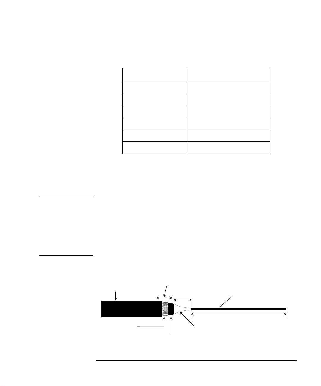
Insulator (black)
Outer conductor
(for Guard signal)
Insulator (clear)
Conductive layer (black)
Center conductor
(for Force/Sense signal)
approx. 10 to 15 mm
min 2 mm
Cover here using sleeve
Output Connections
For Kelvin connection, use Kelvin triaxial cable listed in Table 2-2. To make a
Kelvin output port (1, 3, 5, 7, 9 and 11), couple two E5252A output ports as follows:
Kelvin Output Port Output Port Number
1 1 (Force) and 2 (Sense)
3 3 (Force) and 4 (Sense)
5 5 (Force) and 6 (Sense)
7 7 (Force) and 8 (Sense)
9 9 (Force) and 10 (Sense)
11 11 (Force) and 12 (Sense)
To Make Connections to DUT Interface
This section describes for the connections between the DUT interface and the
connectors connected to the Agilent B2200 output cables. See Table 2-3.
NOTE Low-Noise Coaxial Cable
For the extended measurement paths over the connector plate, use low-noise coaxial
cable (Agilent part number 8121-1191). This cable can maximize the guard effects
and minimize the impression of the external noise.
Figure 2-2 shows the cutting example of this cable. Key point is the isolation
between the conductive layer and the center conductor. So, cut and trim the end of
the cable as shown in this figure by using a cutter and so on.
Figure 2-2 Coaxial Cable Cutting Example
Agilent B2200 User’s Guide, Edition 4 2-13
Page 50
Installation
to
DUT
Coaxial cable
Triaxial
connector
Insulator
Plate
Guard
Sense
Common
Guard
Force
Common
to
DUT
Coaxial cable
Triaxial
connector
Insulator
Plate
Guard
Sense
Common
Wi re
Guard
Force
Common
Output Connections
Table 2-3 Connection to the DUT Interface
Kelvin connections non-Kelvin connections
This connection is available only for the
Kelvin connectors.
This connection can cancel effects of cable
resistance by connect sense line and force line
as close as possible to DUT terminal.
Following connection is for the Kelvin
connectors. For the triaxial connectors,
ignore SENSE terminal, and make
connection only for FORCE terminal.
Measurement data will include residual
resistance from the connection cable.
CAUTION Never connect the guard terminal to any output, including circuit common, chassis
ground, or the guard terminal of any other unit. Doing so may result in an
emergency condition.
For highly accurate current forcing and measurements while minimizing leakage,
surround all force and sense lines from SMU by a guard as far as possible, and make
cables stable by taping.
For reducing capacitance measurement error, tape the cables to any grounded
materials such as shielding box. If you use probe card, grounding the probe card also
reduces capacitance measurement error.
2-14 Agilent B2200 User’s Guide, Edition 4
Page 51
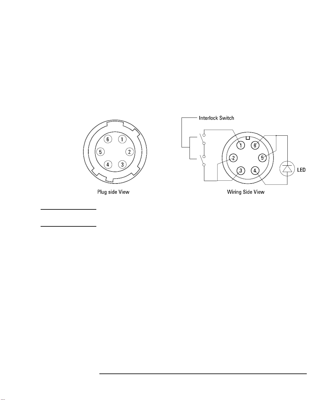
To Make Interlock Circuit
The interlock circuit is to prevent electric shock when touching measurement
terminals. You must install an interlock circuit on shielding box to prevent
dangerous voltages when door of the shielding box is open.
Figure 2-3 shows the pin assignments of the interlock connector.
Figure 2-3 Interlock Connector Pin Assignments
Installation
Output Connections
WARNING Dangerous voltages of up to the maximum voltage of SMUs may be present at
force, guard, and sense terminals when the interlock terminals are shorted.
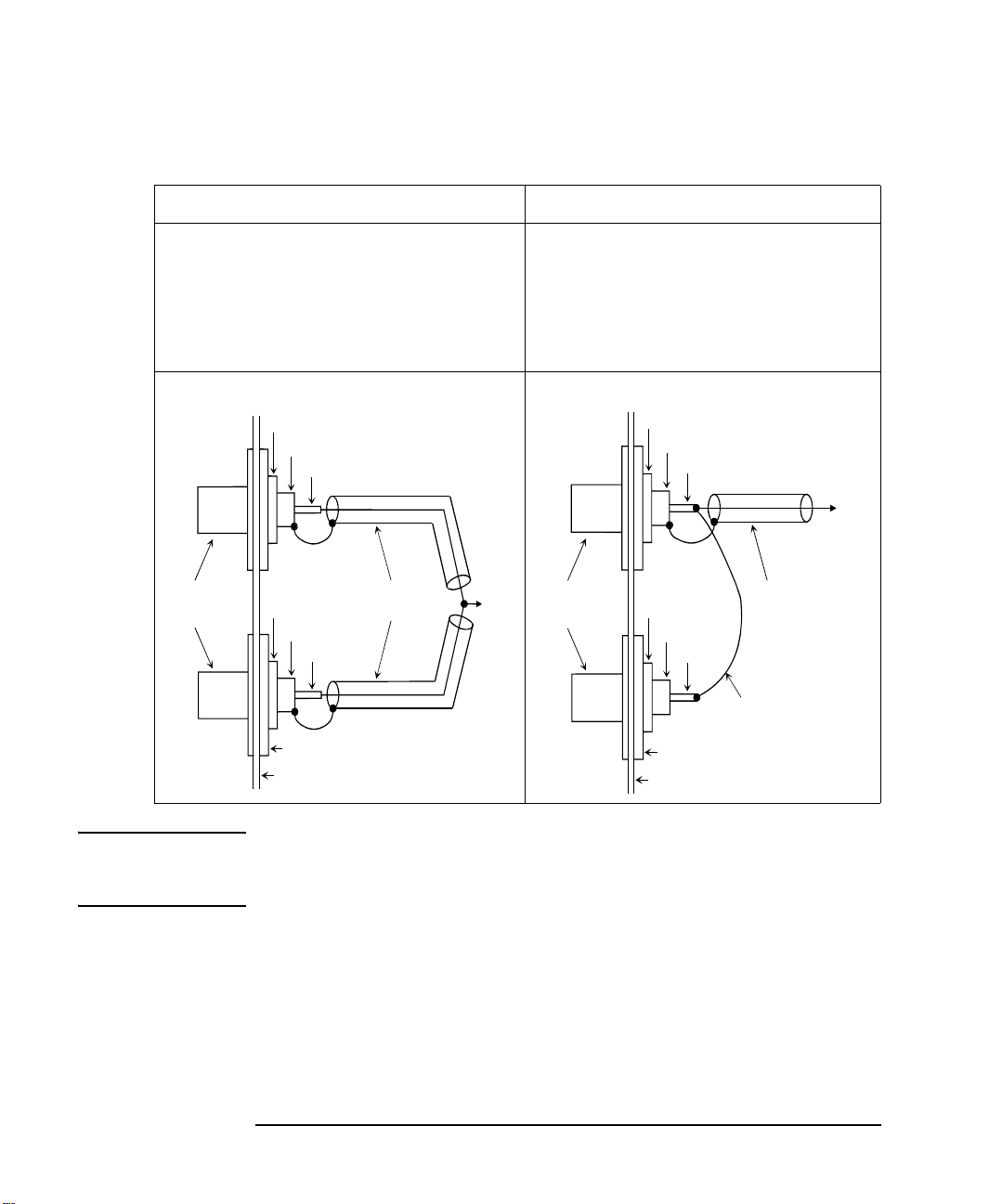
To Install Interlock Circuit
Install the interlock circuit as follows.
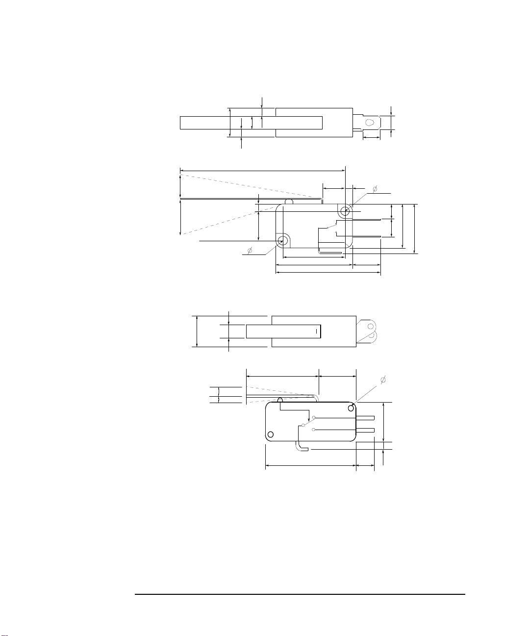
1. Mount two mechanical switches on your shielding box, so that the switches
close when the door of the shielding box is closed, and open when the door is
opened. For the recommended parts and the dimensions of the switch, see Figure
2-4 and Figure 2-5.
2. Use wire to connect the two switches in series between pin number 1 and 2 (or
3) of the interlock connector. See Figure 2-3.
For example, Agilent 4155/4156 is connected to the interlock circuit, it cannot force
more than ±40 V when the door is open. When door is closed, it can force more than
±40 V.
Agilent B2200 User’s Guide, Edition 4 2-15
Page 52
Installation
3.1
Switch on
59.4
8.1
10
UGI01011,85x60
Units: mm
NC
NO
COM
6.35
22.2
27.8
37.8
2.8
6.5
5.5
15.9
18.8
4.75
10.3
4.3
2.8
2.8
Switch off
Max 9
15.2
10.3
2.8
3.1
3.1
Switch off
Switch on
27.5
10.9
15.9
3.4
27.8 6.8
10.2 4.3
3.2
2.0
UGI01012,85x60
Units: mm
Output Connections
Figure 2-4 Dimensions of Interlock Switch (Agilent part number 3101-0302)
Figure 2-5 Dimensions of Interlock Switch (Agilent part number 3101-3241)
To Install LED Circuit
To install LED circuit on your shielding box, do following:
1. Mount LED on your shielding box. For the recommended parts and the
dimensions of the LED, see Figure 2-6.
2. Use wire to connect the LED between pin 4 and pin 5 (or 6) of the interlock
connector. See Figure 2-3.
2-16 Agilent B2200 User’s Guide, Edition 4
Page 53

The 4155/4156 semiconductor parameter analyzer's Intlk connector provides the
6
10
11
5
5.6
5
Cathode(-)
Anode(+)
Units: mm
interlock signal and a LED drive signal. If a LED is connected between pin 4 and
pin 5 (or 6) of the interlock connector, the LED lights to indicate high voltage output
when more than ±40 V is forced from an SMU in the 4155/4156.
Figure 2-6 Dimensions of LED (Agilent part number 1450-0641)
To Connect Interlock Circuit to Instrument
Installation
Output Connections
Before beginning the measurement, connect the interlock circuit to the instrument’s
interlock connector as follows.
• For the instruments which has a BNC-Type interlock connector:
1. Get the following parts.
• Agilent 16493J Interlock cable, 1 ea.
• Agilent 16435A Interlock cable adapter, 1 ea.
2. Connect the 16493J interlock cable between the interlock circuit and the
16435A adapter.
3. Connect the BNC cable (furnished with the adapter) between the adapter and
the instrument’s interlock connector.
• For Agilent 4155/4156/E5260/E5270:
Connect the 16493J interlock cable between the interlock circuit and the
instrument’s interlock connector. You can connect it directly without using any
adapter.
Agilent B2200 User’s Guide, Edition 4 2-17
Page 54

Installation
Output Connections
NOTE To Check Interlock Circuit
If you use the 4155/4156, you can easily check the interlock circuit as follows:
1. Connect the Intlk connector of the 4155/4156 to your interlock circuit.
2. Press
3. In the CALIB/DIAG field, select DIAG secondary softkey.
4. In the CATEGORY field, select I/O PERIPH secondary softkey.
5. Move pointer to the 403 (INT.) Interlock LED field.
6. Select EXECUTE secondary softkey.
7. Confirm the following:
To stop the interlock test, select STOP secondary softkey.
System front-panel key, then select CALIB/DIAG primary softkey to
display the SYSTEM: SELF-CALIBRATION/DIAGNOSTICS page.
• LED turns on within 1 sec from when interlock circuit is shorted.
• LED turns off within 1 sec from when interlock circuit is open.
To Mount Connectors
This section provides the information needed to mount connectors for the Agilent
B2200 output cable connections on the shielding panel. See this section if you do
not use the connector plate.
1. Get the appropriate parts for your situation. Refer to Table 2-4.
2. Make holes and mount the connectors. Refer to Table 2-5.
For kelvin connections, use the Kelvin cables. The Kelvin cable requires the
kelvin triaxial connector which has two connector holes and three screw holes.
3. Make an interlock circuit as shown in “To Make Interlock Circuit” on page 2-15.
4. Make cable connections to the DUT interface. Refer to “To Make Connections
to DUT Interface” on page 2-13.
2-18 Agilent B2200 User’s Guide, Edition 4
Page 55
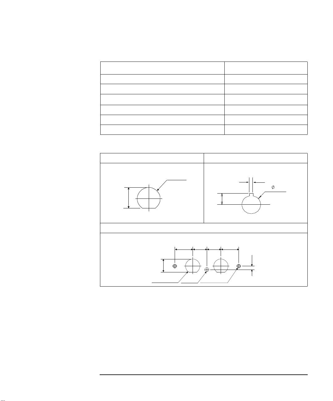
Table 2-4 Recommended Parts
∅11.3
10.3
1.8
8.2
5
.
1
2 − ∅11.3 ∅3.2 2 − M3 x 0.5
14 11 11 14
2.8
10.3
Description Agilent Part No.
Interlock Connector (6 pin, female) 1252-1419
Switch 3101-0302 or 3101-3241
LED (V
@ 2.1 V @ IF = 10 mA) 1450-0641
F
Wire (24 AWG, 600 V, 150 °C) 8150-5680
Triaxial Connector (female) 1250-2457
Low Noise Coaxial Cable 8121-1191
Table 2-5 Dimensions of Connector Holes
Triaxial Connector (in mm) Interlock Connector (in mm)
Installation
Output Connections
Kelvin Triaxial Connector (in mm)
Agilent B2200 User’s Guide, Edition 4 2-19
Page 56

Installation
Input Connections
Input Connections
This section explains how to connect instruments to the Agilent B2200.
WARNING Turn off all instruments that will be connected to the Agilent B2200. And do
not turn them on until the connection described in this section is completed. If
you ignore this warning, you may be exposed to dangerous voltage.
The Agilent B2200 input connector has eight SMU input connectors and six AUX
input connectors. Table 2-6 shows cables used to connect the instrument for typical
applications using the Agilent B2200.
You can make the Kelvin connections when using the E5260/E5270/4142/4156
SMU or 41501 HPSMU. Then use cables as follows:
• Agilent 16493K Kelvin triaxial cable for Agilent E5260/E5270/4156/41501
• Agilent 16494B Kelvin triaxial cable for Agilent 4142B
To connect the Kelvin triaxial cable to the Agilent B2200 input, use pairs (couple
ports) of the SMU input connectors (1&2, 3&4, 5&6, or 7&8). The input signal for
each Kelvin input is as follows:
• Odd input port number: Force
• Even input port number: Sense
Ground Unit (GNDU) can sink over 1 A. For the measurement over 1 A, connect the
GNDU to the connector plate directly by using the Agilent 16493H GNDU cable.
If you never perform the measurement over 1 A, you can connect the GNDU to the
Agilent B2200 inputs. Then use the Agilent 16493N GNDU cable. This cable
requires the Kelvin connection.
CAUTION Make sure current to the GNDU is less than 1 A if you connect GNDU to the
Agilent B2200 inputs. The maximum input current of the Agilent B2200 is 1A.
2-20 Agilent B2200 User’s Guide, Edition 4
Page 57

Table 2-6 B2200 Input Connections
Installation
Input Connections
Application
DC
Measurement
Instrument
Agilent
Model No.
4155 MPSMU SMU1 to 8 16494A triaxial cable
4156 HRSMU SMU1 to 8 16493K Kelvin triaxial cable or
41501 HPSMU SMU1 to 8 16493K Kelvin triaxial cable or
4142B SMU SMU1 to 8 16494B Kelvin triaxial cable or
Output
Connector
VSU AUX1 to 6 BNC cable
VMU AUX1 to 6 BNC cable
Intlk − 16493J interlock cable
VSU AUX1 to 6 BNC cable
VMU AUX1 to 6 BNC cable
Intlk − 16493J interlock cable
MPSMU SMU1 to 8 16494A triaxial cable
PGU AUX1 to 6 BNC cable
GNDU SMU1 to 8 16493N GNDU Kelvin cable
VSU AUX1 to 6 BNC cable
VMU AUX1 to 6 BNC cable
GNDU SMU1 to 8 16493HN GNDU Kelvin cable
Intlk − 16435A interlock cable adapter
B2200
Input
Connector
(for direct connection to connector plate)
16494A triaxial cable
(for direct connection to connector plate)
16494A triaxial cable
− 16493H GNDU cable
(for direct connection to connector plate)
16494A triaxial cable
− 16493H GNDU cable
(for direct connection to connector plate)
and 16493J interlock cable
(for direct connection to Connector Plate)
Cable Required
Agilent B2200 User’s Guide, Edition 4 2-21
Page 58

Installation
Input Connections
Application
DC
Measurement
C
Measurement
Pulse Input Pulse
Bias Input Power
Agilent
Model No.
E5260/
E5270
C Meter High, Low CMH/CML 16494F CMU cable for 4 terminal pairs
Generator
Supply
Instrument
Output
Connector
SMU SMU1 to 8 16493K Kelvin triaxial cable or
GNDU SMU1 to 8 16493N GNDU Kelvin cable
Interlock − 16493J interlock cable
Output AUX1 to 6 BNC cable
Output AUX1 to 6 BNC cable
In the table above,
• CMH/CML connectors are a pair of the AUX inputs.
• The Agilent B2200 does not have the interlock connector. Connect directly from
instrument to the connector plate which has an interlock connector.
B2200
Input
Connector
16494A triaxial cable
− 16493H GNDU cable
(for direct connection to connector plate)
(for direct connection to connector plate)
Cable Required
• The Agilent 41422A/41423A (HCU/HVU) of the Agilent 4142B cannot be used
with the Agilent B2200.
• To connect instrument output that uses banana plug to the AUX connector, use
the dual banana plug to BNC adapter (Agilent part number 1251-2277).
2-22 Agilent B2200 User’s Guide, Edition 4
Page 59

Installation
Measurement Cable Length
Measurement Cable Length
This section describes how to calculate the total guard capacitance when using an
SMU (source monitor unit). When using an SMU, the length of measurement cables
is limited by the guard capacitance of the cables. The guard capacitance means the
capacitance between the signal line (Force or Sense) and the Guard line.
Table 2-7 lists the guard capacitance for each element of the Agilent B2200’s
measurement environment.
When using the 4155/4156/4142B/E5260/E5270, the maximum limit of the guard
capacitance is approximately 900 pF. So, you add the following and total must be
less than 900 pF:
• Guard capacitance of cable from SMU to B2200 inputs.
• Guard capacitance of mainframe and modules.
• Guard capacitance of cable from B2200 outputs.
• Guard capacitance of cable from connector plate to DUT.
• Other capacitances, such as for probe card.
The following is an example to calculate the guard capacitance of a measurement
environment:
Installed Plug-in cards: Four B2210As (145 pF + 8 pF × 3)
Input Cable: 16494A-003 (75 pF)
Output Cable: 16494A-001 (130 pF)
Cable from Connector
Plate to DUT: 8121-1191, 1 m (130 pF)
Probe Card: Guard Capacitance approximately 10 pF (example)
In this environment, the total guard capacitance (Cg-total) is as follows.
Cg-total = 145+(8×3)+75+130+130+10 pF = 514 pF < 900 pF
Even if you use other instruments, you can use the table for reference about the
measurement cable length and capacitance.
Agilent B2200 User’s Guide, Edition 4 2-23
Page 60

Installation
Measurement Cable Length
Table 2-7 Guard Capacitances of B2200 Measurement Environment (Typical)
Connection Agilent Model/Part No.
from SMU to B2200
inputs
mainframe and
modules
from B2200 outputs
to connector plate or
probe card interface
16494A-003 (for non-Kelvin) 80 cm 75 pF
16494A-001 (for non-Kelvin) 1.5 m 130 pF
16494B-003 (for Kelvin, 4142B) 80 cm 90 pF
16493K-001 (for Kelvin) 1.5 m 150 pF
B2210A (only 1 card is installed) − 145 pF
B2210A (more 1 card) − 8 pF/extra card
B2211A (only 1 card is installed) − 145 pF
B2211A (more 1 card) − 8 pF/extra card
16494A-001 (for non-Kelvin) 1.5 m 130 pF
16494A-002 (for non-Kelvin) 3 m 240 pF
16494A-003 (for non-Kelvin) 4 m 340 pF
16494B/C-001 (for Kelvin) 1.5 m 140 pF
16494B/C-002 (for Kelvin) 3 m 260 pF
Cable
Length
Guard
Capacitance
16494C-003 (for Kelvin) 4 m 340 pF
from connector
plate to DUT
probe card interface B2220A − 70 pF
Agilent Part No. 8121-1191 X m 130 pF per m
2-24 Agilent B2200 User’s Guide, Edition 4
Page 61

Installation
Maintenance
Maintenance
Maintenance should be performed periodically to keep the B2200 in good condition.
Calibration
Calibration must be performed periodically so that the instruments satisfy the
specifications, and keep a good condition. It is recommended to perform a
calibration once a year at least. For calibration, contact your nearest Agilent
Technologies Service Center. Trained service personnel will perform calibration
(performance verification).
Cleaning
Before performing cleaning, turn off the instrument, and disconnect power cable
from the rear panel. Use a dry cloth to clean the external case parts.
To prevent electrical shock, do not perform cleaning when the instrument is turned
on, and do not use a wet cloth.
Agilent B2200 User’s Guide, Edition 4 2-25
Page 62

Installation
Maintenance
2-26 Agilent B2200 User’s Guide, Edition 4
Page 63

3 Front Panel Operation
Page 64

Front Panel Operation
This chapter explains the front panel operation and the switch control functions of
the Agilent B2200, also provides the reference information of the front panel keys
and display.
• “Operation”
• “Switch Control Functions”
• “Display Functions”
• “Front Panel Keys”
• “Setup Menus”
3-2 Agilent B2200 User’s Guide, Edition 4
Page 65

Operation
This section describes operations of the Agilent B2200.
• “To Initialize Agilent B2200”
• “To Enable Light Pen”
• “To Change Channel Configuration Mode”
• “To Change Connection Rule”
• “To Change Connection Sequence”
• “To Control Switch Condition”
• “To Open All Switches”
• “To Save/Load Setup Data”
• “To Use Bias Mode”
• “To Use Ground Mode”
Front Panel Operation
Operation
• “To Use Couple Mode”
• “To Display Firmware Revision”
• “To Display Module Information”
• “To Read Error Message”
• “To Set Beeper”
• “To Set GPIB Address”
• “To Set Remote Display Mode”
• “To Return to Local Mode”
NOTE About moving cursor, selecting value, and changing display
Use the right/left arrow key to move the cursor to the desired function name. Use the
up/down arrow key to select the value for the setup item.
The
Enter key makes the setup effective, and returns the display to the previous
menu or display.
The
Exit key returns the display to the previous menu or display without making the
setup effective.
Agilent B2200 User’s Guide, Edition 4 3- 3
Page 66

Front Panel Operation
Operation
To Initialize Agilent B2200
1. Press the Shift key and the Local key. Then the LCD will display NO.
2. Press the arrow key to displays YES, then press the
Agilent B2200, or press the
To Enable Light Pen
Turn the Agilent B2200 off, and connect the light pen to the Light Pen connector at
the right down corner of the front panel. After that, perform the following procedure
to enable the light pen.
1. Press the
2. Press the arrow key to move the cursor to PEN, then press the
3. Press the arrow key to display ENABLE, then press the
light pen, or press the
NOTE Light Pen
You can control the Agilent B2200 functions and the switch connections by using
the front panel keys. And the Agilent B2200 allows you to use the Agilent 16443A
Light Pen to control the switch connections.
Pointing a LED on the LED matrix by using the light pen controls the setting of the
switch specified by the LED.
To Change Channel Configuration Mode
Enter key to initialize the
Exit key to cancel initialization.
Menu key. The setup menu will be displayed on the LCD.
Enter key.
Enter key to enable the
Exit key to cancel changing the setup.
1. Press the Shift key and the Bias Mode key. The LCD displays the present setting
(AUTO or NORMAL).
2. Press the arrow key to select the mode, then press the
Enter key. The LCD
displays NO.
3. Press the arrow key to display YES, then press the
Enter key. Or press the Exit
key to cancel this operation.
Changing the channel configuration mode resets the Agilent B2200.
3-4 Agilent B2200 User’s Guide, Edition 4
Page 67

Front Panel Operation
Operation
To Change Connection Rule
1. Press the Rule key. The LCD displays the present setting (FREE or SINGLE).
2. Press the arrow key to select the connection rule, then press the
press the
Exit key to cancel this operation.
Enter key. Or
To Change Connection Sequence
1. Press the Shift key and the Rule key. The LCD displays the present setting
(Break_Before_Make, Make_Before_Break, or No_Sequence).
2. Press the arrow key to select the connection sequence, then press the
Or press the
Exit key to cancel this operation.
Enter key.
To Control Switch Condition
If you use the light pen, you do not need the following instruction to control the
switch condition.
1. If you are NOT watching the orange-blink-LED on the LED matrix, press the
Open/Close key. The blink-LED will appear.
2. Press the arrow keys to move the blink-point.
3. Press the
The green-LEDs indicate the switches that are closed now.
4. Repeat 2 and 3 until the switch setup is completed.
Blinking of LED will be stopped by pressing the front panel key other than the
Open/Close, Fast, or arrow keys.
Open/Close key to open/close the switch specified by the blink-LED.
NOTE When Kelvin cables are connected to Outputs
For the Kelvin outputs, the input-output paths must be controlled as shown below.
• For the input couple port:
Control the switches to connect the input couple port to the Kelvin output.
• For the single input port:
Control the switches to connect the input port to two ports of the Kelvin output.
If you do not comply with this note, leakage current between the Kelvin paths will
cause measurement error.
Agilent B2200 User’s Guide, Edition 4 3- 5
Page 68

Front Panel Operation
Operation
To Open All Switches
1. Press the Open All key.
2. Press the arrow key to display YES, then press the
NOTE Status after this operation
When the bias mode is ON, the bias-enabled output ports will be connected to the
input bias port.
When the ground mode is ON, the ground-enabled input/output ports will be
connected to the input ground port.
To Save/Load Setup Data
The Agilent B2200 provides the internal memory used to save the setup condition.
Eight setup conditions can be saved into the memory.
To save the setup
1. Press the Shift key and the Load Memory key.
2. Press the arrow key to select the internal memory (01 to 08).
3. Press the
operation.
Wait until the save operation is completed. Then, the LCD displays the status
and setup conditions.
Enter key to save the setup. Or press the Exit key to cancel this
Enter key.
To load the setup
1. Press the Load Memory key.
2. Press the arrow key to select the internal memory (01 to 08).
3. Press the
operation. Wait until the load operation is completed. Then, the LCD displays
the status and setup conditions.
3-6 Agilent B2200 User’s Guide, Edition 4
Enter key to load the setup. Or press the Exit key to cancel this
Page 69

Front Panel Operation
To Use Bias Mode
Bias mode cannot be set to ON when the ground mode is ON.
1. Change the bias-enabled output ports.
Operation
a. Press the
b. Move the cursor to SET, then press the
c. Move the cursor to DISABLE, then press the
Shift key and the Port Function key.
Enter key.
Enter key.
The LCD displays one of the bias-enabled output port numbers which can be
changed to the bias-disabled. Or if there is no bias-enabled output port, the
LCD displays Channel: No Channel. Press the arrow key to select the
output port to be changed to the bias-disabled, then press the
d. Move the cursor to ENABLE, then press the
Enter key.
Enter key.
The LCD displays one of the bias-disabled output port numbers which can
be changed to the bias-enabled. Or if there is no bias-disabled output ports,
the LCD displays Channel: No Channel. Press the arrow key to select
the output port to be changed to the bias-enabled, then press the
e. Repeat c and d until the bias-enabled port setup is completed. After that,
press the
2. Press the
Exit key more than once to display the status and setup conditions.
Bias Mode key to set the bias mode ON. Pressing the key again sets the
mode OFF.
3. Change the bias port (default setting: 10).
a. When the bias mode is ON, press the
Port Function key. The blink-cursor
appears on the first line of the LCD.
Enter key.
b. Press the right/left arrow key to move the cursor on the input port number
(01 to 14) that will be set to the input bias port.
c. Press the up/down key to display B, then press the
Enter key.
Agilent B2200 User’s Guide, Edition 4 3- 7
Page 70

Front Panel Operation
Operation
To Use Ground Mode
Ground mode cannot be set to ON when the bias mode is ON.
1. Change the ground-enabled output ports.
a. Press the
b. Move the cursor to SET, then press the
c. Move the cursor to ENABLE, then press the
Shift key and the Open All key.
Enter key.
Enter key.
The LCD displays one of the ground-disabled output port numbers which
can be changed to the ground-enabled. Or if there is no ground-disabled
output ports, the LCD displays Channel: No Channel. Press the arrow
key to select the output port to be changed to the ground-enabled, then press
the
Enter key.
d. Move the cursor to DISABLE, then press the
Enter key.
The LCD displays one of the ground-enabled output port numbers which can
be changed to the ground-disabled. Or if there is no ground-enabled output
port, the LCD displays Channel: No Channel. Press the arrow key to
select the port to be changed to the ground-disabled, then press the
e. Repeat c and d until the ground-enabled port setup is completed. After that,
press the
2. Press the
Exit key more than once to display the status and setup conditions.
Shift key and the Couple Mode key to set the ground mode ON.
Performing this operation again sets the mode OFF.
3. Change the ground port (default setting: 12).
a. When the ground mode is ON, press the
Port Function key. The blink-cursor
appears on the first line of the LCD.
Enter key.
b. Press the right/left arrow key to move the cursor on the input port number
(01 to 14) that will be set to the input ground port.
c. Press the up/down key to display G.
4. Change the ground-enabled input ports (multiple ports can be set). Repeat a and
b for the all ground-enabled input ports, then press the
Enter key.
a. Press the right/left arrow key to move the cursor on the input port number
(01 to 08) that will be set to the ground-enabled input port.
b. Press the up/down key to display -.
Open the ground-enabled input ports to prevent the instrument from damage.
3-8 Agilent B2200 User’s Guide, Edition 4
Page 71

Front Panel Operation
Operation
To Use Couple Mode
1. Press the Couple Mode key to set the couple mode ON. Pressing the key again
sets the mode OFF.
2. Perform the input couple port detection.
a. Press the
b. Move the cursor to SCAN, then press the
c. Press the arrow key to display YES, then press the
d. Press the
Menu key. The setup menu will be displayed on the LCD.
Enter key. The LCD displays NO.
Enter key.
Exit key.
3. Change the couple ports (multiple ports can be set).
a. When the couple mode is ON, press the
Port Function key. The blink-cursor
appears on the first line of the LCD.
b. Press the right/left arrow key to move the cursor on the input port number
(01 to 14) that will be set to the input couple port.
c. Press the up/down key to display C.
d. Repeat b and c for the all couple ports, then press the
Enter key.
To Display Firmware Revision
1. Press the Menu key. The setup menu will be displayed on the LCD.
2. Move the cursor to CONFIG, then press the
3. Move the cursor to REVISION, then press the
is displayed.
Enter key.
Enter key. The firmware revision
To Display Module Information
1. Press the Menu key. The setup menu will be displayed on the LCD.
2. Move the cursor to CONFIG, then press the
3. Move the cursor to UNIT, then press the
displayed.
4. Press the arrow keys to display another module information item.
Agilent B2200 User’s Guide, Edition 4 3- 9
Enter key.
Enter key. The module information is
Page 72

Front Panel Operation
Operation
To Read Error Message
1. Press the Menu key. The setup menu will be displayed on the LCD.
2. Move the cursor to ERROR, then press the
3. Move the cursor to DISPLAY, then press the
Enter key.
Enter key to display the message.
4. Press the arrow keys to read another error message. A maximum of four error
messages can be stored.
To clear error buffer
1. Press the Menu key. The setup menu will be displayed on the LCD.
2. Move the cursor to ERROR, then press the
3. Move the cursor to CLEAR, then press the
4. Press the arrow key to display YES, then press the
buffer, or press the
Exit key to cancel operation.
Enter key.
Enter key. The LCD displays NO.
Enter key to clear the error
To Set Beeper
1. Press the Menu key. The setup menu will be displayed on the LCD.
2. Move the cursor to BEEP, then press the
3. Press the arrow keys to select the beep ON or OFF.
4. Press the
Enter key to make the setup effective, or press the Exit key to cancel
changing the setup.
Enter key.
To Set GPIB Address
1. Press the Menu key. The setup menu will be displayed on the LCD.
2. Move the cursor to CONFIG, then press the
3. Move the cursor to ADDRESS, then press the
4. Press the arrow keys to set the GPIB address.
5. Press the
Enter key to make the setup effective, or press the Exit key to cancel
changing the setup. To be effective the new address, reboot the Agilent B2200.
3-10 Agilent B2200 User’s Guide, Edition 4
Enter key.
Enter key.
Page 73

Front Panel Operation
Operation
To Set Remote Display Mode
This instruction enables or disables the data display in the GPIB remote condition.
See “RMT_DSPL” on page 3-33.
LCD
1. Press the Menu key. The setup menu will be displayed on the LCD.
2. Move the cursor to RMT_DSPL, then press the
3. Move the cursor to LCD, then press the
Enter key.
Enter key.
4. Press the arrow keys to set the remote display mode ON or OFF.
5. Press the
Enter key to make the setup effective, or press the Exit key to cancel
changing the setup.
LED matrix
1. Press the Menu key. The setup menu will be displayed on the LCD.
2. Move the cursor to RMT_DSPL, then press the
3. Move the cursor to LED, then press the
Enter key.
Enter key.
4. Press the arrow keys to set the remote display mode ON or OFF.
5. Press the
Enter key to make the setup effective, or press the Exit key to cancel
changing the setup.
NOTE For the high speed switching operation in the GPIB remote control mode, set the
remote display mode OFF. With the mode ON, the switching speed will slow.
To Return to Local Mode
Press the Local key. If the front panel keys are locked, send the :SYST:KLC
command from an external computer, then press the
Local key.
Agilent B2200 User’s Guide, Edition 4 3-11
Page 74

Front Panel Operation
Switch Control Functions
Switch Control Functions
This section introduces the switch control functions of the Agilent B2200.
• “Channel Configuration Mode”
• “Connection Rule”
• “Connection Sequence”
•“Bias Mode”
• “Ground Mode”
• “Couple Mode”
3-12 Agilent B2200 User’s Guide, Edition 4
Page 75

Front Panel Operation
Switch Control Functions
Channel Configuration Mode
The Agilent B2200 provides the two channel configuration modes, Normal and
Auto. The configuration mode defines the way to control multiple switch modules
installed in the mainframe.
Normal Each module is considered independently. So each module is
always a 12 output switching matrix.
The switch control functions need to be defined for each
module.
Auto Default mode at Power On or *RST command.
To use this mode, the same type of module must be installed in
the mainframe from slot number 1 continuously (slots 1 to 2; or
slots 1 to 3; or slots 1 to 4).
The installed modules are treated as one switching matrix. For
example, if the modules are installed in slots 1 to 3, the Agilent
B2200 works as a 36 output switching matrix.
The switch control functions are available for the switching
matrix.
Agilent B2200 User’s Guide, Edition 4 3-13
Page 76

Front Panel Operation
Module 1 Output
1
12
2
1
Close
Open
14
3
2
Module 2 Output
1
2 1233
Input
Switch Control Functions
Connection Rule
Connection rule is used to specify if an input or output port can have multiple
connections. For each module installed in the mainframe (for auto configuration
mode, installed modules are treated as one module), you can specify one of the
following connection rules:
Single: Each input port can be connected to only one output port, and
each output port can be connected to only one input port. So,
existing connection to a port will be disconnected when a new
connection is made.
If normal configuration mode is set to the Agilent B2200 with
multiple modules, an input/output path is effective for each
module. For example, if normal configuration mode is set to the
Agilent B2200 with two modules, and single rule is set to both
modules, the following connection is possible.
Free: Each input port can be connected to multiple output ports, and
each output port can be connected to multiple input ports.
CAUTION If the Free connection rule has been specified, ensure multiple input ports are not
connected to the same output port. Such configurations can cause damage.
3-14 Agilent B2200 User’s Guide, Edition 4
Page 77

Front Panel Operation
Switch Control Functions
Connection Sequence
NOTE This is only for modules that are set to the single connection rule. Refer to
“Connection Rule” on page 3-14.
Connection sequence specifies the open/close sequence of the relays when changing
from an existing connection to a new connection.
You can select one of the three connection sequences shown in Table 3-1 for each
module installed in the Agilent B2200.
When an existing connection is changed to a new connection, the relays are
opened/closed as follows:
Table 3-1 Connection Sequence
Connection
Sequence
Break Before Make 1. Disconnect previous route.
2. Wait for relays to open.
3. Connect new route.
Make Before Break 1. Connect new route.
2. Wait for relays to close.
3. Disconnect previous route.
No Sequence 1. Disconnect previous route.
2. Connect new route.
Relay Operation
Agilent B2200 User’s Guide, Edition 4 3-15
Page 78

Front Panel Operation
Close
Open
Connects to bias port
Connects to input 01
Connects to input 03
Bias port
Input 01
Input 03
Input 02
Input 14
Output port
Switch Control Functions
Bias Mode
Bias mode is useful for connecting the same input to multiple channels (output
ports) simultaneously. And the connections will be kept until the other input port
connection will be changed.
When the bias mode is ON, the input bias port is connected to all bias enabled
output ports that are not connected to any other input ports. You cannot directly
control which output ports are connected to the input bias port:
• If another input port is disconnected from a bias enabled output port, the output
port is automatically connected to the input bias port.
• If another input port is connected to a bias enabled output port, the output port is
automatically disconnected from the input bias port.
• Bias disabled output ports are never connected to the input bias port when the
bias mode is ON.
• You can independently set the bias port and control the bias mode for each
module when the configuration mode is normal.
When the bias mode is OFF, the input bias port is the same as the other input ports,
so relays can be controlled directly to connect to output ports.
Figure 3-1 shows an example. Input 2 is the input bias port. When the bias mode is
turned ON, all bias enabled output ports (that are not connected to other input ports)
are connected to the input bias port. So, the output ports that are connected to input
port 1 and 3 are not connected to the input bias port.
Figure 3-1 Example of Bias Mode
3-16 Agilent B2200 User’s Guide, Edition 4
Page 79

Front Panel Operation
Switch Control Functions
NOTE Connection rule cannot be specified for the input bias port, which can always be
connected to multiple output ports.
Connection sequence (to connect input bias port to output ports) is always
Break-Before-Make.
Bias mode cannot be set to ON when the ground mode is ON.
If the bias input port and a couple port have been assigned to the same input port, the
bias mode and the couple mode cannot be used in parallel.
Agilent B2200 User’s Guide, Edition 4 3-17
Page 80

Front Panel Operation
Switch Control Functions
Ground Mode
Ground mode operation is similar to the bias mode operation. The ground mode is
useful for connecting the same input to multiple channels (output ports) and the
unused input ports simultaneously. And the connections will be kept until the other
input port connection will be changed. The ground mode is especially useful for
settling the potential of the unused input/output paths.
When the ground mode is ON, the input ground port is connected to all ground
enabled input ports (unused ports) and the ground enabled output ports that are not
connected to any other input ports. You cannot directly control which output ports
are connected to the input ground port:
• If another input port is disconnected from a ground enabled output port, the
output port is automatically connected to the input ground port.
• If another input port is connected to a ground enabled output port, the output
port is automatically disconnected from the input ground port.
• Ground disabled output ports are never connected to the input ground port when
the ground mode is ON.
• You can independently set the ground port and control the ground mode for each
module when the configuration mode is normal.
When the ground mode is OFF, the input ground port is the same as the other input
ports, so relays can be controlled directly to connect to output ports.
NOTE Ground port
If you assign the ground port to the input port 12 or 13 (AUX Input 12 or 13), this
port will be internally connected to the ground by setting the ground mode ON.
If the ground port is assigned to the input port 12, any instrument can be connected
to this connector. The center conductor of this connector will be the floating
condition by setting the ground mode ON.
If the ground port is assigned to the input port 13, this connector must be open. The
center conductor of this connector will be the ground potential by setting the ground
mode ON.
If you assign the ground port to the input port other than 12 and 13, a short
connector must be connected to this connector. The center conductor of this
connector must be connected to the outer conductor physically.
3-18 Agilent B2200 User’s Guide, Edition 4
Page 81

Front Panel Operation
Switch Control Functions
NOTE Connection rule cannot be specified for the input ground port, which can always be
connected to multiple output ports.
Connection sequence (to connect input ground port to output ports) is always
Break-Before-Make.
Ground mode cannot be set to ON when the bias mode is ON.
The input ground port and a ground enabled input port cannot be assigned to the
same input port.
If the ground input port and a couple port have been assigned to the same input port,
the ground mode and the couple mode cannot be used in parallel.
If a ground enabled input port and a couple port have been assigned to the same
input port, the ground mode and the couple mode cannot be used in parallel.
Agilent B2200 User’s Guide, Edition 4 3-19
Page 82

Front Panel Operation
Switch Control Functions
Couple Mode
Couple mode is useful for making the Kelvin connections. When the couple mode is
ON, the input couple ports will be connected to the output couple ports. For the
available couple ports, see Table 3-2.
• For the couple port connections, the odd/even number of the input port will be
connected to the odd/even number of the output port respectively. Then the even
number is always the odd number plus 1.
• You can independently specify the same or different couple ports and control the
couple mode for each module when the configuration mode is normal.
Table 3-2 Input Couple Port Numbers and Output Couple Port Numbers
Available input
couple port No.
1 SMU 1, 2 1 and 2, 3 and 4, . . . , 11 and 12
3SMU 3, 4
5SMU 5, 6
7SMU 7, 8
9 AUX 9, 10
11 AUX 11, 12
13 AUX 13, 14
For example, if you specify the SMU input 1 for the couple port and set the couple
mode ON, the input 1 will be connected to an odd number of the output port and the
input 2 will connected to the next number of the output port. And if you specify to
connect the input 1 to the output 10, the input 1 will be connected to the output 9 and
the input 2 will be connected to the output 10.
NOTE If the bias input port and a couple port have been assigned to the same input port, the
bias mode and the couple mode cannot be used in parallel.
If the ground input port and a couple port have been assigned to the same input port,
the ground mode and the couple mode cannot be used in parallel.
Input ports Available output couple port No.
(for normal configuration mode)
1 and 2, 3 and 4, . . . , 47 and 48
(for auto configuration mode)
(CMH, CML)
If a ground enabled input port and a couple port have been assigned to the same
input port, the ground mode and the couple mode cannot be used in parallel.
3-20 Agilent B2200 User’s Guide, Edition 4
Page 83

NOTE Couple Port Detection Function
The Agilent B2200 provides the function to detect the input ports that connect the
Kelvin triaxial cable and set the ports as the couple port automatically. See “SCAN”
on page 3-32
Front Panel Operation
Switch Control Functions
Agilent B2200 User’s Guide, Edition 4 3-21
Page 84

Front Panel Operation
Display Functions
Display Functions
The Agilent B2200 provides LED matrix, LCD, and 18 front panel keys for front
panel operation. This section explains the display of the LED matrix and the LCD.
• “LED Matrix”
•“LCD”
LED Matrix
Agilent B2200 has four blocks of 14 × 12 LED matrix. They display the switch
condition of the switch modules installed in the slot 1 to slot 4. See Table 3-3.
Also LEDs labeled Card 1 to Card 4 are located above the LED matrices. They
indicate the status of the module installed in the slot 1 to 4, respectively. See Table
3-4.
Tabl e 3 -3 L E D Mat r i x
LED color Explanation
Green The switch has been closed to connect the output channel to the
Red The switch has been closed to connect the output channel to the
Orange The LED also blinks. The switch condition can be changed by the
- The LED lights out. The switch has been opened.
Table 3-4 Card 1/2/3/4 LED
LED color Explanation
Red The switch module has failed the selftest or the diagnostics.
Green The switch module has operated normally.
- The LED lights out. No switch module has been installed in this
3-22 Agilent B2200 User’s Guide, Edition 4
input port.
input bias port or the input ground port.
Open/Close key.
slot.
Page 85
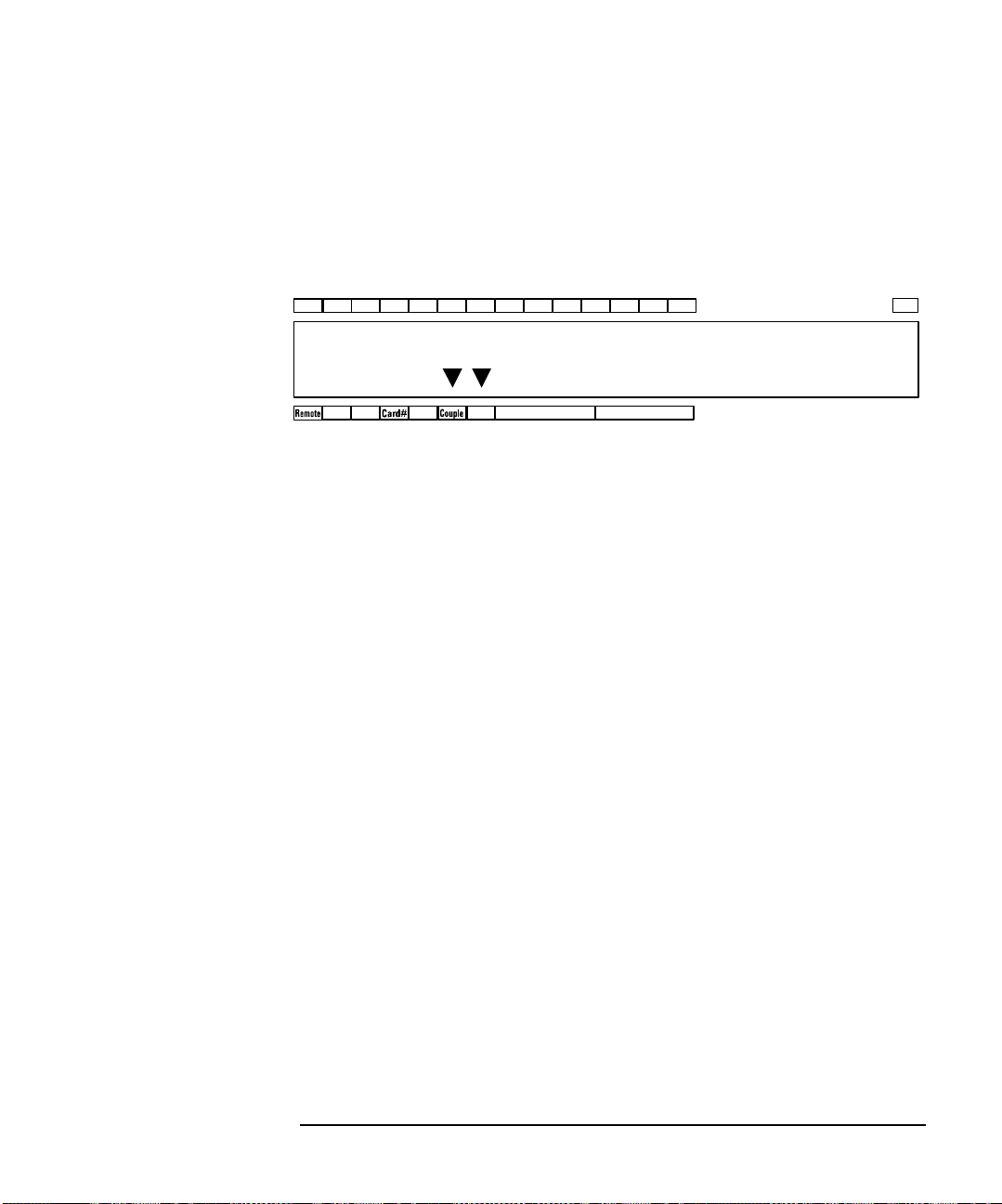
LCD
SequenceRule
GndLock Error GndBias
01 02 03 04 05 06 07 08 09 10 11 12 13 14 Shift
A
FREE
BBM
C
C
G-
-
The LCD displays the setup information and the status information as shown in
Table 3-5. Display example is shown in Figure 3-2.
Figure 3-2 LCD Display Example
The first line shows the input port status, couple port, bias port, ground port, or
ground enabled port.
The second line shows the instrument status and the mode status.
The example of Figure 3-2 notifies you the following information.
• Input 5 and 6 are a couple port.
Front Panel Operation
Display Functions
• Input 12 is the input ground port.
• Input 4 and 7 are the ground enabled input port.
• Channel configuration mode is auto.
• Couple mode is ON.
• Ground mode is ON.
• Connection rule is free.
• Connection sequence is break before make.
Agilent B2200 User’s Guide, Edition 4 3-23
Page 86

Front Panel Operation
Display Functions
Table 3-5 LCD Display Items
Label Description
01 to 14 Port function assigned to the input ports 1 to 14. B (bias port), C (couple port),
G (ground port), - (ground enabled port), or blank (no function).
Shift Shift key status indicator. The triangle mark appears when the sub key is active.
Remote Remote status indicator. The triangle mark appears when the Agilent B2200 is in
the GPIB remote condition.
Lock Key status indicator. The triangle mark appears when the front panel keys are
locked by an external computer.
Error Error status indicator. The triangle mark appears when any error has occurred.
Card# Slot number of the switch module to be monitored. Displays A when the channel
configuration mode is Auto. In the auto mode, the modules installed in the
mainframe from slot number 1 continuously will be controlled as one module. Or
displays 1 to 4 when the channel configuration mode is Normal. The module can
be selected by the
Card Selection key.
Bias Bias mode status indicator. The triangle mark appears when the mode is ON.
Couple Couple mode status indicator. The triangle mark appears when the mode is ON.
Gnd Ground mode status indicator. The triangle mark appears when the mode is ON.
Rule Connection rule, FREE (plural route mode) or SINGLE (single route mode).
Sequence Connection sequence, BBM (Break Before Make), MBBR (Make Before Break), or
NO_SEQ (No Sequence).
NOTE In the remote mode and the default setting, only the Remote, Lock, and Error
indicators are available. To display all information, set the RMT_DSPL function
ON. Refer to “RMT_DSPL” on page 3-33.
3-24 Agilent B2200 User’s Guide, Edition 4
Page 87
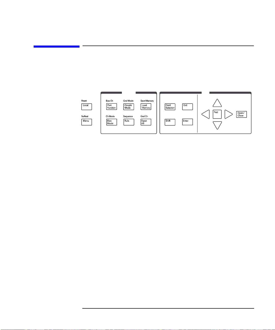
Front Panel Keys
Function Edit
The Agilent B2200 provides LED matrix, LCD, and 18 front panel keys for front
panel operation. The front panel keys are used to change the instrument settings, the
switch conditions, and so on.
Local Sets the Agilent B2200 to the local condition.
Front Panel Operation
Front Panel Keys
Reset
(Shift+Local)
Used to reset the Agilent B2200.
Displays the following message. Press the arrow key to set YES, and then press the
Enter key to reset the instrument.
NO
Menu Displays the setup menu. See “Setup Menu” on page 3-30.
Selftest
Displays the selftest menu. See “Selftest Menu” on page 3-34.
(Shift+Menu)
Agilent B2200 User’s Guide, Edition 4 3-25
Page 88
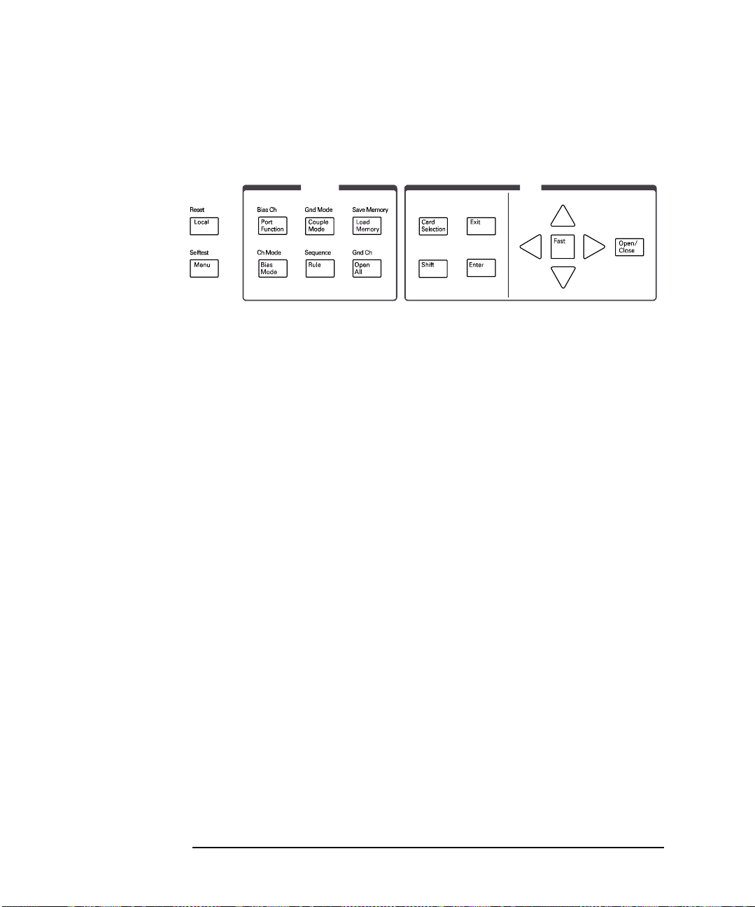
Front Panel Operation
Function Edit
Front Panel Keys
Function key group
The Function key group is used to change the input ports and modes.
Port Function Enters into the port function selection mode. In this mode, the arrow keys, Fast key,
Exit key, and Enter key are available. Other keys will work to exit this mode.
In this mode, move cursor right or left to specify the input port, and press the up or
down arrow key to select the port function, B (bias port), C (couple port), G (ground
port), or - (ground enable port). The port function can be selected when the
corresponding port operation mode (bias mode, couple mode, or ground mode) is set
to ON. The bias mode and the ground mode cannot be set to ON simultaneously.
Bias Ch (Shift+
Port Function)
Displays the following menu.
SET VIEW
• SET displays the following menu. The following functions are used to set the
bias-enabled or bias-disabled channel (output port).
ENABLE DISABLE
The function displays the following message for example. And then press Enter
to bias-enable or bias-disable the channel.
Channel: 01
If there is no enabled or disabled channel, the following message will appear.
Channel: No Channel
• VIEW displays the following message for example, and is used to see the bias
status of the channel.
Channel 01: ENABLED
3-26 Agilent B2200 User’s Guide, Edition 4
Page 89

Bias Mode Sets the bias mode ON or OFF.
When the bias mode is set to ON, the LCD shows which input port is the bias port,
and the input bias port will be connected to the bias-enabled channels that are not
connected to other input port. And LEDs will be turned red to show the bias port
connections.
Front Panel Operation
Front Panel Keys
Ch Mode (Shift+
Bias Mode)
Sets the channel configuration mode AUTO or NORMAL.
Changing the mode will reset the Agilent B2200 settings.
Couple Mode Sets the couple mode ON or OFF.
When the couple mode is set to ON, the LCD shows which input ports are the
couple port.
Gnd Mode (Shift+
Couple Mode)
Sets the ground mode ON or OFF.
When the ground mode is set to ON, the LCD shows which input port is the ground
port, and the input ground port will be connected to the ground-enabled channels
that are not connected to other input port. And LEDs will be turned red to show the
ground port connections. The ground enabled input ports are also connected to the
input ground port. Nothing must be connected to the ground enabled input ports.
Rule Displays the following message. Selects the connection rule FREE (plural route
connections) or SINGLE (single route connection).
FREE
Sequence
(Shift+Rule)
Displays the following message. Selects the connection sequence
Break_Before_Make, Make_Before_Break, or No_Sequence.
Break_Before_Make
Load Memory Displays the following message. Used to select the Agilent B2200 setup data stored
in the internal memory, and loads the data.
Settings: 01 [ ]
Save Memory
(Shift+
Load Memory)
Displays the following message. Used to select the internal memory to store the
Agilent B2200 setup data, and stores the data. Up to eight setup data can be saved.
Settings: 01 [ ]
Open All Displays the following message. Press the arrow key to set YES, and then press the
Enter key to open all relays.
NO
Agilent B2200 User’s Guide, Edition 4 3-27
Page 90

Front Panel Operation
Front Panel Keys
Gnd Ch
(Shift+Open All)
Displays the following menu.
SET VIEW
• SET displays the following menu. The following functions are used to set the
ground-enabled or ground-disabled channel (output port).
ENABLE DISABLE
The function displays the following message for example. And then press Enter
to ground-enable or ground-disable the channel.
Channel: 01
If there is no enabled or disabled channel, the following message will appear.
Channel: No Channel
• VIEW displays the following message for example, and is used to see the ground
status of the channel.
Channel 01: ENABLED
3-28 Agilent B2200 User’s Guide, Edition 4
Page 91
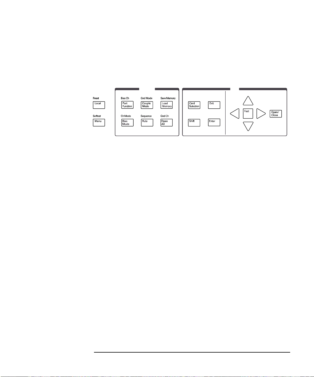
Front Panel Operation
Function Edit
Front Panel Keys
Edit key group
The Edit key group is used to select the switch module to be monitored, move the
cursor in the display, make the setup value effective, return to the previous menu or
display, and so on.
Card Selection Selects the switch module to be monitored on the LCD. The Card# status indicator
will change the slot number (card number) when the
This key is not effective when the Card# indicator shows A (auto configuration
mode).
Shift Enables the sub key function. The sub key label has been printed on the front panel
above the key. The label color is blue.
Card Selection key is pressed.
Exit Returns the display to the previous menu or display without making the setup
effective.
Enter Makes the setup effective, and returns the display to the previous menu or display.
Fast Used with the arrow key. Pressing the
Fast key and an arrow key speeds up changing
the setting value.
arrow keys Moves the cursor on the display, displays another selection for a setup message, or
changes the value of the digit specified by the cursor.
For the LED matrix, moves the blink-LED.
Open/Close When no blink-LED is on the LED matrix, enters into the LED matrix based switch
control mode. The blink-LED will appear. In this mode, the arrow keys and
Fast key
are available. Other keys will work to exit this mode.
When the blink-LED is on the LED matrix, changes the condition, open or close, of
the switch specified by the blink-LED.
Agilent B2200 User’s Guide, Edition 4 3-29
Page 92

Front Panel Operation
Setup Menus
Setup Menus
This section explains the following setup menus displayed by pressing the Menu key
or
Selftest key.
• “Setup Menu”
• “Selftest Menu”
Setup Menu
Press the Menu key. The setup menu will be displayed on the LCD as shown in the
following example. The setup menu is used to change the GPIB address, detect the
couple port automatically, and so on.
[Hardware Configuration]
CONFIG SCAN ERROR RMT_DSPL BEEP >
[Hardware Configuration]
<SCAN ERROR RMT_DSPL BEEP PEN
Press the arrow key to move the cursor to the desired function name. Then, press the
Enter key. The setup message or the sub menu will be displayed. To return to the
previous menu, press the
3-30 Agilent B2200 User’s Guide, Edition 4
Exit key.
Page 93

Function Tree The setup menu provides the following functions.
• CONFIG
• ADDRESS Sets the GPIB address.
• REVISION Displays the firmware revision.
• UNIT Displays the module information of each slot.
• SCAN Detects and sets the input couple ports automatically.
• ERROR
• DISPLAY Displays the error code and error message.
• CLEAR Clears the error buffer.
• RMT_DSPL
• LCD Selects on or off for the LCD display in the remote mode.
• LED Selects on or off for the LED matrix in the remote mode.
• BEEP Selects on or off for the beeper.
• PEN Enables or disables the light pen.
Front Panel Operation
Setup Menus
Agilent B2200 User’s Guide, Edition 4 3-31
Page 94

Front Panel Operation
Setup Menus
CONFIG Displays the sub menu that provides the following functions.
• ADDRESS
Displays the following message.
GPIB Address = Address
Press the arrow key to set the desired GPIB address. Then, press the
make the setup effective, or press the
• REVISION
Displays the following message.
X.XX.XX
where X.XX.XX shows the firmware revision.
To return to the previous menu, press the
• UNIT
Displays the following message.
Slot#: model, X
where # is 1, 2, 3, or 4, model is the model number of the module, X is the
revision of the module.
To display another message, press the arrow key.
To return to the previous menu, press the
SCAN Displays the following message.
NO
Enter key to
Exit key to cancel changing the setup.
Exit key.
Exit key.
Press the arrow key to set YES. Then, press the
couple ports automatically, or press the
Exit key to cancel this operation. The input
Enter key to detect and set the input
couple ports will be the input ports the Kelvin cable is connected.
3-32 Agilent B2200 User’s Guide, Edition 4
Page 95

ERROR Displays the sub menu that provides the following functions.
• DISPLAY
Displays the error code and error message, or No Error.
Front Panel Operation
Setup Menus
To return to the previous menu, press the
Exit key.
• CLEAR
Displays the following message. Press the arrow key to set YES. Then, press the
Enter key to clear the error buffer, or press the Exit key to cancel this operation.
NO
RMT_DSPL Displays the sub menu that provides the following functions.
• LCD
Displays the following message. Press the arrow key to set ON (displays all
status information in the GPIB remote mode) or OFF (displays Remote, Lock,
and Error only). Then, press the
the
Exit key to cancel changing the setup.
Enter key to make the setup effective, or press
OFF or ON
• LED
Displays the following message. Press the arrow key to set ON (enables LED
matrix in the GPIB remote mode) or OFF (disables it). Then, press the
to make the setup effective, or press the
Exit key to cancel changing the setup.
Enter key
ON or OFF
BEEP Displays the following message. Press the arrow key to set the beeper ON or OFF.
Then, press the
Enter key to make the setup effective, or press the Exit key to cancel
changing the setup.
ON or OFF
PEN Displays the following message. Press the arrow key to enable or disable the light
pen. Then, press the
Enter key to make the setup effective, or press the Exit key to
cancel changing the setup.
DISABLE or ENABLE
Agilent B2200 User’s Guide, Edition 4 3-33
Page 96

Front Panel Operation
Setup Menus
Selftest Menu
Press the Shift key and the Menu key. The selftest menu is displayed. The menu is
used to execute the selftest and diagnostics.
[Execute Diagnostics]
SELF_TEST RELAY_TEST KEY BEEPER >
[Execute Diagnostics]
<KEY BEEPER LED PEN GPIB
Press the arrow key to move the cursor to the desired function name. Then, press the
Enter key. The setup message or the sub menu will be displayed. To return to the
previous menu, press the
Function Tree This menu provides the following functions.
• SELFTEST Executes the controller test or displays test result.
• RELAY_TEST Executes the relay test or displays test result.
Exit key.
• KEY Executes the front panel interface test or displays test result.
• BEEPER Executes the beeper test or displays test result.
• LED Executes the LED matrix test or displays test result.
• PEN Executes the light pen test or displays test result.
• GPIB Executes the GPIB test or displays test result.
3-34 Agilent B2200 User’s Guide, Edition 4
Page 97

SELF_TEST Displays the sub menu that provides the following functions.
• EXECUTE
Starts the controller test. Wait until PASS or FAIL is displayed. Then press the
Exit key to return to the previous menu.
• RESULT
Front Panel Operation
Setup Menus
Displays the test result. Press the
Exit key to return to the previous menu.
RELAY_TEST Displays the sub menu that provides the following functions.
Before starting the relay test, disconnect cables from the input connectors. And open
the outputs (end of cable is OK). For the Kelvin cable, disconnect it from the output
connectors.
• EXECUTE
Displays the following message.
Slot1
Press the up or down arrow key to select the module to be tested. Then press the
Enter key to start the relay test, or press the Exit key to cancel this operation.
Number of modules is 2 or more, the relay test will be automatically completed.
However, if the only one module is installed, the following message will appear.
Connect IV1 and 2. Press [Enter].
Then connect a cable between the input 1 and 2, and press
After that, change the cable connection as shown in the displayed message and
repeat this for the other input connections (input 3 and 4, 5 and 6, 7 and 8, 9 and
10, 11 and 12, 13 and 14). Do not forget to open the connectors other than the
specified pair.
Enter key.
• RESULT
Displays the following message (example). Press the up or down arrow key to
display the test result for each module. Press the
Exit key to return to the
previous menu.
Slot1: Not performed yet
Agilent B2200 User’s Guide, Edition 4 3-35
Page 98

Front Panel Operation
Setup Menus
KEY Displays the sub menu that provides the following functions.
• EXECUTE
Displays the following message.
DIAG:KEY Press any key.
Press any front panel key and confirm the LCD display. For example, if you
press the
Port Function key, the following message must be displayed.
DIAG:KEY [Port Function]
Continue this for all keys. After that, press the
Enter key twice for the normal
operation. The test result will be PASS.
If you find any wrong response, press the
Exit key twice. The test result will be
FAIL.
Finally, press the
Exit key to return to the previous menu.
• RESULT
Displays the test result. Press the
Exit key to return to the previous menu.
BEEPER Displays the sub menu that provides the following functions.
• EXECUTE
Starts the beeper test, and displays the following message.
DIAG:BEEP Is beeper making 2 sounds?
Press the
Enter key if the beeper works correctly. The test result will be recorded
as PASS.
If you find any problem, press the
Exit key. The test result will be recorded as
FAIL.
Finally, press the
Exit key to return to the previous menu.
• RESULT
Displays the test result. Press the
Exit key to return to the previous menu.
3-36 Agilent B2200 User’s Guide, Edition 4
Page 99

LED Displays the sub menu that provides the following functions.
• EXECUTE
Starts the LED matrix test, and displays the following message.
DIAG:LED All LED in Orange?
Front Panel Operation
Setup Menus
Press the
Enter key if the all LEDs are lighted in orange. The test result will be
recorded as PASS.
If you find any problem, press the
Exit key. The test result will be recorded as
FAIL.
Finally, press the
Exit key to return to the previous menu.
• RESULT
Displays the test result. Press the
Exit key to return to the previous menu.
PEN Displays the sub menu that provides the following functions.
Before starting the light pen test, connect the light pen to the Agilent B2200.
• EXECUTE
Starts the light pen test, and displays the following message.
DIAG:PEN Point any cross point
Point the light pen to the point you desire and confirm the LCD display. For
example, if you point the input 5-to-output 10 cross point of the Agilent B2200
in the auto configuration mode, the following message must be displayed.
SLOT: 0 INPUT: 5 OUTPUT:10
Continue this for all cross points. After that, press the
Enter key for the normal
operation. The test result will be recorded as PASS.
If you find any wrong response, press the
Exit key. The test result will be
recorded as FAIL.
Finally, press the
Exit key to return to the previous menu.
• RESULT
Displays the test result. Press the
Exit key to return to the previous menu.
Agilent B2200 User’s Guide, Edition 4 3-37
Page 100

Front Panel Operation
Setup Menus
GPIB Displays the sub menu that provides the following functions.
• EXECUTE
Displays the following message.
Open GPIB, then press [Enter]
Disconnect the cable from the GPIB connector on the rear panel, and open it.
Press the
Enter key to start the GPIB test, and wait until PASS or FAIL is
displayed. Then press the
• RESULT
Displays the test result. Press the
Exit key to return to the previous menu.
Exit key to return to the previous menu.
3-38 Agilent B2200 User’s Guide, Edition 4
 Loading...