

Page 1
Agilent AN 372-2
Battery Testing
Application Note
An electronic load can be used to discharge batteries of various
chemistries to determine actual capacity, capacity retention,
and internal impedance.
Page 2
2
Increasing demand for portable DC
power has risen from improvements
in battery and motor design technology. More than ever before, portable
DC powered products have become
available in many diverse applications.
Rechargeable batteries appear in all
types of products from analytical
electronic equipment to power tools
and toys. In some instances, these
diverse applications pose different
requirements on the source of DC
Power. Fortunately, availability of
many types of battery chemistries
yield unique characteristics. Table 1
contains just some of the different
battery types and their advantages.
Whether testing batteries in R&D or
production environments, the test
requirements for each of the different
battery types are basically the same.
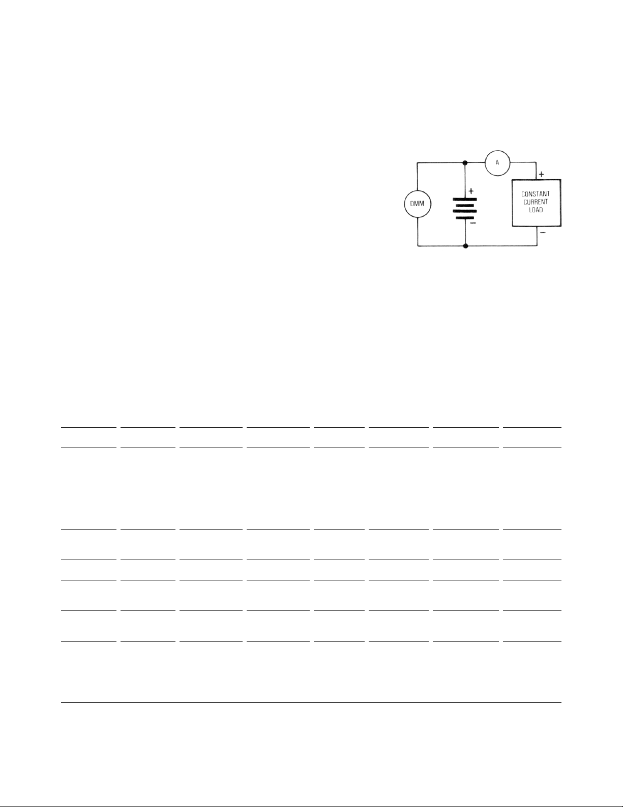
Figure 1 shows a common test configuration. In general, the testing of a
battery involves discharging it over
a period of time to determine several
specifications. This application note
will concentrate on the test of secondary batteries because they require
additional tests involving recharging.
Nickel-cadmium batteries, in particular, are discussed because they are
the most universally used type of
secondary battery in today’s demanding applications.
Introduction
Table 1. Characteristics and Applications of Different Battery Types
Nickel- Gelled Lead Lithium Carbon Alkaline Silver Mercuric
Cadmium Acid Zinc Oxide Oxide
Volts/Cell 1.2 2.0 1.5 to 1 1.5 1.5 1.5 1.4
Applications portable standby service, memory backup, average use good general button-sized button-sized cells
equipment, rechargeable pacemakers, purpose battery cells for watches for watches and
rechargeable electronic and hearing aids hearing aids
door locks,
emergency
locator
transmitters
Charge CC CV, float charge N/A N/A N/A N/A N/A
Method
Cycle Life 500+ cycles 200 cycles N/A N/A N/A N/A N/A
Life 3 mos. 1 year 5 to 10+ years 1 to 5 years 5% loss/yr. 6% loss/yr. 4% loss/yr.
(Charged) (–2%/day)
Operating 20°C to 70°C –20°C to 65°C –55°C to 75°C –5°C to 55°C –30°C to 55°C –20°C to 55°C –10°C to 55°C
Temp.
Performance high discharge high capacity flat discharge, low cost, good energy flat discharge, flat discharge
Comments rate, quick long life, wide sloping density, more energy
charge rate temperature discharge, sloping per unit
range, good low energy discharge volume than
energy density density mercuric oxide
Figure 1. Common Test Configuration
Page 3
3
Seven standard test procedures1are
used to verify certain electrical characteristics of secondary batteries:
1. Rated capacity
2. Capacity retention
3. Effective internal resistance
4. Discharge rate effect on capacity
at –20°C
5. Discharge rate effect on capacity
at 23°C
6. Life cycle performance
7. Extended overcharge
Other miscellaneous tests and procedures also involve discharging a
battery such as: start-up voltage test,
forced-discharge test, timed fast charge
and dump-timed charge. Most battery
tests typically require only about 1%
accuracy unless otherwise specified.
While battery tests do not require
high accuracy, the tests must be very
repeatable. Battery characteristics
change with temperature so it is
important to be able to control and
monitor the temperature, usually to
within ±2 degrees C. Other equipment
requirements to consider are: a current source for charging secondary
batteries, a voltage monitor, a current
monitor, a load for discharge current,
and a time keeping device. More
information about test equipment
is given in the “Test Equipment
Requirements” section later in
this application note.
Note that a battery temperature rise
of more than 5 degrees C above ambient may require supplemental cooling
to prevent battery performance degradation due to elevated temperatures.
1. As specified in ANSI® C18.2-1984,
American National Standards
Rated Capacity
The principal measurement of a
battery’s performance is its rated
capacity. Capacity ratings are attained
in an accelerated test approximating
the battery’s capacity in typical use.
The capacity of a fully charged battery,
at a fixed temperature, is defined as
the product of the rated discharge
current (in amperes) and the discharge
time (in hours) to a specified minimum termination voltage (volts).
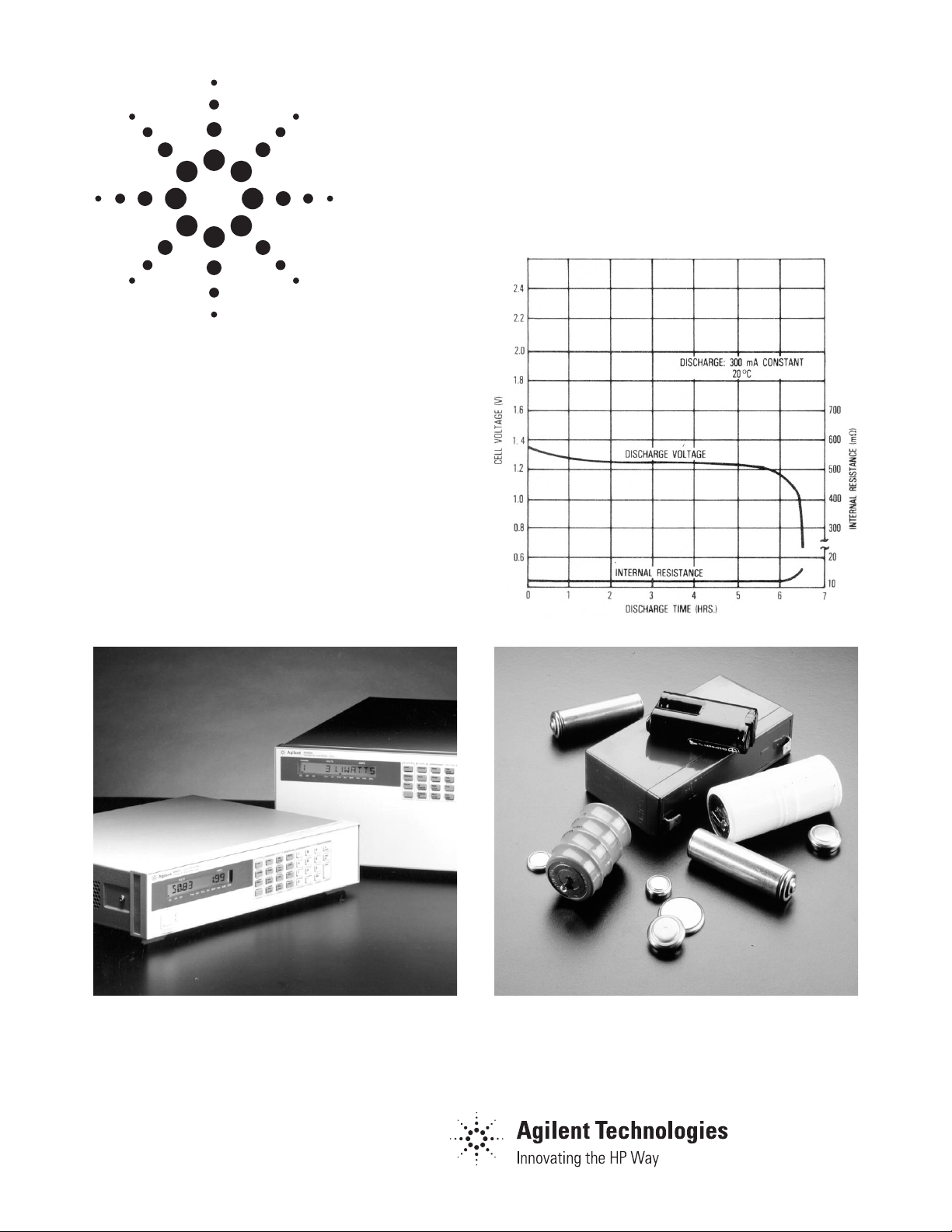
See Figure 2. A battery is considered
completely discharged when it attains
the specified minimum voltage called
the “end of discharge voltage” (EODV).
The EODV for nickel-cadmium batteries
is typically 1.1 to 0.9 Volts.
The term C, or C-rate, is used to
define the discharge current rate (in
amperes), and is numerically equal
to rated capacity, which is expressed
in ampere-hours. The term 1C is
defined as the rate of discharge that
allows a battery to provide its rated
current over a period of one hour.
Application Overview and Test Implementation
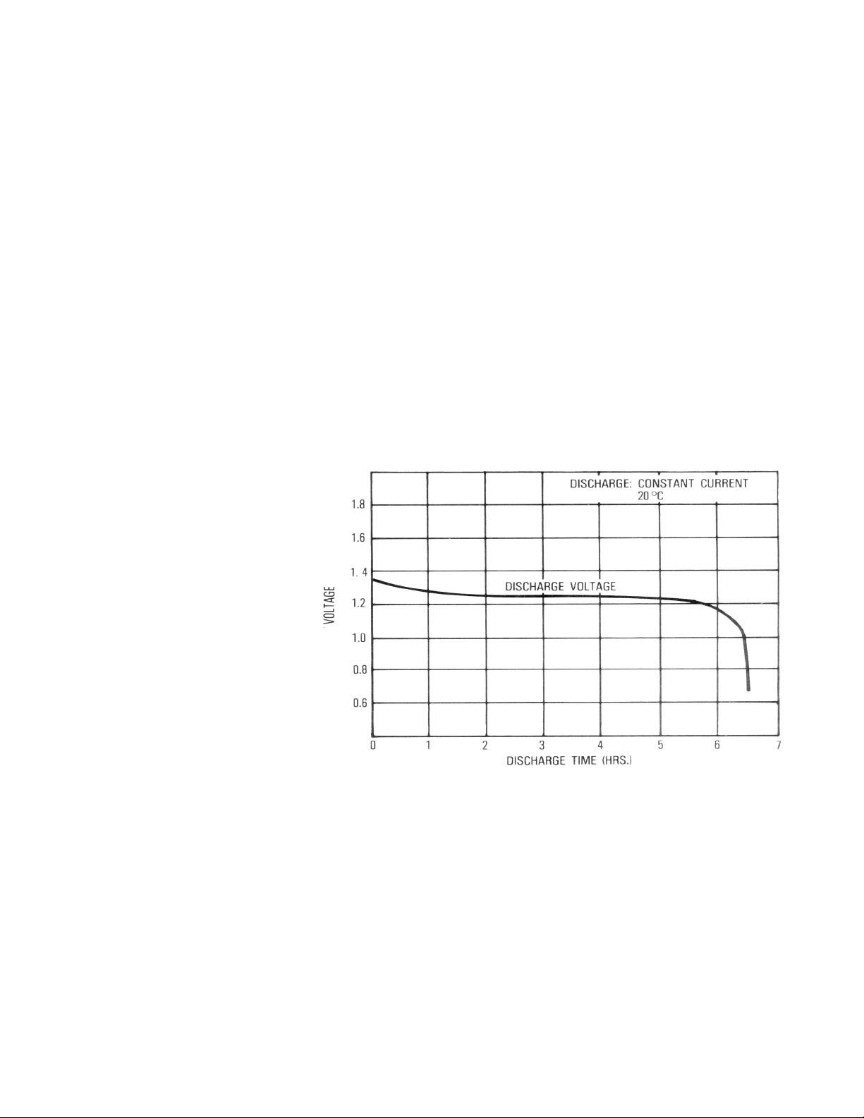
Figure 2. Typical Discharge Curve
Page 4

4
Capacity varies with the rate of discharge as shown in Figure 3. Testing
for how discharge rate affects capacity
is discussed later in more detail.
Generally, lower discharge rates over
longer periods of time yield higher
values of total capacity. It is important to realize that since discharge
rate affects how the value of C is
determined, battery manufacturers
must decide on a standard time of
discharge. Since different values for
capacity can be obtained for the same
battery, capacity is generally determined over a “standard” period of
time— from 5 to 20 hours at discharge
rates from C/5 to C/20. A complete
specification for capacity should
therefore have a C rate and the period
of time that was used to determine
the capacity. For example, Capacity:
450 mAh @ 5 hour rate.
Average and maximum capacities are
obtained by putting the battery through
five successive charge/discharge stabilizing cycles. The batteries are given
five stabilizing cycles where they are
charged, discharged and rested at an
ambient temperature of 23 degrees C.
Batteries are charged at C/10 A for
a period of from 20 to 24 hours and
rested for a period of from 2 to 4 hours.
The batteries are then discharged at
a constant current of 1C amperes to
an EODV of 0.9 volts.
The value of the capacity used in the
following tests is the value obtained
in the fifth stabilizing cycle. Also, the
capacity obtained in the last three
cycles must not be less than that
stated by the manufacturer as rated
capacity (1C).
Capacity Retention
This test characterizes how much of a
fully charged battery’s capacity is
retained over a long period of time
under specific conditions. This time
is sometimes referred to as the “shelf
life” of the battery. This test is not to
be confused with an attempt to characterize the self-discharge effect of
the spontaneous internal chemical
actions in batteries. Self-discharge
occurs regardless of the battery’s
connection to an external circuit.
The procedure to determine the effective capacity retention of a battery is
relatively simple. Immediately following the 5 cycles of capacity measurement, the battery is fully recharged. It
is then stored open circuit for a period of days at a specific temperature.
Then it is discharged at a constant
current rate to an EODV of 0.9 V as
before. The capacity obtained should
not be less than 37% of the rated
capacity for the battery. The number
of days of shelf life are typically provided for values of temperature from
23 degrees C to 50 degrees C.
Figure 3. Effect of Discharge Rate on Capacity
Page 5

5
Effective Internal Impedance
Battery impedance is dependent
on temperature, its state of charge,
and the load frequency. The effective
internal impedance is lower for a fully
charged battery than it is for a discharged one. Having a low internal
resistance is very important when the
battery must support a high current
for a short time. Low temperature, use,
and long storage periods all increase
a battery’s internal resistance. Nickelcadmium batteries also have a high
effective capacitance. Their total effective impedance is so low that, in
applications where they are continuously being “trickel-charged” at rates
from 0.01C to 0.1C, they make excellent ripple filters. Resistance and
impedance tests are explained in the
following paragraphs.
Resistance Test
The battery must be fully charged as
outlined above. Batteries rated 5 Ah or
less are discharged at 10C for 2 minutes and then switched to 1C. The
battery voltage is recorded just prior
to switching and again upon reaching
its maximum value after switching.
All voltage measurements are made at
the terminals of the battery independently of the contacts used to carry
current. The effective internal resistance (R
e
) is then calculated as follows:
R
e
=
∆V
=
VL–V
H
∆
I =IH–IL
I
H, VH = the current and voltage,
recorded just prior
to switching
I
L, VL = the current and maximum
voltage, recorded
after switching
Impedance Test
The battery must be fully charged as
outlined above. An AC current source
(~1 kHz) is applied to the terminals of
the battery. The AC current through
the battery and the voltage across it
are measured. The impedance is simply
calculated as V/I. An interesting
alternative testing method that yields
the same result is to place a varying
(~1 kHz) load across the fully charged
battery instead of the AC power source.
Discharge Rate Effect on Capacity
The rate of discharge has an effect on
the total capacity of a battery. Heavy
discharge rates decrease the total
available capacity of a battery. The
test is done at two temperatures:
–20 degrees C and 23 degrees C.
The battery is first fully charged at
23 degrees C and then immediately
stored for 24 hours at an ambient
temperature of –20 degrees C. It is
then discharged at an ambient temperature of –20 degrees C at a constant current rate of 1C to an EODV
of 0.8 volts. Then the procedure is
repeated at discharge rates of 5C and
C/5. The whole test is then repeated
at a temperature of 23 degrees C to
an EODV of 0.9 volts.
For each of the six discharge cycles,
the manufacturer supplies the value of
capacity to be expected as a percent of
C1. Charging and discharging at temperatures below the specification sheet
recommendation should be avoided.
Life Cycle Performance
Life cycle testing is a measure of
expected battery performance in actual
service. Life cycle performance is
characterized by dynamically loading
the battery in a simulated “real-life”
situation for 50 or more charge and
discharge cycles as follows:
The battery is given five stabilizing
cycles in accordance with the previously outlined procedure.
Life Cycles 1 through 48
1. Charge 11 hours and
20 minutes at C/10
2. Discharge immediately at
1C for 40 minutes
3. No rest
Life cycles 49 and 50
1. Charge for 20 hours at C/10
2. Rest 2 to 4 hours
3. Discharge at 1C to 0.9 volts
EODV
Repetition of Life Cycles
Repeat cycles 1 to 50 as desired.
The capacity at cycle 50, and multiples
thereof, should be no lower than that
stated for this procedure by the manufacturer.
Extended Overcharge
The ability of a battery to withstand
overcharge is determined by charging
the battery at a constant current of
C/10, or at the maximum overcharge
rate recommended by the manufacturer, at an ambient temperature of
23 degrees C for 6 months. The battery should at no time show either
electrolyte leakage or visual evidence
of distortion beyond the standard
maximum dimensions for that battery. When discharged at a constant
current of 1C to an EODV of 0.9V, the
battery should have a capacity equal
to or greater than the extended overcharge capacity specification.
Page 6

6
Miscellaneous Tests
In addition to the tests already mentioned, there are also other miscellaneous tests performed on nickelcadmium batteries. These tests usually
involve high rate charge and/or
discharge.
High rate discharge and charge of
nickel-cadmium batteries is possible
with today’s new and better designed
cells having advanced plate and cell
construction. The low internal resistance of nickel-cadmium batteries
yields high discharge currents. If they
are discharged continuously under
short circuit conditions, however,
self-heating may do irreparable damage. Continuous discharge at rates
greater than 1C should be prevented
to avoid potentially hazardous conditions due to high internal gas pressure build-up.
Very high currents (>2C) can be withdrawn in low duty cycle pulses providing that internal temperatures and
pressures are maintained. Output
capacity in any type of pulse discharge
application is difficult to predict
because of the infinite number of
possible combinations of discharge
time, rest time, and EODV. Simulation
of actual events, as in the Life-Cycle
test, is the best way to quantify a
battery exposed to such conditions.
Many cells can be quick-charged at a
rate up to C/3 in as little as 3 to 5 hours
instead of the standard 12 to 15 hours
at the C/10 rate. High rate charging
should be done under controlled conditions where temperature, voltage,
pressure, or some combination of
these parameters can be monitored to
assure they are within specifications.
One fast-charge method involves
charging the battery at a rate exceeding the specified maximum charge rate
for a finite period of time, after which
the charge rate is reduced to currents
below C 10. This method, called “timed
fast charge,” can indeed give a quick
“boost” charge to a partially discharged
battery, but unfortunately has the
potential of permanently destroying
the battery. The destruction occurs
due to overcharging the battery because its unused capacity is unknown
prior to charging.
A safer variation of the timed fast
charge method is called “dump timedcharge” where the battery is first
fully discharged (“dumped”) to its
EODV before recharging via the “timed
fast charge” method. The “dump
timed-charge” method has the advantage of knowing just how much energy
must be pumped back into the battery
to bring it to full capacity; the risk of
overcharging is therefore eliminated.
One final test, called the “forced discharge test,” determines the safety of
a battery under certain abusive conditions. This test is very dangerous
because, during the test, the battery
is very likely to explode. The test
must be done under extremely well
controlled conditions in an explosion
proof safety chamber to prevent personal injury. The test involves connecting a current source in series
with the battery. The polarity is in
the same direction as normal or short
circuit current flow. See Figure 4. The
current source is set to a value such
that the resultant current flow is
greater than the short circuit current
flow. This test simulates what may
happen if a battery were improperly
installed in a circuit where it may not
be the only source in the application.
Ideally the battery should withstand
the stress, with some degree of margin,
when the test currents are similar to
actual conditions.
Figure 4. Forced Discharge
Page 7

7
From the various tests described
so far, we can see some common
requirements for test equipment. All
the tests require a discharge cycle
using a constant current. A constant
discharge current cannot be attained
with a simple resistor because the
battery voltage changes as current is
drawn from it. An active device is
required, such as an electronic load
with a constant current mode of
operation. Also note that, because
many levels of constant current are
used from test to test, you should be
able to control the electronic load
dynamically as the test demands.
The ability to control the load with a
computer is important because discharge is typically over a long period
of time and, if the test were not automated, constant attendance would be
an unproductive use of an operator’s
time. Long term tests also bring about
another requirement: reliability. The
electronic load must be very reliable
because, if it should fail, the test
would take a long time to repeat.
In battery or single cell testing the
electronic load only has to function
down to the EODV, not zero volts. See
Figure 5. If the minimum load operating voltage is above the EODV for the
battery being tested, two alternatives
are available: stack more than one
battery in series until the required
voltage is reached (Figure 6) or place
a DC power supply (of sufficient voltage and current) in series with the
battery (Figure 7). A power supply
applied in this way is sometimes
called an “offset supply.”
Figure 5. Single Battery Test Configuration
The first alternative (Figure 6) requires
a method of scanning the voltage of
each battery in the stack so that when
any one battery reaches its EODV,
either the test can be halted or the
battery switched out of the circuit
and replaced by a short circuit. Even
as each battery is switched out of the
circuit, the discharge current will
remain the same if the load has a
constant current mode of operation.
Figure 6. Batteries in Series
The second alternative (Figure 7) shows
that using a power supply may be more
desirable because timed fast charge,
dump-timed charge, and forced discharge tests all require a DC power
source anyway. Additionally, a constant current power supply could then
be used to test ampere-hour efficiency
of secondary batteries. This rating is
simply the ratio of the ampere-hours
delivered during discharge to the
ampere-hours required to restore the
initial state of charge to the battery.
Figure 7. Using an Offset DC Power Supply
Voltage and current must be monitored throughout all the tests because
actual battery voltage varies with the
battery chemistry as well as the discharge rate involved. Therefore, a
voltmeter and ammeter are required.
They should be computer controlled
so that the various tests can be halted
when the EODV is reached. If an
ammeter is unavailable, a current
shunt can be used in conjunction with
either a second voltmeter or a scanner.
Test Equipment Requirements
Page 8

Agilent Technologies Electronic
Loads are ideally suited for battery
test applications. Their many features
make the test system easy to configure and provide safe, reliable, and
repeatable operation.
The Agilent 6060A Electronic Load
and 6050A Electronic Load mainframe
have the required constant-current
modes as well as constant-resistance
and constant-voltage modes. Built-in
voltmeters and ammeters eliminate
the need for external meters and provide measurement accuracy which, in
most cases, greatly exceeds the 0.5 to
1% that is typically required.
These electronic loads can be controlled from their front panel, from
a computer via GPIB, or by a 0 to
10 volt analog signal. By varying the
analog control input (up to 10 kHz),
a battery’s effective internal impedance
can be easily measured. The electronic
load’s built-in GPIB interface makes it
simple to connect any computer that
supports GPIB. Agilent’s electronic
loads are not limited to just being
controlled over the bus. Measured
current, voltage, power and complete
status can also be read back over the
bus so that time consuming discharge
tests can be attended automatically.
Agilent’s electronic loads truly provide
a “One Box” solution.
Testing cells down to an EODV of
0.9 volts is easily done with the Agilent
6060A, 6063A, 60501A, 60502A,
60503A, or 60504A Electronic Loads.
While the operating characteristics
of these loads are guaranteed to meet
all specifications above 3 volts, the
DC operating characteristics extend
below 3 volts (see Figure 8). This figure
shows that at 0.9 volts the Agilent
6060A Electronic Load is capable of
reliably drawing up to 27 amperes.
That means an 80 Ah battery could
be discharged to an EODV of 0.9 volts
at a discharge rate of C/3. For applications requiring V/I characteristics
below the operating curve of Figure 8,
Agilent offers a full family of DC power
supplies to be used as an offset supply.
Agilent’s full featured Electronic Load
Family offers quality and reliability
backed with a three year warranty.
Refer to the 1990/91 DC Power Supply
Catalog with Electronic Loads (Part
Number 5952-4203) for more information about Electronic Loads.
By internet, phone, or fax, get assistance
with all your test and measurement needs.
Online Assistance
www.agilent.com/find/assist
Phone or Fax
United States:
(tel) 1 800 452 4844
Canada:
(tel) 1 877 894 4414
(fax) (905) 206 4120
Europe:
(tel) (31 20) 547 2323
(fax) (31 20) 547 2390
Japan:
(tel) (81) 426 56 7832
(fax) (81) 426 56 7840
Latin America:
(tel) (305) 269 7500
(fax) (305) 269 7599
Australia:
(tel) 1 800 629 485
(fax) (61 3) 9210 5947
New Zealand:
(tel) 0 800 738 378
(fax) (64 4) 495 8950
Asia Pacific:
(tel) (852) 3197 7777
(fax) (852) 2506 9284
Product specifications and descriptions in this
document subject to change without notice.
Copyright © 1988, 1991, 2000 Agilent Technologies
Printed in U.S.A. 9/00
5952-4191
Battery Testing with Agilent Electronic Loads
Figure 8. Operating Characteristics of an Agilent Electronic Load
 Loading...