

Page 1

Page 2

Oscilloscopes 50
Oscilloscope Probes & Accessories 82
Signal Analyzers 94
EMI/EMC 141
Noise Figure Analyzers 144
Network Analyzers 149
Logic Analyzers 179
System and Protocol Test 191
Bit Error Ratio Testers 203
Optical/Transmission 212
Digital Multimeters 216
Power Meters 233
Electronic Counters 243
LCR & Resistance Meters 250
Component Test Instruments 259
Signal Source Analyzer 268
Dynamic Signal Analyzer 270
OSCILLOSCOPES,
ANALYZERS, METERS
3
Page 3

50
3
Overview
Overview
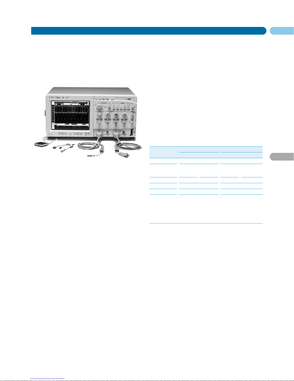
Oscilloscopes
English URL www.agilent.com/find/products
Accelerate Your Troubleshooting
Agilent oscilloscopes are designed to help
you accelerate the troubleshooting process.
Based on input from customers around the
world, Agilent has engineered features and
unique capabilities that will enable you to
keep pace with the rapid changes in
technology, yet are easier to use than most
competitive products. The result is you
spend more time troubleshooting your
design and less time fighting your
oscilloscope.
• Real-time oscilloscopes with bandwidths
from 20 MHz to 13 GHz
• Sampling oscilloscopes with bandwidths
up to 80 GHz
• Unique mixed signal scopes with
integrated oscilloscope and logic
analysis features
• MegaZoom technology for fast and deep
memory all the time
Agilent Offers a Wide Range of Oscilloscopes
Model Bandwidth Sample Rate Analog Channels Digital Channels Memory Depth
Handheld 20 – 40 MHz 200 MSa/s 2 — 125 Kpts
U1600A Series
Economy 60 – 200 MHz 500 M – 1 GSa/s 2 — 4 Kpts
DSO3000 Series
Portable 100 – 500 MHz 2 – 4 GSa/s 2 or 4 — 1 Mpts standard
DSO5000 Series
High Performance Portable 100 MHz – 1 GHz 2 – 4 GSa/s 2 or 4 16 optional Up to 8 Mpts
MSO/DSO6000 Series (2 Mpts standard)
Low Profile Scope 100 MHz – 1 GHz 2 – 4 GSa/s 4 16 optional 2 Mpts standard
DSO 6000L Series
Mainstream Lab 600 MHz – 1 GHz 2 – 4 GSa/s 4 16 optional Up to 128 Mpts
Infiniium 8000 Series (8 Mpts standard)
High Performance Lab 2 GHz – 13 GHz 20 – 40 GSa/s 4 — Up to 2 Mpts
Infiniium DSO80000B Series at 20 G – 40 GSa/s
High Bandwidth Sampling 3 GHz – 80 GHz 40 kS (sequential) 4 — Configurable
86100C Infiniium DCA-J Series
Page 4
51
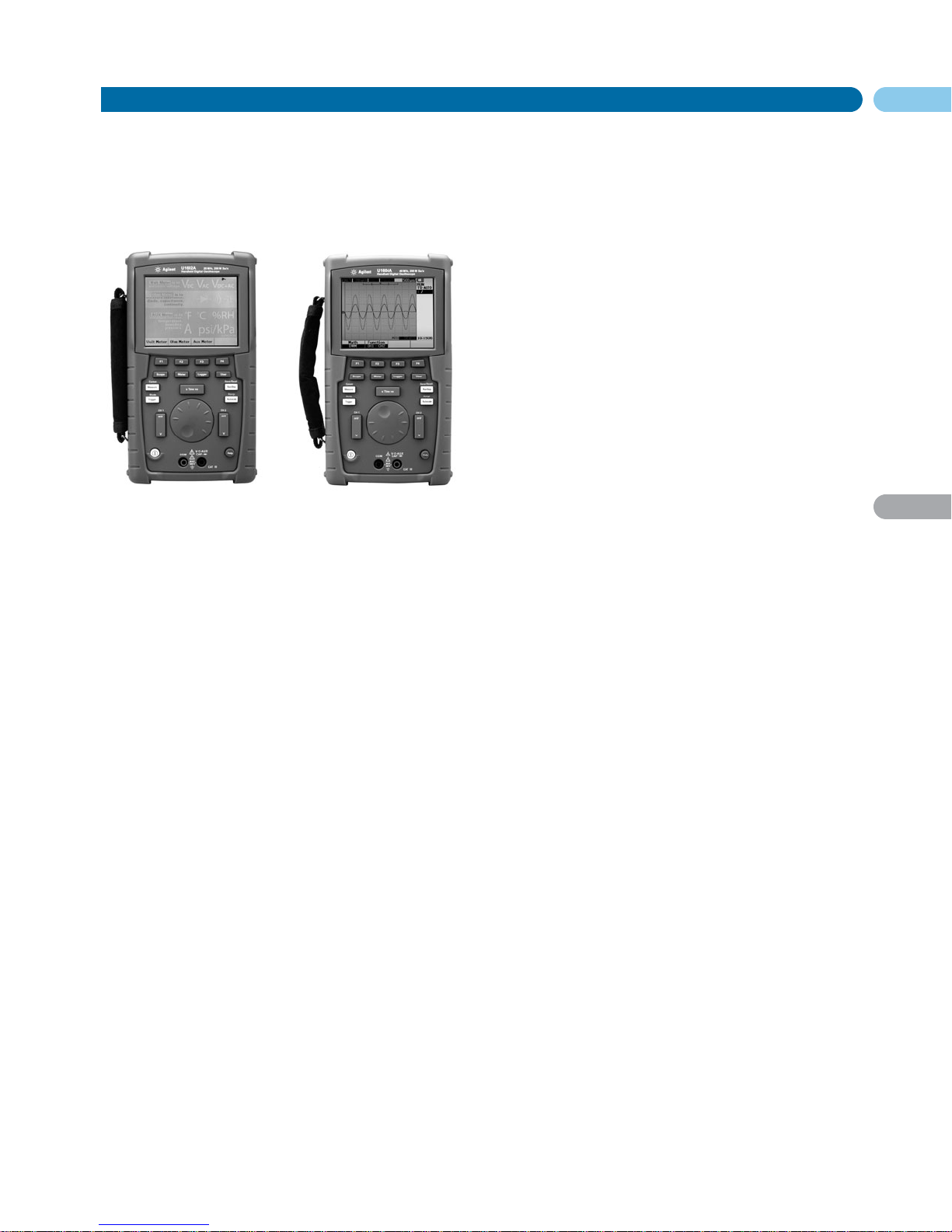
U1602A
U1604A
Handheld Oscilloscopes
Oscilloscopes
The Agilent U1600A Series digital handheld oscilloscopes include
two models: the U1602A with 20 MHz bandwidth and U1604A with
40 MHz bandwidth. The U1600A Series is designed to address portability in multi-industrial automation, process control, facility maintenance and automotive-service industries. Bringing value and high
performance, it was voted the No. 1 Product of the Year by readers of
Elektronik, one of Europe’s key electronics magazines.
Clearly Distinguish your Waveforms
Clearly distinguish the waveforms between channels with U1600A’s
large 4.5-inch, 320x240 resolution LCD color display.
Effective Capture and Precise Isolation of Signals
With real-time sampling rates up to 200 MSa/s, you can achieve
effective capture of signal anomalies, deviations and glitches. The
U1600A Series deep memory of 125 KB enables capture of nonrepeating signals over long time spans, and zooming into the segment of interest to uncover even the most subtle details of the signal.
Advanced triggering types such as edge, pulse width, pattern and
video, further enable quick isolation of critical events.
Quick Waveform Analysis with FFT and Dual Waveform
Math Functions
Add and subtract multiple channel signals with U1600A’s Dual
Waveform Math function. With the U1604A’s Fast Fourier
Transform (FFT) function, you can view waveforms in four windowing techniques: Rectangular, Hanning, Hamming, and BlackmanHarris.
22 Automatic Measurements
Make and display four different measurements simultaneously with
up to 22 automatic measurements.
Save and Recall Waveform and Setup Memories
Save/recall up to 10 waveforms and configuration setups at anytime
so you can save test time. As an option, you can also store your waveforms and setups onto a USB flash drive through the instrument's
USB host port.
Built-in DMM Functions
The U1600A Series can function as a 6000 count resolution, true
RMS digital multimeter (DMM) with a broad range of measurement
functions — including voltage, resistance, capacitance, diode, continuity test and temperature measurements.
Built-in Data Logger Function
The U1600A Series comes with a standard USB 2.0 full speed interface. This, together with the bundled PC Link application software,
enables remote control and data transfer to PC. With the PC Link
application software, you can also perform storing, retrieval and
documentation of your data.
Multi-language Quick Help Support
The built-in Quick Help menu is designed to give you instant assistance, and is available in English, German, Italian, Spanish,
Portuguese, French, Korean, Traditional Chinese, Simplified
Chinese, and Japanese.
Scope Specifications
1
Vertical System: Scope Channels
Bandwidth (–3 dB)
U1602A: DC to 20 MHz
U1604A: DC to 40 MHz
Scope Characteristics
2
Acquisition : Scope Channels
Maximum Sample Rate
U1602A: 200 MSa/s interleaved, 100 MSa/s each channel (50 s/div to
125 ns/div)
U1604A: 200 MSa/s interleaved, 100 MSa/s each channel (50 s/div to
250 ns/div)
Equivalent Sample Rate
U1604A: 2.5 GSa/s (125 ns/div to 10 ns/div)
Vertical Resolution
8 bits
Maximum Memory Depth
125 kilobytes/channel
Peak Detection
5 ns
Average
Selectable in average number of 2, 4, 8, 16, 32, 64, 128, 256
Vertical System: Scope Channels
Analog Channels
Channel 1 and Channel 2 simultaneous acquisition
Rise Time
U1602A: <17.5 ns
U1604A: <8.8 ns
Vertical Sensitivity
5 mV/div to 100 V/div (1:1 scope probe)
50 mV/div to 1 kV/div (10:1 scope probe)
500 mV/div to 10 kV/div (100:1 scope probe)
Maximum Input
CAT III 300 V
rms
(up to 400 Hz) from terminal to ground
Offset/Dynamic Range
± 5 div
Input Impedance
1 MW || <20 pF
Coupling
AC, DC, GND
Maximum Probe Input
1x CAT III 300 VAC 10x, 100x CAT III 600 VAC
Noise Peak-to-peak
3% of full scale or 5 mV, whichever is greater
DC Vertical Offset Accuracy
±0.2 div ±2 mV ±0.5% offset value
Single Cursor Accuracy
4% full scale
Dual Cursor Accuracy
4% full scale
1
All specifications are warranted. Specifications are valid after a 30-minute warm-up
period and within ±10°C from firmware calibration temperature.
2
All characteristics are typical performance values and are not warranted. Characteristics
are valid after a 30-minute warm-up period and within ±10°C from firmware calibration
temperature.
3
• 3-in-1 solution: 2-channel oscilloscope, true RMS DMM,
data logger
• Large 4.5-inch LCD color display
• Up to 200 MSa/s real time sampling rate
• 125 KB/channel memory depth
• Zoom and Dual Waveform Math functions (includes FFT function
for U1604A)
U1602A U1604A
Page 5

52
U1602A
U1604A
Handheld Oscilloscopes (cont.)
Oscilloscopes
Horizontal System
Range
U1602A: 50 ns to 50 s/div
U1604A: 10 ns to 50 s/div
Resolution
U1602A: 2 ns
U1604A: 400 ps
Delay Range (pre-trigger)
15 divisions
Delay Range (post-trigger)
1000 divisions
Analog t Accuracy
±3% reading ± 0.4% screen
Modes
Main, XY, Roll
RMS Jitter
5% of horizontal scale or 5 ns whichever is higher
Trigger System
Source
Channel 1 and Channel 2
Modes
Auto, normal, single
Selections
Edge, pulse width, pattern, video
• Edge: Trigger on a rising or falling edge of any source
• Pattern: Trigger at the beginning of a pattern of high, low levels and
rising or falling edge established conditions of AND, OR, NOR and
NAND between the channels
• Pulse width: 200 ns to 10 s. Trigger when a positive or negative pulse
width of any source larger than, less than, equal to or not equal to
duration
• Video: Video trigger sensitivity: 0.7 division trigger level. Available to
both Channel 1 and Channel 2. Analog progressive and interlaced video
standards including NTSC, PAL and SECAM. Positive or negative sync
pulse polarity. Modes – all fields, even fields, odd fields or line 5 – 263
within a field
Range
±4 divisions from center screen
Level Accuracy
±0.5 divisions
Trigger Sensitivity
DC to 5 MHz: 0.5 divisions
U1602A: 5 MHz to 20 MHz – 1 division
U1604A: 5 MHz to 40 MHz – 1 division
Coupling
DC, AC (<1 Hz), HF reject (>50 kHz), LF reject (<30 kHz), Noise reject
Measurement System
Autoscale
Finds and displays all active scope channels, sets edge trigger mode on
highest numbered channel, sets vertical sensitivity on scope channel.
Requires voltage >20 mVp-p, 0.5% duty cycle and frequency >100 Hz
Automatic Measurement
Measurements continuously updated
Voltage
Peak-to-peak, maximum, minimum, amplitude, top, base, +overshoot,
–overshoot, preshoot, RMS, mean and one cycle mean
Time
Frequency, period, +width, –width and +duty cycle and –duty cycle on any
channel
Rise time, fall time, delay and phase shift
Cursors
Manually place readout of horizontal (X, X) and vertical (Y, Y)
Waveform Math
CH1 + CH2, CH1 – CH2, CH2 – CH1
FFT
1
Window
Rectangular, Hamming, Hanning, Blackman-Harris
Amplitude Display
Selectable in amplitude display of 1 dB, 2 dB, 5 dB, 10 dB
Digital Multimeter Specifications
2
± (% of reading + % of range)
DC Voltage
Up to 600 V
AC Voltage
Up to 600 V
AC + DC Voltage
Up to 600 V
Resistance
Up to 60 MΩ
Capacitance
Up to 300 µF
Diode
Up to 1 V
Measurement Characteristics
Full Scale Reading
6000 count
DC Voltage, True RMS AC Voltage
Maximum input voltage, 600 V
rms
CAT II, 300 V
rms
CAT III
DC coupled input coupling
Continuity
Beeper <60 Ω in 600 W range
Data Logger
Source
Digital multimeter measurements
Range
10 divisions
Record Size
250 points
Time Span
Auto range 150 seconds to 20 days
Time Reference
Time from start
Record Method
Selectable minimum, maximum and average
Display System
Display
4.5-inch diagonal color CSTN LCD
Resolution
320 x 240 pixels
Control
Contrast control, infinite persistence on/off
Built-in Help System
Functional help displayed by pressing help button
Real Time Clock
Time and date (user adjustable)
Storage
Save/Recall (non-volatile)
Up to 10 setups and traces
Key Literature & Web Link
Data Sheet, p/n 5989-5576EN
For more information on U1600A Series www.agilent.com/find/U1600A
To watch U1600A Series interactive product showcase
www.agilent.com/find/U1600A_showcase
Ordering Information
U1602A 20 MHz Digital Handheld Oscilloscope
U1604A 40 MHz Digital Handheld Oscilloscope
Includes U1560A Scope Probe (1:1), U1561A Scope Probe (10:1), U1571A
Ni-MH Battery Pack 7.2 V, 4500 mA, U1580A DMM Test Lead, Ground
Alligator Clip, Medium Jaw Alligator Clip, Hook Clip, USB Cable, Power
Cord and AC Adapter, Quick Start Guide, Product Reference CD-ROM
(includes User’s and Service Guide, Quick Start Guide and PC Link
Application software), Certificate of Calibration, Test Report
Accessories
U1560A Scope Probe (1:1) CAT III 300 V
U1561A Scope Probe (10:1) CAT III 600 V
U1571A Ni-MH Battery Pack 7.2 V, 4500 mA
U1580A DMM Test Lead
U1590A Soft Casing
U1562A Scope Probe (100:1) CAT III 600 V with ground alligator clip
Option 001 USB Host Capability
1
FFT function is only available for U1604A model.
2
For temperature between 0°C to 18°C and 28°C to 50°C , add 0.1% of reading + 0.02% of
range for every degree Celsius.
English URL www.agilent.com/find/products
3
Page 6
53
3
DSO3062A
DSO3102A
DSO3152A
DSO3202A
N2860A
N2861A
N2862A
N2863A
10073C
N2774A
N2775A
10076A
N2771A
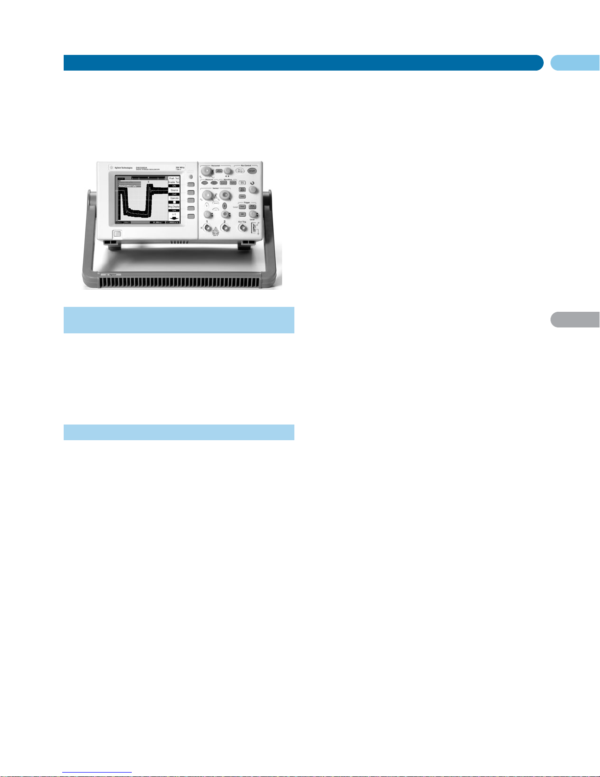
3000 Series Economy Oscilloscopes
Oscilloscopes
English URL www.agilent.com/find/products
Full-featured Oscilloscopes for the Smallest
Budgets
Agilent’s 3000 Series oscilloscopes give you an affordable way to see
what’s happening in your designs. Developed with the features you
need to make your job easier.
Need flexibility? Choose from four models with bandwidths
ranging from 60 MHz to 200 MHz. To give you the debugging power
you need, each oscilloscope comes standard with advanced features
including sophisticated triggering, automatic measurements, digital
filtering, sequence mode acquisition, math functions (including
FFTs), stored setups and waveforms, mask testing and much more.
See your Signals More Clearly
All 3000 Series models have color displays to allow you to quickly
identify your signals, and the large size – 15 cm (5.9 in) with 320 x
240 resolution – makes it easier for you to see more information.
The 3000 Series’ delayed sweep also lets you see more details
in your design. You can view a long record, then window in on the
section of the signal of interest.
All the Features you Need
All 3000 Series scopes include the standard features you need to get
your job done easier and faster:
Autoscale – Autoscale lets you quickly display any active signals,
automatically setting the vertical, horizontal and trigger controls
for the best signal display.
Advanced Triggering – Includes edge, pulse width and line-selectable
video, to help you isolate the signals you want to see.
Waveform Math with FFTs – Analysis functions include addition, subtraction, multiplication, and Fast Fourier Transforms with four
windows (Hanning, Hamming, Blackman-Harris and rectangular).
Auto Calibration – Automatically calibrates the oscilloscope’s vertical
and horizontal systems.
Multi-language Interface – Operate the oscilloscope in the language of
your choice. Language support includes simplified and traditional
Chinese, Japanese, Korean, French, German, Italian, Portuguese,
Russian, Spanish and English.
Digital Filtering – Digital filtering selections include low pass, high
pass, band pass, and band reject filters. Limits are selectable
between 1 kHz and the bandwidth of your oscilloscope model.
Ten Waveform and Setup Memories – Store waveforms or commonly
used setups for future reference and use.
Mask Testing – Automatically compares incoming signals with a predefined mask, clearly highlighting signal changes.
• Large 15-cm (5.9-in) color display
• Up to 1 GSa/s sample rate and 4 k points of memory
• Advanced triggering including edge, pulse-width, and
line-selectable video
• 20 automatic measurements and 4 math functions with FFTs
• USB connectivity and Scope Connect software, standard
• GPIB and RS232 connectivity available
• Mask test standard
Sequence Mode – Frame an area of interest on your signal and record
up to 1,000 frames for playback.
3-year Warranty – All 3000 Series scopes include a full 1-year
warranty with optional 3-year warranty coverage.
Easy to Set Up and Use – Dedicated, color-coded knobs for vertical
sensitivity, offset, and time base settings make it easy to set up and
use. Front-panel keys for triggering functions are also grouped to
make your job easier.
Specifications
Bandwidth
DSO3062A: 60 MHz
DSO3102A: 100 MHz
DSO3152A: 150 MHz
DSO3202A: 200 MHz
Real Time Sample Rate
2 channels interleaved: 1 GSa/s
Each channel 500 MSa/s
Channels
2
Display
Color, 320 x 240 1/4 VGA LCD; H: 88 mm, W: 116 mm
Memory
4 kpoints per channel
Vertical Resolution
8 bits
Vertical Sensitivity
2 mV/div to 5 V/div
DC Gain Accuracy
±3% for 10 mV/div to 5 V/div; ±4% for 2 mV/div to 5 mV/div
Vertical Zoom
Vertical expand
Maximum Input Voltage
300 V
rms
CAT II; derated at 20 dB/decade above 100 kHz to 13 V p-p AC at
3 MHz and above
Time Base Range
2 ns/div to 50 s/div (5 ns/div to 50 s/div in DSO 3062A)
BW Limit
~ 20 MHz
Input Coupling
DC, AC, Ground
Input Impedance
1 MΩ: 13 pF
Time Base Accuracy
100 ppm
Acquisition Modes
Normal: Displays sampled data directly to the screen in real time
Averaging: Selectable from 2, 4, 8, 16, 32, 64, 128 or 256
Peak detect: Captures high-frequency glitches as narrow as 10 ns when
viewing signals at slower sweep speeds (slower than 5 µs/div)
Sweep Modes
Auto, Normal
Trigger Coupling
AC, DC, LF reject, HF reject
Trigger Modes
Force: Triggers immediately when front-panel button is pushed
Edge: Triggers on the positive or negative slope on any channel
Video: Triggers on one of three standard television waveforms: NTSC, PAL,
SECAM
Pulse triggering: Triggers on a pulse width greater than, equal to, or less
than a specified time limit, with time limits ranging from 20 ns to 10 s
Trigger Source
Ch 1, 2, Ext, Ext/5, Line (edge mode only)
Cursors
Modes: Manual, auto, track
Type: Time and voltage
Measurements: ΔT, ΔV, frequency
Automatic Measurements
20 plus 5-digit hardware counter
Voltage: Peak-to-peak, maximum, minimum, average, amplitude, top,
base, V
rms
, overshoot, preshoot
Time: Frequency, period, +width, –width, +duty cycle, –duty cycle, rise
time, fall time, delay, phase
Math Functions
Add, subtract, multiply, FFT
Page 7

54
DSO3062A
DSO3102A
DSO3152A
DSO3202A
N2860A
N2861A
N2862A
N2863A
10073C
N2774A
N2775A
10076A
N2771A
3000 Series Economy Oscilloscopes (cont.)
Oscilloscopes
FFT
Window modes: Hanning, Hamming, Blackman-Harris, rectangular
Sample size: 1024 points
Autoscale
Single button automatic setup of all channels
Display
1/4 VGA (320 x 240), passive color LCD with adjustable brightness
Interpolation
Sin(x)/x
Display Types
Dots and vectors
Persistence
Off, infinite
Format
YT and XY
I/O
Optional ports: GPIB, RS-232
Maximum data transfer rates: GPIB: 500 kbytes/sec
Physical Size
30 cm wide x 15 cm high x 29 cm deep (without handle)
34.6 cm wide x 18.2 cm high x 29 cm deep (with handle)
Weight Net
4.8 kgs (10.5 lbs)
Shipping
7 kgs (15 lbs)
Accessories
Accessories Included
Quick Start manual, CD-ROM with User’s Guide (French, German,
Japanese, Korean, Russian, Simplified Chinese, and English) and
Programmer’s Manual, power cord, accessory pouch, two passive probes,
Scope Connect Software
Additional Probes
N2862A 10:1, 150 MHz passive probe
N2863A 10:1, 300 MHz passive probe
10070C 1:1, 20 MHz passive probe
N2774A 50 MHz current probe, ac/dc
N2775A Power supply for N2774A
10076A 100:1, 4 kV, 250 MHz high-voltage probe
N2771A 1000:1, 15 kV, 50 MHz high-voltage probe
Optional Accessories
N2861A Communications Module
Provides GPIB and RS-232 connectivity and pass/fail output for automatic
testing.
Warranty Options
All models include a standard 1-year warranty. Contact your local sales
office for prices of extended warranty options.
R-51B-001-3C: 1-year return-to-Agilent warranty, extended to 3-years
Key Literature & Web Link
3000 Series Oscilloscopes Data Sheet, p/n 5989-2235EN
www.agilent.com/find/DSO3000
Ordering Information
DSO3062A 60 MHz, 2 Channel Oscilloscope
DSO3102A 100 MHz, 2 Channel Oscilloscope
DSO3152A 150 MHz, 2 Channel Oscilloscope
DSO3202A 200 MHz, 2 Channel Oscilloscope
N2860A 3000 Series Connect Software
N2861A Communications Module
N2862A 150 MHz Passive Probe
N2863A 300 MHz Passive Probe
10070C 1:1, 20 MHz Passive Probe
N2864A Rack Mount Kit
N2774A 50 MHz Current Probe, ac/dc
N2775A Power Supply for N2774A
10076A 100:1, 4 kV, 250 MHz High-voltage Probe
N2771A 1000:1, 15 kV, 50 MHz High-voltage Probe
N2865A USB Host Modules (standard with purchase)
English URL www.agilent.com/find/products
3
Page 8
55
3
5000 Series
6000 Series
8000 Series
80000 Series
Integrated Analog, Digital and Serial Test
Oscilloscopes
• Analog signal viewing with fast and responsive
MegaZoom memory
• Digital signal triggering and analysis
• Serial triggering and decode for I
2
C, SPI, CAN, LIN, Flex Ray
and more
English URL www.agilent.com/find/products
Analog: Up to 4 Channels with 4 GaS/s Sample
Rate and 1 GHz Bandwidth
MegaZoom Technology
MegaZoom deep memory captures long, non-repeating signals and
maintains high sample rates, allowing you to quickly zoom in on
areas of interest. Sample rate and memory depth go hand-in-hand.
Deep memory in oscilloscopes sustains a high sample rate over
longer time spans. MegaZoom also supports a high-resolution XGA
display system and maps the deep memory to 256 levels of color
intensity grades, delivering unmatched real-time insight into signal
details.
Signal Integrity – Probing
Probing high-frequency signals becomes more challenging as the
variety of test points and the frequencies of the signals continue to
grow. Probes need to be lightweight, small, affordable, and offer the
accessories and probe tips you require to get your job done easily.
Agilent has a wide range to meet your needs.
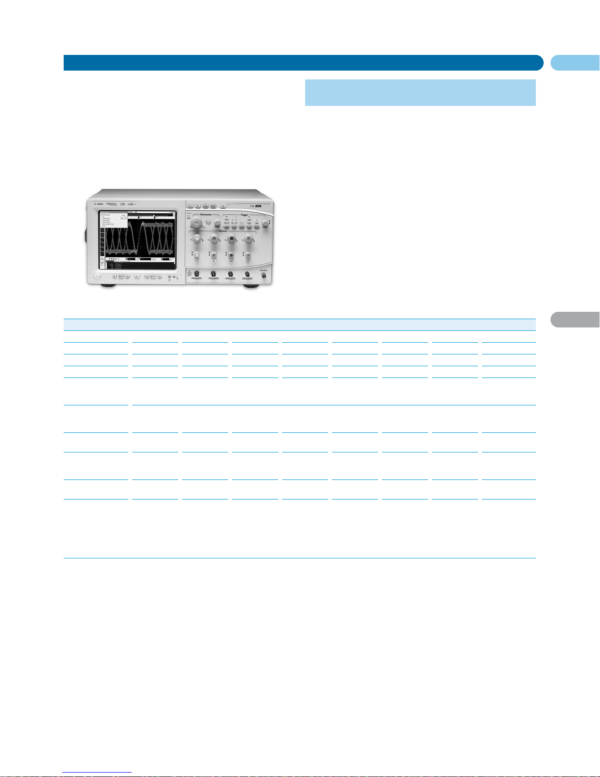
Digital: 16 Digital Timing Channels and Mixed
Signal Triggering
With many of today’s designs containing a mix of signal types and
speeds, it’s often critical to capture and compare multiple cycles of
digital signals along with slower analog signals. But doing so often
requires an instrument that can deliver more resolution and memory
than a traditional DSO can provide.
Easily See Complex Interactions with an MSO
Mixed signal oscilloscopes (MSOs) with 2 or 4 scope channels plus
16 logic channels combine the detailed signal analysis of a scope
with the multi-channel timing measurements of a logic analyzer.
Full-width Pattern Triggering
Flexible triggering capabilities across all scope and logic channels so
you can easily isolate and analyze complex signals in your mixed
analog and digital designs.
View Scope – Logic and Scope Correlation
Easily make time-correlated measurements between an Agilent logic
analyzer and an Agilent 5000, 6000, 8000 or 80000 Series Scope.
Easily view and analyze time-correlated logic and scope waveforms
integrated into a single logic analyzer waveform display. Global
markers track between two instruments.
Serial: Hardware-accelerated Decode and Trigger
for I2C, SPI, CAN, LIN and Flex Ray
As more and more component interfaces move from parallel to serial
on both low- and high-speed buses, Agilent is offering more serial
triggering and decode options on oscilloscopes.
Serial Bus Triggering and Decoding
Trigger on the industry’s most popular serial bus standards including I
2
C, SPI, CAN, LIN, FlexRay and USB. Decode options display
responsive, on-screen decode of serial bus traffic. Select from a suite
of hardware triggers for the ability to isolate specific events with
pin-point accuracy, then enable decode to validate serial bus activity
in real-time.
Hijack Infrequent Errors
Fast acquisition speed combined with hardware-accelerated decoding increases your probability of capturing elusive events. Agilent
oscilloscopes can help you catch that intermittent problem before it
becomes an intermittent customer complaint or quality concern.
Page 9
56
MegaZoom
DSO5012A
DSO5014A
DSO5032A
DSO5034A
DSO5052A
DSO5054A
Oscilloscopes, 100 MHz to 500 MHz 5000 Series Oscilloscopes
Oscilloscopes
• 1Mpts deep memory – High sustained high sample rates means
that you don’t lose signal resolution – even when acquiring long
periods of time
• 100,000 waveforms/sec update rate – Fast waveform update
rates provide you with unsurpassed ability to capture and view
infrequent and intermittent problems
• XGA display with 256 levels of intensity – A high-definition
display system improves your ability to view small signal
anomalies
• Full connectivity, including USB: USB, LAN, GPIB, and XGA videoout are all included standard
• LXI class C compatible
Users of general-purpose portable oscilloscopes have, until now, had
to work through everyday debug tasks using oscilloscope technology
from the 1990s. Engineers need tools capable of handling today’s
design challenges. The new 5000 Series oscilloscopes tackle these
needs with responsive deep memory, a high-definition display
system, and a superior ability to capture signal transients.
Traditional bench scopes are great for characterizing things that you
know about. Agilent’s patented deep memory and fast waveform
update rate help you find the bugs that you don’t know about.
MegaZoom III Deep Memory
Based on the same technology that powers Agilent’s market leading
high end oscilloscopes the deep memory that is available in the 5000
oscilloscope is based on MegaZoom technology. 1 Mpt of MegaZoom
deep memory comes standard so you can capture long, non-repeating signals, while maintaining high sample rates and good timing
resolution.
Don’t Take our Word for It
Compare the 5000 Series with your current bench scope.
View an on-line product demonstration or schedule a hands-on
evaluation by visiting our web site at: www.agilent.com/find/5000ct2
This memory updates up to 100,000 times per second, so you can
capture intermitted glitches with confidence.
English URL www.agilent.com/find/products
3
Specifications
DSO5012A DSO5014A DSO5032A DSO5034A DSO5052A DSO5054A
Bandwidth 100 MHz 100 MHz 300 MHz 300 MHz 500 MHz 500 MHz
Sample Rate 2 GSa/s 2 GSa/s 2 GSa/s 2 GSa/s 2 GSa/s 2 GSa/s
each channel each channel each channel each channel each channel, each channel,
4 GSa/s max 4 GSa/s max
Channels 2424 24
Display Color, 1024 x 768 6.3” XGA LCD with 265 intensity levels
Memory 1 Mpts max, 500 kpts each channel
Update Rate Up to 100,000 waveforms per second
Vertical Sensitivity 2 mV/div to 5 V/div
Maximum Input Voltage CAT I 300 V
rms
, 400 Vpk; transient overvoltage 1.6 kVpk ; CAT II 100 V
rms
, 400 Vpk
Input Impedance 1 MW ± 1% || 12 pF or 50 W ± 1.5% selectable
Timebase Accuracy 25 ppm up to 40°C; 40 ppm at 55°C
Display Mode Main, delayed, XY and roll
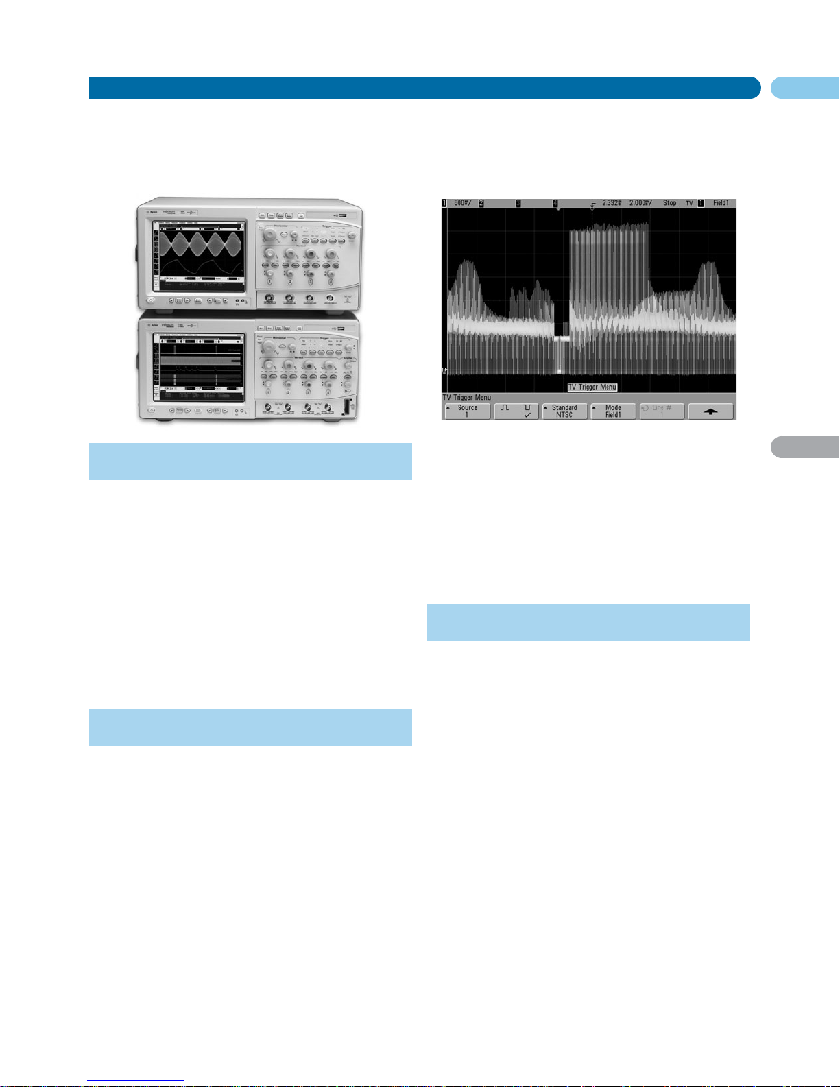
Triggering Edge, Pulse width, Pattern, TV (Composite and HDTV/EDTV), Duration
Dimensions 38.5 cm W x 18.8 cm H x 17.4 cm D (with handle)
Weight 4.1 kg
Accessories
Options
SEC Secure Environment Mode
E2690B Oscilloscope Tools (US/Can)
N5385B Oscilloscope Tools (Int’l)
N2916B Rackmount Kit for 6000 and 5000 Series Oscilloscopes
N2917B Transit Case for 6000 and 5000 Series Oscilloscopes
N2760A Soft Carrying Case for 5000 Series Oscilloscopes
Probes
10073C 10:1, 500 MHz Passive Probe (shipped with DSO605xA)
N2863A 10:1, 300 MHz Passive Probe (shipped with DSO501xA, 503xA)
10070C 1:1, 20 MHz Passive Probe
1130A 1.5 GHz InfiniiMax Differential Probe Amplifier (accessories sold
separately)
N2774A 50 MHz Current Probe, AC/DC (requires N2775A power supply)
1146A 100 kHz Current Probe, AC/DC
1147A 50 MHz Current Probe, AC/DC
10076A 100:1, 4 kV, 250 MHz High-voltage Probe
N2771A 1000:1, 15 kV, 50 MHz High-voltage Probe
1141A 200 MHz Differential Probe (requires 1142A power supply)
N2772A 600 V CAT III, 20 MHz Differential Probe (requires 9 V battery or
N2773A power supply)
Key Literature & Web link
Visit www.agilent.com/find/5000ct2 to download the following
additional information:
5000 Series Portable Oscilloscopes Brochure, p/n 5989-6385EN
5000 Series Portable Oscilloscopes Data Sheet, p/n 5989-6390EN
5000 and 6000 Series Probes and Accessories Data Sheet, p/n 5968-8153EN
Page 10

57
3
5000 Series
Oscilloscopes, 100 MHz to 500 MHz 5000 Series Oscilloscopes (cont.)
Oscilloscopes
Probe Scope Selection Guide
GP Portable High Performance Portable
DSO5000 DSO6000 MSO6000
Channel Channel 2 or 4 analog
Sample Rate Max Sample rate – 4 GSa/s
Display XGA resolution, up to 100,000 waveforms/sec and
256 levels of intensity scale
Accessories Extensive selection of probes and accessories
Connectivity Standard USB, LAN, GPIB connectivity, XGA out, LXI class C compliant
Bandwidth
100 MHz • • •
300 MHz • • •
500 MHz • • •
1 GHz ••
MegaZoom Deep Memory
1 Mpts – standard •
2 Mpts – standard •
8 Mpts – upgrade •
1
•
1
Triggering
Triggering (Edge, Pattern, Pulse, Width, TV, HDTV) • • •
I
2
C, SPI and USB serial bus triggering • •
CAN, LIN and FlexRay serial bus triggering •
1
•
1
Mixed signal trigger on both analog and digital content •
1
•
Digital Timing Channel
16 digital timing channels with mixed signal trigger and bus mode •
1
•
Xilinx and Altera FPGA dynamic probe application option •
1
•
1
Serial Decode
I2C/SPI/CAN/LIN/FlexRay serial bus decode •
1
•
1
Options
Battery option •
1
•
1
1
There is either an upgrade or for pay option available; advanced serial triggering and decode available on 4 or 4+16 – channel models only.
English URL www.agilent.com/find/products
Features
General Purpose High Performance
DSO5000 DSO6000 MSO6000
Channel Channel count 2 or 4 analog
Sample Rate Maximum sample rate 4 GSa/s
Display XGA display, 256 intensity levels, update rate 100,000 wps
Accessories Extensive selection of probes and accessories
Connectivity USB, LAN, GPIB connectivity, XGA out, LXI Class C compliant
Bandwidth
100 MHz • • •
300 MHz • • •
500 MHz • • •
1 GHz ••
MegaZoom Deep Memory
1 Mpts – standard •
2 Mpts – standard •
8 Mpts – upgrade •
1
•
1
Triggering
Triggering (Edge, Pattern, Pulse, Width, TV, HDTV) • • •
I
2
C, SPI and USB serial bus triggering • •
CAN, LIN and FlexRay serial bus triggering •
1
•
1
Mixed signal triggering across both analog and digital content •
1
•
Digital Timing Channel
16 digital timing channels with mixed signal triggering and bus display mode •
1
•
Xilinx and Altera FPGA dynamic probe application options •
1
•
1
Serial Decode
I2C/SPI/CAN/LIN/FlexRay serial bus decode •
1
•
1
Options
Battery option •
1
•
1
1
Upgrade or pay option available; advanced serial triggering and decode available on 4 channel models.
Page 11
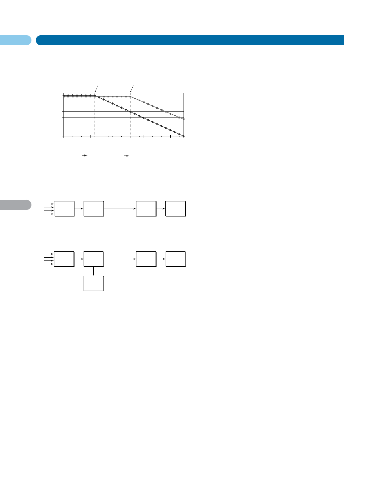
1 ns/div
10 ns/div
100 ns/div 1 s/div 10 s/div 100 s/div
1 ms/div 10 ms/div 100 ms/div 1 s/div
Time Base
10 GSa/s
1 GSa/s
100 MSa/s
10 MSa/s
1 MSa/s
1 kSa/s
10 kSa/s
100 kSa/s
Sample Rate
5 GSa/s, 10 k memory 4 GSa/s, 8 M memory
Inflection occurs
at 200 ns/div
Inflection occurs
at 100 s/div
58
DSO8000
MSO8000
MegaZoom Deep Memory
Oscilloscopes
English URL www.agilent.com/find/products
3
• Instant response to control signals – with up to 128 Mpts of
deep memory
• Zoom in quickly on critical signals
• Easily and quickly find infrequent and unpredictable events
A/D
Converter
Deep
Acquisition
Memory
Scope
Display
A/D
Converter
MegaZoom
Acquisition
Memory
Scope
CPU
Scope
Display
Deep
Acquisition
Memory
The entire waveform
record is sent to the CPU
creating a bottlenneck that
slows down operation and
can lead to missed signal
details.
MegaZoom optimizes the
sample rate for a given
sweep speed and sends
only the necessary
waveform data for a given
front panel setting,
resulting in waveform
update rates up to 25
times faster than other
deep-memory scopes for
a much more responsive
operating experience.
Scope
CPU
Conventional Deep-Memory Scope Architecture
MegaZoom Deep-Memory Scope Architecture
Scope memory affects sample rate.
Agilent MegaZoom delivers fast, responsive operation through a custom,
integrated circuit that optimizes data acquisition and processing.
Always On and Always Fast
With many of today’s designs containing a mix of signal types and
speeds, it’s often critical to capture and compare multiple cycles of
digital signals along with slower analog signals. But doing so often
requires an instrument that can deliver more resolution and
memory than a traditional DSO can provide. MegaZoom gives you
memory that is simultaneously fast and deep all the time, unlike
deep-memory options on alternative scopes. With Agilent oscilloscopes, you have up to 128 Mpts of MegaZoom deep memory,
enabling you to correlate high-speed digital control signals with
slower analog signals, capture infrequent events and then quickly
zoom in on the details to narrow in on problems. Unlike deep-memory
options on alternative scopes, Agilent MegaZoom is not a special
mode with sluggish response. It’s always on, always fast, and always
there to help you capture the most critical signals with maximized
sample rates.
Patented Technology
MegaZoom technology is based on a custom processor that controls
the flow of data into acquisition memory and rapid post-processing
for display and measurements. The MegaZoom processor operates
at the full speed of the scope’s A/D. Processing the data with
MegaZoom technology greatly reduces the amount of data
transferred to the scope’s CPU for post-processing. MegaZoom
substantially increases the waveform update rate and front-panel
responsiveness of Agilent’s deep memory scopes, making these
scopes better suited to working on today’s complex digital-based
designs. Responsiveness and waveform update rate slow down
dramatically on traditional deep memory oscilloscopes making
them difficult, sluggish and frustrating to use. Agilents oscilloscopes
feature patented MegaZoom technology that provides the fastest
waveform update rates – uncompromised. Agilent oscilloscopes also
feature best-in-class waveform viewing powered by MegaZoom technology.
Deep Memory Provides Sustained High Sample Rates
Besides bandwidth, one of the most fundamental specifications in a
digital storage oscilloscope (DSO) is its specified maximum sample
rate. However, a DSO’s sample rate is actually based on the scope's
time base setting. At the faster time base settings, all oscilloscopes
will capture waveforms using their specified maximum sample
rates. But as you adjust the time base setting to slower ranges in
order to capture longer waveforms, all scopes will automatically
reduce their sample rates because of their limited memory depths.
Deeper memory in an oscilloscope means that the scope can sustain
its maximum sample rate on more time base settings, enabling you
to see more details of your signals.
Page 12
59
MSO6000A
MSO8000A
Mixed Signal Oscilloscopes
Oscilloscopes
English URL www.agilent.com/find/products
3
• Mixed signal oscilloscopes – 16 digital channels time-correlated
with traditional scope analog channels
• Oscilloscope interface and ease of use with logic analyzer
insight, timing and measurements
• Precise analog measurements timed with exact digital content,
all in one box
Agilent pioneered the mixed signal oscilloscope in the mid 1990s
and has continued to modify and improve upon the original idea
since then. You can now choose from a large selection of bandwidths, memory depths and sample rates to meet your needs.
What is an MSO?
Increasing digital content brought about by the wide use of microcontrollers, DSPs, and microprocessors has added to the challenges
of design verification and debug. And the proliferation of low-cost
serial buses makes it more difficult to trigger on and interpret the
interaction of information as it flows through a system. To trace the
path between initial symptom and root cause of a problem with a
traditional 2- or 4-channel oscilloscope, you have to take multiple
acquisitions to capture all the signals of interest. Each acquisition
only gives you a narrow view of system behavior.
Agilent’s mixed signal oscilloscopes (MSOs) tightly correlate
2 or 4 analog channels with 16 logic timing channels. MSOs combine
all of the measurement capabilities of a digital storage oscilloscope
(DSO) with some of the measurement capabilities of a logic analyzer,
along with serial protocol analysis — in a single instrument. With an
MSO, you are able to see multiple time-aligned analog, parallel,
digital, and serially decoded waveforms on the same display.
MSOs allow you to trigger on any combination of analog and digital
signals – and on many popular serial bus protocols. You can do all of
this with a single, easy-to-use oscilloscope interface.
More Channels, More Memory, More Triggering
With the increasing digital content in today’s designs, it is often
difficult to capture enough channels simultaneously with a
traditional 2 or 4 channel scope. To further complicate matters, the
analog and digital sides are often operating at drastically different
speeds. The seamless integration of scope and logic timing channels
in the MSO gives you an instrument with unprecedented capabilities. With the MSO you can trigger on any combination of its scope
and logic channels with the low jitter performance you expect from
an oscilloscope. Now you can capture, display, and analyze a variety
of signals in one acquisition on one instrument screen, helping you
narrow in more quickly on tough design problems. With mixed
signal scopes, a 16-channel timing analyzer is seamlessly integrated
into a full-featured scope. It’s now easy to measure a combination of
signal types and speeds all at once, including slow analog slow
analog, fast digital, or baseband RF.
Page 13
60
3
DSO/
MSO6000
Series
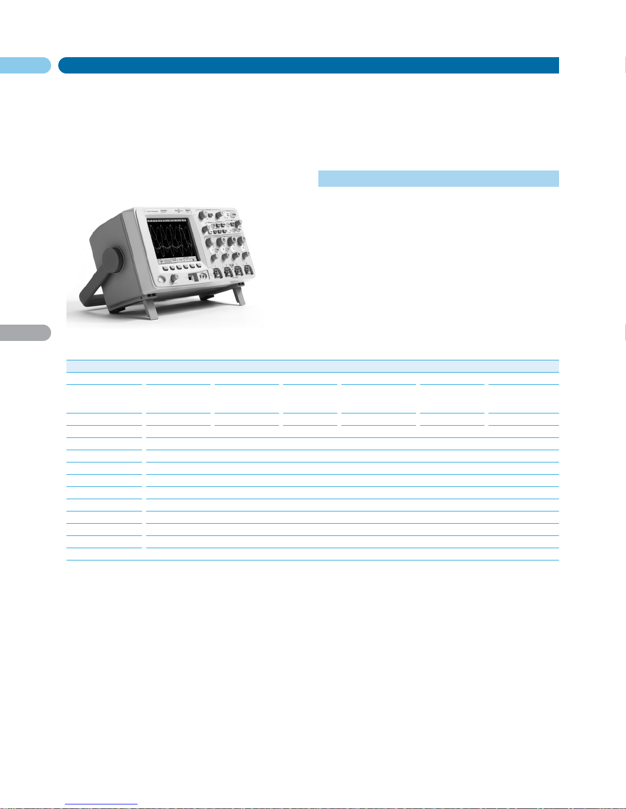
6000 Series Portable Oscilloscopes
Oscilloscopes
English URL www.agilent.com/find/products
Performance Packed at a Budget Price
These oscilloscopes are ideally suited for testing circuits that are
taking advantages of the use of onboard serial data. With bandwidths ranging from 100 MHz to 1 GHz, MegaZoom III deep memory
technology, advanced triggering, a high definition display, the look
and ease of use of an analog scope, and built-in help, Agilent’s 6000
Series oscilloscopes give you a view into your system performance
that is unmatched by any other portable oscilloscopes at a price that
fits within your budget.
Responsive Deep Memory
MegaZoom technology gives you higher sampling speeds where you
need them to observe the wide range of signals in your system,
rather than just the faster few sweep speeds. MegaZoom is available
at all times and does not require a special operating mode.
Measurement data are mapped into a high-resolution XGA color
display with 256 levels of intensity and 1000 points resolution, twice
the display resolution of other oscilloscopes.
Powerful Triggering
Because of increased digital content in today’s electronic circuits,
traditional level and slope scope triggering is no longer enough.
Agilent’s 6000 Series portable oscilloscopes offer a rich triggering
feature set that lets you easily isolate and analyze complex signals
and fault conditions. Triggers include:
• Pulse width • TV • I
2
C • SPI
• USB • LIN* • CAN* • FlexRay*
MegaZoom III Technology
The 6000 Series oscilloscopes are based on the third generation of
MegaZoom technology. This third generation of MegaZoom enhances
the responsiveness of this deep memory technology while maintaining its mode free operation. MegaZoom III provides:
• The most responsive deep memory available
• The highest definition color display available
• Fastest update rate, uncompromised
Available Applications and Options
The 6000 Series oscilloscopes are not only a powerful portable oscilloscope standard in their off the shelf configuration but they also
offer a selection of additional options to enhance debugging and
decoding of your specific application. From analog signal analysis of
vectors and Jitter to digital signal FPGA debugging to serial triggering a decoding of CAN, LIN and FlexRay the 6000 Series oscilloscopes can help you get your job done faster.
• Choose from Bandwidths ranging from 100 MHz to 1 GHz
• 100,000 Waveforms/sec update rate
• Up to 8 Mpts deep memory – Responsive MegaZoom III
deep memory
• Pick the model that best fits your budget
Agilent 6000 Series Oscilloscope Selection Guide
601xA 603xA 605xA 610xA
DSO6012A DSO6014A DSO6032A DSO6034A DSO6052A DSO6054A DSO6102A DSO6104A
MSO6012A MSO6014A MSO6032A MSO6034A MSO6052A MSO6054A MSO6102A MSO6104A
Bandwidth 100 MHz 300 MHz 500 MHz 1 GHz
Channels Scopes 2 or 2 + 16 4 or 4 + 16 2 or 2 + 16 4 or 4+16 2 or 2 + 16 4 or 4 + 16 2 or 2 + 16 4 or 4 + 16
Sample Rate 2 GSa/s 2 GSa/s 4 GSa/s 4 GSa/s
Maximum Memory 8 Mpts 8 Mpts 8 Mpts 8 Mpts
Standard Memory 2 Mpts 2 Mpts 2 Mpts 2 Mpts
Special Features All of the 6000 Series are supplied with MegaZoom III technology and MSO models incorporate the seamless integration of
16 logic timing channels. All models can be upgraded with additional memory at any time after purchase and all DSO models
can be upgraded to an MSO configuration in your lab as an after purchase product.
* available with purchase of option.
Page 14

61
3
DSO/
MSO6000
Series
6000 Series Portable Oscilloscopes (cont.)
Oscilloscopes
English URL www.agilent.com/find/products
Agilent Portable Oscilloscope Specifications
601xA 603xA 605xA 610xA
Channels 2 (DSO6012A) 2 (DSO6032A) 2 (DSO6052A) 2 (DSO6102A)
4 (DSO6014A) 4 (DSO6034A) 4 (DSO6054A) 4 (DSO6104A)
2 + 16 (MSO6012A) 2 + 16 (MSO6032A) 2 + 16 (MSO6052A) 2 + 16 (MSO6102A)
4 + 16 (MSO6014A) 4 + 16 (MSO6034A) 4 + 16 (MSO6054A) 4+ 16 (MSO6104A)
Scope Channels
Bandwidth 100 MHz 300 MHz 500 MHz 1 GHz
Max Sample Rate 2 GSa/s 2 GSa/s 4 GSa/s 4 GSa/s
Max Input 400 V dc + peak ac 400 V dc + peak ac 400 V dc + peak ac 400 V dc + peak ac
Resolution 8 bits 8 bits 8 bits 8 bits
High Resolution Mode 12 bits of resolution when ≥10 µs/div @ 4 GSa/s or ≥20 20 µs/div @ 2 GSa/s
Vertical Range 1 mV/div to 5 V/div 2 mV/div to 5 V/div 2 mV/div to 5 V/div 2 mV/div to 5 V/div
(1 MΩ input) (1 MΩ or 50 Ω input) (1 MΩ or 50 Ω input) (1 MΩ input),
2 mV/div to 1 V/div
(50 Ω input)
Max Memory 8 Mpts (optional) 8 Mpts (optional) 8 Mpts (optional) 8 Mpts (optional)
2 Mpts standard 2 Mpts standard 2 Mpts standard 2 Mpts standard
Time Base Range 5 nsec/div to 50/div 2 nsec/div to 50/div 1 nsec/div to 50/div 500 psec/div to 50/div
Peak Detection 1 ns peak detect 500 ps peak detect 250 ps peak detect 250 ps peak detect
Triggering
Source Internal selection of CH1, CH2, (CH3, CH4) Line and Ext
Modes Edge, Pattern, Pulse Width, TV, Sequence, Duration Nth edge and Serial Protocols of I
2
C, SPI, USB, CAN, LIN
(advanced CAN, LIN and FlexRay available through add-on optional applications)
Display
Type High Definition color LCD
Resolution XGA – 1024 horizontal x 768 vertical, 256 levels of intensity scale
Measurements
Automatic Peak-to-peak, maximum, minimum, average, amplitude, top, base, overshoot, undershoot,
RMS standard duration (AC RMS), frequency, period, +width, –width, duty cycle, time at max, time at min, phase, and delay
Counter Built-in 5 digit frequency counter on any channel, counts up to the scope’s bandwidth
The counter resolution can be increased to 8 digits with an external 10 MHz reference
Cursors Manually or automatically placed readout of Horizontal (X, deltaX, 1/deltaX) and Vertical (Y, deltaY)
Math Functions CH1 – CH2, 1*2, FFT, Differentiate, Integrate, sqrt
Storage
Type USB 1.1 ports on front and rear panels
Format Waveform images as BMP or PNG and waveform data as CSV, ASCII XY pair or binary
Connectivity USB 2.0 device, 2x USB 1.1 host, 10/100 Base T LAN, GPIB and Video output
Built-in Help Key specific help in 6 languages
Warranty 1 year, option increase to 5
Size 35.4 cm W x 18.8 cm H x 28.2 cm D (without handle)
Net Weight 4.9 kg (10.8 lbs)
Page 15

62
3
DSO/
MSO6000
Series
6000 Series Portable Oscilloscopes (cont.)
Oscilloscopes
English URL www.agilent.com/find/products
Memory and MSO Options
Option Number on New Option Number After Description 601xA/603xA 605xA/610xA
Units – Factory Installed Purchase – User Installed
8ML N2911A 8 Mpts half channel, •
4 Mpts each channel
8MH N2913A 8 Mpts half channel, •
4 Mpts each channel
Order MSO model N2914A MSO upgrade kit for •
DSO models (user installed)
Order MSO model N2915A MSO upgrade kit for •
DSO models (user installed)
Probe and Accessory Options
1146A 100 kHz/100 A Current Probe, AC/DC
N2772A 20 MHz Differential Probe (Requires N2773A power supply)
10070C 1:1 Passive Probe with ID
10076A 100:1, 4 kV, 250 MHz Probe with ID
N2771A 1000:1, 15 kV, 50 MHz High-voltage Probe
N2780A 2 MHz/500 A Current Probe, AC/DC (Requires N2779A
Power Supply)
N2781A 10 MHz/150 A Current Probe, AC/DC (Requires N2779A
Power Supply)
N2782A 50 MHz/30 A Current Probe, AC/DC (Requires N2779A
Power Supply)
N2783A 100 MHz/30 A Current Probe, AC/DC (Requires N2779A
Power Supply)
1147A 50 MHz Current Probe, AC/DC with AutoProbe Interface
1141A 200 MHz Differential Probe (Requires 1142A probe control and
power module)
1156A 1.5 GHz Active Probe with AutoProbe Interface
1130A 1.5 GHz InfiniiMax Differential Probe Amplifier with AutoProbe
Interface (Requires one or more InfiniiMax probe head – E2675A, E2668A,
E2669A)
1144A 800 MHz Active Probe (Requires 1142A power supply)
N2916B Rackmount Kit for 5000/6000 Series Scope
N2917B Transit Case for 5000/6000 Series Scope
1180CZ Testmobile Scope Cart
N2919A Testmobile Bracket for 1180CZ and 6000 Series Scope
N2918A Oscilloscope Evaluation Kit for 6000 Series Scope
Application Options
Digital Analysis
N5406A FPGA Dynamic Probing Xilinx
N5434A FPGA Dynamic Probing Altera
Serial Data Analysis
N5423A I
2
C/SPI Serial Decode Option (for 4/4 + 16 Ch models only)
N5424A AMS CAN + LIN Automotive Triggering and Decode (4/4 + 16 Ch
models only)
N5432A FlexRay Automotive Trigger + Decode FRS
Additional Options
BAT Battery option – operate scope without line power
SEC Secure environment mode option
Ordering Information
601xA 603xA 605xA 610xA
DSO6012A DSO6014A DSO6032A DSO6034A DSO6052A DSO6054A DSO6102A DSO6104A
MSO6012A MSO6014A MSO6032A MSO6034A MSO6052A MSO6054A MSO6102A MSO6104A
Bandwidth 100 MHz 300 MHz 500 MHz 1 GHz
Channels Scopes 2 analog or 2 analog or 2 analog or 4 analog or 2 analog or 4 analog or 2 analog or 4 analog or
2 analog + 2 analog + 2 analog + 4 analog + 2 analog + 4 analog + 2 analog + 4 analog +
16 digital 16 digital 16 digital 16 digital 16 digital 16 digital 16 digital 16 digital
Sample Rate 2 GSa/s 2 GSa/s 4 GSa/s 4 GSa/s
Maximum Memory 8 Mpts 8 Mpts 8 Mpts 8 Mpts
Standard Memory 2 Mpts 2 Mpts 2 Mpts 2 Mpts
Included Accessories 10:1 passive probe per scope (analog) channel, MSO includes a 54620-68701 (2 x 8) logic cable,
user guide, service manual, programmer’s manual, power cord, accessories storage,
front panel cover, one-year warranty, Agilent IO libraries version 14.2 CD
Page 16
63
3
6000L
6000L Series Low Profile Oscilloscopes
Oscilloscopes
• 4 channel scope in only 1U (43.6 mm space)
• Up to 1 GHz bandwidth, 4 GSa/s sample rates and 8 M memory
• Built in web browser for control
• Standard USB, LAN, GPIB interfaces and XGA out
• 100% compatible with 6000A Series portable oscilloscopes
• Optimized for automated and manufacturing test
• LXI class C compliant
English URL www.agilent.com/find/products
The Agilent 6014L Series digital storage oscilloscopes (DSOs) offer
four channels of measurements in a compact, rack-mountable 1Uhigh form factor, giving engineers a space-efficient way to integrate
oscilloscopes into their test systems.
Powerful Acquisition with MegaZoom III Deep Memory
Consistent with other Agilent oscilloscopes the deep memory that is
available in the 6000L Series Low Profile oscilloscope is based on
MegaZoom technology. 2 Mpt of MegaZoom deep memory comes
standard so you can capture long, non-repeating signals, while
maintaining high sample rates and good timing resolution.
Mixed Signal Analysis Option
If you work with both analog and digital circuitry, the Agilent 6000L
Series oscilloscope can help you see more signal activity in your
designs. You can upgrade the 6000L Series oscilloscope to a 4 scope +
16 logic timing channel mixed signal oscilloscope (MSO). Agilent’s
mixed signal oscilloscopes (MSOs) tightly correlate 4 analog channels with 16 logic timing channels. With an MSO, you are able to see
multiple time-aligned analog, parallel, digital, and serially decoded
waveforms on the same display.
Easy System Integration
Rack mount brackets and rack rails are standard with every unit
and because the units have side and rear air vents (no top or bottom
air vents) other instruments can be mounted directly above or below
them. There is built-in web server to provide remote access and control of the instrument via a standard Java-enabled web browser on
your computer. There is also a no-cost optional secure environment
mode that provides the highest level of security by ensuring that
internal memory is clear of all setup and trace settings. Because the
6000L Series Oscilloscope is LXI class C compliant and is 100% compatible with 6000A Series Oscilloscope it enables an easy transition
from development to manufacturing. Engineers can use the LXI
class C compliant 6000A Series portable oscilloscope during the
R&D phase, using the display, keypad and knobs. When your product
moves to manufacturing, you can use a system-optimized 6000L
Series LXI oscilloscope without a display.
Specifications
DSO6014L DSO6054L DSO6104L
Channels 4 scope channels (16 logic 4 scope channels (16 logic 4 scope channels (16 logic
channels available as option) channels available as option) channels available as option)
Scope Channels
Bandwidth 100 MHz 500 MHz 1 GHz
Max Sample Rate 2 GSa/s 4 GSa/s 4 GSa/s
Max Input 400 V dc + peak ac 400 V dc + peak ac 400 V dc + peak ac
Vertical Resolution 8 bits 8 bits 8 bits
High Resolution Mode <100 nsec/div, 8 bits <100 nsec/div, 8 bits <100 nsec/div, 8 bits
(Time Base & Bits of Resolution) 500 nsec/div, 9 bits 500 nsec/div, 9 bits 500 nsec/div, 9 bits
2 µsec/div, 10 bits 2 µsec/div, 10 bits 2 µsec/div, 10 bits
10 µsec/div, 11 bits 10 µsec/div, 11 bits 10 µsec/div, 11 bits
≥50 µsec/div, 12 bits ≥50 µsec/div, 12 bits ≥50 µsec/div, 12 bits
Standard Memory 2 Mpts on 2 channels, 1 Mpts on 4 channels
Time Base Range 5 nsec/div to 50 sec/div 1 nsec/div to 50 sec/div 500 psec/div to 50 sec/div
Peak Detection 1 ns peak detect 250 ps peak detect 250 ps detect
Triggering
Source DSO6xx4L: Ch 1, 2, 3, 4, line, ext and D0 – D15 for MSO enabled DSO
Modes Edge, Pattern, Pulse Width, TV, Sequence, Duration, Nth edge burst and Serial Protocols of I
2
C,
SPI, USB (CAN, LIN and FlexRay available through add-on optional applications)
Display ———
Measurements
Automatic Peak-to-peak, maximum, minimum, average, amplitude, top, base, overshoot,
preshoot, RMS, standard deviation (AC RMS), frequency, period, +width, –width, duty cycle,
time at max, time at min, time at max, phase, and delay
Counter Built-in 5 digit frequency counter on any channel, counts up to the scope’s bandwidth
The counter resolution can be increased to 8 digits with an external 10 MHz reference
Math Functions CH1 – CH2, CH1 + CH2, 1*2, FFT, Differentiate, Integrate
Connectivity USB 2.0 device, 2 x USB 1.1 host, 10/100 Base T LAN, GPIB and XGA Video output
Warranty 1 year, option increase to 3
Size 43.5 cm W x 27 cm D x 4.2 cm H (without brackets)
Net Weight Net: 2.45 kg (5.4 lbs.)
Shipping: 6.2 kg (13.6 lbs.)
Page 17

64
3
6000L
6000L Series Low Profile Oscilloscopes (cont.)
Oscilloscopes
Key Literature & Web link
Agilent Technologies 6000L Low Profile Oscilloscopes Data Sheet,
p/n 5989-5470EN
Agilent Oscilloscope Probes and Accessories Selection Guide,
p/n 5989-6162EN
Agilent 6000 Series Oscilloscopes Data Sheet, p/n 5989-2000EN/EUS
Agilent 5000 and 6000 Series Oscilloscope Probes and Accessories
Data Sheet, p/n 5968-8153EN
Option SEC N5427A Secure Environment Mode Option Data Sheet,
p/n 5968-5558EN
Next-Generation Test Systems Application Note, p/n 5989-2802EN
LXI: Going Beyond GPIB, PXI and VXI Application Note, p/n 5989-4371EN
Optimizing Test Systems for Highest Throughput Lowest Cost and Ease of
Integration with LXI Instruments Application Note, p/n 5989-4886EN
Open the Door to Simpler System Creation Brochure, p/n 5989-2042EN
Ordering Information
6000L Series Low-profile Oscilloscopes
DSO6014L DSO6034L DSO6104L
Bandwidth 100 MHz 500 MHz 1 GHz
Channels Scopes 4 scope 4 scope 4 scope
Sample Rate 2 GSa/s 4 GSa/s 4 GSa/s
Standard Memory 2 Mpts 2 Mpts 2 Mpts
The above models include: user’s guide, service guide, programmers
guide, power code, 10:1 divider passive probe per scope channel, Agilent
IO Libraries Suite 14.2, 1 year warranty, GPIB extender, LAN crossover
cable, rack mount hardware
Standard Probes Included
Passive Probes Logic Cable Kit – Comes
with MSO Upgrade Kit
DSO6014L 10074C 10:1 passive probe 54826-68701 MSO logic
(qty 4) cable kit (qty 1)
DSO6034L 10073C 10:1 passive probe 54826-68701 MSO logic
(qty 4) cable kit (qty 1)
DSO6104L 10073C 10:1 passive probe 54826-68701 MSO logic
(qty 4) cable kit (qty 1)
Available Options
DSO6014L DSO6054L/
DSO6104L
N2914A MSO upgrade kit for •
DSO6014L
N2915A MSO upgrade kit for •
DSO6054L/DSO6104L
-SEC Secure environment mode • •
(factory installed option)
N5423A LSS I2C/SPI decode option • •
N5424A AMS CAN, LIN and FlexRay • •
decode option
N5432/FRS Flex Ray decode option • •
English URL www.agilent.com/find/products
Probe Options
10070C 1:1, 1 MΩ Passive Probe*
1147A 50 MHz, 50 A AC/DC Current Probe
10076A 100:1, 4 kV, 250 MHz High Voltage Probe
1144A 800 MHz Active Probe – order 1142A Power Supply
1145A 2 Channel 750 MHz Active Probe – order 1142A Power Supply
1156A 1.5 GHz Active Probe with AutoProbe Interface (power supply not
required)
1130A 1.5 GHz InfiniiMax Probe Amplifier – no probe heads included**
Memory Upgrade
8ML – 100 MHz
8MH – 500 MHz + 1 GHz
* fine-pitch and IC probing kits available (10072, 10075A).
** for a complete probing solution, also order a connectivity kit or individual probe head(s)
(E2675A, E2668A, E2669A).
Page 18
65
3
8000 Series
Infiniium 8000 Series Oscilloscopes
Oscilloscopes
• Choose 600 MHz or 1 GHz bandwidth
• 4 GSa/s sample rate
• Up to 128 Mpts memory
• Open Windows XP Pro based with touch screen drag and drop
measurements
• Extensive application software suite
• MegaZoom Technology powered deep memory, display and
viewing system
• Unrivaled InfiniiMax active probes and accessories
English URL www.agilent.com/find/products
Agilent’s Infiniium oscilloscopes combine ease of use and the right
specifications with a broad feature set to help you get your job done
faster. If you are tired of spending 80 percent of your lab time fighting your instrumentation and only 20 percent making meaningful
measurements, Infiniium is the scope for you.
Industry-Leading MegaZoom Deep Memory
MegaZoom is Agilent’s unique, patented technology that gives you
the advantages of deep memory without the usual drawbacks.
MegaZoom deep memory lets you capture a full cycle of your sys-
tem’s operation and responsively zoom in on specific areas of interest. MegaZoom deep memory captures long records with fast
waveform updates, minimizing dead-time between acquisitions.
Signal Integrity
If you are concerned about accurate reproduction of your signals as
they appear on your device under test, you need the best end-to-end
measurement system starting at the probe tip. The 1156A 1.5 GHz
single-ended active probe is uniquely designed for a flat frequency
response over the entire probe bandwidth, eliminating the distortion and frequency-dependent loading effects that are present
in probes that have an in-band resonance. The InfiniiMax 1130A
1.5 GHz differential/single-ended active probe system builds on this
technology by providing a variety of flexible probe heads to gain
access to the most difficult to access test points.
Open Windows XP Pro Interface
Infiniium’s intuitive Windows-based graphical user interface (GUI),
coupled with its analog-like control knobs, puts the scopes’ powerful
measurements, waveform math functions, advanced analysis capabilities, and triggering at your fingertips. Infiniium’s open Windows
XP Professional architecture is a robust environment for installing
third-party or custom analysis software applications inside the
oscilloscope for the most expansive one-box test solution. The open
architecture enables all the standard PC connectivity you are familiar with, making it easy to share your work and communicate your
results. Infiniium features an email-ontrigger function that will send
an email with date and time stamp in addition to an attached screen
image to any email account in the world once a trigger event occurs.
Use a Java™ – Venabled Web browser to share access with team
members working remotely from their very own PC.
Available Add On Application-specific Solutions
The PC platform of the Infiniium enables it to be the perfect place to
run your software application right on the instrument. Agilent has
created a wide selection of applications, available as add on options
(either before or after purchase) to help take advantage of that PC
power and get you further down the road to your end product.
Agilent Infiniium 8000 Series Selection Guide
8064A 8104A
DSO8064A MSO8064A DSO8104A MSO8104A
Bandwidth 600 MHz 1 GHz
Channels Scopes 4 analog 4 analog + 4 analog 4 analog +
16 digital 16 digital
logic logic
Sample Rate 4 GSa/s 4 GSa/s
Maximum Memory 128 Mpts 128 Mpts
Standard Memory 8 Mpts 8 Mpts
Special Features Advanced measurement suite with touch screen
drag-and-drop capability. Extensive built-in waveform
analysis with histograms, mask testing, and
measurement statistics for full signal characterization.
Segmented memory acquisition mode for efficient
capture of bursting signals. Extensive Application
suite available
Page 19

66
3
8000 Series
Infiniium 8000 Series Oscilloscopes (cont.)
Oscilloscopes
Specifications
DSO8064A MSO8064A DSO8104A MSO8104A
Bandwidth 600 MHz 600 MHz 1 GHz 1 GHz
Channels Scopes 4 analog 4 analog + 16 digital logic 4 analog 4 analog + 16 digital logic
Scope Channels
Maximum Sample Rate 4 GSa/s 4 GSa/s 4 GSa/s 4 GSa/s
Maximum Memory 128 Mpts 128 Mpts 128 Mpts 128 Mpts
Standard Memory 8 Mpts 8 Mpts 8 Mpts 8 Mpts
Sampling Modes Real time, equivalent time, peak detect, high resolution, averaging and segmented
Max input, High Z 150 V RMS or dc, CAT I; ±250 V (dc + ac) in AC coupling
Max input, 50 Ohms 5 V RMS, CAT I
Vertical Resolution 8 bits, >12 bits with averaging or high resolution modes
Dynamic Range ±8 div from center screen (1 MΩ) and ±12 div from center screen (50 Ω)
Logic Channels (MSO models only)
Maximum Sample Rate 1 GSa/s 1 GSa/s 1 GSa/s 1 GSa/s
Maximum Memory 32 Mpts 32 Mpts 32 Mpts 32 Mpts
Input Level 500 mV p-p minimum, ±40 V Maximum
Threshold ±8 V in 10 mV increments ±8 V in 10 mV increments ±8 V in 10 mV increments ±8 V in 10 mV increments
Glitch Detection 2.5 ns minimum 2.5 ns minimum 2.5 ns minimum 2.5 ns minimum
Timebase
Range 500 ps/div to 20 s/div 500 ps/div to 20 s/div 200 ps/div to 20 s/div 200 ps/div to 20 s/div
Resolution 4 ps 4 ps 4 ps 4 ps
Accuracy 15 ppm (±0.0015%) 15 ppm (±0.0015%) 15 ppm (±0.0015%) 15 ppm (±0.0015%)
Jitter Measurement Floor
– time internal error 7 ps rms 7 ps rms 5ps rms 5ps rms
– period jitter 10 ps rms 10 ps rms 7 ps rms 7 ps rms
– N-cycle, Cycle-Cycle Jitter 15 ps rms 15 ps rms 11 ps rms 11 ps rms
Triggering
Source All Channels (Scope Channels 1 – 4 and Logic Channels D0 – D15) & External
Modes Edge, glitch, line, pattern, state, delay by time, delay by events, TV & violation triggers
(pulse width, setup/hold, and transition)
Jitter 8 ps ± 0.05 ppm x |delay setting| rms
Display 8.4 inch diagonal color TFT-LCD; Maximum waveforms/second >8,800
Waveform Measurements
Voltage Peak-to-Peak, Minimum, Maximum, Average, RMS, Amplitude, Base, Top, Overshoot, Preshoot,
Upper, Middle, Lower, Area
Time Period, Frequency, Positive Width, Negative Width, Duty Cycle, Delta Time, Rise Time, Fall Time,
Tmin, Tmax, Channel-to-Channel Phase
Frequency Domain FFT Frequency, FFT Magnitude, FFT Delta Frequency, FFT Delta Magnitude, FFT Phase
Eye Pattern Eye Height, Eye Width, Jitter, Crossing %, Q-Factor, Duty Cycle Distortion, Statistics, Histograms, Mask Testing
Jitter clock (scope only) Cycle-cycle jitter, N-cycle jitter, cycle-cycle +width, cycle-cycle –width, cycle-cycle duty
cycle (all with EZJIT)
Jitter data (scope only) Time interval error (TIE), data rate, unit interval (all with EZJIT)
Math Functions Four functions f1 – f4. Select from add, average, common mode, differentiate, divide, FFT magnitude, FFT phase,
high pass filter, integrate, invert, low pass filter, magnify, min, max, multiply, smoothing, subtract, versus
Drives ≥40 GB internal hard drive (optional removable hard drive) CD-ROM drive on rear panel
IO ports LAN, GPIB, RS-232, Parallel, PS/2, USB 2.0,video output, auxiliary output, TTL trigger output
Warranty 1 year standard, option increase to 3 years
Size 216 mm H x 437 mm W x 440 mm D (8.5 in x 17.19 in x 17.34 in)
Net Weight Net: 13.4 kg (29.5 lbs.); Shipping: 16.4 kg (36.1 lbs.)
English URL www.agilent.com/find/products
Page 20

67
3
8000 Series
Infiniium 8000 Series Oscilloscopes (cont.)
Oscilloscopes
Accessories
Extensive Application Software
The Agilent 8000 Series Infiniium Oscilloscope offers a broad
portfolio of add-on applications that enable you to customize your
oscilloscope. Agilent engineers have worked with industry experts
to create software for the oscilloscope that will offer application
specific insight and ultimately save you time. These options are
available as add on options either before or after purchase.
English URL www.agilent.com/find/products
Application Area Application Name Product Number/Option Number Publication Number Description
Digital Debug FPGA dynamic N5397A 5989-1848EN • Quickly and easily access your
probing Xilinx FPGA troubleshooting pins
• Save time with easy signal identification
• Enable measurement of a wide range of
signals on our design without
reprogramming your FPGA
FPGA dynamic N5433A 5989-5940EN • Quickly and easily access your
probing Altera FPGA troubleshooting pins
• Save time with easy signal identification
• Enable measurement of a wide range of
signals on our design without
reprogramming your FPGA
Serial Data Analysis Low-speed serial N5391A 5989-1250EN • Save time with automatic decode
data analysis for • Easily sort through data with click and zoom
I
2
c or SPI serial • Find the data you are looking for quickly
communication buses with search functions for a particular packet
CAN serial data N5402A 5989-3632EN • View both protocol and physical layer
analysis software information directly on the Infiniium
• Save time with automatic decode
• Easily sort through data with click and zoom
High-speed serial N5384A 5989-0108EN • Effectively validate signal integrity
data analysis • Recover embedded clock signals then
software display and make TIE Jitter measurements
relative to them
• Build and recover eye diagrams
Jitter Analysis EZJIT Jitter Analysis E2681A 5989-0109EN • Access the measurements you need the
most for Jitter; cycle-cycle jitter, N-cycle jitter,
period jitter, time interval error, setup and
hold time, measurement histograms,
measurement trending and jitter spectrum
• Save time with set-up wizard
Compliance Testing Ethernet performance N5392A 5989-1527EN • Quickly and easily verify and debug
validation and N5395B (Ethernet test fixture) 1000Base-T, 1000base-TX,
compliance software N5396A (Gigabit Ethernet Jitter 10base-T Ethernet designs
test cable) • Automatically execute Ethernet
physical-layer electrical tests
USB 2.0 performance N5416A 5989-4044EN • Fast and reliable way to verify SUB
validation and E2646A (SQiDD test fixture) electrical specification compliance for
compliance software USB 2.0 devices
• Execute MATLAB USB-IF scripts inside
the Infiniium
Vector Signal VSA software 89601A 5989-0947EN • Enables flexible signal analysis and
Analysis for Infiniium demodulation up to 1 GHz bandwidth
for troubleshooting wideband modulated
signals in radar and communications
applications
Page 21

68
3
8000 Series
Infiniium 8000 Series Oscilloscopes (cont.)
Oscilloscopes
Accessories
Application Area Application Name Product Number/Option Number Publication Number Description
Usability My Infiniium E2699A 5988-9934EN • Launch your application directly from
Enhancements the oscilloscope front panel
Communication E2652A 5989-0372EN • Ensure your design meets industry
Mast Test Kit communication standards. Comes with
a set of electrical communication adapters
to ensure convenient, reliable, and accurate
connections to your device under test
VoiceControl E2682A • Speak into the collar-mounted microphone
software to operate your Infiniium’s front-panel
controls without using your hands
Logic Analyzer/ E5805A • Easily make time correlated measurements
Oscilloscope time between an Agilent 16900 Series logic
correlation analysis system or Agilent 1680/90 Series
benchtop logic analyzer and an Infiniium
oscilloscope without a correlation fixture
User Defined N5430A 5989-5632EN • Develop your own custom math functions
Function or filters using MATLAB
®
and its Signal
Processing Toolbox and display them on
your oscilloscope along side the other
standard functions*
Infiniiscan N5415A 5989-4605EN • Quickly and easily identify signal integrity
issues with InfiniiScan. Isolate anomalous
signal behavior with application scans
through thousand of acquired waveforms.
Capture anomalies that hardware-based
solutions can’t find
* User must purchase MATLAB®from The MathWorks separately.
Active Probes
Probing high-frequency signals becomes more challenging as the variety
of test points and the frequencies of the signals continue to grow. Probes
need to be lightweight, small, affordable, and offer the accessories and
probe tips you require to get your job done easily. For high-speed differential signal measurements, the 1130A InfiniiMax differential probe amp,
with its variety of probe heads, is a perfect compliment to the Infiniium
8000 Series oscilloscopes. Its 1.5 GHz bandwidth, extremely low input
capacitance, high common mode rejection and the patented resistor
probe tip technology provide ultra-low loading of the DUT and superior
signal fidelity. The 1156A active probe is a small, low-mass, active probe
also with 1.5 GHz bandwidth. The probe offers a flat frequency response
across the entire probe bandwidth, even with a variety of accessories
attached, giving you accurate insight into your high-speed measurement.
Agilent offers a variety of probe tips to help you probe any test point.
Model Probe System Single-ended/
Bandwidth Bandwidth Differential
1156A 1.5 GHz 1 GHz with MSO8104A and DSO8104A single-ended
600 MHz with MSO8064A and DSO8064A
1130A 1.5 GHz 1 GHz with MSO8104A and DSO8104A both
1,2
1
Depending on probe head used.
2
For a complete probing solution, also order a connectivity kit or individual probe head(s).
Key Literature & Web Link
Infiniium 8000 Series Oscilloscopes Data Sheet, p/n 5989-4271EN
Infiniium Probes, Accessories and Options Data Sheet, p/n 5989-7141EN
Agilent Oscilloscope Probes and Accessories Selection Guide,
p/n 5989-6162EN
Agilent 8000 Series Oscilloscopes Brochure, p/n 5989-5806EN
Ordering Information
Standard Probes Included
DSO8064A 10073C 10:1 Passive Probe (qty 4)
MSO8064A 10073C 10:1 Passive Probe (qty 4), 54826-68701 MSO Logic
Cable Kit (qty 1)
DSO8104A 10073C 10:1 Passive Probe (qty 4)
MSO8104A 10073C 10:1 Passive Probe (qty 4), 54826-68701 MSO Logic
Cable Kit (qty 1)
Memory Options
N5407A-080 16 Mpts on 2 Channels, 8 Mpts on 4 Channels
N5407A-160 32 Mpts on 2 Channels, 16 Mpts on 4 Channels
N5407A-320 64 Mpts on 2 Channels, 32 Mpts on 4 Channels
N5407A-640 128 Mpts on 2 Channels, 64 Mpts on 4 Channels
Probe and Accessory Options
1146A 100 kHz/100 A Current Probe, AC/DC
N2772A 20 MHz Differential Probe (Requires N2773A power supply)
10070C 1:1 Passive Probe with ID
10076A 100:1, 4 kV, 250 MHz Probe with ID
N2771A 1000:1, 15 kV, 50 MHz High-voltage Probe
N2780A 2 MHz/500 A Current Probe, AC/DC (Requires N2779A Power Supply)
N2781A 10 MHz/150 A Current Probe, AC/DC (Requires N2779A
Power Supply)
N2782A 50 MHz/30 A Current Probe, AC/DC (Requires N2779A
Power Supply)
N2783A 100 MHz/30 A Current Probe, AC/DC (Requires N2779A
Power Supply)
1147A 50 MHz Current Probe, AC/DC with AutoProbe Interface
1141A 200 MHz Differential Probe (Requires 1142A probe control and
power module)
1153A 200 MHz Differential Probe
1155A 750 MHz, 2-channel, Low-mass Active Probe
1156A 1.5 GHz Active Probe with AutoProbe Interface
1130A 1.5 GHz InfiniiMax Differential Probe Amplifier with AutoProbe
Interface (Requires one or more InfiniiMax probe head – E2675A, E2668A,
E2669A)
1144A 800 MHz Active Probe (Requires 1142A power supply)
N2916B Rackmount Kit for 5000/6000 Series Scope
N2917B Transit Case for 5000/6000 Series Scope
1180CZ Testmobile Scope Cart
N2919A Testmobile Bracket for 1180CZ and 6000 Series Scope
N2918A Oscilloscope Evaluation Kit for 6000 Series Scope
E5396A Half-size (17 channel) Soft Touch Connectorless Logic Probe for
MSO Models
Miscellaneous Options
017 (factory installed) ≥40 GB Removable Hard Disk Drive.
Replaces ≥40 GB Internal Hard Disk with a ≥40 GB Removable Hard Disk.
Order the N5422A for Additional Hard Disk Drive Cartridges that contain
the Full Windows Operating System and Oscilloscope Application.
1181BZ Testmobile System Cart
1184A Testmobile with Keyboard/Mouse Tray and Drawer for Accessories
E2609B Rackmount Kit
A6J ANSI Z540-compliant Calibration
R-51B-001-3C 1 Year Return-to-Agilent warranty extended to 3 Years
Page 22
69
80000 Series
English URL www.agilent.com/find/products
3
High-Performance Infiniium Oscilloscopes
Oscilloscopes
Superior Signal Integrity and Probing for
Your Application
The superior signal integrity, probing and application software
selection of Agilent Technologies’ Infiniium DSO/DSA80000B Series
and InfiniiMax II probing system will lead to improved measurements and increased design margins.
The signal integrity advantages of Agilent’s Infiniium 80000B
Series Scopes and InfiniiMax Probing System include the industry’s
lowest noise floor, lowest jitter measurement f loor, lowest trigger jitter and flattest frequency response. These foundational capabilities
are crucial for achieving accurate and repeatable measurements.
These superior signal integrity capabilities come from Agilent’s
RFdesign experience, proprietary packaging technologies and
unique CMOS ADC architecture. Superior signal integrity maximizes engineer’s design margins by not wasting any measurement
accuracy due to the poor noise, jitter or frequency response of the
scope or probing system.
Agilent Infiniium DSO/DSA80000B Series Oscilloscopes Selection Guide
DSO/DSA81304B DSO/DSA81204B DSO/DSA81004B DSO/DSA80804B DSO/DSA80604B DSO/DSA80404B DSO/DSA80304B DSO/DSA80204B
Bandwidth 13 GHz 12 GHz 10 GHz 8 GHz 6 GHz 4 GHz 3 GHz 2 GHz
Channels 44444444
Sampling Rate 20 – 40 GSa/s 20 – 40 GSa/s 20 – 40 GSa/s 20 – 40 GSa/s 20 – 40 GSa/s 20 – 40 GSa/s 20 – 40 GSa/s 20 – 40 GSa/s
Standard Memory 0.25 – 0.5 M 0.25 – 0.5 M 0.25 – 0.5 M 0.25 – 0.5 M 0.25 – 0.5 M 0.25 – 0.5 M 0.25 – 0.5 M 0.25 – 0.5 M
Max Memory 1 – 2 M (64 M at 4 GSa/s)
(Option 001, standard
on DSA Models)
Rise Time/Fall Time
(20 – 80%) 23 ps 25 ps 30 ps 38 ps 48 ps 91 ps 108 ps 152 ps
(10 – 90%) 33 ps 36 ps 42 ps 54 ps 70 ps 105 ps 108 ps 152 ps
Noise 3.3 mV 2.7 mV 2.3 mV 2.1 mV 1.8 mV 1.4 mV 1.2 mV 1.0 mV
(rms at 100 mV/div)
Hardware Sensitivity 5 mV/div to 5 mV/div to 5 mV/div to 5 mV/div to 5 mV/div to 5 mV/div to 5 mV/div to 5 mV/div to
(SW Expansion to 1 V/div 1 V/div 1 V/div 1 V/div 1 V/div 1 V/div 1 V/div 1 V/div
1 mV/div)
Timebase Range 5 ps/div to 5 ps/div to 5 ps/div to 5 ps/div to 5 ps/div to 5 ps/div to 5 ps/div to 5 ps/div to
20 s/div 20 s/div 20 s/div 20 s/div 20 s/div 20 s/div 20 s/div 20 s/div
Popular Scope EZJIT Jitter Analysis Software (Option 002, Standard on DSA models)
Options High Speed Serial Data Analysis Software (Option 003, Standard on DSA models)
EZJIT Plus Advanced Jitter Analysis Software (Option 004, Standard on DSA models)
Noise Reduction Software (Option 005, Standard on DSO/DSA81304B)
My Infiniium Customization Software (Option 006)
InfiniiScan Event Identification Software (Option 009)
User Defined Function Software (Option 010)
• Industry’s lowest noise floor for both oscilloscopes and probes
• Industry’s lowest jitter measurement floor
• Industry’s lowest trigger jitter – less than 500 fs rms
• Industry’s flattest frequency response
• Industry’s only bandwidth upgradeable series from 2 GHz to 13 GHz
• Industry’s largest selection of application software packages
• Industry’s only full bandwidth economical lead-free solder-in
probe solution
• Industry’s first software event finder “InfiniiScan” (option)
• Now LXI functional class C compliant
Page 23

70
80000 Series
English URL www.agilent.com/find/products
3
High-Performance Infiniium Oscilloscopes (cont.)
Oscilloscopes
Infiniimax Probing System – Probe Amplifiers
1169A 1168A 1134A 1132A 1131A 1130A
BW Spec 12 – 13 GHz 10 GHz 7 GHz 5 GHz 3.5 GHz 1.5 GHz
Recommended DSO81304B DSO81004B DSO80604B DSO80404B DSO80304B DSO80204B
Oscilloscope DSO81204B DSO80804B DSO80204B
Attenuation 3.45:1 3.45:1 10:1 10:1 10:1 10:1
Dynamic Range 3.3 Vp-p 3.3 Vp-p 5 Vp-p 5 Vp-p 5 Vp-p 5 Vp-p
Noise Referred 2.5 mV rms 2.5 mV rms 3.0 mV rms 3.0 mV rms 3.0 mV rms 3.0 mV rms
to Input
Infiniimax Probing Systems – Probe Heads
N5380A N5381A N5382A N5425A/ E2675A E2676A E2677A E2678A E2679A E2695A
N5426A
Typ BW 13 GHz 13 GHz 13 GHz 13 GHz 6 GHz 6 GHz 12 GHz 12 GHz 6 GHz 8 GHz
Description Hi-BW Hi-BW Hi-BW Hi-BW Differential Single-Ended Differential Differential Single-Ended Differential
Differential Differential Differential Differential Browser Browser Solder-in Socket Solder-in SMA
SMA Solder-in Browser ZIF Solder-in
Diff Capacitance — 0.21 pF 0.21 pF 0.33 pF 0.32 pF 0.67 pF 0.27 pF 0.34 pF 0.50 pF —
Infiniimax Probing Systems – Connectivity Kits and Misc
E2669A E2668A E2697A
Description Differential Kit Single-Ended Kit 1 Mohm High Impedance Adapter
Includes E2675A, E2677A x4, E2678A E2676A, E2679A, E2678A 500 MHz Passive Probe
InfiniiMax Extreme Temperature Cable Extension
A SMP microwave extension cable from Gore (W. L. Gore & Associates,
Inc.) is available for extending the reach of InfiniiMax probes into tight
environments or into test chambers (Part number PRP042105-01).
Please contact Gore at 1-800-311-3060 or look up international
contacts at www.gore.com
Operating Temperature Range: 0 to 105°C
Page 24
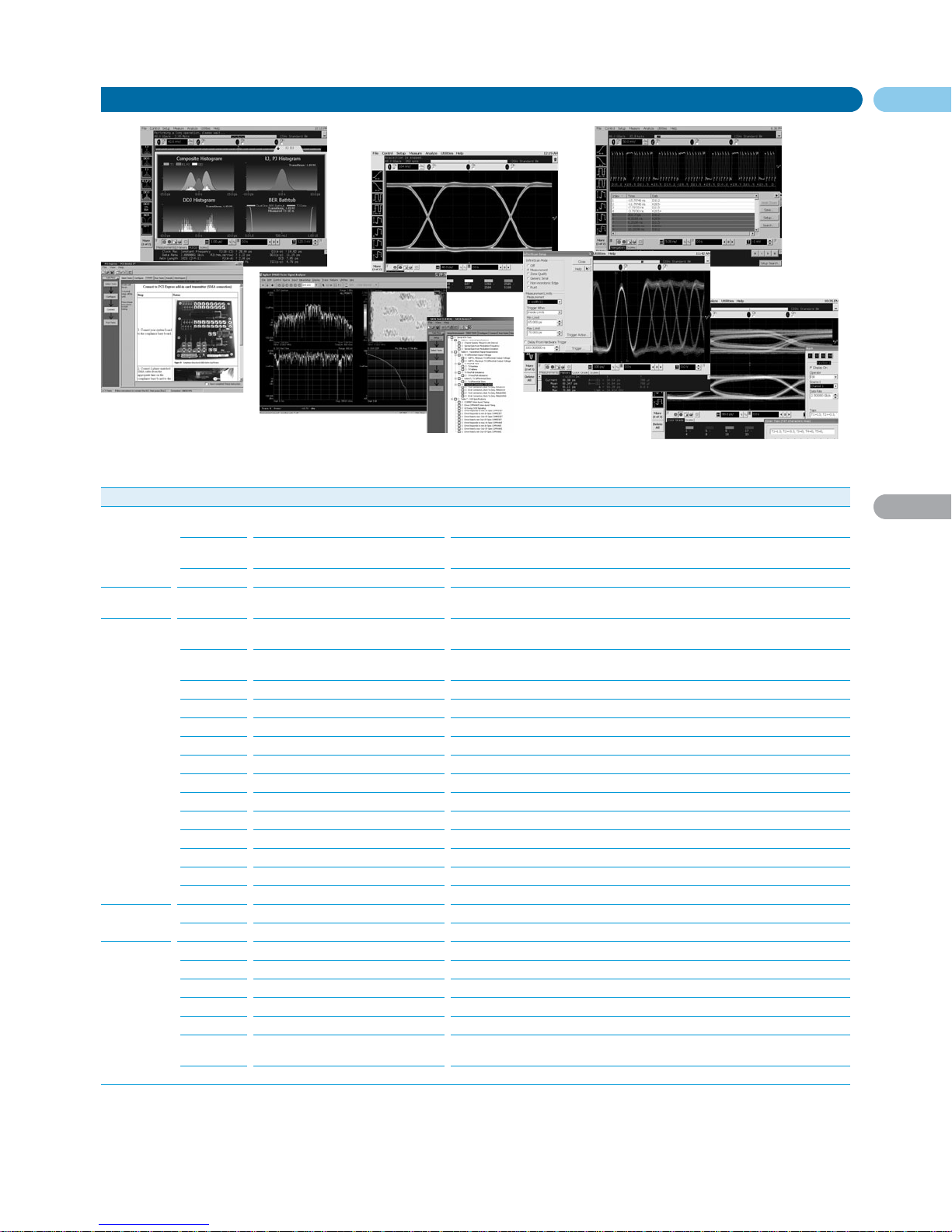
71
80000 Series
English URL www.agilent.com/find/products
3
High-Performance Infiniium Oscilloscopes (cont.)
Oscilloscopes
Infiniium Software Applications
Area Part Number Name Description
Jitter E2681A EZJIT Jitter Analysis (Option 002) Wizard based – measurements, histograms, measurement trending,
jitter frequency spectrum
N5400A EZJIT Plus Jitter Analysis (Option 004) Adds jitter separation into components and bit error rate projections.
Same UI as 86100C Infiniium DCA-J
E2690B M1 Jitter Analysis (3rd Party) Most advanced and flexible jitter analysis package. Supports offline analysis as well.
Serial E2688A High Speed SDA Serial Data Analysis Wizard based – clock recovery, mask testing, real-time eyes with unfolding,
Analysis (Option 003) 8b/10b decode, listing, and trigger
Compliance N5393A PCI Express 1.0/1.1 Compliance Wizard based framework – test selection, configuration, connection, execution,
results. Requires SDA
N5392A Ethernet Compliance Wizard based framework – test selection, configuration, connection, execution, results
(10/100BaseTX, Gigabit)
N5394A DVI Compliance Wizard based framework – test selection, configuration, connection, execution, results
N5399A HDMI Compliance Wizard based framework solution, supporting the latest HDMI 1.3. Listed in CTS 1.3.
N5409A Fully Buffered DIMM Compliance Wizard based framework solution supporting FBD1/AMB1
N5410A Fiber Channel Compliance Wizard based framework. Industry’s only Fiber Channel compliance solution
N5411A Serial ATA Compliance Wizard based framework, supporting both SATA gen 1 and gen 2
N5412A SAS Compliance Wizard based framework for Serial Attached SCSI
N5413A DDR2 Full Compliance Wizard based framework solution for both clock and data characterization
N5416A USB 2.0 Compliance Wizard based framework based on USB-IF developed MATLAB script
N5431A XAUI Compliance Wizard based framework for Industry’s only XAUI compliance solution
N5402A CAN Serial Data Analysis For CAN data analysis and decoding
Serial ATA Serial ATA Compliance Free SATA I compliance solution from compliance body
Fire-Wire Fire-Wire Compliance (3rd Party) FW compliance solution from 3rd party partner
Frequency 89601A Vector Signal Analysis Ultra-wide-band, multi-port vector signal analysis
Analysis
N5403A Noise Reduction (Option 005) DSP noise reduction feature at 10, 8, 6, 4, 2 and 1 GHz (DSO81204A/81004A/80804A Only)
Utilities N5420A-G After Burner II Bandwidth Upgrades Upgrade any 80000 Series model to a higher bandwidth model
N5391A Low Speed Serial Data Analysis (Opt 21) Decode I2C and SPI low speed serial bus protocols
N5414A InfiniiScan Event Identification Software Industry's first software triggering solution including the “Zone Trigger” feature
N5430A User Defined Function Build your own analysis function through a seamless link to MATLAB
E2625A Communications Mask Test Kit Low speed electrical mask testing for ANSI and ITU standards
E2699A My Infiniium Integration Package (Opt 6) Customize Infiniium user interface to launch user-created or 3rd party
executable programs
E2682A Voice Control Option Hands free operation of the Infiniium Oscilloscope
Page 25
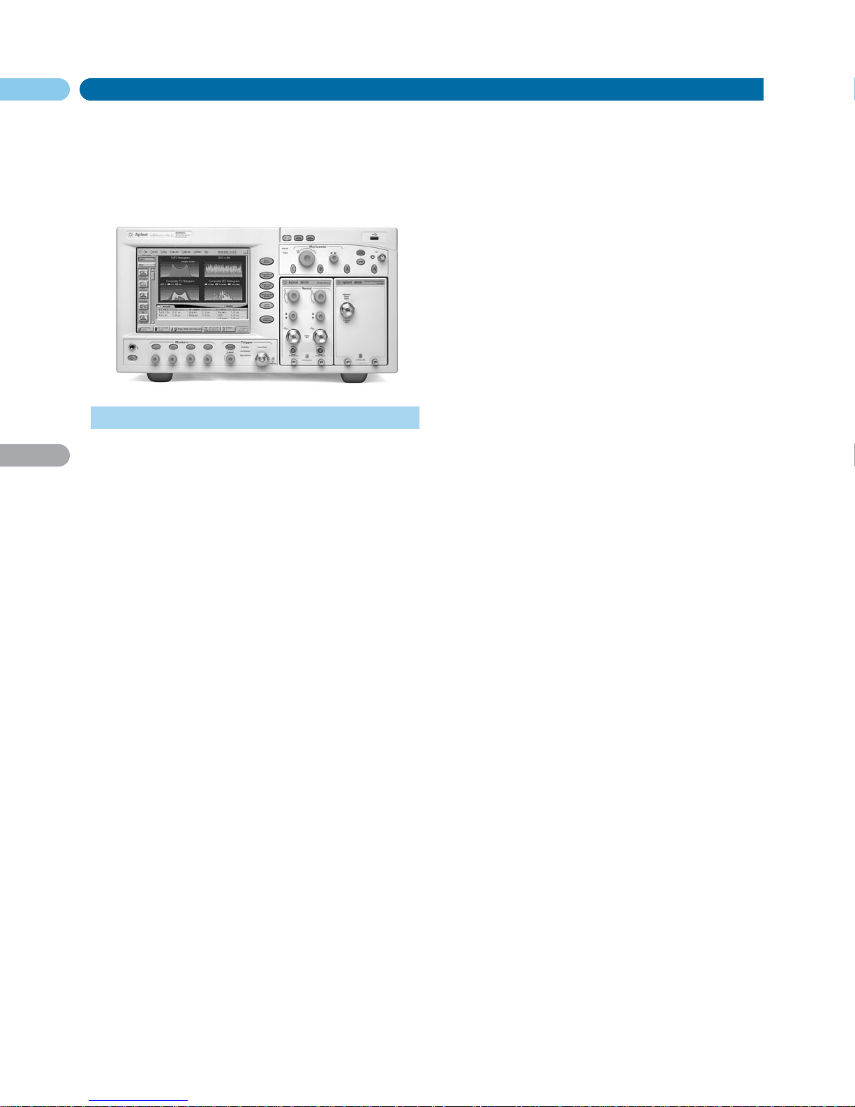
72
86100C
DCA-J
English URL www.agilent.com/find/products
3
Meeting Your Growing Need for More Bandwidth
Today’s high data-rate signals have significant frequency content
well beyond a real-time oscilloscope’s 3 dB bandwidth. A high bandwidth scope does not alone guarantee an accurate representation
of your waveform. Careful design of the DCA-J equivalent time sampling oscilloscope’s frequency response (both amplitude and phase)
minimizes distortion such as overshoot and ringing allowing the
most precise signal analysis available from 50 Mb/s to over
40 Gb/s.
Four Instruments in One
The 86100C Infiniium DCA-J can be viewed as four high-powered
instruments in one:
• A general-purpose wide-bandwidth sampling oscilloscope; the
new PatternLock triggering significantly enhances the usability
as a general purpose scope
• A digital communications analyzer; the new Eyeline Mode
feature adds a powerful new tool to eye diagram analysis
• A time domain reflectometer
• A jitter and amplitude interference analyzer
In addition the 86100C Infiniium DCA-J can measure:
• Relative Intensity Noise (RIN) of lasers modulated with industrystandard PRBS signals
• Characterize the jitter spectrum of clock or data signals found in
many computer architectures
• Lock its clock recovery onto Source Spectrum Clocking (SSC)
signals
Configurable to Meet Your Needs
The 86100C supports a wide range of modules for testing both
optical and electrical signals. Select modules to get the specific
bandwidth and sensitivity you need.
86100C Infiniium DCA-J
Optical/Transmission
Signal Integrity Analysis
The unique combination of wide bandwidth and low noise makes the
DCA-J the most precise signal integrity analyzer available. Accurate
eye-diagram analysis is essential for characterizing the quality
of transmitters used from 50 Mb/s to 40 Gb/s and the DCA-J is
designed specifically for the complex task of analyzing digital waveforms. Compliance mask and parametric testing can be performed
with the touch of a single button.
Jitter and Amplitude Interference Analysis
Extremely wide bandwidth, low intrinsic jitter, and advanced analysis algorithms yield the highest accuracy in jitter measurements. As
data rates increase in both electrical and optical applications,
decomposition of jitter and amplitude interference into its
constituent components is becoming more critical. It provides
critical insight for jitter and amplitude budgeting and performance
optimization in device and system designs. Many emerging
standards require jitter decomposition for compliance. The DCA-J
provides simple, one button setup and execution of advanced
waveform analysis. Jitter Mode decomposes jitter and amplitude
interference into its constituent components and presents jitter
data in various insightful displays. Jitter Mode operates at all data
rates the DCA-J supports. The 86100C brings several key attributes
to jitter analysis:
• Very low intrinsic jitter (both random and deterministic)
translates to the lowest jitter noise floor available providing
unmatched jitter measurement sensitivity
• Wide bandwidth measurement channels with very low intrinsic
jitter allow jitter and interference analysis on all data rates to
40 Gb/s and beyond
• Optimized frequency response (magnitude and phase) results in
more accurate waveform representation
Internal Triggering Through Clock Recovery
Typically an external timing reference is used to trigger an equivalent time sampling oscilloscope to the test signal. In cases where
a trigger signal is not available, clock recovery modules with
adjustable PLL loop bandwidth are used to derive a timing reference
directly from the waveform and provide golden PLL functionality for
testing to industry standards.
PatternLock Triggering
The Enhanced Trigger Option (Option 001) enables the DCA-J
to generate a trigger at the repetition of the input data pattern –
a pattern trigger. PatternLock automatically detects the pattern
length, data rate and clock rate enabling the 86100C to behave more
like a real-time oscilloscope in terms of user experience. Users that
are familiar with real-time oscilloscopes, but perhaps less so with
equivalent time sampling scopes will be able to ramp up quickly.
Time Domain Reflectometry/Time Domain Transmission
(TDR/TDT)
High-speed design starts with the physical structure. The transmission and reflection properties of electrical channels and components
must be characterized to ensure sufficient signal integrity.
Use TDR and TDT to optimize microstrip lines, PC board
traces, SMA edge launchers and coaxial cables.
Calibration techniques, unique to the DCA-J, provide the highest precision by removing cabling and fixturing effects from the
measurement results. Translation of TDR data to complete singleended, differential, and mixed mode S-parameters are available
through the N1930A Physical Layer Test System software.
For specifications and ordering information refer to pages
76-79.
• Modular platform for testing electrical and optical waveforms to
40 Gb/s and beyond
• Automated jitter and interference decomposition
• Internally generated pattern trigger
• Broadest coverage of data rates
• RIN measurements on PRBS signals
• Jitter spectrum of clock or data signals
Page 26
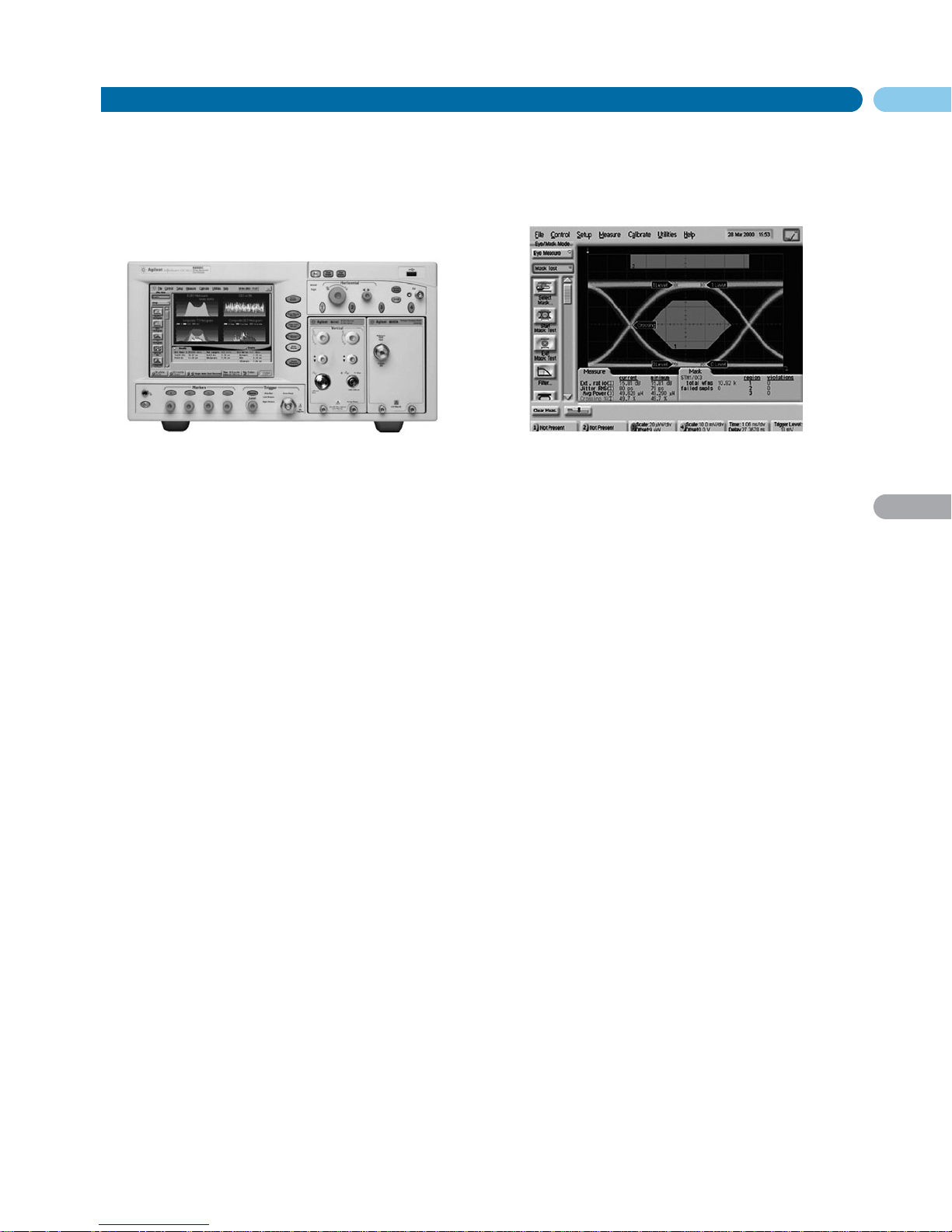
73
86100C
DCA-J
English URL www.agilent.com/find/products
3
86100C Infiniium DCA-J (cont.)
Optical/Transmission
The ultimate flexible tool – the 86100C Infiniium DCA-J with
advanced jitter analysis. Four instruments in one – a digital communications analyzer with automated eye measurements; a full-function time domain reflectometer (TDR) for impedance analysis; a full
function oscilloscope with bandwidth in excess of 80 GHz; an innovative and accurate jitter analyzer for electrical and optical signals.
With the ability to accept plug-in modules that you already own from
the 83480A/54750A and 86100A/B, the DCA-J also protects your
investment.
Capabilities
• Broadest coverage – receivers and clock recovery modules cover
widest range of data rates and wavelengths
• Pattern lock – internally generates pattern trigger from an
ordinary clock
• Eyeline mode – isolates specific bit sequences, creates an
averaged eye diagram
• Interference and jitter mode – one-button RJ/DJ, RN/DI
separation; accurate, stable, in-depth interference and jitter
analysis at any rate-even beyond 40 Gb/s
• Jitter analysis with the 86107A precision timebase – achieve
the most accurate jitter measurements with the lowest jitter
intrinsics of any enterprise jitter solution to measure ultra high
performance components
• TDR/TDT – accurately analyzes single-ended and differential
devices; built-in calibration removes cabling/fixture effects
• S-parameters – one button push shows you reflection and
transmission parameters – Option 202 and TDR
• Open operating system – Windows® XP Pro allows external
applications to be installed
Eye Diagram Mask Testing
The DCA-J provides efficient, high-throughput waveform compliance testing with a suite of standards based eye-diagram masks. The
test process has been streamlined into a minimum number of
keystrokes for testing at industr y standard data rates.
• Essential tools for the high speed digital designer
• Wide bandwidth oscilloscope
• Communications analyzer
• Signal integrity analyzer
• Interference and jitter analyzer
• RIN measurements on PRBS signals
• Jitter spectrum of clock and data signals
Standard Masks
Rate (Mb/s)
• 1X Gigabit Ethernet 1250
• 2X Gigabit Ethernet 2500
• 10 Gigabit Ethernet 9953.28
• 10 Gigabit Ethernet 10312.5
• 10X Gigabit Ethernet FEC 11095.7
• Fibre Channel 1062.5
• 2X Fibre Channel 2125
• 4X Fibre Channel 4250
• 8X Fibre Channel 8500
• 10X Fibre Channel 10518.75
• 10X Fibre Channel FEC 11317
• STM0/OC1 51.84
• STM1/OC3 155.52
• STM4/OC12 622.08
• STM16/OC48 2488.3
• STM16/OC48 FEC 2666
• Infiniband 2500
• 10 Gigabit Ethernet LX4 3125
• STM64/OC192 9953.28
• STM64/OC192 FEC 10664.2
• STM64/OC192 FEC 10709
• STM64/OC192 Super FEC 12500
• STM256/OC768 39813
• STS1 EYE 51.84
• STS3 EYE 155.52
Other eye-diagram masks are easily created through scaling.
In addition, mask editing allows for new masks either by editing
existing masks, or creating new masks from scratch. A new mask
can also be created or modified on an external PC using a text editor
such as Notepad, then can be transferred to the instrument’s hard
drive using LAN, Flash drive, or USB devices.
Perform these mask conformance tests with convenient
user-definable measurement conditions, such as mask margins for
guardband testing, number of waveforms tested, and stop/limit
actions.
Page 27
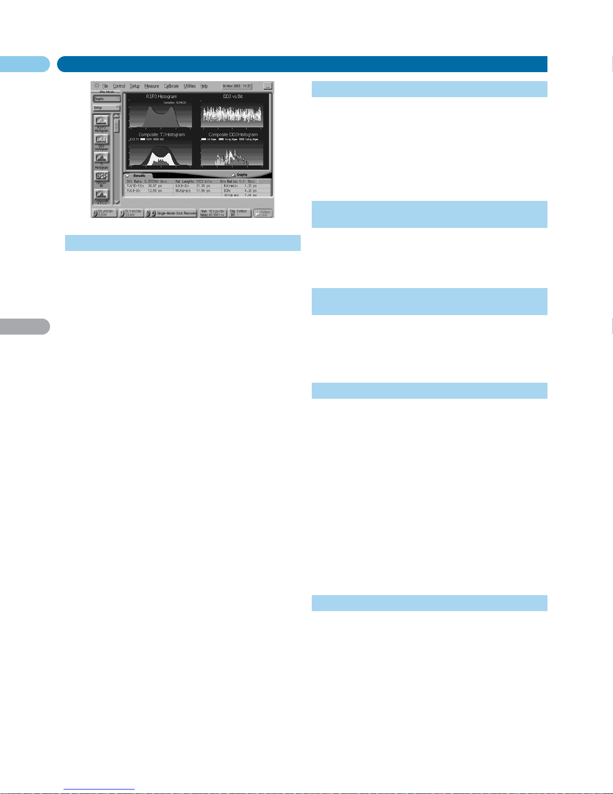
74
86100C
DCA-J
3
86100C Infiniium DCA-J (cont.)
Optical/Transmission
Jitter Mode
Jitter Mode decomposes jitter and amplitude interference into its
constituent components and presents jitter data in various insightful displays. Jitter Mode operates at all data rates the DCA-J supports, removing the traditional data rate limitations from complex
jitter analysis. The DCA-J brings several key attributes to jitter
analysis:
• Very low intrinsic jitter (both random and deterministic) translates to a very low jitter noise floor which provides unmatched
jitter measurement sensitivity
• Wide bandwidth measurement channels deliver very low intrinsic data dependent jitter and allow analysis of jitter on all data
rates to 40 Gb/s and beyond
• PatternLock triggering technology provides sampling efficiency
that makes jitter measurements very fast
Analysis functionality is segmented into three software package options. Option 200 is the enhanced jitter analysis software, and
Option 201 is the advanced waveform analysis software. Option 300
provides amplitude analysis and RIN. Option 200 includes:
• Decomposition of jitter into Total Jitter (TJ), Random Jitter (RJ),
Deterministic Jitter (DJ), Periodic Jitter (PJ), Data Dependent
Jitter (DDJ), Duty Cycle Distortion (DCD), and Jitter induced by
Intersymbol Interference (ISI)
• Various graphical and tabular displays of jitter data
• Export of jitter data to convenient delimited text format
• Save/recall of jitter database
• Jitter frequency spectrum
• Isolation and analysis of Sub-Rate Jitter (SRJ), that is, periodic
jitter that is at an integer sub-rate of the bitrate
• Bathtub curve display
• Adjustable total jitter probability
As bit rates increase, channel effects cause significant eye
closure. Many new devices and systems are employing equalization
and pre/de-emphasis to compensate for channel effects. Option 201
Advanced Waveform Analysis will provide key tools to enable design
and test of devices and systems that must deal with difficult channel
effects:
• Capture of long single valued waveforms. PatternLock triggering
and the waveform append capability of Option 201 enable very
accurate pulse train data sets up to 2 x 10
23
bits long
• Equalization. The DCA-J can take a long single valued waveform
and route it through an equalizer algorithm (default or user
defined) and display the resultant equalized waveform in real
time. The user can simultaneously view the input (distorted) and
output (equalized) waveforms
• Interface to MatLab® analysis capability
Option 300 includes:
• Decomposition of amplitude interference into total interference
(TI), deterministic interference (DI), random noise (RN), data
dependent interference (DDI), inter-symbol interference (ISI),
and periodic interference (PI)
• Various graphical and tabular displays of interference
measurements
• Relative Intensity Noise (RIN 1 level or RIN OMA) using
square-wave or industry-standard PRBS patterns
• Q-factor measurement
Option 300 requires options 200 (enhanced jitter software)
and 001 (enhanced trigger hardware).
Internal Triggering Through Clock Recovery
Typically an external timing reference is used to synchronize the
oscilloscope to the test signal. In cases where a trigger signal is not
available, clock recovery modules are available to derive a timing
reference directly from the waveform to be measured.
The 83496B provides the highest performance/flexibility as it
is capable of operation at any data rate from 50 Mb/s to 13.5 Gb/s, on
single-ended and differential electrical signals, single mode (1250 to
1620 nm) and multimode (780 to 1330 nm) optical signals, with
extremely low residual jitter. PLL loop bandwidth is adjustable to
provide optimal jitter filtering according to industry test standards.
Stimulus Response Testing Using the Agilent
N490xA/B Bit Error Ratio Tester
Error performance analysis represents an essential part of digital
transmission test. The DCA-J and Agilent N490xA/B Bit Error Ratio
Tester error performance analyzer come together to create a powerful test solution where two instruments together can perform measurements that would otherwise be impossible.
Transitioning from the Agilent 83480A or
86100A/B to the Infiniium DCA-J
The 86100C Infiniium DCA-J has been designed to be a virtual dropin replacement for the Agilent 83480A digital communications analyzer and Agilent 54750A wide-bandwidth oscilloscope. All modules
used in the Agilent 83480A, 54750A, and 86100A/B can also be used
in the 86100C Infiniium DCA-J. Some newer modules (such as the
86116C and the 83496B) work only in the 86100C Infiniium DCA-J.
Eyeline Mode
Eyeline Mode is a new feature only available in the DCA-J that provides insight into the effects of specific bit transitions within a data
pattern. The unique view assists diagnosis of device or system failures do to specific transitions or sets of transitions within a pattern.
When combined with mask limit tests, Eyeline Mode can quickly
isolate the specific bit that caused a mask violation.
Traditional triggering methods on an equivalent time sampling
scope are quite effective at generating eye diagrams. However, these
eye diagrams are made up of samples whose timing relationship to
the data pattern is effectively random, so a given eye will be made up
of samples from many different bits in the pattern taken with no
specific timing order. The result is that amplitude versus time trajectories of specific bits in the pattern are not visible. Also, averaging of the eye diagram is not valid, as the randomly related samples
will effectively average to zero.
Eyeline Mode uses PatternLock triggering to build up an eye
diagram from samples taken sequentially through the data pattern.
This maintains a specific timing relationship between samples and
allows Eyeline Mode to draw the eye based on specific bit trajectories. Effects of specific bit transitions can be investigated, and averaging can be used with the eye diagram.
Measurements
The following measurements are available from the tool bar, as well
as the pull down menus. The available measurements depend on the
DCA-J operating mode.
Jitter Mode
Jitter Mode requires Option 001 Enhanced Trigger hardware.
There are three analysis software packages for the DCA-J. Option 200 is
the enhanced jitter analysis software, Option 201 is the advanced waveform analysis software, and option 300 is the advanced amplitude
analysis software.
Measurements (Option 200 Jitter Analysis)
Total Jitter (TJ), Random Jitter (RJ), Deterministic Jitter (DJ), Periodic
Jitter (PJ), Data Dependent Jitter (DDJ), Duty Cycle Distortion (DCD),
Intersymbol Interference (ISI), Sib-Rate Jitter (SRJ)
Page 28
75
86100C
DCA-J
English URL www.agilent.com/find/products
3
86100C Infiniium DCA-J (cont.)
Optical/Transmission
Data Displays (Option 200 Jitter Analysis)
TJ histogram, RJ/PJ histogram, DDJ histogram, Composite histogram,
DDJ versus Bit position, Composite DDJ, Bathtub curve, PJ Analysis,
SRJ analysis, Aliased Spectrum, PJ Waveforms
Measurements (Option 201 Advanced Waveform Analysis)
Pattern waveform
Data Displays (Option 201 Advanced Waveform Analysis)
Equalized waveform
Measurements (Option 300 Advanced Amplitude Analysis)
Total Interference (TI), Deterministic Interference (DI), Random Noise
(RN), Data Dependent Interference (DDI), Inter-Symbol Interference (ISI),
Periodic Interference (PI)
Data Displays (Option 300 Advanced Amplitude Analysis)
TI histogram, RI/PI histogram, DDI histogram, Composite histogram, DDI
versus Bit position
Oscilloscope Mode
Time
Rise Time, Fall Time, Jitter RMS, Jitter p-p, Period, Frequency, + Pulse
Width, – Pulse Width, Duty Cycle, Delta Time, [Tmax, Tmin, Tedge –
remote commands only]
Amplitude
Overshoot, Average Power, V amptd, V p-p, V rms, V top, V base, V max,
V min, V avg, Optional Modulation
Amplitude (OMA)
86100C Family Plug-in Module Matrix
Module Option Number Number Wavelength Unfiltered Electrical Fiber Mask
of of Range Optical Bandwidth Input Test
Optical Electrical (nm) Bandwidth (GHz) (µm) Sensitivity Probe
Channels Channels (GHz) (dBm) Power
1
Optical/Electrical
86105B 111 1 1 1000 – 1600 15 20 9 –12 •••••••
112 1 1 1000 – 1600 15 20 9 –12 • • • • •••••••
113 1 1 1000 – 1600 15 20 9 –12 •••• •••••••
86105C 10021 1 750 – 1650 8.5 20 62.5 –20 ••••••••••••
200 1 1 750 – 1650 8.5 20 62.5 –16 •••••••
30021 1 750 – 1650 8.5 20 62.5 –16 •••••••••••••••••••
86106B 1 1 1000 – 1600 28 40 9 –7 • •
410 1 1 1000 – 1600 28 40 9 –7 • •••••
86116A 1 1 1000 – 1600 53 63 9 — •
86116B 1 1 1480 – 1620 65 80 9 —
86116C
1,3
1 1 1480 – 1620 65 80 9 –3 • •
Dual/Electrical
54754A 0 2 — — 18 — — •
86112A 0 2 — — 20 — — •
86117A 0 2 — — 50 — —
86118A 0 2 — — 70 — —
1
Module has receptacle to supply power for external probe. For modules without a probe power receptacle, use the 1143A Probe Power Supply.
2
Pick any 4 rates (155 Mb/s to 8.5 Gb/s).
3
This module is not compatible with the 86100A and 86100B Digital Communication Analyzer (DCA) mainframes. If you would like to upgrade older DCAs contact Agilent Technologies
and ask for current trade-in deals.
Filtered Data Rates
Mb/s Gb/s
Eye/Mask Mode
NRZ Eye Measurements
Extinction Ratio, Jitter RMS, Jitter p-p, Average Power, Crossing
Percentage, Rise Time, Fall Time, One Level, Zero Level, Eye Height, Eye
Width, Signal to Noise (Q-Factor), Duty Cycle Distortion, Bit Rate, Eye
Amplitude
RZ Eye Measurements
Extinction Ratio, Jitter RMS, Jitter p-p, Average Power, Rise Time, Fall
Time, One Level, Zero Level, Eye Height, Eye Amplitude, Opening Factor,
Eye Width, Pulse Width, Signal to Noise (Q-Factor), Duty Cycle, Bit Rate,
Contrast Ratio
Mask Test
Open Mask, Start Mask Test, Exit Mask Test, Filter, Mask Test Margins,
Mask Test Scaling, Create NRZ Mask
TDR/TDT Mode (requires TDR module)
Quick TDR, TDR/TDT Setup, Normalize, Response, Rise Time, Fall Time,
Δ Time
Modules for the Agilent 86100C Infiniium DCA-J
The Infiniium DCA has a large family of plug-in modules designed
for a broad range of data rates for optical and electrical waveforms.
The DCA-J can hold up to 2 modules for a total of 4 measurement
channels.
155
622
1063
1244/1250
2125
2488/2500
2.666
3.125
4.25
5.00
6.25
8.500
9.953
10.3125
10.51875
10.664
10.709
11.096
11.317
39.813
43.018
Page 29

76
86106B
86116A
86116B
86116C
English URL www.agilent.com/find/products
3
86100C Infiniium DCA-J (cont.)
Optical/Transmission
Module Specifications: 86106B, 86116A/B/C
High Bandwidth, Single-mode Optical/ 86106B 86116A
1
86116B
1
86116C
1
Electrical Modules
Optical Channel Specifications
Optical Channel Unfiltered Bandwidth 28 GHz 53 GHz 65 GHz (best pulse fidelity) 65 GHz
Wavelength Range 1000 to 1600 nm 1480 to 1620 nm 1480 to 1620 nm
Calibrated Wavelengths 1310/1550 nm 1550 nm 1550 nm
Optical Sensitivity
3
–7 dBm –3 dBm
Transition Time (10% to 90%, calculated 18 ps 9.0 ps (FWHM)
2
7.4 ps (FWHM)
2
7.4 ps (FWHM)
2
from TR = 0.48/BW optical)
RMS Noise
Characteristic 13 µW (Filtered) 60 µW (50 GHz) 50 µW (55 GHz) 36 µW (39.8, 43.0 Gb/s filters)
23 µW (Unfiltered) 190 µW (53 GHz) 140 µW (65 GHz) 125 µW (65 GHz)
Maximum 15 µW (Filtered) 90 µW (50 GHz) 85 µW (55 GHz) 68 µW (39.8, 43.0 Gb/s filters)
30 µW (Unfiltered) 260 µW (53 GHz) 250 µW (65 GHz) 200 µW (65 GHz)
Scale Factor
Minimum 20 µW/division 200 µW/division 200 µW/division 200 µW/division
Maximum 500 µW/division 2.5 mW/division 5 mW/division 5 mW/division
CW Accuracy (single marker, referenced ±50 µW ± 4% of ±150 µW ± 4% of ±150 µW ± 4% of ±150 µW ± 4% of
to average power monitor) (reading-channel offset) (reading-channel offset) (reading-channel offset) (reading-channel offset)
CW Offset Range (referenced two +1 mW to –3 mW +5 mW to –15mW +8 to –12 mW +8 to –12 mW
divisions from screen bottom)
Average Power Monitor –27 dBm to +3 dBm –23 dBm to +9 dBm –23 dBm to +9 dBm –23 dBm to +9 dBm
(specified operating range)
Factory Calibrated Accuracy ±5% ± 100 nW ± connector uncertainty, 20°C to 30°C
User Calibrated Accuracy ±2% ± 100 nW ± power meter uncertainty, <5°C change
Maximum Input Power
Maximum non-destruct average 2 mW (+3 dBm) 10 mW (+10 dBm) 10 mW (+10 dBm) 10 mW (+10 dBm)
Maximum non-destruct peak 10 mW (+10 dBm) 50 mW (+17 dBm) 50 mW (+17 dBm) 50 mW (+17 dBm)
Fiber Input 9/125 µm, user selectable connector
Input Return Loss 30 dB 30 dB 20 dB 20 dB
(HMS-10 connector fully filled fiber)
Electrical Channel Specifications
Electrical Channel Bandwidth 18 and 40 GHz 43 and 63 GHz 80, 55 and 30 GHz 80, 55 and 30 GHz
Transition Time (10% to 90%, 19.5 ps (18 GHz) 8.1 ps (43 GHz) 6.4 ps (55 GHz) 6.4 ps (55 GHz)
calculated from TR = 0.35/BW) 9 ps (40 GHz) 5.6 ps (63 GHz) 4.4 ps (80 GHz) 4.4 ps (80 GHz)
RMS Noise
Characteristic 0.25 mV (18 GHz) 0.6 mV (43 GHz) 0.6 mV (55 GHz) 0.5 mV (30 GHz)
0.5 mV (40 GHz) 1.7 mV (63 GHz) 1.1 mV (80 GHz) 1.1 mV (80 GHz)
Maximum 0.5 m V (18 GHz) 0.9 mV (43 GHz) 1.1 mV (55 GHz) 0.8 mV (30 GHz)
1.0 mV (40 GHz) 2.5 mV (63 GHz) 2.2 mV (80 GHz) 2.2 mV (80 GHz)
Scale Factor
Minimum 1 mV/division 2 mV/division 2 mV/division 2 mV/division
Maximum 100 mV/division 100 mV/division 100 mV/division 100 mV/division
DC Accuracy (single marker) ±0.4% of full scale ±0.8% of full scale ±0.4% of full scale ±0.4% of full scale
±2 mV ± 1.5% of (reading- ±2 mV ± 1.5% of (reading- ±3 mV ± 2% of (reading- ±3 mV ± 2% of (readingchannel offset), 18 GHz channel offset), 43 GHz channel offset), ± 2% of channel offset), ± 2% of
±0.4% of full scale ±2.5% of full scale offset (all bandwidths) offset (all bandwidths)
±2 mV ± 3% of (reading- ±2 mV ± 2% of (readingchannel offset), 40 GHz channel offset), 63 GHz
DC Offset Range (referenced to ±500 mV ±500 mV ±500 mV ±500 mV
center of screen)
Input Dynamic Range (relative to ±400 mV ±400 mV ±400 mV ±400 mV
channel offset)
Maximum Input Signal ±2 V (+16 dBm) ±2 V (+16 dBm) ±2 V (+16 dBm) ±2 V (+16 dBm)
Nominal Impedance 50 Ω 50 Ω 50 Ω 50 Ω
Reflections (for 20 ps rise time) 5% 5% 10% (DC to 70 GHz) 10% (DC to 70 GHz)
20% (70 to 100 GHz) 20% (70 to 100 GHz)
Electrical Input 2.4 mm (male) 1.85 mm (male) 1.85 mm (male) 1.85 mm (male)
1
86116A and 86116B require the 86100 software revision A.3.0 or above. 86116C requires an 86100C mainframe and software revision 7.0.
2
FWHM (Full Width Half Max) as measured from optical pulse with 700 fs FWHM, 5 MHz repetition rate and 10 mW peak power.
3
Smallest average optical power required for mask test. Values represent typical sensitivity of NRZ eye diagrams. Assumes mask test with compliance filter switched in.
Page 30

77
86105B
86105C
English URL www.agilent.com/find/products
3
86100C Infiniium DCA-J (cont.)
Optical/Transmission
Module Specifications: Single-mode & Multimode Optical/Electrical
Multimode and Single-mode Optical/Electrical Modules 86105B 86105C
Optical Channel Specifications
Optical Channel Unfiltered Bandwidth 15 GHz 8.5 GHz (9 GHz)
Wavelength Range 1000 to 1600 nm 750 to 1650 nm
Calibrated Wavelengths 1310 nm/1550 nm 850 nm/1310 nm/1550 nm (±20 nm)
Optical Sensitivity
1
–12 dBm 850 nm
≤2.666 Gb/s, –20 dBm
>2.666 Gb/s to ≤4.25 Gb/s, –19 dBm
>4.5 Gb/s to 11.3 Gb/s, –16 dBm
1310 nm/1550 nm
≤2.666 Gb/s, –21 dBm
>2.666 Gb/s to ≤4.25 Gb/s, –20 dBm
>4.25 Gb/s to 11.3 Gb/s, –17 dBm
Transition Time (10% to 90% calculated from TR=0.48/BW optical) 32 ps 56 ps
RMS Noise
Characteristic 5 µW, (10 GHz) 850 nm
12 µW, (15 GHz) ≤2.666 Gb/s, 1.3 µW
>2.666 Gb/s to ≤4.25 Gb/s, 1.5 µW
>4.25 Gb/s to 11.3 Gb/s, 2.5 µW
1310 nm/1550 nm
≤2.666 Gb/s, 0.8 µW
>2.666 Gb/s to ≤4.25 Gb/s, 1.0 µW
>4.25 Gb/s to 11.3 Gb/s, 1.4 µW
Maximum 8 µW, (10 GHz) 850 nm
15 µW, (15 GHz) ≤2.666 Gb/s, 2.0 µW
>2.666 Gb/s to ≤4.25 Gb/s, 2.5 µW
>4.25 Gb/s to 11.3 Gb/s, 4.0 µW
1310 nm/1550 nm
≤2.666 Gb/s, 1.3 µW
>2.666 Gb/s to ≤4.25 Gb/s, 1.5 µW
>4.25 Gb/s to 11.3 Gb/s, 2.5 µW
Scale Factor (per division)
Minimum 20 µW 2 µW
Maximum 500 µW 100 µW
CW Accuracy (single marker, referenced to average power monitor) ±25 µW ± 2% (10 GHz) ±25 µW ± 3%
±25 µW ± 4% (15 GHz) ±25 µW ± 10%
CW Offset Range (referenced two divisions from screen bottom) +1 µW to –3 µW +0.2 µW to –0.6 µW
Average Power Monitor (specified operating range) –30 dBm to +3 dBm –30 dBm to 0 dBm
Average Power Monitor Accuracy
Single-mode ±5% ± 100 nW ± connector uncertainty ±5% ± 200 nW ± connector uncertainty
(20°C to 30°C)
Multimode (characteristic) — ±10% ± 200 nW ± connector uncertainty
User Calibrated Accuracy
Single-mode ±2% ± 100 nW ± power meter ±3% ± 200 nW ± power meter
uncertainty, <5°C change uncertainty, <5°C change
Multimode (characteristic) — ±10% ± 200 nW ± power meter
uncertainty, <5°C change
Maximum Input Power
Maximum Non-destruct Average 2 µW (+3 dBm) 0.5 µW (–3 dBm)
Maximum Non-destruct Peak 10 µW (+10 dBm) 5 µW (+7 dBm)
Fiber Input 9/125 µm user selectable connector 62.5/125 µm
Input Return Loss (HMS-10 connector fully filled fiber) 33 dB 850 nm
>13 dB ,
1310 nm/1550 nm
>24 dB
1
Smallest average optical power required for mask test. Values represent typical sensitivity of NRZ eye diagrams. Assumes mask test with compliance filter switched in.
Page 31

78
86105B
86105C
English URL www.agilent.com/find/products
3
86100C Infiniium DCA-J (cont.)
Optical/Transmission
Module Specifications: Single-mode & Multimode Optical/Electrical
Multimode and Single-Mode Optical/Electrical Modules 86105B/C
Electrical Channel Specifications
Electrical Channel Bandwidth 12.4 and 20 GHz
Transition Time (10% to 90%, calculated from TR = 0.35/BW) 28.2 ps (12.4 GHz)
17.5 ps (20 GHz)
RMS Noise
Characteristic 0.25 mV (12.4 GHz)
0.5 mV (20 GHz)
Maximum 0.5 mV (12.4 GHz)
1 mV (20 GHz)
Scale Factor
Minimum 1 mV/division
Maximum 100 mV/division
DC Accuracy (single marker) ±0.4% of full scale ± 2 mV ± 1.5% of (reading-channel offset), 12.4 GHz
±0.4% of full scale ± 2 mV ± 3% of (reading-channel offset), 20 GHz
DC Offset Range (referenced to center of screen) ±500 mV
Input Dynamic Range (relative to channel offset) ±400 mV
Maximum Input Signal ±2 V (+16 dBm)
Nominal Impedance 50 Ω
Reflections (for 30 ps rise time) 5%
Electrical Input 3.5 mm (male)
Page 32

79
54754A
86112A
86117A
86118A
English URL www.agilent.com/find/products
3
86100C Infiniium DCA-J (cont.)
Optical/Transmission
Module Specifications: Dual Electrical
Dual Electrical Channel Modules 86112A 54754A
Electrical Channel Bandwidth 12.4 and 20 GHz 12.4 and 18 GHz
Transition Time 28.2 ps (12.4 GHz); 28.2 ps (12.4 GHz);
(10% to 90%, calculated from TR = 0.35/BW) 17.5 ps (20 GHz) 19.4 ps (18 GHz)
RMS Noise
Characteristic 0.25 mV (12.4 GHz); 0.25 mV (12.4 GHz);
0.5 mV (20 GHz) 0.5 mV (18 GHz)
Maximum 0.5 mV (12.4 GHz); 0.5 mV (12.4 GHz);
1 mV (20 GHz) 1 mV (18 GHz)
Scale Factor
Minimum 1 mV/division 1 mV/division
Maximum 100 mV/division 100 mV/division
DC Accuracy (single marker) ±0.4% of full scale ±0.4% of full scale
±2 mV ± 1.5% of (reading-channel offset), 12.4 GHz ±2mV ± 0.6% of (reading-channel offset), 12.4 GHz
±0.4% of full scale ±0.4% of full scale or marker reading
±2 mV ± 3% of (reading-channel offset), 20 GHz (whichever is greater)
±2 mV ± 1.2% of (reading-channel offset), 18 GHz
CW Offset Range (referenced from center of screen) ±500 mV ±500 mV
Input Dynamic Range (relative to channel offset) ±400 mV ±400 mV
Maximum Input Signal ±2 V (+16 dBm) ±2 V (+16 dBm)
Nominal Impedance 50 Ω 50 Ω
Reflections (for 30 ps rise time) 5% 5%
Electrical Input 3.5 mm (male) 3.5 mm (male)
TDR Module 54754A
TDR Step Rise Time
Oscilloscope/TDR Performance 40 ps nominal
Normalized Characteristics Adjustable from larger of 10 ps or 0.08 x time/division. Maximum: 5 x time/division
TDR Step Flatness
Oscilloscope/TDR Performance ≤±1% after 1 ns from edge; ≤±5% less than 1 ns from edge
Normalized Characteristics ≤0.1%
Low Level 0.00 V ± 2 mV
High Level +200 mV ± 2 mV
Dual Electrical Channel Modules 86117A 86118A
Electrical Channel Bandwidth 30 and 50 GHz 50 and 70 GHz
Transition Time 11.7 ps (30 GHz) —
(10% to 90%, calculated from TR = 0.35/BW) 7 ps (50 GHz)
RMS Noise
Characteristic 0.4 mV (30 GHz) 0.7 mV (50 GHz)
0.6 mV (50 GHz) 1.3 mV (70 GHz)
Maximum 0.7 mV (30 GHz) 1.8 mV (50 GHz)
1.0 mV (50 GHz) 2.5 mV (70 GHz)
Scale Factor
Minimum 1 mV/division 1 mV/division
Maximum 100 mV/division 100 mV/division
DC Accuracy (single marker) ±0.4% of full scale ±0.4% of full scale
±2 mV ± 1.2% of (reading-channel offset) (30 GHz) ±2 mV ± 2% of (reading-channel offset) (50 GHz)
±0.4% of full scale ±0.4% of full scale
±2 mV ± 2% of (reading-channel offset) (50 GHz) ±2 mV ± 4% of (reading-channel offset) (70 GHz)
CW Offset Range (referenced from center of screen) ±500 mV ±500 mV
Input Dynamic Range (relative to channel offset) ±400 mV ±400 mV
Maximum Input Signal ±2 V (+16 dBm) ±2 V (+16 dBm)
Nominal Impedance 50 Ω —
Reflections (for 30 ps rise time) 5% 20%
Electrical Input 2.4 mm (male) 1.85 mm (female)
Page 33

80
86100C
DCA-J
86100C Infiniium DCA-J (cont.)
Optical/Transmission
Ordering Information
86100C Infiniium DCA-J Mainframe
86100C-001 Enhanced Trigger
86100CS-001 Enhanced Trigger Upgrade Kit
86100C-701 Standard Trigger (default)
86100C-090 Removable Hard Drive
86100C-092 Internal Hard Drive (default)
86100C-200 Jitter Analysis Software
86100CU-200 Enhanced Jitter Analysis Software Upgrade
86100C-201 Advanced Waveform Analysis Software
86100CU-201 Advanced Waveform Analysis Software Upgrade
86100C-202 Enhanced Impedance and S-parameter Software
86100CU-202 Enhanced Impedance and S-parameter Software Upgrade
86100C-300 Amplitude Analysis/RIN/Q-factor
86100CU-300 Amplitude Analysis/RIN/Q-factor Upgrade
86100C-AFP Module Slot Filler Panel
86100C-AX4 Rack Mount Flange Kit
86100C-AXE Rack Mount Flange Kit with Handles
86100C-UK6 Commercial Cal Certificate with Test Data
N4688A External CD-RW Drive
Optical/Electrical Modules
86105B 15 GHz Optical Channel; Single-mode, Unamplified
(1000 to 1600 nm), 20 GHz Electrical Channel
86105B-111 9.953, 10.3125, 10.51875, 10.664, 10.709, 11.096,
11.317 Gb/s
86105B-112 155, 622 Mb/s, 2.488, 2.5, 2.666, 9.953, 10.3125,
10.51875, 10.664, 10.709, 11.096, 11.317 Gb/s
86105B-113 1.063, 1.250, 2.125, 2.488, 2.5, 9.953, 10.3125,
10.51875, 10.664, 10.709, 11.096, 11.317 Gb/s
86105C 9 GHz Optical Channel; Single-mode and Multimode, Amplified
(750 to 1650 nm), 20 GHz Electrical Channel
86105C-100 155 Mb/s through 8.5 Gb/s (choose 4 data rates)
86105C-110 155 Mb/s
86105C-120 622 Mb/s
86105C-130 1.063 Gb/s
86105C-140 1.244/1.250 Gb/s
86105C-150 2.125 Gb/s
86105C-160 2.488, 2.500 Gb/s
86105C-170 2.666 Gb/s
86105C-180 3.125 Gb/s
86105C-190 4.250 Gb/s
86105C-193 5.0 Gb/s
86105C-195 6.250 Gb/s
86105C-197 8.500 Gb/s
86105C-200 9.953, 10.3125, 10.519, 10.664, 10.709, 11.096,
11.317 Gb/s
86105C-300 Combination of Rates Available in 86105C-100 and
86105C-200
86106B 28 GHz Optical Channel; Single-mode, Unamplified
(1000 to 1600 nm) 9.953 Gb/s, 40 GHz Electrical Channel
86106B-410 9.953, 10.3125, 10.664, 10.709 Gb/s
86116C 65 GHz optical channel; single-mode, unamplified
(1480 to 1620 nm), 80 GHz electrical channel. This module is not
compatible with the 86100A and 86100B DCA mainframes. If you want to
upgrade older DCAs, contact Agilent Technologies to discuss current
trade-in deals.
All optical modules have FC/PC connectors installed on each
optical port. Other connector adapters available as options are: Diamond
HMS-10, DIN, ST and SC.
Dual Electrical Channel Modules
86112A Dual 20 GHz Electrical Channels
86117A Dual 50 GHz Electrical Channels
86118A Dual 70 GHz Electrical Remote Sampling Channels
86118A-H01
Differential De-Skew
TDR/TDT Modules
Included with each of these TDR Modules is a TDR demo board,
programmers guide, two 50 Ω SMA Terminations and one SMA short.
54754A Differential TDR Module with Dual 18 GHz TDR/Electrical Channels
N1020A 6 GHz TDR Probe Kit
N1024A TDR Calibration Kit
Trigger Module
86107A Precision Timebase Reference Module
86107A-010 2.5 and 10 GHz Clock Input Capability
86107A-020 10 and 20 GHz Clock Input Capability
86107A-040 10, 20 and 40 GHz Clock Input Capability
Clock Recovery Modules
The following modules provide a recovered clock from the data signal for
triggering at indicated data rates:
83496A 50 Mb/s to 7.1 Gb/s Clock Recovery Module
83496A-100 Single-ended and Differential Electrical with Integrated
Signal Taps
83496A-101 Single-mode (1250 to 1620 nm) and Multimode
(780 to 1330 nm) Optical. Integrated Signal Taps. Single-ended
or Differential Electrical Inputs (no signal taps)
83496A-200 Increase Operating Range to 50 Mb/s to 13.5 Gb/s
83496AU-200 Upgrade Data Rate 0.05 Gb/s to 13.5 Gb/s
83496A-300 Add Tunable Loop Bandwidth “golden PLL” Capability
83496AU-300 Upgrade Adjustable Loop Bandwidth
83496B 50 Mb/s to 7.1 Gb/s clock recovery module. This module is not
compatible with the 86100A and 86100B DCA mainframes. If you want to
upgrade older DCAs, contact Agilent Technologies and ask for current
trade-in deals.
83496B-100 Single-ended and Differential Electrical with Integrated
Signal Taps
83496B-101 Single-mode (1250 to 1620 nm) and Multimode
(780 to 1330 nm) Optical. Integrated Signal Taps. Single-ended or
Differential Electrical Inputs (no signal taps)
83496B-200 Increase Operating Range to 50 Mb/s to 13.5 Gb/s
83496BU-200 Upgrade Data Rate 0.05 Gb/s to 13.5 Gb/s
83496B-201 Shift Operating Range to 7.1 to 13.5 Gb/s
83496BU-201 Upgrade Shift Operating Range to 7.1 to 13.5 Gb/s
83496B-300 Add Tunable Loop Bandwidth “golden PLL” Capability
83496BU-300 Upgrade Adjustable Loop Bandwidth
Warranty Options (for all products)
R1280A Customer Return Repair Service
R1282A Customer Return Calibration Service
Accessories
86101-60005 Filler Panel
0960-2427 USB Keyboard (included with 86100C)
1150-7799 USB Mouse (included with 86100C)
Note: 86100C-200 and 86100C-201 require Option 001 (enhanced trigger). 86100C-300
requires Options 200 and 001.
English URL www.agilent.com/find/products
3
Suggested Configurations for Common Applications
86100C Infiniium DCA-J Mainframe (option 1)
Electrical Electrical Optical Optical TDR
1 to 12 Gb/s 20, 40 Gb/s 1 to 12 Gb/s 20, 40 Gb/s
86112A 86118A 86105C 86116C 54754A
Dual channels Dual remote heads 9 GHz optical channel 65 GHz optical channel Differential TDR/
>20 GHz each 70 GHz each 20 GHz electrical channel 80 GHz electrical channel Dual 18 GHz channels
83496B 86107A 83496B 86107A
Electrical clock recovery Precision timebase Optical clock recovery Precision timebase
(#100, 200, 300) (#040) (#101, 200, 300) (#040)
Note: Other modules and options available. See the Technical Specifications, p/n 5989-0278EN or www.agilent.com for configuration details.
Page 34

81
86100C
DCA-J
86100C Infiniium DCA-J (cont.)
Optical/Transmission
Optical Connector Adapters
Optical modules come standard with one FC/PC connector adapter
81000 AI Diamond HMS-10 Connector
81000 FI FC/PC Connector Adapter
81000 SI DIN Connector Adapter
81000 VI ST Connector Adapter
81000 KI SC Connector Adapter
RF/Microwave Accessories
11667B Power Splitter, DC to 26.5 GHz, APC 3.5 mm
11667C Power Splitter, DC to 50 GHz, 2.4 mm
11742A 45 MHz to 26.5 GHz DC Blocking Capacitor
11742A-K01 50 GHz DC Blocking Capacitor
8490D-020 2.4 mm 20 dB Attenuator
11900B 2.4 mm (f-f) Adapter
11901B 2.4 mm (f) to 3.5 mm (f) Adapter
11901C 2.4 mm (m) to 3.5 mm (f) Adapter
11901D 2.4 mm (f) to 3.5 mm (m) Adapter
5061-5311 3.5 mm (f-f) Adapter
1250-1158 SMA (f-f) Adapter
1810-0118 3.5 mm Termination
Passive Probe
54006A 6 GHz Passive Probe
InfiniiMax I Active Probes (1.5 to 7 GHz)
The N1022A probe adapter is required to use these probes with the DCA-J
InfiniiMax I Probe Amplifiers
Order 1 or more InfiniiMax I probe head or connectivity kit for each
amplifier
1130A 1.5 GHz Probe Amplifier
1131A 3.5 GHz Probe Amplifier
1132A 5 GHz Iprobe Amplifier
1134A 7 GHz Probe Amplifier
InfiniiMax I Probe Heads
E2675A InfiniiMax Differential Browser Probe Head and Accessories.
Includes 20 Replaceable Tips and Ergonomic Handle. Order E2658A for
Replacement Accessories
E2676A InfiniiMax Single-ended Browser Probe Head and Accessories.
Includes 2 Ground Collar Assemblies, 10 Replaceable Tips, a Ground Lead
Socket and Ergonomic Browser Handle. Order E2663A for Replacement
Accessories
E2677A InfiniiMax Differential Solder-in Probe Head and Accessories.
Includes 20 Full Bandwidth and 10 Medium Bandwidth Damping
Resistors. Order E2670A for Replacement Accessories
E2678A InfiniiMax Single-ended/Differential Socketed Probe Head and
Accessories. Includes 48 Full Bandwidth Damping Resistors, 6 Damped
Wire Accessories, 4 Square Pin Sockets and Socket Heatshrink. Order
E2671A for Replacement Accessories
E2679A InfiniiMax Single-ended Solder-in Probe Head and Accessories.
Includes 16 Full Bandwidth and 8 Medium Bandwidth Damping Resistors
and 24 Zero Ohm Ground Resistors. Order E2672A for Replacement
Accessories
InfiniiMax I Connectivity Kits (popular collections of the above probe
heads)
E2669A InfiniiMax Connectivity Kit for Differential Measurements
E2668A InfiniiMax Connectivity Kit for Single-ended Measurements
InfiniiMax II Active Probes (10 to 13 GHz)
The N1022A probe adapter is required to use these probes with the DCA-J
InfiniiMax II Probe Amplifiers
Order 1 or more InfiniiMax II probe heads for each amplifier. Infiniimax I
probe heads and connectivity kits can also be used but will have limited
bandwidth
1168A 10 Ghz Probe Amplifier
1169A 13 Ghz Probe Amplifier
InfiniiMax II Probe Heads
N5380A InfiniiMax II 12 GHz Differential SMA Adapter
N5381A InfiniiMax II 12 GHz Solder-in Probe Head
N5382A InfiniiMax II 12 GHz Differential Browser
Probe Adapters
N1022A Adapts 113x/115x/116x Active Probes to DCA-J
Connectivity Solutions
HDMI
N1080A H01 High Performance Coax Based HDMI Fixture with
Plug (TPA-P)
N1080A H02 High Performance Coax Based HDMI Fixture with
Receptacle (TPA-R)
N1080A H03 HDMI Low Frequency Board
SATA
iSATA Plug to SMA – COMAX P/N H303000104
iSATA Receptacle to SMA – COMAX P/N H303000204
These are available from COMAX Technology, see www.comaxtech.com
ATCA
Advanced TCA Tx/Rx Signal Blade™
Advanced TCA Tx/Rx Bench Blade™
These are available from F9 Systems, see www.f9-systems.com
Call Agilent for connectivity and probing solutions not listed above.
Firmware and Software
Firmware and Software Upgrades are available through the web or your
local sales office. www.agilent.com/find/dcaj
Upgrade Services
86100CS-001 Enhanced Trigger Hardware Upgrade
86100CU-200 Enhanced Jitter Analysis SW Upgrade
86100CU-201 Advanced Waveform Analysis SW Upgrade
86100CU-202 Enhanced Impedance and S-parameter Software Upgrade
86100CU-300 Advanced Amplitude Analysis SW Upgrade
83496A – 83496B Performance Upgrade Contact your local Agilent
Service Center and request Service Note 83496A-02
86100A/B to 86100C Upgrade Contact Agilent Technologies for current
trade-in deals
English URL www.agilent.com/find/products
3
Page 35

82
3
10070
Family
Choosing the Right Probe
Oscilloscope Probes & Accessories
English URL www.agilent.com/find/products
Recommended Oscilloscope/Probe Compatibility Chart
General Purpose Passive Probes
Low Mass Active Active
Oscilloscope 10:1 100:1 1000:1 1:1 10:1 Low Z 50 Ohm Single Ended Differential Current
DS03000A N2862A, 10076A N2771A 10070C — — — — 1141A
3
, N2772A 1146A,
N2863A N2780/1/2/3A
7
DS05000A N2863A, 10076A N2771A 10070C — — — 1156A, 1144A3, 1130A6, 1141A3, 1146A, 1147A,
10073C 1145A
3
N2772A N2780/1/2/3A
7
Infiniium 54810/15/20/25A 1160A 10440B2, N2771A 1162A — 1163A 10437B 1152A, 1155A, 1153A
2
1146A, 1147A,
1164A 10076A 1156A N2780/1/2/3A
Infiniium 54830/31/32/33B/D, 10073C, 10440B
2
, N2771A 1162A 1171A 1163A 10437B 1156A, 1155A, 1153A2, 1154A, 1146A, 1147A,
8000 Series 1165A 10076A 1159A, 1130A6N2780/1/2/3A
7
Infiniium 54835A, 1161A 10440B2, N2771A 1162A — 1163A 10437B 1152A2, 1155A2, 1153A2, 1154A, 1146A, 1147A,
54845A/B, 54846A/B 10076A 1156A 1159A, 1130/32A6N2780/1/2/3A
54751/52A/B — — — — — 54006A — 54701A
2, 4
1141A
3
—
54711/12/21/22A — — — — — 54006A — 54701A
4
1141A
3
—
54714/15A/13B 10441B, 10440B, N2771A 10439B, 1170A
1
10442B, 10437B 1144A3, 1145A3, 1141A
3
—
10073C 10076A 10070C 1163A
1
54701A
4
MSO/DSO6000 (300 MHz – 1 GHz) 10073C 10076A N2771A 10070C — — — 1156A, 11306, 1141A3, 1146A, 1147A
1144A3, 1145A3N2772A N2780/1/2/3A
7
MSO/DSO6000 (100 MHz) 10074C 10076A N2771A 10070C — — — — 1141A
2, 3
, 1146A,
N2772A N2780/1/2/3A
7
54645A/D 10074C 10440B, N2771A 10070C 1171A1— — 1144A
2, 3
, 1145A
2, 3
1141A
2, 3
, 1146A,
10076A N2772A N2780/1/2/3A
7
54621A/D 10074C 10440B, N2771A 10070C, 1171A1— — — 1141A
2, 3
1146A,
54622A/D/24A 10076A 10439B N2774A
5
54641A/D, 54642A/D 10073C 10440B, N2771A 10070C 1171A1— — 1144A3, 1145A31141A
3
1146A,
10076A N2780/1/2/3A
7
54615/16B/16C 10073C 10440B, N2771A 10070C, — 1163A1, 10437B 1144A3, 1145A31141A3, 1146A,
10076A 10439B 10442B N2772A N2780/1/2/3A
7
54610A/B 10073C 10440B, N2771A 10070C, — 1163A1, 10437B 1144A3, 1145A31141A3, 1146A,
10076A 10439B 10442B N2772A N2780/1/2/3A
7
54600/01/02/03A/B 10074C 10440B, N2771A 10070C, 1171A1— — 1144A
2, 3
, 1145A
2, 3
1141A
2, 3
, 1146A,
10076A 10439B N2772A N2780/1/2/3A
7
1
Must remove pogo pin and configure scope for probe manually.
2
User with 50 ohm termination adapter.
3
Requires the 1142A probe power supply.
4
Requires the 1143A probe offset and power module.
5
Requires N2775A power supply.
6
Requires one or more InfiniiMax probe heads or connectivity kit per amplifier.
7
Requires N2779A power supply.
Page 36

83
3
10070
Family
N2862A
N2863A
Choosing the Right Probe (cont.)
Oscilloscope Probes & Accessories
English URL www.agilent.com/find/products
10070 Passive Divider Probe Family
The 10070 family of rugged, general purpose probes are designed to
operate with the 6000 and 54600 family of oscilloscopes. This family
provides a range of high-quality probing solutions at very reasonable
prices.
These reliable probes come with one retractable hook tip, eight
color identification tags, one ground bayonet, one IC Tip, one adjustment tool, and one ground lead.
See page 87 for compatible SMT probing kit.
Model Length Division Ratio Circuit Loading (1 MΩ scope input) Typical Scope Bandwidth Compensates Oscilloscope Input
10070C 1.5 m 1:1 1 MΩ; 70 pF 20 MHz High Impedance
10073C 1.5 m 10:1 2.2 MΩ; 12 pF 500 MHz 1 MΩ; 6 to 15 pF
10074C
1
1.5 m 10:1 10 MΩ; 15 pF 150 MHz 1 MΩ; 9 to 17 pF
10076A 1.8 m 100:1 66.7 MΩ; 3 pF 250 MHz 1 MΩ; 7 to 20 pF
1
Probe ID pin.
10070 Passive Divider Probe Series.
Other 10070 Series Probe Accessories
Accessory p/n
Probe tip to BNC (m) adapter 5081-7705
Replacement parts accessory kit 5081-7690
SMT probe accessory kit 10072A
0.5 mm IC probing kit 10075A
Retractable hook tip, qty 2 N2769A
Alligator ground lead, qty 2 N2770A
Other Accessories
Accessory p/n
BNC 50 Ω feedthrough 10100C
BNC 75 Ω feedthrough 11094B
BNC AC blocking capacitor 10240B
N2862/63A Low-cost Passive Probe Family
The Agilent N2862A and N2863A low-cost passive probes provide a
10:1 attenuation and features a high input resistance of 10 Mohm.
The probes can be adjusted for low-frequency compensation and
high-frequency compensation. The probes are compatible with wide
range of oscilloscopes and provide a high quality probing solution at
affordable prices.
Model Length Division Ratio Circuit Loading (1 MΩ scope input) Bandwidth Scope Compensation
N2862A 1.2 m 10:1 10 MΩ; 12 pF 150 MHz 5 – 30 pF
N2863A 1.2 m 10:1 10 MΩ; 12 pF 300 MHz 5 – 30 pF
Page 37

84
3
10400
Family
High-Impedance Passive Probes
Oscilloscope Probes & Accessories
10400B Passive Divider Probe Family
The 10400B probe family are reliable general-purpose high performance passive probes that replace the 10400A family of probes.
These probes include a no-slip browser. The crown point of the
browser digs in to solder and won’t slip while the pogo pin allows
small hand movements without losing contact.
The 10400B family of probes also comes complete with a range of
accessories. For grounding, there’s an alligator ground lead for generalpurpose probing, 4 spring grounds for high frequency measurements
and a socketed ground lead. The accessories also include 2 IC clips for
probing 50 mil SMDs and a dual-lead adapter so that both the probe tip
and ground can easily be connected to surface mount devices.
The miniature probe has a narrow, sharp tip that is good for probing SMDs. The handle of the probe can be unscrewed and pulled back
on the cable to reduce the probe’s mass and size. This makes attaching
to fine pitch ICs and small devices easier. For connection to fine pitch
ICs order the Wedge probe adapter or the 0.5 mm IC clips.
The 10400 family of probes are built and tested for high reliability. The cable has a Kevlar strengthener for added pull strength
and the general purpose retractable hook tip is made from durable
music wire. The probe tips are replaceable.
See page 87 for compatible SMT probing solutions.
PC Board Mini-Probe Sockets
The PC board mini-probe sockets are ideal for reliable, stable, and
convenient connection between the probe tip and the circuit under
test. These probe sockets are designed for use with the 1160A-family
and 10400B-family of passive probes.
Ordering Information
N2766A Horizontal Mini-Probe Socket, qty 25
N2768A Vertical Mini-Probe Socket, qty 25
10400B Passive Divider Probe Series.
Model Length Division Ratio Circuit Loading Typical Scope Bandwidth Compensates Oscilloscope Input
10437B 2 m 1:1 50 Ohm — 50 Ohm
10439B
1
1.5 m 1:1 65 pF — High Z
10433B 2 m 10:1 10 MOhm; 10 pF 300 MHz 1 MOhm; 10 – 16 pF
10436B 2 m 10:1 10 MOhm; 11 pF 100 MHz 1 MOhm; 18 – 22 pF
10441B 1.8 m 10:1 10 MOhm; 9 pF 500 MHz 1 MOhm; 6 – 9 pF
10442B 2 m 10:1 500 Ohm; 1.2 pF 1 GHz 50 Ohm
10440B 2 m 100:1 10 MOhm; 2.5 pF 300 MHz 1 MOhm; 6 – 14 pF
1
This probe can be used with many oscilloscopes, but because of the relatively high capacitance, there will be bandwidth degradation.
10400B Family Replacement Parts
p/n Description Qty
5063-2115 Browser 1
5063-2120 Socketed ground lead 1
5063-2135 General-purpose retractable hook tip 2
5063-2140 Alligator ground lead 2
5063-2147 Dual lead adapter 1
5063-2149 SMD clips 5
01160-68701 Accessory Kit:
Spring grounds 4
Browser pogo pins 4
Barrel insulators 4
Screwdriver 1
5063-2167 10433B probe tip 5
5063-2168 10436B probe tip 5
5063-2138 10437B probe tip 5
5063-2138 10439B probe tip 5
5063-2171 10440B probe tip 5
5063-2172 10441B probe tip 5
5063-2139 10442B probe tip 5
Fine Pitch IC Probing Accessories
p/n Description Qty
E2613B Wedge probe adapter, 0.5 mm, 3-signal 2
E2614A Wedge probe adapter, 0.5 mm, 8-signal 1
E2615B Wedge probe adapter, 0.65 mm, 3-signal 2
E2616A Wedge probe adapter, 0.65 mm, 8-signal 1
E2643A Wedge probe adapter, 0.5 mm, 16-signal 1
E2644A Wedge probe adapter, 0.65 mm, 16-signal 1
10467-68701 0.5 mm IC clips for surface SMT parts with lead 4
spacings of 0.5 mm (0.020 in) to 0.8 mm (0.32 in)
Page 38

85
3
1160A
High-Impedance Passive Probes (cont.)
Oscilloscope Probes & Accessories
English URL www.agilent.com/find/products
1160A Family Miniature Passive Probes
The 1160 family of miniature probes are reliable general-purpose
probes for use with Infiniium Oscilloscopes . The 1160 family probes
include a no-slip browser with a crown point that digs in to solder, and
won’t slip. The pogo pin allows hand movement without losing cont act.
A variety of grounding accessories are included. An alligator
ground lead for general-purpose probing, 4 spring grounds for high
frequency measurements, a socketed ground lead and 2 SMD IC
clips for probing 50 mil SMD. Also included is a dual lead adapter so
that both the probe tip and ground can be connected to SMD devices.
For connection to 0.5 mm – 0.8 mm devices, order the 10467-68701
0.5 mm IC clips.
The 1160 family probes are built and tested for high reliability.
The cable has a kevlar strengthener for added pull strength. The general-purpose retractable hook tip has a durable music wire hook.
And probe tips are replaceable.
The miniature probe has a narrow, sharp tip that is good for
probing SMD. To fully miniaturize the probe, unscrew the handle
and pull it back on the cable. The 1160 family probes are compatible
with the AutoProbe Interface, which completely configures the
Infiniium Oscilloscope for the probe.
Model Type of Probe Length Division Ratio Circuit Loading System Bandwidth Oscilloscope Input
(Scope and Probe)
1160A High Impedance, Passive 1.5 m 10:1 10 MOhm, 9 pF 500 MHz
1
1 MOhm, 6 – 9 pF
1161A High Impedance, Passive 1.5 m 10:1 10 MOhm, 10 pF 500 MHz
2
1 MOhm,12 – 14 pF
1162A High Impedance, Passive 1.5 m 1:1 1 MOhm, 50 pF + scope input 25 MHz
3
1 MOhm
1163A 500 Ohm Resistive Divider 1.5 m 10:1 500 Ohm, 1.5 pF 1.5 GHz
2
50 Ohm
1164A High Impedance, Passive 2.0 m 10:1 10 MOhm, 10 pF 500 MHz
1
1 MOhm, 6 – 9 pF
1165A High Impedance, Passive 1.5 m 10:1 10 MOhm, 10 pF 600 MHz
4
1 MOhm, 12 – 14 pF
1
System bandwidth with 54810A/15A/20A/25A.
3
System bandwidth with all Infiniium scopes.
2
System bandwidth with 54845A.
4
System bandwidth with 54830B/31B/32B/30D/31D/32D/33A/33D, DSO/MSO8064A and
DSO/MSO8104A.
1160 Family Replacement Parts
p/n Description Qty
5063-2115 Browser 1
5063-2120 Socketed ground lead 1
5063-2135 General-purpose retractable hook tip 2
5063-2140 Alligator ground lead 2
5063-2147 Dual lead adapter 1
5063-2149 SMD IC clips 5
01160-68701 Accessory kit:
Spring grounds 4
Browser pogo pins 4
Barrel insulators 4
Screwdriver 1
5063-2136 1160A probe tip 5
5063-2137 1161A/65A probe tip 5
5063-2138 1162A probe tip 5
5063-2139 1163A probe tip 5
5063-2151 1164A probe tip 5
Fine Pitch IC Probing Accessories
p/n Description Qty
E2613B Wedge probe adapter, 0.5 mm, 3-signal 2
E2614A Wedge probe adapter, 0.5 mm, 8-signal 1
E2615B Wedge probe adapter, 0.65 mm, 3-signal 2
E2616A Wedge probe adapter, 0.65 mm, 8-signal 1
E2643A Wedge probe adapter, 0.5 mm, 16-signal 1
E2644A Wedge probe adapter, 0.65 mm, 16-signal 1
10467-68701 0.5 mm IC clips for surface SMT parts with lead 4
spacings of 0.5 mm (0.020 in) to 0.8 mm (0.32 in)
PC Board Mini-Probe Sockets
The PC board mini-probe sockets are ideal for reliable, stable, and
convenient connection between the probe tip and the circuit under
test. These probe sockets are designed for use with the 1160A-family
and 10400B-family of passive probes.
Ordering Information
N2766A Horizontal Mini-Probe Socket, qty 25
N2768A Vertical Mini-Probe Socket, qty 25
1160A Miniature Passive Probe Series.
Page 39

86
3
1171A
10467-
68701
E2613A
E2613B
E2614A
E2615A
E2615B
E2616A
117x Low Mass Passive Probe Family
Oscilloscope Probes & Accessories
English URL www.agilent.com/find/products
The 117x family of low mass high performance passive probes for
the Infiniium Oscilloscopes is designed specifically to make the
probing of fine pitch ICs and dense circuit boards easier. The probe
tip is exceptionally small and light, weighing less than 1 gram, so it is
easier to attach to those small devices and surface mount ICs. Even
though small and light, these probes are designed for high performance and the ruggedness required for general purpose use. The
cable is re-enforced with Kevlar for added pull strength.
The probe also includes a no-slip browser for precise and safe
browsing. The crown point of the browser digs in to solder and won’t
slip and the pogo pin allows small movements without loosing contact.
The 117xA family of probes will connect directly to the Wedge
probe adapter for an easy hands-free solution for probing 0.5 and
0.65 mm IC packages. See page 87 for more information.
Model Length Division Circuit System Oscilloscope
Ratio Loading Bandwidth Input
(Scope and Probe)
1171A 1.4 m 10:1 10 MOhm; 500 MHz 1 MOhm;
10 pF 12 – 14 pF
117x Family Replacement Parts
Ordering Information
Fine Pitch IC Probing Accessories
E2613A Wedge probe adapter, 0.5 mm, 3-signal, qty1
E2613B Wedge probe adapter, 0.5 mm, 3-signal, qty2
E2614A Wedge probe adapter, 0.5 mm, 8-signal, qty1
E2615A Wedge probe adapter, 0.65 mm, 3-signal qty1
E2615B Wedge probe adapter, 0.65 mm, 3-signal, qty2
E2616A Wedge probe adapter, 0.65 mm, 8-signal, qty1
E2643A Wedge probe adapter, 0.5 mm, 16-signal, qty1
E2644A Wedge probe adapter, 0.65 mm, 16-signal, qty1
10467-68701 0.5 mm IC clips for surface SMT parts with leg
spacing of 0.5 mm (0.020 in) to 0.8 mm (0.32 in), qty 4
Other Accessories
E9638A Probe tip to BNC adapter
Fine-Pitch Probing Kits
A Complete Solution at a Bargain Price
These fine-pitch probing kits take the 117x family of probes and add
the most useful accessories to give you a versatile and complete probing solution. Each kit includes 2 117x-family probes (20:1 models)
and related accessories, 2 of the 0.5 mm Wedge probe adapter, 4 of
our 0.5 mm IC clips and 10 standard IC clips. All for a price substantially less than the individual parts.
Ordering Information
E2652A Fine-Pitch Probing Kit for the Infiniium Oscilloscopes
E2653A Fine-Pitch Probing Kit for Infiniium Oscilloscopes
The 117x Low Mass Passive Probe.
All probes come complete with a range of accessories for both
general purpose probing and the probing of fine pitch ICs and dense
circuit boards.
The 117x family of probes is compatible with the AutoProbe
Interface, which completely configures the Infiniium Oscilloscope
for the probe.
Easy hands-free connection to fine pitch ICs using the Wedge and 117x probe.
Page 40

87
3
1046768701
10072A
E2613A
E2613B
E2614A
E2615A
E2615B
E2616A
E2643A
E2644A
Surface-Mount Probing Accessories
Oscilloscope Probes & Accessories
English URL www.agilent.com/find/products
10072A SMT Probe Accessory Kit
The 10072A includes 10 SMT lead clips that adapt the 10070A family
of low-cost probes to fine-pitch devices.
• Easy connection to 0.5 mm, 0.65 mm TQFP and PQFP packages
• Reliable contact with little chance of shorting to adjacent pins
• Mechanically noninvasive
• Can be inserted while the board is active
• 3, 8, and 16-signal versions
Wedge Probe Adapter
Precise Problem-free Probing
The Agilent Wedge probe adapter solves the problem of connecting
your scope or logic analyzer to fine pitch thin quad flat pack (TQFP)
and plastic quad flat pack (PQFP) surface mount ICs. It provides
accurate, mechanically noninvasive and reliable electrical contact to
0.5 and 0.65 mm IC packages, with little chance of shorting. It is
available in 3-, 8-, and 16-signal versions.
Easy to Insert, Then Stays Put
It works by inserting compressible dual conductors between adjacent IC pins. The flexible conductors conform to the size and shape
of each leg to ensure tight contact. It’s then a simple matter to connect your scope or logic analyzer to the Agilent Wedge.
Electrical Reliability
The Wedge’s unique design delivers secure redundant contact on
each pin, with little chance of shorting to adjacent pins. The redundant physical connection created by two contact points on each pin
of the IC and its short electrical length dramatically increases the
reliability of the electrical connection. Since the Agilent Wedge
doesn’t latch directly onto the IC and doesn’t require expansion
beforehand (as a clip does), it can be inserted while the board is
active. Plus, it’s mechanically noninvasive so it won’t damage your
device under test.
10075A and 10467-68701 0.5 mm IC Clip Accessory Kit
The 10075A includes four 0.5 mm IC clips (10467-68701) and two
dual-lead adapters for use with passive probes. Plug the probe tip
into one end of the adapter and connect the IC clip to the other end.
The 10075A is compatible with the 10070A family of passive
probes. The 10467-68701 is compatible with the 10400A family of
passive probes. The 1160A and 10400B family of probes include a
dual-lead adapter as a standard accessory. For these probes the
accessory kit is not required.
Ordering Information
E2613A Wedge probe adapter, 0.5 mm 3-signal, qty 1
E2613B Wedge probe adapter, 0.5 mm 3-signal, qty 2
E2614A Wedge probe adapter, 0.5 mm 8-signal, qty 1
E2615A Wedge probe adapter, 0.65 mm 3-signal, qty 1
E2615B Wedge probe adapter, 0.65 mm 3-signal, qty 2
E2616A Wedge probe adapter, 0.65 mm 8-signal, qty 1
E2643A Wedge probe adapter, 0.5 mm 16-signal, qty 1
E2644A Wedge probe adapter, 0.65 mm 16-signal, qty 1
10467-68701 0.5 mm IC Clips, qty 4
10072A SMT Probe Accessory Kit
3- and 8-signal versions for 0.5 and 10467-68701 0.5 mm IC Clips.
0.65 mm IC Packages.
At one end, Wedge conductor segments are inserted into the space between
IC pins; at the other end, they easily connect to scopes and logic analyzers.
0.5 mm IC Clips
These IC clips are the smallest in the industry to date and are suitable for connecting to PQFP and SOIC SMT packages from 0.5 – 0.8 mm
pitch. The thin body allows clips to be mounted side by side for
probing adjacent IC pins. They are suitable for use with all Agilent
oscilloscope probes and logic analyzers and have a maximum input
voltage of ±40 V (dc + peak ac).
10467-68701 0.5 mm IC Clips.
Page 41

88
3
1141A
1142A
1153A
N2772A
N2773A
Differential Probes
Oscilloscope Probes & Accessories
English URL www.agilent.com/find/products
1141A Differential Probe with 1142A Power Supply
The 1141A is a 1X FET differential probe with 200 MHz bandwidth
and a 3000:1 CMRR (Common Mode Rejection Ratio). The probe has
a high-input resistance and low-input capacitance of 7 pF to minimize circuit loading. The 1141A must be used with the 1142A probe
control and power module, which controls input coupling modes dc,
dc with variable offset, and dc reject. Two attenuators, 10X and 100X,
are provided to expand the linear differential input range to ±30 V.
N2772A Differential Probe with
N2773A Power Supply
The N2772A is an active differential probe compatible with any oscilloscope with a high-impedance BNC input. With 20 MHz bandwidth
and switchable attenuation of 20:1 and 200:1, N2772A provides the
versatility for a broad range of applications including high-voltage
circuits, motor speed controls, power supply design, electronic highpower converters, and numerous other situations where signals are
floating above earth ground.
The N2772A differential probe has an input impedance of
10 MOhm and the CMRR is >50 dB at 1 MHz.
The probe requires a 9 V dc battery or N2773A power supply.
The power supply has selectable ac frequency settings for 115 V and
230 Vac at 50 Hz, 60 Hz, and 400 Hz.
Ordering Information
1141A 200 MHz Differential Probe
1142A Power Supply for 1141A/1144A/1145A
1153A 200 MHz Differential Probe
N2772A 20 MHz Differential Probe
N2773A Power Supply for N2772A
1153A 200 MHz Differential Probe
The 1153A is a 200 MHz Differential Probe for use with Agilent
Infiniium Oscilloscopes. It is a 1X FET differential probe with
200 MHz bandwidth and 3000:1 CMRR (Common Mode Rejection
Ratio). The probe has high-input resistance of 1 MOhm and lowinput capacitance of 7 pF to minimize circuit loading. The 1153A is
compatible with the AutoProbe Interface, which provides power and
completely configures the Infiniium Oscilloscope for the probe.
Input coupling modes include dc, dc with variable offset, and
l f reject. Two attenuators, 10X and 100X, are provided to expand
the linear differential input range to ±30 V.
Page 42

89
3
1130A
1131A
1132A
1133A
1134A
1142A
1143A
1144A
1145A
1155A
1156A
1157A
1158A
1168A
1169A
E2667A
E2669A
Active Probes
Oscilloscope Probes & Accessories
English URL www.agilent.com/find/products
1156A/57A/58A Active Probe, 1.5/2.5/4.0 GHz
The Agilent 1156A, 1157A, and 1158A family of active probes offers
R & D engineers the performance they need to probe small geometries in hard-to-reach areas on the DUT. These probes were designed
specifically for the Infiniium or 6000 Series oscilloscopes.
As the speeds in your design increase, you may notice more
overshoot, ringing, and other perturbations when connecting an
oscilloscope probe. Probes form a resonant circuit where they connect to the device. If this resonance is within the bandwidth of the
oscilloscope probe you are using, it will be difficult to determine if
the measurement perturbations are due to your circuit or the probe.
Agilent is the only company that has overcome the resonance
formed by the connection of a probe to a device. The Agilent
1156/57/58A probes optimize performance to make your job easier.
1155A Low Mass Active Probe for SurfaceMount Devices
The two-channel 1155A low mass active probe for Infiniium oscilloscopes has a probe tip that weighs less than 1 gram making it
ideal for attaching to fine pitch ICs and probing surface mount components. The probe combines high bandwidth (750 MHz), low input
capacitance (2 pF), and high input resistance (1 MOhm). A versatile
set of accessories are provided, including an Agilent browser with
a crown point that digs deep in to solder and a spring loaded tip
that helps absorb small movements. When used in conjunction with
the Agilent Wedge, the 1155A provides a hands-free solution for
probing 0.5 mm and 0.65 mm IC packages. See page 87 for more
information.
1144A 800 MHz Active Probe
The 1144A features 800-MHz bandwidth, 1 MΩ input resistance,
2 pF input capacitance, 10:1 attenuation, and ±40 Vdc + peak ac
maximum-input voltage. The 1144A can access power directly from
the 54520 and 54540 series and the 54615B and 54616B oscilloscopes. These oscilloscopes provide power for two channels of active
probing. If four channels of probing are needed, a special one-input,
two-output adapter is available (p/n 01144-61604). Two adapters
are needed for four channels of probing. If the 1144A is used with
any scope not listed above, then the 1142A power supply is required.
The 01144-61604 adapter can be used with this power supply to provide power for two channels of active probing.
InfiniiMax 113xA Probing System
InfiniiMax High-Performance Active Probe System
The innovative InfiniiMax probing system provides either differential or single-ended probing solutions for the most demanding
mechanical requirements, without sacrificing performance. A flat
frequency response over the entire probe bandwidth eliminates the
distortion and frequency-dependent loading effects that are present
in probes that have an in-band resonance.
Agilent 1130 Series InfiniiMax Probing Selection Guide
1134A 1132A 1131A 1130A 1168A 1169A E2669A E2667A
Bandwidth 7 GHz 5 GHz 3.5 GHz 1.5 GHz 10 GHz 12 GHz Differential Single-ended
(13 GHz typical) kit kit
Description Probe amplifier, order one or Probe amplifier, order one or Connectivity kit, includes browser,
both of the connectivity kits per probe amplifier both of the connectivity kits solder-in and socket probe heads
per probe amplifier supporting the measurement type
Oscilloscope 54855A 54854A 54845B/ 5483xB/D, DSO80804B, DSO81204B, — —
Compatibility 54846B/ 6000 Series, DSO81004B DSO81304B
54853A 8000 Series
Notes Probe amplifier specifications: Probe amplifier specifications Probe amplifier specifications:
dynamic range = ±2.5 V DC, offset range = ±12 V dynamic range = ±1.65 V dynamic range = ±2.5 V DC,
differential, 3.3 V single ended offset range = ±12 V
Page 43

90
3
1130A
1131A
1132A
1133A
1134A
1142A
1143A
1144A
1145A
1155A
1156A
1157A
1158A
1168A
1169A
E2667A
E2669A
Active Probes (cont.)
Oscilloscope Probes & Accessories
English URL www.agilent.com/find/products
1145A Low Mass Active Probe for
Surface-Mount Devices
The two-channel 1145A low mass active probe has a probe tip that
weighs less than 1 gram making it ideal for attaching to fine pitch
ICs and probing surface mount components. The probe combines
high bandwidth (750 MHz), low input capacitance (2 pF) and high
input resistance (1 MOhm). A versatile set of accessories are provided
and when used in conjunction with the Wedge, the 1145A provides a
hands-free solution for probing 0.5 mm and 0.65 mm IC packages.
See page 87 for more information.
This probe can access power directly from the 54520/40 series
and 54615/16B oscilloscopes. The 1142A power supply is required
for all other instruments. This configuration requires 50 Ohm inputs.
Ordering Information
1130A 1.5 GHz InfiniiMax Active Probe System
1131A 3.5 GHz Infiniimax Active Probe System
1132A 5 GHz Infiniimax Active Probe System
1133A 7 GHz Infiniimax Active Probe System
1142A Power Supply for 1144A and 1145A
1143A Probe Offset and Power Module for 54701A
1144A 800 MHz Active Probe
1145A 2-Channel, 750 MHz Active Probe
1155A 2-Channel, 750 MHz Active Probe with Auto Probe Interface
1156A 1.5 GHz Active Probe
1157A 2.5 GHz Active Probe
1158A 4 GHz Active Probe
1168A 10 GHz InfiniiMax II Active Probe System
1169A 12 GHz InfiniiMax II Active Probe System
Page 44

91
3
1146A
1147A
10076A
10077A
54006A
N2771A
N2779A
N2780A
N2781A
N2782A
N2783A
High-Voltage, Resistive Divider and Current Probes
Oscilloscope Probes & Accessories
English URL www.agilent.com/find/products
10076A 100:1 High-Voltage Probe
The 10076A 4 kV 100:1 passive probe gives you the voltage and bandwidth you need for making high-voltage measurements. Its compact
design makes it easier to probe today’s small power electronics components and its rugged construction means it can withstand rough
handling without breaking. You can measure dc voltages up to 4 kV
peak. The 250 MHz probe bandwidth enables you to capture fast,
high-voltage signals. The 10077A accessory kit can be used with this
high voltage probe for wider range of application.
54006A 6-GHz Passive Divider Probe
The low 0.25 pF input capacitance and sophisticated ground design
of the 54006A probe lets you probe multi-GHz systems with minimal
loading of the circuit under test. The small size of this probe also
allows you to access very small components. The 54006A is supplied
with 10:1, 500 Ω, and 20:1, 1 kΩ resistive dividers.
1146A Oscilloscope AC/DC Current Probe
This ac/dc current probe expands oscilloscope applications into
industrial, automotive or power environments, and is ideal for
analysis and measurement of distorted current waveforms and harmonics. This probe permits accurate display and measurement of
currents from 100 mA to 100 A rms, dc to 100 kHz without breaking
into the circuit. The 1146A uses Hall-effect technology to measure ac
and dc signals. Compatible with any scope or voltage measuring
instrument with BNC input, 0.2 to 0.5 V/div, and a minimum input
impedance of 1 MOhm. 1 mV/100 mA Range; Output Signal: 10 mV/A
ac/dc. 1mV/10 mA Range; Output Signal: 100 mV/A ac/dc. Working
Voltage: 660 V max., Battery: 9 V alkaline.
N2771A 1000:1 High-Voltage Probe
The N2771A is a new 1000:1 high voltage probe for the measurement
of fast high voltage signals, up to 30 kV dc + peak ac, 10 kV
rms
and
50 MHz probe bandwidth.
The probe’s large size and rugged construction provides superior protection. The ground lead is fed through the body of the probe
and protrudes behind the safety barrier, keeping the ground connection away from the high voltage.
Page 45

92
3
1146A
1147A
10076A
10077A
54006A
N2771A
N2779A
N2780A
N2781A
N2782A
N2783A
High-Voltage, Resistive Divider and Current Probes (cont.)
Oscilloscope Probes & Accessories
Compatible with any oscilloscope with a high-impedance BNC input,
the new N2780A Series current probes offer accurate and reliable
solution for measuring DC and AC currents.
Hybrid Technology for AC and DC Measurements
Using hybrid technology that includes a Hall-effect sensor and an AC
current transformer, the probes provide accurate measurement of
DC or AC currents up to 500 Arms peak (for model N2780A) or DC –
100 MHz (for model N2783A), without breaking into the circuit.
Using split core construction, the probe easily clips on and off of a
conductor.
Wide Range of Applications
The current probes feature broad measurement ranges (up to
500 A), flat frequency response, low noise and low insertion loss
that make the probes ideal for current measurements in areas such
as measuring steady state or transient current of motor drives,
switching power supplies, inverters, controllers, sensors, disk
drives, LCD displays, electronic ballasts and amplifiers. The high
signal-to-noise ratio of the N2782A and N2783A makes them ideal
for making low-level current measurements in milliamphere ranges.
Accurate Current Measurement
A built-in DEMAG (demagnetize) function allows the removal of any
residual magnetism that has built up in the magnetic core due to
power on/off switching or excessive input current. In addition, voltage offset or temperature drift on the probe can be easily corrected
by using the zero adjustment control.
English URL www.agilent.com/find/products
Key Literature & Web Link
www.agilent.com/find/N2780A
Ordering Information
N2780A 2 MHz/500 A AC/DC Current Probe
N2781A 10 MHz/150 A AC/DC Current Probe
N2782A 50 MHz/50 A AC/DC Current Probe
N2783A 100 MHz/50 A AC/DC Current Probe
N2779A 3-channel Power Supply for N2780A Series Current Probes
• Various bandwidths: DC to 2 MHz, 10 MHz, 50 MHz, 100 MHz
• DC and AC measurements
• Superior 1% accuracy and high signal-to-noise ratio
• Overload-protect function prevents probe damage from
excessive input
• Direct connection to high-impedance 1 MΩ BNC input of
oscilloscope
• “Demagnetize” button to remove any residual magnetism that
builds up in the magnetic core
• External power supply (N2779A) lets you connect up to three
N278xA current probes to a single power supply
Page 46

93
3
1146A
1147A
10076A
10077A
54006A
N2771A
N2779A
N2780A
N2781A
N2782A
N2783A
High-Voltage, Resistive Divider and Current Probes (cont.)
Oscilloscope Probes & Accessories
English URL www.agilent.com/find/products
Related Literature
Publication Title Publication Type Publication Number
Agilent Oscilloscope Probes and Accessories Selection Guide 5989-6162EN
Agilent 3000 Series Oscilloscopes Data Sheet 5989-2235EN
Agilent 5000 Series Portable Oscilloscopes Data Sheet 5989-6110EN
Agilent Technologies 6000 Series Oscilloscopes Data Sheet 5968-8152EN
Agilent Technologies Infiniium 8000 Series Oscilloscopes Brochure 5988-3788EN
Infiniium DSO80000B Series Oscilloscopes and InfiniiMax Probes Data Sheet 5989-4604EN
Infiniium 86100B DCA: Modular Platform for Fast, Accurate Waveform Testing Up to 40 Gb/s Brochure 5988-5235EN
The following literature provides useful information on using oscilloscopes for specific applications.
Optimizing Oscilloscope Measurement Accuracy on High-Performance Systems with Application Note 1385 5988-5021EN
Agilent Active Probes
Ten Things to Consider When Selecting your Next Oscilloscope Application Note 5989-0552EN
Five Applications to Help you Decide Application Note 5989-0526EN
Finding Hidden Problems Using Agilent’s Deep-Memory Oscilloscope: How IBM Solved a Mystery Customer Success Story 5988-5655EN
The Truth About the Fidelity of High-Bandwidth Voltage Probes Application Note 1404 5988-6515EN
The Next Generation in Automated Oscilloscope Test Application Note 5989-5989EN
Evaluating Oscilloscope Sample Rates vs. Sampling Fidelity: Accurate Digital Measurements Application Note 5989-5732EN
Improve your Ability to Capture Elusive Events Application Note 5989-2002EN
Deep Memory Oscilloscopes: The New Tools of Choice Application Note 5989-9106EN
Using Scope's Segmented Memory to Capture Signals More Efficiently Application Note 5989-4932EN
Debugging Serial Bus Systems with a Mixed-Signal Oscilloscope Application Note 1395 5988-5997EN
Agilent Infiniium Oscilloscopes Performance Guide Using 89601A Vector Signal Analyzer Software Product Note 5988-4096EN
Ordering Information
1146A 100-kHz AC/DC Current Probe
10076A 100:1 High Voltage Probe
10077A Accessory Kit for 10076A
54006A 6-GHz Passive Divider Probe
N2771A 1000:1 High Voltage Probe
1147A 50 MHz Current Probe
The Agilent 1147A is a wide bandwidth, active current probe for
8000 Series Infiniium oscilloscopes or the 5000/6000 Series oscilloscopes with AutoProbe interface. The probe features flat bandwidth
(DC – 50 MHz), low noise (<2.5 mA rms) and low circuit insertion
loss. The 1147A is ideal for capturing transient current signals such
as those found in motor controllers, in switching power supplies,
inverters and current amplifiers driving inductive loads.
Page 47

94
3
Overview
Overview
Signal Analysis
Agilent Technologies offers a complete line
of analyzers to provide frequency, time,
order, angle, and modulation-domain
measurement capability. The following
section is devoted primarily to the frequency
domain.
Signal/Spectrum Analyzers
Modern day analyzers offer both swepttuned and FFT architectures. In addition
they also offer high frequency range, wide
dynamic range, and excellent overall RF
characteristics. Many offer measurement
personalities and applications to demodulate signals based on standards, and can be
configured with easy to use one-button
pass/fail testing capabilities. The following
are just some of the measurements that can
be made with signal/spectrum analyzers:
absolute and relative frequency, absolute
and relative amplitude, noise, spurious and
distortion products, AM, FM, pulsed modulation, and digital modulation.
English URL www.agilent.com/find/products
Dynamic Signal (Fourier)
Analyzers
Fourier analyzers offer fast, high-resolution
spectrum and network analysis. Unlike
conventional swept analyzers, Fourierbased analyzers can measure dynamic
signals because they measure all frequencies simultaneously, not one at a time.
Fourier analyzers are especially useful on
low-frequency signals (<100 kHz) or where
very fast measurements are desired.
Applications include acoustic, modal,
vibration, or rotating machine analysis.
Vector Signal Analyzers
VSAs provide capabilities throughout the
RF range. They offer fast, high-resolution
spectrum measurements, demodulation,
and advanced time-domain analysis. They
are especially useful for characterizing
complex signals such as burst, transient, or
modulated signals used in communications,
video, broadcast, sonar, and ultrasound
imaging applications. The vector signal analyzer is also capable of in-depth modulation
analysis as it captures signal phase along
with magnitude.
EMC/EMI Solutions
Based on a spectrum analyzer platform
the E7400A series EMC analyzer provides
the tools required for pre-compliance EMI
measurements to 26.5 GHz for conducted
and radiated emissions.
Using any of the PSA Series spectrum
analyzers as the measurement engine, the
EMI Measurement Receiver adds the
N9039A RF Pre-selector for full CISPR
16-1-1 compliance measurement capability.
Page 48

95
3
Overview
Overview (cont.)
Signal Analysis
Overview
Below you will find a condensed comparison guide of Agilent Signal/Spectrum Analyzers. For the full signal/spectrum analyzer capabilities,
please see their individual web pages at www.agilent.com or their respective sections in this catalog.
PSA MXA 856x EXA ESA-E ESA-L CSA Low Cost Handheld
E444xA N9020A N9010A E440xB E44xxB N1996A N9320A N9340A
Price/Performance ***** **** **** *** *** ** ** ** **
Frequency Range 3 Hz – 20 Hz – 30 Hz – 9 kHz – 100 Hz1– 9 kHz – 100 kHz – 9 kHz – 100 kHz –
50 GHz 26.5 GHz 50 GHz 26.5 GHz 26.5 GHz 26.5 GHz 6 GHz 3 GHz 3 GHz
Minimum RF 1 ms 1 ms 50 ms 1 ms 1ms 4 ms 180 ms 9.2 ms 10 ms
Sweep Time
Warm-Up Time 30 mins 30 mins 5 mins 30 mins 5 mins 5 mins 5 mins 45 mins 30 mins
Phase Noise at 1GHz –116 dBc/Hz –103 dBc/Hz –113 dBc/Hz –99 dBc/Hz –98 dBc/Hz –90 dBc/Hz –85 dBc/Hz –88 dBc/Hz –87 dBc/Hz
(10 kHz Offset)
Maximum Third Order 113 dB 110 dB 108 dB 106 dB 108 dB 88 dB 96 dB 93 dB 89 dB
Dynamic Range, 1 GHz
Displayed Average –168 dBm2–163 dBm2–151 dBm1–160 dBm2–166 dBm
2, 3
–125 dBm1–146 dBm
2, 3
–148 dBm2–144 dBm
2
Noise at 1 GHz
Standard Attenuator 70 dB 70 dB 70 dB 60 dB 75 dB 65 dB 40 dB 70 dB 51 dB
Range/Step 2 dB 2 dB 10 dB 10 dB 5 dB 5 dB 1 dB 1 dB 1 dB
Overall Amplitude ±.62 dB ±.78 dB ±1.9 dB ±.95 dB ±1.0 dB ±1.1 dB ±1.5 dB ±2.0 dB ±1.5 dB
Accuracy
Resolution Bandwidth 1 Hz – 1 Hz – 1 Hz – 1 Hz – 1 Hz – 100 Hz – 10 Hz – 10 Hz – 30 Hz –
8 MHz 8 MHz 2 MHz 8 MHz 5 MHz 5 MHz 5 MHz 1 MHz 1 MHz
Standard Analysis
Bandwidth 10 MHz 10 MHz 10 MHz 10 MHz 5 MHz 1 MHz
Optional Analysis 40 MHz 25 MHz
Bandwidth 80 MHz
Battery •
1
•
1
•
1
standard
1
Optional.
2
With optional built-in preamp.
3
Typical.
Power Suite One-button Measurements
PSA MXA 856x EXA ESA-E ESA-L CSA N9320A N9340A
Channel Power •••••••2••
Occupied Bandwidth •••••••••
Multicarrier, •••1••••••
Multi-offset ACP
Multicarrier Power •••1•••
CCDF •• ••
Harmonic Distortion ••
2
•
2
••
Burst Power •• •••
Intermod (TOI) ••
2
•
2
•• •
Spurious Emissions •• •••
Spectrum Emission •• ••• •
Mask
1
Option.
2
Future Option.
English URL www.agilent.com/find/products
Page 49

96
3
Overview
Overview (cont.)
Signal Analysis
Measurement Applications and Personalities
Below is a short comparison of measurement applications and personalities on our Spectrum/Signal Analyzers. Please see the individual listings in
subsequent chapters for a complete list of capabilities that each analyzer offers.
PSA MXA 856xEC EXA ESA-E ESA-L CSA N9320A N9340A
Cable TV •
Cable Fault Location ••
cdma2000 ••
2
•
2
EMI Precompliance •
External Source Control ••
2
•
2
Flexible Digital Mod Analysis ••
2
•
2
•
GSM/EDGE ••
2
•
2
•
Noise Figure ••
2
•
2
•
Phase Noise ••• ••
TD-SCDMA ••
2
•
2
W-CDMA HSDPA/HSUPA •• •
WiMAX Mobile •
3
••
WiMAX Fixed •
3
•
3
•
3
AM/FM Tune and Listen •
2
•
2
••
WLAN ••
3
•
3
1xEV-DO ••
2
•
2
856x, 859x Programming ••
2
•
2
Code Compatibility Suite
Stimulus Response •
89601A Link •• ••
Connectivity
Remote Interface
RS-232 •
1
•
1
GPIB • • • • • •
LAN 10 100 100 100
USB 2.0
4
2.0 2.0 1.1 1.1 1.1
Removable storage 3.5" floppy USB Memory card USB 3.5" floppy 3.5" floppy USB USB USB
LXI B2, C B2, C
1
Option.
2
Future Option.
3
With 89601A VSA software.
4
Device-side only.
For complementary signal creation software, see Signal Generators – Signal Studio Software on page 311.
English URL www.agilent.com/find/products
Page 50

97
3
Overview
Overview (cont.)
Signal Analysis
Dynamic Signal Analyzers
Frequency Range Channel Frequency Real-time Dynamic Range Amplitude Model Page
Match Resolution in Lines Bandwidth Accuracy* (±) Number
0.000122 Hz to 102.4 kHz ±0.04 dB, ±0.5˚ 100 to 1600 25.6 kHz 80 dB (90 dB typical) 0.15 dB 35670A 270
*Relative accuracy = relative frequency response + lesser of either scale fidelity or IF gain accuracy.
Vector Signal Analyzers
Frequency Range Maximum Sensitivity Dynamic Modulation Analysis Signal Model Page
Analysis (displayed Range Capture Number
Bandwidth average noise level) (3rdorder IMD) Memory
3 Hz to 50 GHz* Up to 13 GHz* –168 dBm/Hz* –75 dBc* PC software linked to ESA, PSA, MXA, EXA Up to 1.2 GB 89601A
124
(at 1 GHz) analyzers or Infiniium series oscilloscopes. (384 Msa,
Flexible, in-depth digital demodulation complex)
(>30 demodulators) and >25 wireless formatbased measurement setups.
dc to 40 MHz 39 MHz –151 dBm/Hz –70 dBc** Flexible, in-depth digital demodulation Up to 1.2 GB 89610S 126
(>30 demodulators) and >25 wireless format- (384 Msa,
based measurement setups complex)
52 to 88 MHz 36 MHz –159 dBm/Hz –70 dBc** Flexible, in-depth digital demodulation Up to 1.2 GB 89611S 126
(or frequency range (>30 demodulators) and >25 wireless format- (384 Msa,
of external tuner) based measurement setups complex)
dc to 2.7 GHz 36 MHz –158 dBm/Hz –70 dBc** Flexible, in-depth digital demodulation Up to 1.2 GB 89640S
126
(at 1 GHz) (>30 demodulators) and >25 wireless format- (384 Msa,
based measurement setups complex)
dc to 6 GHz 36 MHz –157 dBm/Hz –70 dBc** Flexible, in-depth digital demodulation Up to 1.2 GB 89641S
126
(at 1 GHz) (>30 demodulators) and >25 wireless format- (384 Msa,
based measurement setups complex)
3 Hz to 6.7, 13.2, 40, 80 MHz –152 dBm/Hz <–78 dBc, typical Flexible, in-depth digital demodulation 512 MB 89650S
125
26.5 GHz (>30 demodulators) and >25 wireless format- (128 Msa,
based measurement setups complex)
* Depends on analyzers or oscilloscopes linked to 89601A PC software. ** 2 tones at 6 dB below full scale (–31 dBm at input).
Signal Source Analyzer/Phase Noise Measurement Solutions
Frequency Phase Noise Sensitivity Functions Available Model Page
Range (depends on offset frequency) Number
10 MHz to 7 GHz/ –135 dBc/Hz @1 kHz offset to Phase noise, frequency, RF power, DC current, E5052B 268
26.5 GHz*/110 GHz** –178 dBc/Hz @10 MHz offset (@1 GHz, SPD) frequency/phase/power transient, AM noise,
Baseband noise
50 kHz to 110 GHz2–180 dBc/Hz @>10 kHz offset (typical) Phase noise, AM noise, residual noise, low level E5505A 553
spurious signals: 0.01 Hz to 100 MHz offsets
* with E5053A ** with external mixers
Measuring Receiver – Signal Generator and Attenuator Calibration
Frequency Range Maximum Amplitude Measurement Range Functions Available Model Page
Number
100 kHz to 50 GHz +30 dBm to –140 dBm Frequency counter, absolute RF power, tuned RF level, N5531S 108
AM depth, FM/PM deviation, modulation rate,
modulation distortion, and audio signal analysis
(optional)
EMC Analyzers
Frequency Maximum Maximum Amplitude Resolution Bandwidth Range Model Page
Range Sensitivity Dynamic Accuracy (±) Number
(displayed average Range
noise level) 3rd order
100 Hz to 3.0 GHz ≤–150 dBm
2
+12.5 dBm TOI 1.0 dB 1 Hz to 5 MHz (including 200 Hz, 9 kHz, 120 kHz, 1 MHz EMI BW) E7402A 142
100 Hz to 26.5 GHz ≤–150 dBm
2
+12.5 dBm TOI 1.0 dB 1 Hz to 5 MHz (including 200 Hz, 9 kHz, 120 kHz, 1 MHz EMI BW) E7405A 142
1
With standard built-in pre-amplifier.
2
To 110 GHz with external mixing.
EMI Measurement Receiver
Frequency Range Amplitude Frequency Functions Available Model Page
Accuracy Accuracy Number
3 Hz to 6.7, 13.2, 26.5, <1.0 dB <0.2% CISPR 16 & Mil Std 461 detectors and bandwidths. Limit lines, N9039A1141
44, or 50 GHz (9 kHz to 1 GHz) Typical <0.02% amplitude corrections, zoom display, measure at marker
1
When used with PSA series spectrum analyzer and PSA option 239 EMI Receiver measurement personality.
Page 51

98
3
E4443A
E4445A
E4440A
E4447A
E4446A
E4448A
English URL www.agilent.com/find/products
High Performance Spectrum Analyzers, PSA Series
Signal Analysis
PSA Series High-Performance Spectrum Analyzer
The Agilent PSA series offers high-performance spectrum analysis
up to 50 GHz with powerful one-button measurements, a versatile
feature set, and a leading-edge combination of flexibility, speed,
accuracy, bandwidth and dynamic range.
Measurement Accuracy
The PSA Series’ modern instrument architecture features an alldigital IF section, a highly accurate internal reference signal, and
automatic internal alignment processes to achieve unsurpassed
industry-leading accuracy, guaranteed by Agilent’s high standards
for meeting our published specifications.
Measurement Speed and Dynamic Range
The PSA Series spectrum analyzer is designed to optimize measurements for speed and dynamic range. With a 2-dB step attenuator and
160 resolution bandwidth settings (in 10% steps), you can customize
each of your measurements to achieve the best combination of
speed and dynamic range. Decrease adjacent channel power ratio
measurement time with the industry’s fastest ACPR measurement.
Swept Tuned or FFT Analysis
With the all-digital IF, the PSA can perform both swept or FFT
measurements. FFT capability can significantly reduce the sweep
time in narrow span measurements and low-level spur searches.
Analysis Bandwidth
For center frequencies up to 26.5 GHz, use PSA option 122 (80 MHz
BW Digitizer) to analyze signals up to 80 MHz wide and with 78 dB of
image-free dynamic range. Analysis of digitally modulated signals is
enhanced by the superb digital IF performance, which produces
residual EVM of <1%. Capture up to 1.28 seconds of signal data at
80 MHz bandwidth, or record longer capture times at narrower
spans. For signals up to 40 MHz wide, use the PSA Option 140
(40 MHz BW Digitizer). For measurements above 3 GHz, PSA
Option 123 (Switchable MW Preselector Bypass), allows for superb
frequency response and phase linearity in the microwave bands.
Phase Noise Optimization
Increase the dynamic range of your close-to-carrier measurements
with the phase noise optimization feature of the PSA Series.
Depending on how close to or far from the carrier you are measuring, the PSA has different LO phase lock loop configurations to
reduce phase noise and therefore increase the dynamic range of
your measurement.
Gated Sweep
Analyze time varying signals such as pulsed RF, time division
multiple access (TDMA), interleaved and burst-modulated with
gated sweep capability. This type of time gating makes fast spectrum
measurements on burst signals without interference from switching
the carrier on and off.
EMC
Use the PSA to make conducted and radiated emissions measurements. Now available in every PSA are built-in CISPR and MIL-STD
compliant EMI detectors and bandwidths.
One-Button Power Measurements
The PSA Series offers a standard suite of flexible, one-button RF and
microwave power measurements with format based setups. With
Power Suite, measurements that were once difficult and tedious to
make are now executed with a single button press and provide easyto-read results.
One-button measurements include:
• channel power
• occupied bandwidth
• adjacent channel power (ACP), fast ACP
• multi-carrier ACP
• power statistics (CCDF)
• harmonic distortion
• burst power
• third order intercept (TOI)
• spurious emissions
• spectrum emission mask
Format-based setups for:
• IS-95A • GSM/EDGE
• IS-95C • cdma2000
• 3GPP W-CDMA • PDC
• NADC • TETRA
• Bluetooth • W-LAN HiperLAN/2
• W-LAN (802.11a/b/g) • UWB
• DVB-T • S-DMB
• J-STD-008 • FCC Part 15 Subpart F
Measurements Beyond Spectrum Analysis
The PSA Series offers a variety of optional measurement personalities to expand measurement capability. A measurement personality
is a downloadable software program that can transform the spectrum analyzer into another type of test instrument, essentially
giving it another “personality”. You can make the most challenging
measurements very easily and with the same instrument you use for
spectrum analysis. Choose from over 16 measurement personalities
to make phase noise measurements for oscillator tests, measure the
noise figure of your amplifier, execute scalar network analysis, or
even perform modulation analysis on your 2G, 2.5G, 3G or 3.5G
signal. If you have a proprietary modulated signal that you want
to test, you can use internal flexible digital modulation analysis
personality or you can link the PSA to the 89601A vector signal
analysis software for flexible demodulation and analysis.
• All-digital IF gives industry-leading accuracy and linearity
• Exceptionally fast low-level spur search
• One-button RF power measurements with format-based setups
• Over 16 optional built-in measurement personalities for phase
noise, noise figure and 2G through 3.5G digital modulation formats
• Optional 80 MHz analysis bandwidth with unsurpassed dynamic
range and flatness
PSA Series Spectrum Analyzer
Page 52

99
3
E4443A
E4445A
E4440A
E4447A
E4446A
E4448A
English URL www.agilent.com/find/products
High Performance Spectrum Analyzers, PSA Series (cont.)
Signal Analysis
Connectivity
The PSA Series has built-in capability to network with PCs, printers,
software programs, and test systems. Features include IVI-COM
drivers for developing measurement routines and collecting results,
IntuiLink connectivity software to transfer measurement results
and screen captures directly into Microsoft® Excel and Word, a
floppy disk drive to store results and display data, and GPIB and
10 baseT LAN for SCPI programming. Additionally, a USB 2.0
device-side I/O interface is available for the high throughput data
transfer. You can also operate the analyzer remotely, anywhere in
the world, using our BenchLink Web Remote control software
(Option 230).
Upgrade from the HP8566A/B or HP8568A/B Analyzer
The PSA Series spectrum analyzers offer programming code compatibility with the Agilent 856x, 895x, and HP 8566A/B, 8568A/B
legacy spectrum analyzers. Option 266 allows users with those
legacy instruments to upgrade their automated test equipment
(ATE) systems with modern and supportable ESA-E or PSA Series
spectrum analyzers as the HP 8566A/B, 8568A/B instruments reach
the end of their formal support lives. Additionally, PSA Option 124
provides 8566A/B, 8568A/B analog Y-axis video out capability.
Measurements Beyond 50 GHz
With optional external mixing capability (Option AYZ) along with
harmonic mixers, the Agilent PSA (E4440A/46A/47A/48A) can
measure signals up to 325 GHz. The PSA Option AYZ will support
Agilent 11970 Series millimeter harmonic mixers, Agilent 11974
Series preselected millimeter harmonic mixers as well as third party
mixers. The PSA Option AYZ offers patented signal identification
methods to help you identify true signals to be test more efficiently,
and amplitude correction to compensate for conversion loss
incurred in external mixers. It also supplies bias voltage with
adjustable current for third-party mixers requiring biasing to maximize signal conversion.
Gated Sweep
Analyze time-varying signals such as pulsed RF, time division multiple access (TDMA), interleaved and burst-modulated signals with
gated sweep capability that is now a standard feature of all the PSA
Series spectrum analyzers. The gated sweep capability enables the
PSA to perform fast and accurate spectrum measurements on burst
signals without interference from switching the carrier on and off.
The gate length can be easily adjusted between 10 µs and 500 ms,
and the gate delay from 0 to 500 ms. Users can choose between
external TTL trigger, variable level trigger, or burst trigger to start
the PSA gated sweep according to the nature of time-varying signals
under test.
External Source Control (Option 215)
The external source control measurement personality, available on
all the PSA Series models (E4440A/43A/45A/46A/47A/48A),
enables these high-performance spectrum analyzers to control
Agilent PSG or ESG signal generators for scalar network analysis up
to 50 GHz. A variety of controlled sweep modes, including standard
sweep, harmonic sweep, offset sweep, and power sweep, provides
the optimal test tools for characterizing different components. Wide
dynamic range (up to and beyond 109 dB) allows accurate measurements for a component with the presence of high and low power
levels at the same time. One-button normalization and open/short
calibration help to remove the systemic frequency response errors
incurred in the transmission and return loss measurements, respectively, to further improve the measurement accuracy.
Measurement Personalities
Phase Noise (Option 226)
This optional, built-in measurement personality consolidates
advanced spectrum analysis capability and phase noise measurements into a single oscillator test. This flexible tool can quickly and
easily generate plots of phase noise in dBc/Hz versus log offset
frequency or measure jitter or make continuous real-time spot
frequency phase noise measurements. An intuitive user-interface
provides easily adjustable parameters without the need to resort to
cumbersome tables.
Noise Figure (Option 219)
The noise figure measurement personality provides fast, one-button
noise figure and gain measurements from 200 kHz up to 26.5 GHz.
DUT setup menus help guide you easily through amplifier and mixer
measurements, and a built-in measurement uncertainty calculator
makes it easy to qualify your measurement system. An optional
internal preamplifier (Option 1DS) improves instrument uncertainty to ±0.05 dB for frequencies up to 3 GHz, so you can conveniently
and accurately measure devices with low noise figure. A 50 GHz
internal preamplifier (Option 110) enables nominal performance to
the highest frequency of the PSA.
Flexible Digital Modulation Analysis (Option 241)
The flexible digital modulation analysis measurement personality
allows you to measure error vector magnitude (EVM), and troubleshooting digital communication systems. This option makes PSA
as a single analyzer for spectrum and modulation analysis with a
variety of digital modulation formats including industry standard
formats such as: IS-95 (cdmaOne), cdma2000, W-CDMA,
EDGE/GSM, NADC, PDC, PHS, Bluetooth, TETRA, ZigBee, APCO25
Phase1, and VDL mode3. If you are working with customized or
unique formats different from existing standards, you can easily set
up your own custom demodulation formats (MSK, PSK, FSK, QAM,
etc.) and parameters to suit your application.
Page 53

100
3
E4443A
E4445A
E4440A
E4447A
E4446A
E4448A
English URL www.agilent.com/find/products
High Performance Spectrum Analyzers, PSA Series (cont.)
Signal Analysis
W-CDMA (Option BAF)
The complexity of W-CDMA demands flexibility for 3GPP conformance test and depth of modulation analysis capability provided by
this measurement personality. Perform the following standardsbased measurements on the both uplink or downlink signals:
• code domain analysis
• QPSK EVM
• modulation accuracy (composite EVM)
• channel power
• adjacent channel power leakage ratio (ACLR)
• intermodulation distortion
• multi-carrier power
• spectrum emission mask
• occupied bandwidth
• CCDF
• power control (PRACH power, slot power and slot phase for UE
phase discontinuity)
• power versus time
HSDPA/HSUPA (Option 210)
To follow the 3GPP standard evolving in release 5 and 6, High Speed
Downlink Packed Access (HSDPA) and High Speed Uplink Packet
Access (HSUPA) are added over W-CDMA 3GPP to increase the
data rate for both downlink and uplink. Option 210 provides more
modulation analysis capabilities like analysis for HS-PDSCH in
16QAM and HS-DPCCH for HSDPA. As for HSUPA, E-DPCCH and
E-DPDCH can be demodulated for EVM and code domain analysis.
GSM with EDGE (Option 202)
This option includes both Global System for Mobile
Communications (GSM) and Enhanced Data Rates for GSM
Evolution (EDGE) measurements based on the latest standards. The
following measurements are quick, easy to make, and standardsbased:
• transmit power
• GMSK power versus time (PvT)
• GMSK phase and frequency error
• GMSK output RF spectrum (ORFS)
• GMSK transmitter band spurious
• EDGE PvT
• EDGE EVM
• EDGE ORFS
• EDGE transmitter band spurious
cdma2000 (Option B78)
The cdma2000 measurement personality offers the logical upgrade
path from IS-95 to IS-2000 testing. Measurements supported in both
the forward and reverse links include:
• code domain analysis
• QPSK EVM
• modulation accuracy (composite rho and EVM)
• channel power
• adjacent channel power ratio
• intermodulation distortion
• spectrum emission mask
• occupied bandwidth
• CCDF
WLAN (Option 217)
Analyze WLAN 802.11a, 802.11b, and 802.11g signals, including
DSSS, CCK, PBCC, and OFDM signals, with an easy-to-use and intuitive interface. Test IEEE-based standard conformance, or set a customized pass/fail limit. Perform signal impairment analysis using
built-in modulation accuracy measurement tools. Measurements
included in this option are:
• error vector magnitude
• transmit power
• spectrum emission mask
• CCDF
• spectral flatness
• power ramp up and ramp down (802.11b only)
• center frequency leakage
• frequency and symbol clock error
Page 54

101
3
E4443A
E4445A
E4440A
E4447A
E4446A
E4448A
English URL www.agilent.com/find/products
High Performance Spectrum Analyzers, PSA Series (cont.)
Signal Analysis
1xEV-DV (Option 214)
For the higher data rates provided by 1xEV-DV in cdma2000 forward
link, the 1xEV-DV measurement personality supports 8PSK and
16QAM modulation analysis. This option provides the following
necessary measurements:
• code domain analysis
• modulation accuracy (composite rho and EVM)
1xEV-DO (Option 204)
The evolution to cdma2000 with 1xEV-DO Rev.O and A introduces
unique measurement challenges. Based on 3GPP2 Technical
Specification Group cdma2000 (TSG-C) standards (C.S0032,
C.S0033 and C.S0024-A), these challenges are met with the following
measurements:
• code domain power
• modulation accuracy (composite rho)
• QPSK EVM
• power versus time (PvT)
• channel power
• intermodulation distortion
• spurious emissions and ACP
• occupied bandwidth
• CCDF
TD-SCDMA (Options 211/212/213)
Perform measurements on uplink and downlink TD-SCDMA signals.
The measurement personalities, based on the 3GPP TD-SCDMA
standard UTRA TDD 1.28 Mcps option, provide power and modulation-domain measurements, including HSDPA/8PSK signals, with
pass/fail indication for conformance verification. These limits can
be user-defined to meet custom pass/fail requirements.
PSA Option 211 TD-SCDMA measurement personality easily
makes power measurements such as transmit power, power versus
time, occupied bandwidth, adjacent channel power, spectrum emission mask, and more.
PSA Option 212 performs modulation analysis measurements.
By quickly quantifying modulation quality, engineers can troubleshoot designs and find the root cause of error. Composite EVM,
constellation diagram, code domain power, code domain error, and
other results are available.
PSA Option 213 adds HSDPA/8PSK capability to Option 212,
allowing troubleshooting of HS-PDSCH and associated channels.
cdmaOne (Option BAC)
Built on Agilent’s pioneering efforts in CDMA measurement techniques, this personality provides quick and easy measurement
setups for ACPR and SpurClose with TIA/EIA/IS-95A, J-STD-008,
and IS-97D/98D standards and following measurements:
• modulation accuracy (rho)
• code domain analysis
• channel power
• adjacent channel power ratio
• close-in spurious
NADC/PDC (Option BAE)
Both the North American Digital Cellular (NADC) and Personal
Digital Cellular (PDC) measurement personalities are included in
this option. The NADC measurements are structured according to
the IS-136 TDMA standard. Measurements included in this option
are:
• adjacent channel power (ACP)
• error vector magnitude (EVM)
• occupied bandwidth (available for PDC only)
Built-in Measuring Receiver Personality (Option 233)
This option is the key component that converts the general-purpose
PSA Series high-performance spectrum analyzer into the flexible
N5531S measuring receiver. The PSA-based measuring receiver is an
ideal tool for signal generator/attenuator calibrations up to 50 GHz,
with special functions including:
• Frequency counter
• Absolute RF power
• Tuned RF level
• AM depth, FM/PM deviation
• Modulation distortion
• Audio analysis (optional)
See page 108 for details about the PSA-based measuring receiver.
N9039A RF Preselector Control for EMI Receiver
(Option 239)
Option 239 for the PSA is the personality enabling it to be used in
conjunction with Agilent’s N9039A RF Preselector to be configured
as a CISPR 16-1-1 compliant EMI receiver. This personality controls
the preselector during measurements and enables the alignment of
the preselector to the PSA using an Agilent approved source. The
personality allows the PSA to control settings within the preselector
like attenuation and gain from within the PSA and minimize the
need for user interaction with the preselector. The personality also
provides measurements unique to the capability of the receiver like
“zoom display” and “measure at marker” which allow the user to
view and measure the noise characteristics of frequency suspects
while in a large span.
See page 141 for details about the PSA-based EMI measurement
receiver.
Page 55

102
3
E4443A
E4445A
E4440A
E4447A
E4446A
E4448A
English URL www.agilent.com/find/products
High Performance Spectrum Analyzers, PSA Series (cont.)
Signal Analysis
Frequency Specifications
Frequency Range
E4443A (DC coupled) 3 Hz to 6.7 GHz
(AC coupled) 20 MHz to 6.7 GHz
E4445A (DC coupled) 3 Hz to 13.2 GHz
(AC coupled) 20 MHz to 13.2 GHz
E4440A (DC coupled) 3 Hz to 26.5 GHz
(AC coupled) 20 MHz to 26.5 GHz
E4447A (DC coupled) 3 Hz to 42.98 GHz
E4446A (DC coupled) 3 Hz to 44 GHz
E4448A (DC coupled) 3 Hz to 50 GHz
Band Harmonic
Mixing Mode (N)
0 1– 3 Hz to 3 GHz
1 1– 2.85 GHz to 6.6 GHz
2 2– 6.2 GHz to 13.2 GHz
3 4– 12.8 GHz to 19.2 GHz
4 4– 18.7 GHz to 26.8 GHz
5 4+ 26.4 GHz to 31.15 GHz
6 8– 31.0 GHz to 50.0 GHz
Frequency Reference
Accuracy ±[(time since last adjustment x aging rate) +
temperature stability + calibration accuracy]
Aging rate ±1 x 10
-7
/year
Temperature stability ±1 x 10
-8
(20°C to 30°C)
±5 x 10
-8
(0°C to 55°C)
Calibration accuracy ±7 x 10
-8
Frequency Readout Accuracy (start, stop, center, marker)
±(marker frequency x frequency reference accuracy + 0.25 percent
x span + 5 percent x RBW + 2 Hz + 0.5 x horizontal resolution*)
*Horizontal resolution is span/(sweep points –1)
Marker Frequency Counter
Accuracy ±(marker frequency x frequency
reference accuracy + 0.100 Hz)
Delta counter accuracy ±(delta frequency x frequency
reference accuracy + 0.141 Hz)
Counter resolution 0.001 Hz
Frequency Span (FFT and swept mode)
Range 0 Hz (zero span), 10 Hz to maximum frequency
of model
Resolution 2 Hz
Accuracy ±[0.2 percent x span + span/(sweep points –1)]
Sweep Time and Triggering
Range
Span = 0 Hz 1 µs to 6000 s
Span ≥10 Hz 1 ms to 2000 s
Accuracy
Span ≥10 Hz, sweep ±0.01 % nominal
Span ≥10 Hz, FFT ±40 % nominal
Span = 0 Hz ±0.01 % nominal
Trigger Free run, line, video, RF burst, external front,
external rear
Trigger delay
Span = 0 Hz, or FFT –150 ms to +500 ms
Span ≥10 Hz, swept 1 µs to 500 ms
Resolution 0.1 µs
Sweep (trace) Point Range
Span = 0 Hz 2 to 8192
Span ≥10 Hz 101 to 8192
Gated FFT
Maximum span 10 MHz
Delay range –150 to +500 ms
Delay resolution 100 ns or 4 digits whichever is more
Gate duration 1.83/RBW ±2 % nominal
Gated Sweep
Span range Any span
Gate length range 10.0 µs to 500.0 ms
Gate Delay range 0 to 500.0 ms
Resolution Bandwidth (RBW)
Range (–3.01 dB bandwidth) 1 Hz to 3 MHz (10 % steps), 4, 5, 6, 8 MHz
Bandwidth accuracy (power):
RBW range:
1 Hz to 51 kHz ±0.5 % (±0.022 dB)
56 kHz to 100 kHz ±1.0 % (±0.044 dB)
110 kHz to 240 kHz ±0.5 % (±0.022 dB)
270 kHz to 1.1 MHz (<3 GHz CF) ±1.5 % (±0.044 dB)
1.2 MHz to 2.0 MHz (<3 GHz CF) ±0.07 dB nominal
2.2 MHz to 6.0 MHz (<3 GHz CF) ±0.02 dB nominal
Bandwidth accuracy (–3.01 dB):
RBW range 8 MHz (<3 GHz CF) ±15 % nominal
Selectivity (–60 dB/–3 dB) 4.1:1 nominal
EMI Resolution Bandwidths
CISPR family 200 Hz, 9 kHz, 120 kHz, 1 MHz
MIL STD family 10 Hz, 100 Hz, 1 kHz, 10 kHz,
100 kHz, 1 MHz
Analysis Bandwidths
Maximum FFT width 10 MHz
80 MHz, 14 bit ADC (E444xA-122),
40 MHz, 14 bit ADC (E444xA-140)
I/Q waveform digital output
bandwidth 10 MHz (E444xA-B7J)
80 MHz, 14 bit ADC (E444xA-122),
80 MHz, 14 bit ADC (E444xA-140)
321.4 MHz IF output (except E4447A)
–1 dB bandwidth 20 to 30 MHz nominal
–3 dB bandwidth 30 to 100 MHz nominal
70 MHz IF output
(Option E444xA-H70) (except E4447A)
–1 dB bandwidth 20 to 30 MHz nominal
–3 dB bandwidth 30 to 100 MHz nominal
Video Bandwidth (VBW)
Range 1 Hz to 3 MHz (10 % steps),
4, 5, 6, 8 MHz and wide open
Accuracy ±6 % nominal
Stability
Noise sidebands (20°C to 30°C, CF = 1 GHz)
Offset Specification Typical
100 Hz –91 dBc/Hz –96 dBc/Hz
1 kHz –103 dBc/Hz –108 dBc/Hz
10 kHz –116 dBc/Hz –118 dBc/Hz
30 kHz –116 dBc/Hz –118 dBc/Hz
100 kHz –122 dBc/Hz –124 dBc/Hz
1 MHz –145 dBc/Hz –147 dBc/Hz
6 MHz –154 dBc/Hz –156 dBc/Hz
10 MHz –156 dBc/Hz –157.5 dBc/Hz
Page 56

103
3
E4443A
E4445A
E4440A
E4447A
E4446A
E4448A
English URL www.agilent.com/find/products
Amplitude Specifications
Amplitude Range
Measurement range Displayed average noise level
(DANL) to maximum safe input level
Input attenuator range 0 to 70 dB in 2 dB steps
Maximum Safe Input Level
Average total power +30 dBm (1 W)
Preamp
Option E444xA-1DS +30 dBm
Option E444xA-110 +25 dBm
Peak pulse power
<10 µs pulse width,
<1 % duty cycle and
input attenuation ≥30 dB +50 dBm (100 W)
DC volts:
DC coupled <±0.2 Vdc
AC coupled
(E4443A, E4445A, E4440A only) ±100 Vdc
1 dB Gain Compression (Two-Tone)
Total Power at Input Mixer
20 MHz to 200 MHz 0 dBm
+3 dBm nominal
200 MHz to 3 GHz +3 dBm
+7 dBm nominal
3 GHz to 6.6 GHz +3 dBm
+4 dBm nominal
6.6 GHz to 26.5 GHz –2 dBm
0 dBm nominal
26.5 GHz to 50 GHz 0 dBm nominal
Typical Gain Compression (Two-Tone)
Mixer Typical
Level Compression
20 MHz to 200 MHz 0 dBm <0.5 dB
200 MHz to 6.6 GHz +3 dBm <0.5 dB
6.6 GHz to 26.5 GHz –2 dBm <0.4 dB
Preamp Gain Compression (Option E444xA-1 DS)
10 MHz to 200 MHz –30 dBm nominal
200 MHz to 3 GHz –25 dBm nominal
Preamp Gain Compression (Option E444xA-110)
10 MHz to 200 MHz –24 dBm nominal
200 MHz to 3 GHz –20 dBm nominal
3 to 6.6 GHz –23 dBm nominal
6.6 to 30 GHz –27 dBm nominal
30 to 50 GHz –24 dBm nominal
High Performance Spectrum Analyzers, PSA Series (cont.)
Signal Analysis
Displayed Average Noise Level (DANL)
(Input terminated, sample or average detector, averaging type = Log, 20 to
30°C, zero span, swept normalized to 1 Hz RBW, 0 dB attenuation)
Specification Typical
E4443A/E4445A/E4440A
3 Hz to 1 kHz — –110 dBm nominal
1 kHz to 10 kHz — –130 dBm nominal
10 kHz to 100 kHz –137 dBm –141 dBm
100 kHz to 1 MHz –145 dBm –149 dBm
1 MHz to 10 MHz –150 dBm –153 dBm
10 MHz to 1.2 GHz –154 dBm –155 dBm
1.2 GHz to 2.1 GHz –153 dBm –154 dBm
2.1 GHz to 3.0 GHz –152 dBm –153 dBm
3 GHz to 6.6 GHz –152 dBm –153 dBm
6.6 GHz to 13.2 GHz –150 dBm –152 dBm
13.2 GHz to 20 GHz –147 dBm –149 dBm
20 GHz to 26.5 GHz –143 dBm –145 dBm
Preamp On (Option E4443/45/40A-1DS)
100 kHz to 200 kHz –159 dBm –162 dBm
200 kHz to 500 kHz –159 dBm –162 dBm
500 kHz to 1 MHz –163 dBm –165 dBm
1 MHz to 10 MHz –166 dBm –168 dBm
10 MHz to 500 MHz –169 dBm –170 dBm
500 MHz to 1.1 GHz –168 dBm –169 dBm
1.1 GHz to 2.1 GHz –167 dBm –168 dBm
2.1 GHz to 3.0 GHz –165 dBm –166 dBm
Preamp On (Option E4443/45/40A-110)
10 to 50 MHz –148 dBm –154 dBm
50 to 500 MHz –153 dBm –164 dBm
500 MHz to 3 GHz –166 dBm –168 dBm
3 to 6.6 GHz –165 dBm –166 dBm
6.6 to 13.2 GHz –163 dBm –165 dBm
13.2 to 16 GHz –162 dBm –165 dBm
16 to 19 GHz –162 dBm –164 dBm
19 to 26.5 GHz –159 dBm –161 dBm
E4447A/E4446A/E4448A
3 Hz to 1 kHz — –110 dBm nominal
1 kHz to 10 kHz — –130 dBm nominal
10 kHz to 100 kHz –137 dBm –141 dBm
100 kHz to 1 MHz –145 dBm –150 dBm
1 MHz to 10 MHz –150 dBm –155 dBm
10 MHz to 1.2 GHz –153 dBm –154 dBm
1.2 GHz to 2.1 GHz –152 dBm –153 dBm
2.1 GHz to 3 GHz –151 dBm –152 dBm
3 GHz to 6.6 GHz –151 dBm –152 dBm
6.6 GHz to 13.2 GHz –146 dBm –149 dBm
13.2 GHz to 20 GHz –144 dBm –146 dBm
20 GHz to 22.5 GHz –143 dBm –146 dBm
22.5 GHz to 26.8 GHz –140 dBm –144 dBm
26.8 GHz to 31.15 GHz –142 dBm –145 dBm
31.15 GHz to 35 GHz –134 dBm –136 dBm
35 GHz to 38 GHz –129 dBm –132 dBm
38 GHz to 44 GHz –131 dBm –134 dBm
44 GHz to 49 GHz –128 dBm –131 dBm
49 GHz to 50 GHz –127 dBm –130 dBm
Preamp On (Option E4447/46/48A-1DS)
100 kHz to 200 kHz –158 dBm –162 dBm
200 kHz to 500 kHz –158 dBm –162 dBm
500 kHz to 10 MHz –161 dBm –165 dBm
1 MHz to 10 MHz –167 dBm –169 dBm
10 MHz to 500 MHz –167 dBm –169 dBm
500 MHz to 1.2 GHz –166 dBm –168 dBm
1.2 GHz to 2.1 GHz –165 dBm –167 dBm
2.1 GHz to 3.0 GHz –163 dBm –165 dBm
Preamp On (Option E4447/46/48A-110)
10 to 50 MHz –148 dBm –158 dBm
50 to 500 MHz –153 dBm –164 dBm
500 MHz to 2.1 GHz –165 dBm –168 dBm
2.1 to 6.6 GHz –165 dBm –167 dBm
6.6 to 13.2 GHz –162 dBm –165 dBm
13.2 to 19 GHz –161 dBm –163 dBm
19 to 22.5 GHz –161 dBm –162 dBm
22.5 to 26.8 GHz –155 dBm –160 dBm
26.8 to 31.15 GHz –157 dBm –161 dBm
31.15 to 35 GHz –152 dBm –156 dBm
35 to 44 GHz –146 dBm –150 dBm
44 to 45 GHz –143 dBm –150 dBm
45 to 49 GHz –143 dBm –146 dBm
49 to 50 GHz –140 dBm –145 dBm
Page 57

104
3
E4443A
E4445A
E4440A
E4447A
E4446A
E4448A
English URL www.agilent.com/find/products
High Performance Spectrum Analyzers, PSA Series (cont.)
Signal Analysis
Display Range
Log scale 0.1 to 1 dB/division in 0.1 dB steps
1 to 20 dB/division in 1 dB steps
(10 display divisions)
Linear scale 10 divisions
Scale units dBm, dBmV, dBuV, V, and W
Frequency Response
(10 dB input attenuation, 20 to 30°C, preselector centering applied)
E4443A/E4445A/E4440A Typical
3 Hz to 3 GHz ±0.38 dB ±0.11 dB
3 GHz to 6.6 GHz ±1.50 dB ±0.6 dB
6.6 GHz to 22 GHz ±2.00 dB ±1.0 dB
22 GHz to 26.5 GHz ±2.50 dB ±1.3 dB
E4447A/E4446A/E4448A
3 Hz to 3 GHz ±0.38 dB ±0.15 dB
3 GHz to 6.6 GHz ±1.50 dB ±0.6 dB
6.6 GHz to 22 GHz ±2.00 dB ±1.2 dB
22 GHz to 26.8 GHz ±2.50 dB ±1.3 dB
26.4 GHz to 31.15 GHz ±1.75 dB ±0.6 dB
31.15 GHz to 50 GHz ±2.50 dB ±1.0 dB
Frequency Response at Attenuation ≠ 10 dB
(Atten = 20, 30, or 40 dB)
10 MHz to 2.2 GHz ±0.53 dB
2.2 GHz to 3 GHz ±0.69 dB
Preamp On (Option E444xA-1DS), (for all models)
100 kHz to 3 GHz ±0.70 dB <(±0.30 dB typical)
Preamp On (Option E4443/45/40A-110, 0 dB input attenuation)
10 MHz to 3.0 GHz ±1.0 dB (±0.35 dB typical)
3.0 to 6.6 GHz ±1.75 dB (±0.8 dB typical)
6.6 to 13.2 GHz ±3.0 dB (±1.0 dB typical)
13.2 to 19 GHz ±3.0 dB (±1.2 dB typical)
19 to 26.5 GHz ±4.0 dB (±2.0 dB typical)
Preamp On (Option E4447/46/48A-110, 0 dB input attenuation)
10 MHz to 3.0 GHz ±1.3 dB (±0.5 dB typical)
3.0 to 6.6 GHz ±2.5 dB (±1.0 dB typical)
6.6 to 13.2 GHz ±2.5 dB (±1.2 dB typical)
13.2 to 19 GHz ±3.0 dB (±1.5 dB typical)
19 to 26.5 GHz ±4.0 dB (±2.0 dB typical)
26.5 to 31.15 GHz ±3.0 dB (±1.2 dB typical)
31.15 to 50 GHz ±3.5 dB (±1.6 dB typical)
Input Attenuation Switching Uncertainty
(Attenuator setting ≥2 dB)
At 50 MHz ±0.18 dB (±0.053 dB typical)
3 Hz to 3 GHz ±0.3 dB nominal
3 GHz to 13.2 GHz ±0.5 dB nominal
13.2 GHz to 26.5 GHz ±0.6 dB nominal
26.5 GHz to 50 GHz ±1.0 dB nominal
Absolute Amplitude Accuracy
(10 dB input attenuation, 20 to 30°C, 10 Hz ≤RBW ≤1 MHz, input signal
–10 to –50 dBm, all settings auto-coupled except Auto Swp Time = Accy,
any reference level, any scale)
At 50 MHz ±0.24 dB (±0.06 dB typical)
At all frequencies ±(0.24 dB + frequency response)
±(0.06 dB + frequency response) typical
3 Hz to 3 GHz (95% confidence) ±0.19 dB
Preamp on (Option E444xA-1DS) ±(0.36 dB + frequency response)
±(0.09 dB + frequency response) typical
Preamp on (Option E444xA-110) ±(0.40 dB + frequency response)
±(0.15 dB + frequency response) typical
Input Voltage Standing Wave Ratio (VSWR)
(≥8 dB input attenuation)
50 MHz to 3 GHz <1.2:1 nominal
3 GHz to 18 GHz <1.6:1 nominal
18 GHz to 26.5 GHz <1.9:1 nominal
26.5 GHz to 50 GHz <1.6:1 nominal
Preamp on (50 MHz to 3 GHz)
(≥10 dB attenuation) <1.2:1 nominal
Resolution Bandwidth Switching Uncertainty
(referenced to 30 kHz RBW)
1 Hz to 1 MHz RBW ±0.03 dB
1.1 MHz to 3 MHz RBW ±0.05 dB
4, 5, 6, 8 MHz RBW ±1.0 dB
Reference Level
Range:
Log scale –170 dBm to +30 dBm in 0.01 dB steps
Linear scale 707 pV to 7.07 V in 0.1 % steps
Accuracy 0 dB
Display Scale Switching Uncertainty
Switching between linear
and log 0 dB
Log scale/div switching 0 dB
Display Scale Fidelity
≤–20 dBm input mixer level ±0.07 dB total
–20 dBm<mixer level≤–10 dBm ±0.13 dB total
Spurious Response (mixer level = –40 dBm)
General spurious:
f <10 MHz from carrier (–73 + 20 log N) dBc
f ≥10 MHz from carrier (–80 + 20 log N) dBc
(–90 + 20 log N) dBc typical
See frequency range for N
Second Harmonic Distortion (SHI)
E4443A, E4445A, E4440A Distortion (dBc) SHI (dBm)
10 MHz to 460 MHz –82 +42
(–40 dBm mixer level)
460 MHz to 1.18 GHz –92 +52
(–40 dBm mixer level)
1.18 GHz to 1.5 GHz –82 +42
(–40 dBm mixer level)
1.5 GHz to 2.0 GHz –90 +80
(–10 dBm mixer level)
2.0 GHz to 13.25 GHz –100 +90
(–10 dBm mixer level)
E4447A, E4446A, E4448A Distortion (dBc) SHI (dBm)
10 MHz to 460 MHz –82 +42
(–40 dBm mixer level)
460 MHz to 1.18 GHz –92 +51
(–40 dBm mixer level)
1.18 GHz to 1.5 GHz –82 +41
(–40 dBm mixer level)
1.5 GHz to 2.0 GHz –90 +80
(–10 dBm mixer level)
2.0 GHz to 3.25 GHz –94 +84
(–10 dBm mixer level)
3.25 GHz to 13.25 GHz –96 +86
(–10 dBm mixer level)
13.25 GHz to 25 GHz –100 nominal +90 nominal
(–10 dBm mixer level)
Preamp On (Option E444xA-1DS, for all models, input preamp level =
–45 dBm)
10 MHz to 1.5 GHz –60 nominal +15 nominal
Preamp On (Option E444xA-110, input preamp level = –45 dBm)
10 MHz to 25 GHz –45 nominal +10 nominal
Page 58

105
3
E4443A
E4445A
E4440A
E4447A
E4446A
E4448A
English URL www.agilent.com/find/products
High Performance Spectrum Analyzers, PSA Series (cont.)
Signal Analysis
Third-Order Intermodulation Distortion (TOI)
(two –30 dBm tones at input mixer with tone separation >15 kHz,
20 to 30°C )
E4443A/E4445A/E4440A Distortion (dBc) TOI (dBm)
10 MHz to 100 MHz –88 +14 (+17 typical)
100 MHz to 400 MHz –90 +15 (+18 typical)
400 MHz to 1.7 GHz –92 +16 (+19 typical)
1.7 GHz to 2.7 GHz –94 +17 (+19 typical)
2.7 GHz to 3.0 GHz –94 +17 (+20 typical)
3.0 GHz to 6.0 GHz –90 +15 (+18 typical)
6.0 GHz to 16 GHz –76 +8 (+11 typical)
16 GHz to 26.5 GHz –84 +12 (+14 typical)
E4447A/E4446A/E4448A Distortion (dBc) TOI (dBm)
10 MHz to 100 MHz –90 +15 (+20 typical)
100 MHz to 400 MHz –92 +16 (+21 typical)
400 MHz to 1.7 GHz –94 +17 (+20 typical)
1.7 GHz to 2.7 GHz –96 +18 (+21 typical)
2.7 GHz to 3.0 GHz –96 +18 (+21 typical)
3.0 GHz to 6.0 GHz –92 +16 (+21 typical)
6.0 GHz to 16.0 GHz –84 +12 (+15 typical)
16.0 GHz to 26.5 GHz –84 +12 (+15 typical)
26.5 GHz to 50.0 GHz –85 +12.5 nominal
Preamp on (Option E444xA-1DS, for all models, two –45 dBm tones at
preamp input)
10 MHz to 500 MHz –15 nominal
500 MHz to 3 GHz –13 nominal
Preamp on (Option E444xA-110, two –45 dBm tones at preamp input)
10 MHz to 3.0 GHz –15 dB nominal
3.0 to 6.6 GHz –21 dB nominal
6.6 to 13.2 GHz –23 dB nominal
13.2 to 19 GHz –23 dB nominal
19 to 26.5 GHz –25 dB nominal
Residual Responses
Input terminated and 0 dB attenuation
200 kHz to 6.6 GHz –100 dBm
6.6 GHz to 26.8 GHz –100 dBm nominal
26.8 GHz to 50 GHz –90 dBm nominal
Trace Detectors
Normal, peak, sample, negative peak, log power average,
RMS average, voltage average, quasi-peak, EMI average, MIL-peak and
EMI peak
Option E444xA-1DS, Preamplifier
Frequency range 100 kHz to 3 GHz
Gain 28 dB nominal
Noise figure 7 dB nominal
Option E444xA-110, Preamplifier
Frequency range 10 MHz to 50 GHz
Gain 10 MHz to 30 GHz 27 dB (nominal)
30 to 50 GHz 24 dB (nominal)
Noise figure 10 to 30 MHz 12.5 dB (nominal)
30 MHz to 3 GHz 7.8 dB (nominal)
3 to 30 GHz 10.3 dB (nominal)
30 to 50 GHz 21.8 dB (nominal)
Option E444xA-123, Switchable MW Preselector Bypass
DANL –153 dB typical
Frequency response ±0.2 dB typical
Measurement Speed
Local measurement and
display update rate ≥50/s nominal
Remote measurement and
GPIB transfer rate
101 sweep points ≥45/s nominal
401 sweep points ≥30/s nominal
601 sweep points ≥25/s nominal
Power Suite Measurement Specifications
Channel Power
Amplitude accuracy, W-CDMA or IS95
(20 to 30 °C, mixer level <–20 dBm) ±0.68 dB (±0.18 dB typical)
Occupied Bandwidth
Frequency accuracy ± [span/600] nominal
Adjacent Channel Power
Accuracy, W-CDMA (ACLR) (at specific mixer levels and ACLR ranges):
Adjacent Alternate
MS ±0.12 dB ±0.17 dB
BTS ±0.22 dB ±0.22 dB
Dynamic range (typical):
w/o noise correction –74.5 dB –82 dB
w/noise correction –81 dB –88 dB
Offset channel pairs
measured 1 to 6
Multi-Carrier Power and ACP
Fast ACP speed <30 ms (std dev 0.2 dB, nominal)
ACPR dynamic range, W-CDMA (5 MHz offset, RRC weighted,
3.84 MHz noise bandwidth):
Two carriers –70 dB nominal
Four carriers –68 dB nominal
ACPR accuracy
(two carriers, 5 MHz offset,
–48 dBc ACPR) ±0.38 dB nominal
Multiple number of
carriers measured Up to 12
Power Statistics CCDF
Histogram resolution 0.1 dB
Harmonic Distortion
Maximum harmonic number 10
th
Results Fundamental power (dBm), relative
harmonics power (dBc), total
harmonic distortion in percent
Intermod (TOI)
Measure the third-order products and intercepts from two tones
Burst Power
Methods Power above threshold, power within
burst width
Results Output power, average output power,
single burst maximum power,
minimum power within burst, burst width
Spurious Emission
cdma2000 or W-CDMA (1980 MHz region, 1.2 MHz RBW)
Table driven spurious signals; search across regions.
Relative dynamic range 80.6 dB (82.4 dB typical)
Absolute sensitivity –89.7 dBm (–91.7 dBm typical)
Spectrum Emission Mask (SEM)
cdma2000 (750 kHz offset):
Relative dynamic range 85.3 dB (88.3 dB typical)
(30 kHz RBW)
Absolute sensitivity –105.7 dBm (–107 dBm typical)
Relative accuracy ±0.09 dB
3GPP W-CDMA (2.515 MHz offset):
Relative dynamic range 87.3 dB (89.5 dB typical)
(30 kHz RBW)
Absolute sensitivity –105.7 dBm (–107.7 dBm typical)
Relative accuracy ±0.10 dB
Page 59

106
3
E4443A
E4445A
E4440A
E4447A
E4446A
E4448A
English URL www.agilent.com/find/products
High Performance Spectrum Analyzers, PSA Series (cont.)
Signal Analysis
General Specifications
Temperature Range
Operating 0°C to +55°C
Storage –40°C to +75°C
EMI Compatibility
Radiated and conducted emission is in compliance with CISPR
Pub.11/1996 Class A and B
Complies with radiated electromagnetic field immunity requirement in
IEC/EN 61326 using performance criterion B
Audio Noise
ISO 7779 LNPE <5.0 BELS at 25°C
Military Specification
Type tested to environmental specifications MIL-PRF-28800F Class 3
Power Requirements
Voltage and frequency:
100 to 132 V
rms
, 47 to 66 Hz/360 to 440 Hz
195 to 250 V
rms
, 47 to 66 Hz
Power consumption:
On <260 watts, no options
(<450 watts, all options)
Standby <20 watts
Weight (without options)
E4443A, E4445A, E4440A
Net 23 kg (50 lbs) nominal
Shipping 33 kg (73 lbs) nominal
E4447A, E4446A, E4448A
Net 24 kg (53 lbs) nominal
Shipping 34 kg (76 lbs) nominal
Dimensions
Height 177 mm (7.0 in)
Width 426 mm (16.8 in)
Length 483 mm (19 in)
Warranty
The E4440A, E4443A, E4445A, E4446A, E4447A and E4448A are supplied
with a one-year standard warranty.
Calibration Cycle
The recommended calibration cycle is one year. Calibration services
are available through Agilent service centers.
Input and Outputs
Front Panel
RF Input
Connector:
E4443A/E4445A Type-N female, 50 Ω
E4440A Type-N female, 50 Ω
E4440A-BAB APC 3.5 male
E4447A/E4446A/E4448A 2.4 mm male, 50 Ω
Probe Power
Voltage/current (nominal) +15 Vdc, ±7 % at 150 mA max
–12.6 Vdc, ±10 % at 150 mA max GND
Ext Trigger Input
Connector BNC female
Impedance 10 kΩ nominal
Trigger level 5 V TTL nominal
Option AYZ External Mixing
IF Input
Connector SMA, female
Center frequency 321.4 MHz
3 dB bandwidth 60 MHz nominal
Maximum safe input level +10 dBm
Absolute amplitude accuracy±1.2 dB
Mixer Bias Current
Range ±10 mA
Output impedance 77 Ω nominal
Mixer bias voltage ±3.7 V (measured in an open circuit)
LO Output
Connector SMA, female
Impedance 50 Ω nominal
Frequency range 3.05 to 6.89 GHz
VSWR <2.0:1 (nominal)
LO Power Out
E4440A +13.5 to +18.5 dBm
E4447A, E4446A, E4448A +14.5 to +18.8 dBm
Rear Panel
10 MHz OUT (switched)
Connector BNC female, 50 Ω
Output amplitude ≥0 dBm nominal
Frequency accuracy 10 MHz ±(10 MHz x frequency
reference accuracy)
Ext Ref In
Connector BNC female, 50 Ω
Input amplitude range –5 to +10 dBm nominal
Input frequency 1 to 30 MHz nominal
Frequency lock range ±5 x 10⁻⁶ of specified external
reference input frequency
Trigger In
Connector BNC female
External trigger input:
Impedance >10 kΩ nominal
Trigger level 5 V TTL
Trigger 1 and Trigger 2 Outputs
Connector BNC female
Trigger 1 output: HSWP (high = sweeping)
Impedance 50 Ω nominal
Level 5 V TTL
Trigger 2 output Reserved for future applications
Monitor Output
Connector VGA compatible, 15-pin mini D-SUB
Format VGA (31.5 kHz horizontal, 60 Hz vertical
sync rates, non-interlaced)
Analog RGB
Resolution 640 X 480
Noise Source Drive Output
Connector BNC female
Output voltage
On 28.0 ±0.1 V (60 mA maximum)
Off <1 V
Remote Programming
GPIB interface:
Connector IEEE-488 bus connector
GPIB codes SH1, AH1, T6, SR1, RL1, PP0, DC1,
C1, C2, C3, and C28, DT1, L4, C0
Serial interface connector 9-pin D-SUB male (factory use only)
LAN TCP/IP interface RJ45 Ethertwist
USB interface USB 2.0 device side I/O interface
Parallel Printer Interface Connector
25-pin D-SUB female
321.4 MHz IF Output (except E4447A)
Connector SMA female, 50 Ω nominal
Frequency 321.4 MHz nominal
Conversion gain +2 to +4 dB nominal
Page 60

107
3
E4443A
E4445A
E4440A
E4447A
E4446A
E4448A
English URL www.agilent.com/find/products
High Performance Spectrum Analyzers, PSA Series (cont.)
Signal Analysis
Key Literature & Web Link
Select the Right Signal Analyzer for Your Needs Selection Guide,
p/n 5968-3413E
PSA Series Brochure, p/n 5980-1283E
PSA Series Data Sheet, p/n 5980-1284E
PSA Series Configuration Guide, p/n 5989-2773EN
Self-Guided Demonstration for Spectrum Analysis Product Note,
p/n 5988-0735EN
Phase Noise Measurement Personality Technical Overview,
p/n 5988-3698EN
Noise Figure Measurement Personality Technical Overview,
p/n 5988-7884EN
External Source Control Measurement Personality Technical Overview,
p/n 5989-2240EN
Flexible Digital Modulation Analysis Measurement Personality Technical
Overview, p/n 5989-1119EN
W-CDMA and HSDPA Measurement Personalities Technical Overview,
p/n 5988-2388EN
GSM with EDGE Measurement Personality Technical Overview,
p/n 5988-2389EN
cdma2000 and 1xEV-DV Measurement Personalities Technical Overview,
p/n 5988-3694EN
1xEV-DO Measurement Personality Technical Overview, p/n 5988-4828EN
cdmaOne Measurement Personality Technical Overview, p/n 5988-3695EN
WLAN Measurement Personality Technical Overview, p/n 5989-2781EN
NADC/PDC Measurement Personality Technical Overview,
p/n 5988-3697EN
TD-SDCMA Measurement Personality Technical Overview,
p/n 5989-0056EN
Built-in Measuring Receiver Personality/Agilent N5531S Measuring
Receiver Technical Overview, p/n 5989-4795EN
BenchLink Web Remote Control Software Product Overview,
p/n 5988-2610EN
IntuiLink Software Data Sheet, p/n 5980-3115EN
Programming Code Compatibility Suite Technical Overview,
p/n 5989-1111EN
40/80 MHz Bandwidth Digitizers Technical Overview, p/n 5989-1115EN
Vector Signal Analysis Basics Application Note 150-15, p/n 5989-1121EN
using Extended Calibration Software for Wide Bandwidth Measurements,
PSA Option 122 & 89600 VSA Application Note 1443, p/n 5988-7814EN
PSA Series Spectrum Analyzer Performance Guide using 89601A Vector
Signal Analysis Software Product Note, p/n 5988-5015EN
89650S Wideband VSA System with High Performance Spectrum Analysis
Technical Overview, p/n 5989-0671E
PSA Series Spectrum Analyzer Video Output (Option 124) Technical
Overview, p/n 5989-1118EN
PSA Series Spectrum Analyzers, Option H70, 70 MHs IF Output Product
Overview, p/n 5986-5261EN
8 Hints for Millimeter Wave Spectrum Measurement Application Note,
p/n 5988-5680EN
Spectrum Analyzer Basics Application Note 150, p/n 5952-0292
Making Precompliance Conducted and Radiated Emissions Measurements
with the PSA, (AN 150-10) Application Note 150-10, p/n 5989-1550EN
External Waveguide Mixing and Millimeter Wave Measurements with
Agilent PSA Spectrum Analyzers Application Note 1485,
p/n 5988-9414EN
Agilent PSA series Optimizing Dynamic Range Product Note,
p/n 5980-3079EN
PSA Series Amplitude Accuracy Product Note, p/n 5980-3080EN
Performance Spectrum Analyzer Series Swept and FFT Analysis
Application Note, p/n 5980-3081EN
PSA Series Measurement Innovations and Benefits Product Note,
p/n 5980-3082EN
For more information on the PSA Series, please visit:
www.agilent.com/find/psa
Ordering Information
PSA Series Spectrum Analyzer
E4443A 3 Hz to 6.7 GHz
E4445A 3 Hz to 13.2 GHz
E4440A 3 Hz to 26.5 GHz
E4447A 3 Hz to 42.98 GHz
E4446A 3 Hz to 44 GHz
E4448A 3 Hz to 50 GHz
Options
To Add Options to a Product, Use the Following Ordering Scheme:
Model: E444xA (x = 0, 3, 5, 6, 7 or 8)
Example Options: E4440A-B7J, E4448A-1DS
Digital Demodulation Hardware
E444xA-B7J: Digital Demodulation Hardware (required for digital
demodulation measurement personalities)
Digital Wireless Communication Measurements
E444xA-BAF W-CDMA Measurement Personality
E444xA-210 HSDPA/HSUPA Measurement Personality
E444xA-202 GSM w/EDGE Measurement Personality
E444xA-B78 cdma2000 Measurement Personality
E444xA-204 1xEV-DO Measurement Personality
E444xA-214 1xEV-DV Measurement Personality
E444xA-BAC cdmaOne Measurement Personality
E444xA-BAE NADC, PDC Measurement Personality
E444xA-241 Flexible Digital Modulation Analysis Personality
E444xA-211 TD-SCDMA Power Measurement Personality
E444xA-212 TD-SCDMA Modulation Analysis Measurement Personality
E444xA-213 HSDPA/8PSK for TD-SCMA Analysis (requires option 212)
E444xA-217 WLAN Measurement Personality (requires option 122 or 140)
Other Measurements and Controls
E444xA-226 Phase Noise Measurement Personality
E444xA-219 Noise Figure Measurement Personality
E444xA-215 External Source Control Measurement Personality
E444xA-233 Built-in Measuring Receiver Personality
E444xA-23A AM/FM/PM Triggering for Measuring Receiver (requires
option 233)
E444xA-23B CCITT Filter for Audio Measurements (requires options
233/107)
E444xA-117 Secure Memory Erase
E444xA-239 N9039A RF Preselector Control
Hardware Options
E444xA-AYZ External Mixing
E444xA-122 80 MHz Bandwidth Digitizer (E4443A, E4445A, E4440A only)
E444xA-140 40 MHz Bandwidth Digitizer (E4443A, E4445A, E4440A only)
E444xA-1DS 100 kHz to 3 GHz Built-in Preamplifier
E444xA-110 Built-in Preamp Covering 10 MHz to Max Frequency of PSA
E4440A-107 Audio Input 100 kohm (requires option 233)
Inputs and Outputs
E4440A-BAB Replaces Type “N” Input Connector with APC 3.5 Connector
Connectivity Software
E444xA-230 BenchLink Web Remote Control Software
Code Compatibility
E444xA-266 HP 8566B/8568B Code Compatibility Measurement Personality
Accessories
E444xA-1CM Rackmount Kit
E444xA-1CN Front Handle Kit
E444xA-1CP Rackmount with Handles
E444xA-1CR Rack Slide Kit
E444xA-045 Millimeter Wave Accessory Kit
E444xA-0B1 Extra Manual Set Including CD ROM
Warranty and Service
Standard warranty is 1 year
R-51B-001-3C 1 Year Return-to-Agilent warranty extended to 3 years
Calibration
1
R-50C-001 Standard Calibration
R-50C-002 Standards Compliant Calibration
E444xA-OBW Service Manual, Assembly Level
E444xA-UK6 Commercial Calibration Certificate with Test Data
R-52A Calibration Software and Licensing (ordered with PSA)
N7810A PSA Calibration and Licensing (ordered stand-alone)
1
Options not available in all countries
Page 61

108
3
N5531S
N5532A
English URL www.agilent.com/find/products
PSA-based Measuring Receiver, N5531S
Signal Analysis
N5531S Measuring Receiver
The Agilent N5531S measuring receiver is comprised of a PSA
high-performance spectrum analyzer with Option 233 (Built-in
measuring receiver personality), a P-series precision power meter
(N1911A/12A), and an N5532A sensor module. It combines multiple
precision measurement functions into one compact, integrated
system that set the new standards for metrology grade of RF,
microwave, and millimeter-wave signal measurement up to 50 GHz.
The available key measurements include: frequency counter,
absolute RF power, TRFL, AM depth, FM deviation, M deviation,
modulation rate, and modulation distortion. Additionally, audio
measurements are also available (with Option 107 being installed to
the PSA), which include audio frequency counter, audio level, and
audio distortion/SINAD measurements.
Metrology and Calibration Applications
The N5531S is a successor to the legacy 8902A measuring receiver
and extends the frequency coverage to 50 GHz. The N5531S offers
superior accuracy, exceedingly wide dynamic range, repeatability,
and traceability mandated by metrology and calibration labs. By
placing the receiver measurements and controls directly into the
PSA, the need for an external computer is eliminated – providing a
more compact measuring receiver system.
The built-in measuring receiver personality (Option 233)
installed in the PSA enables users to set the measurement parameters and to initiate the measurement via the PSA’s front panel. One
button pressing can switch between the measuring receiver mode to
other modes, such as spectrum analysis, easily and quickly.
Measurement results are shown on the PSA’s display.
Combining with P-Series power meter’s accuracy and the
PSA’s outstanding linearity, the N5531S provides superior absolute
RF amplitude specifications to meet or exceed the most challenging
requirements for calibrating the signal sources. The excellent sensitivity of the N5531S in tuned RF level (TRFL) measurements allows
the users to calibrate step attenuators with the widest dynamic
range within the demanded measurement uncertainty and speed.
As the input signal level to the measurement receiver decreases, the signal-to-noise ratio (SNR) will have increasingly significant
contribution to the measurement uncertainty. Taking the SNR into
account, the N5531S provides comprehensive TRFL level accuracy
specifications across the entire measurement range, which offers
realistic confidence for your measurement results.
• Absolute RF power: Accuracy of a modern digital power meter
combined with a specially designed sensor module using 848x
thermal-couple power sensor
• Tuned RF level (TRFL): measurement sensitivity of as low as
–140 dBm
1
with level accuracy exceeding source/attenuator
calibration requirements
• Frequency counter: 0.001 Hz frequency resolution and up to
–100 dBm sensitivity (manual mode)
• Analog modulation analysis: AM, FM, and M to verify correct
source modulation index and distortion
• Optional audio analysis capabilities with high-impedance
audio input
• N5532A sensor modules with single input connection up to
50 GHz for accuracy, productivity, and repeatability
• Remote control through SCPI commands
The N5531S offers superb analog modulation analysis capabilities that enable the users to quantify their signal sources’ modulation accuracy at the metrology-grade level for the carrier signal
frequency as high as 50 GHz. The measurement parameters, such
as filter bandwidth and the number of averages, can be manually set
by pressing the PSA front panel keys to optimize the modulation
analysis. Different speed settings also allow the users for the best
compromise between the measurement speed and accuracy.
The optional audio analysis capability of the N5531S (PSA
Option 107), based on the latest digital signal processing technologies, provides ideal tool to characterize audio signals. A large set of
preconditioning filters, including the CCITT filter (PSA Option 23B),
helps users to achieve the best possible audio analysis and to measure their audio signals against the regulations.
1
Refer to the PSA Measuring Receiver Personality Specifications Guide (Literature
Number: E4440-90333) for more details.
Page 62

109
3
N5531S
N5532A
English URL www.agilent.com/find/products
PSA-based Measuring Receiver, N5531S (cont.)
Signal Analysis
English URL www.agilent.com/find/products
RF Frequency
• Range: 100 kHz to 50 GHz
• Maximum resolution: 0.001 Hz
Amplitude Modulation
• Rates: 20 Hz to 100 kHz
• Depth: 5 to 99%
• Accuracy: ±0.5% of reading, for 10 MHz to 3 GHz frequency range,
50 Hz to 100 kHz rates, and 20 to 99% depth
Frequency Modulation
• Rates: 20 Hz to 200 kHz
• Maximum peak deviation: 400 kHz
• Accuracy: ±1.5% of reading, for 10 MHz to 6.6 GHz frequency range,
50 Hz to 200 kHz rates, 250 to 400 kHz peak deviation, and ß
3
>0.2
Phase Modulation
• Rates: 200 Hz to 20 kHz
• Maximum peak deviation: 12,499 radians, in “Auto” mode for carrier
frequency ≥10 MHz
• Accuracy: ±1% of reading, for 100 kHz to 6.6 GHz frequency range,
and phase deviations >0.7 radians
Audio Measurements
• Audio level accuracy: 1% of reading, 100 mV to 3 V (rms)
• Audio frequency range: 20 Hz to 250 kHz
• Audio frequency display resolution: 0.01 Hz (8 digits)
• Audio distortion accuracy: ±1 dB of reading, 20 Hz to 250 kHz
Ordering Information
PSA Series Spectrum Analyzer (select one)
E4443A 3 Hz to 6.7 GHz
E4445A 3 Hz to 13.2 GHz
E4440A 3 Hz to 26.5 GHz
E4447A 3 Hz to 42.98 GHz
E4446A 3 Hz to 44 GHz
E4448A 3 Hz to 50 GHz
PSA Options (x=0, 3, 5, 6, 7, or 8)
E444xA-233 Built-in Measuring Receiver Personality
E444xA-123 µW Preselector Bypass
(Required for TRFL measurements above 3 GHz)
E444xA-1DS RF Internal Preamplifier (Required for the higher sensitivity
TRFL measurement below 3 GHz, mutually exclusive with Option 110)
E444xA-110 RF/µW Internal Preamplifier
(Required for the higher sensitivity TRFL measurement from 10 MHz up to
the maximum frequency of the PSA, mutually exclusive with Option 1DS)
E444xA-107 Audio Input 100 kohm (Required for audio analysis)
E444xA-23A AM/FM/PM Triggering for Measuring Receiver
(Requires Option 233 to operate)
E444xA-23B CCITT Filter for Audio Measurements
(Requires Options 233 and 107 to operate)
P-Series Power Meter (select one)
N1911A P-Series Single Channel Power Meter
N1912A P-Series Dual Channel Power Meter
N5532A Sensor Modules
N5532A-504 100 kHz to 4.2 GHz, type N(m) Input Connector
N5532A-518 10 MHz to 18 GHz, type N(m) Input Connector
N5532A-526 30 MHz to 26.5 GHz, APC 3.5 mm (m) Input Connector
N5532A-550 30 MHz to 50 GHz, 2.4 mm (m) Input Connector
N5532A-019 Adaptor to N191xA Power Meter
(Required when the N191xA power meter is used)
For more information on the N5531S, please visit:
www.agilent.com/find/N5531S
1
Refer to the PSA Measuring Receiver Personality Specifications Guide (Literature
Number: E4440-90333) for more details.
2
The “residual noise threshold” is at 30 dB above the minimum measurable level.
3
ß is the ratio of frequency deviation to modulation rate (deviation/rate).
Signal Characterization
The N5531S is also an excellent research and development lab tool
for accurately characterizing signals from 100 kHz to 50 GHz. Level
measurements down to –140 dBm with superb accuracy and linearity makes the N5531S ideal for testing various RF, microwave, and
millimeter devices.
As the N5531S measuring receiver consists of a PSA high-performance spectrum analyzer and a P-Series power meter, its users
can gain full benefits from the stand-alone instruments. With other
optional measurement personalities, the PSA can help you to analyze complex digitally modulated signals used in the modern wireless communications, such as W-CDMA, HSDPA/HSUPA, cdma2000,
TD-SCDMA, and GSM/EDGE, or to conduct one-button tests for
phase noise and noise figure.
N5532A Sensor Modules with Single Input
Connection
Four types of sensor modules were designed specifically for use with
the N5531S measuring receiver to cover different frequency bands:
N5532A-504 (100 kHz to 4.2 GHz), N5532A-518 (10 MHz to 18 GHz),
N5532A-526 (30 MHz to 26.5 GHz), and N5532A-550 (30 MHz to 50
GHz). With these sensor modules, you can characterize the absolute
amplitudes of a signal without switching back and forth between the
power meter and PSA’s RF input, which helps to ensure your measurement integrity. While the N5532A sensor module have exactly
same form factor as those used for the 8902A (11722A or 11792A),
they have been mechanically and electronically improved for better
reliability, sensibility, and repeatability.
Each N5532A sensor module is shipped with its specific calibration factor data file that will be loaded and saved to the PSA to
ensure the highest possible measurement accuracy.
N5531S Key Specifications
1
RF Power (with power meter and N5532A sensor module)
• Range: +30 dBm (1 W) to –10 dBm (100 µW)
• Frequency: 100 kHz to 50 GHz
• Linearity: ±0.02 dB
• Input SWR:
– <1.10:1 (100 kHz to 2 GHz)
– <1.28:1 (2 to 18 GHz)
– <1.40:1 (18 to 26.5 GHz)
– <1.55:1 (26.5 to 33 GHz)
– <1.70:1 (33 to 40 GHz)
– <1.75:1 (40 to 50 GHz)
Tuned RF Level
• Maximum measurable level: +30 dBm
• Minimum measurable level: to –140 dBm (at defaulted 10 Hz RBW with
preamp options 1DS or 110, depending on the frequency band)
• Frequency range: 100 kHz to 50 GHz
• Linearity: ±(0.009 dB + 0.005 dB/10 dB step)
• Relative measurement accuracy:
– ±(0.015 dB + 0.005 dB/10 dB step) (nominal) between the
residual noise threshold
2
to the maximum measurable level
– Range change uncertainty: ±0.031 dB
Page 63

110
3
8560EC
Series
Spectrum
Analyzer
Midrange Spectrum Analyzers, 8560EC Series
Signal Analysis
English URL www.agilent.com/find/products
8560EC Series Spectrum Analyzers
The 8560EC series portable spectrum analyzers offer the measurement capabilities and performance traditionally found only in larger,
more expensive benchtop analyzers. These spectrum analyzers
combine outstanding phase noise, sensitivity, 1 Hz resolution bandwidths and wide dynamic range in a Class 3 MIL-rugged package
built to withstand harsh environmental conditions.
Capabilities for RF Communications
The ability to measure adjacent channel power (ACP) on wireless
telephones, pagers and other transmitters is critical in both R&D
and manufacturing. The 8560EC series spectrum analyzers offer
a complete solution for ACP testing of burst carrier signals using
digital modulation such as is used in NADC-TDMA, GSM, DECT,
CT2-CAI, PDC and PHS systems. Many of the implementation difficulties of the established standards have been addressed, providing
fast, accurate and easy-to-use ACP measurement capability.
Measure W-CDMA adjacent channel power ratio (ACPR) with a
dynamic range of at least 70 dB using the 8563E-K35 ACPR test set.
Another standard feature is the ability to measure from 0.10 to
99.99 percent occupied bandwidth.
Additionally, the carrier power and channel power measurements for both continuous and burst signals are also available as
the standard features of the 8560EC Series spectrum analyzers.
Time-gated signal analysis is another standard feature that
allows you to easily measure time-varying signals such as pulsed
RF, time-division multiple access (TDMA), interleaved and burstmodulated. The 85902A burst carrier trigger can supply a TTL
trigger signal.
8560EC series specifications have been enhanced. Now, you can
get better phase noise, sensitivity, dynamic range and frequency
response from this midrange performance portable spectrum analyzer family.
The 8562EC spectrum analyzer provides a 13.2 GHz frequency
range with increased dynamic range and third-order intercept (TOI)
capability. This allows wireless communications engineers to test
high-performance components in burst operation systems.
With the 85672A spurious response measurements utility, you
can use 8560EC series spectrum analyzers to make fast and easy
spurious response tests.
For more information on RF communications measurement
capabilities, refer to page 114.
Fast Digital Resolution Bandwidths
Digitally-implemented resolution bandwidths of 1, 3, 10, 30 and
100 Hz allow the 8560EC series spectrum analyzers to sweep from
3 to 600 times faster than is possible with comparable analog filters.
A narrow 5:1 shape factor allows you to view close-in, low-level
signals easily. Digital bandwidths also provide the spectrum analyzer
with a full 100 dB on-screen calibrated display.
PC Software for 8560EC Series
The Agilent BenchLink Spectrum Analyzer PC software provides an
easy-to-use communications link between your PC and the 8560EC
series spectrum analyzers. Taking full advantage of the Windows
interface, you can easily transfer screen images or trace data via the
GPIB interface, thereby making it easy to capture, analyze and
document measurement results in your PC. Order Option B70 or
E4444A for this PC software.
Precision Frequency and Amplitude
Measure frequencies accurately using the built-in frequency counter.
A standard precision frequency reference, with an aging rate of 1 x
10
–7
per year, and 1 Hz counter resolution provide confidence in measurement accuracy. At 1 GHz, frequency accuracy of ±135 Hz after a
15-minute warmup is achieved.
Amplitude measurement uncertainty can be reduced using the
amplitude correction (AMPCOR) feature. AMPCOR allows you to
enter up to 200 amplitude correction points to compensate for
sources of amplitude uncertainty, such as cable losses, preamplifier
gain and spectrum analyzer frequency response. After developing a
table of correction data, amplitudes that have been referenced to a
power meter can be read directly on the spectrum analyzer display.
Digitized, Fast Time-Domain Sweeps
Digitized fast time-domain (zero span) sweeps use markers, trace
math, trace storage and get hardcopy output, for measurements
such as rise/fall times, pulse widths and time between events.
• Continuous 30 Hz to 2.9, 13.2, 26.5, 40, or 50 GHz sweeps
• Resolution bandwidths of 1 Hz to 100 Hz digitally implemented
for measurement speed
• Best-in-class performance in phase noise and dynamic range
• Precision timebase and 1 Hz counter resolution
• Adjacent channel power, channel power, carrier power and
gated video measurements standard
• Class 3 MIL-rugged
• Color screen
• VGA output
8560EC
Page 64

111
3
8560EC
Series
Spectrum
Analyzer
Midrange Spectrum Analyzers, 8560EC Series (cont.)
Signal Analysis
English URL www.agilent.com/find/products
8560EC RF Spectrum Analyzer
The 8560EC offers excellent performance for RF design, manufacturing and service applications. The 8560EC has a frequency range
of 30 Hz to 2.9 GHz. It has synthesized tuning for drift-free accurate
measurements.
8562EC RF Spectrum Analyzer
The 8562EC is a midrange performance spectrum analyzer that provides the frequency and dynamic range needed for high-speed digital wireless communication applications. It allows manufacturing
and R&D engineers to test network components with state-of-the-art
performance. The 8562EC has a frequency range of 30 Hz to 13.2 GHz,
which covers the spur-search ranges specified by leading standards
organizations in Europe and in the United States.
8563EC Microwave Spectrum Analyzer
The 8563EC extends the outstanding features and capabilities of the
8560EC Series RF spectrum analyzers into the microwave frequency
range. The 8563EC has a standard frequency range of 9 kHz to
26.5 GHz (preselected from 2.75 GHz to 26.5 GHz), with optional
low-end frequency coverage to 30 Hz. The image-enhanced, doublebalanced harmonic mixer of the 8563EC achieves noise-figure performance similar to that of a fundamentally-mixed front end.
8564EC and 8565EC Millimeter-Wave Spectrum Analyzers
Whether you want to measure the third harmonic of a 15 GHz oscillator
or the noise sidebands of a 38 GHz carrier, the 8564EC and 8565EC
make spectrum analysis easier than ever before. A single coaxial connection is all you need to measure signals from 30 Hz to 50 GHz. Preselection minimizes images and multiple responses at higher frequencies.
The 8564EC has a frequency range of 9 kHz to 40 GHz, the
8565EC of 9 kHz to 50 GHz. Both have optional low-end coverage to
30 Hz and are preselected above 2.75 GHz.
8563E-K35 Adjacent Channel Power Ratio Test Set
Use this special option with the 8562EC/63EC/64EC/65EC spectrum
analyzers to increase the dynamic range of ACP measurements.
8563E-K35 uses an alternate first converter mixer with custom
filtering to increase the spectrum analyzer’s ACPR measurement
dynamic range. The dynamic range becomes at least 70 dB for
systems with a guard band between channels of 900 kHz or greater.
This meets the needs of W-CDMA specifications. Control menus are
integrated into the spectrum analyzer softkeys making the test set
easy to use.
11970 Series and 11974 Series Millimeter-Wave Mixers
For millimeter-wave measurements1, preselection can be extended
to 75 GHz using the 11974 mixers. Unpreselected frequency range
can be extended to 110 GHz using the 11970 series mixers, and to
325 GHz using mixers from other manufacturers.
85620A Mass Memory Module
This standard plug-in module adds measurement personality capability,
enough memory to store 100 traces, memory-card capability and
computer capability, without an external controller. Create complex measurement routines and save them as single-key measurements stored
on memory cards or in the module’s 128 KB of battery-backed RAM.
A clock/calendar and automatic save and execute functions let you configure the spectrum analyzer for unattended, automatic measurements.
85629B Test and Adjustment Module
This accessory for the 8560EC/61EC/63EC (limited use on 8562EC/
64EC) makes it easier to service your spectrum analyzer. The module plugs into the rear panel of the instrument and automates highlevel diagnostics, self tests and adjustment procedures. It performs
more than 1,000 troubleshooting adjustments. Readjustments are
fast and accurate because the module controls internal analyzer
settings as well as external test equipment.
85671A Phase Noise Measurement Utility
This downloadable program transforms your 8560EC Series spectrum
analyzer into a phase noise tester. It eliminates the task of handdrawing phase noise plots. To measure oscillator phase noise, you can
generate graphs of phase noise (dBc/Hz) versus log offset frequency
without having to manually tune to multiple frequency offsets. Other
productivity features include direct phase noise readout, variable
filtering (for controlling trade-offs between measurement repeatability
and speed), calculation of RMS noise (displayed in radians and
degrees), spot-frequency measurements (phase noise measurements at
a single offset frequency) and digitized hardcopy and storage.
85672A Spurious Response Measurements Utility
The 85672A is a downloadable program on a card that inserts directly
into any 8560EC Series spectrum analyzer. This test utility provides
fast and easy spurious response test capability for all of 8560EC
Series spectrum analyzers. Test setup time can be drastically reduced
for manufacturing and R&D engineers with this one-button solution.
85672A offers five preprogrammed tests: third-order intermodulation
product/third order intercept (TOI), harmonics and total-harmonic
distortion (THD), discrete sideband spurs, general-spur search and
mixing products.
Scalar Network Analysis Capability
The 85640A tracking generator used with the 8560EC covers 300 kHz
to 2.9 GHz, providing 8560EC Series spectrum analyzers with scalar
measurement capability.
Specifications
Frequency
Frequency Range (internal mixing)
8560EC: 30 Hz to 2.9 GHz
8562EC: 30 Hz to 13.2 GHz
8563EC: 9 kHz to 26.5 GHz; 30 Hz to 26.5 GHz (Option 006)
8564EC: 9 kHz to 40 GHz; 30 Hz to 40 GHz (Option 006)
8565EC: 9 kHz to 50 GHz; 30 Hz to 50 GHz (Option 006)
Frequency Range (external mixing): 18 GHz to 325 GHz in 12 wave-guide
bands
Frequency Reference Accuracy
Temperature Stability ±1 x 10
–8
Aging (per year) ±1 x 10
–7
Settability ±1 x 10
–8
Warmup (nominal), 5 minute ±1 x 10⁻⁷; 15 minute ±1 x 10
–8
Frequency Readout Accuracy (N = L0 Harmonic)
Span >2 MHz x N: ± (freq. readout x freq. ref.
accuracy + 5% x span + 15% x RBW +10 Hz)
Span ≤2 MHz x N: ± (freq. readout x freq. ref.
accuracy + 1% x span + 15% x RBW +10 Hz)
For more information, visit our web site:
www.agilent.com/find/8560
1
Millimeter-wave coverage is not available with Option 002 on the 8560EC.
Use the 85671A phase
noise utility to easily
characterize noise sidebands of an oscillator.
Page 65

112
3
8560EC
Series
Spectrum
Analyzer
Midrange Spectrum Analyzers, 8560EC Series (cont.)
Signal Analysis
English URL www.agilent.com/find/products
Marker Count Accuracy (S/N ≥25 dB): ±(marker freq. x freq. ref.
accuracy +2 Hz x N +1 LSD)
Counter Resolution: Selectable from 1 Hz to 1 MHz
Frequency Span
• Range: 0 Hz, 100 Hz to maximum frequency
Sweep Time
• Range
– Span = 0 Hz: 50 µs to 6,000 s
– Span ≥100 Hz: 50 ms to 100 ks
Accuracy (span = 0 Hz)
• Sweep Time >30 ms: ±1% digital
• Sweep Time <30 ms: ±10% analog; ±0.1% digital
Sweep Trigger: Delayed, free run, single, line, video, external
Resolution Bandwidth:
• Range (–3 dB): 1 Hz to 1 MHz in a 1, 3, 10 sequence and 2 MHz
• Accuracy
– 1 Hz to 300 kHz: ±10%; 1 MHz: ±25%; 2 MHz: +50%, –25%
• Selectivity (–60 dB/–3 dB)
– RBW ≥300 Hz: <15:1; RBW ≤100 Hz: <5:1
Video Bandwidth Range: 1 Hz to 3 MHz in a 1, 3, 10 sequence
Noise Sidebands (center frequency ≤1 GHz)
• Offset
– 100 Hz: <–88 dBc/Hz
– 1 kHz: <–97 dBc/Hz
– 10 kHz: <–113 dBc/Hz
– 100 kHz: <–117 dBc/Hz
Residual FM (zero span): <1 Hz p-p in 20 ms; <0.25 Hz p-p in 20 ms
(nominal); <10 Hz p-p in 20 µs (Option 103)
Amplitude
Range: Displayed average noise level to +30 dBm
Maximum Safe Input Level
• Average Continuous Power: +30 dBm (1W, input atten. ≥10 dB)
• Peak Pulse Power (<10 µs pulse width and <1% duty cycle):
+50 dBm (100 W, input atten. ≥30 dB)
• DC Volts: <±0.2 V (dc-coupled); <±50 V (ac-coupled, 8560EC and
8562EC only)
1 dB Gain Compression
• 10 MHz to 2.9 GHz: mixer level ≤–5 dBm
• 2.9 to 6.5 GHz (8562EC/63EC/64EC/65EC): mixer level ≤0 dBm
• >6.5 GHz: ≤–3 dBm (8562EC/63EC); ≤0 dBm (8564EC/65EC)
Displayed Average Noise Level (0 dB input atten., 1 Hz RBW)
Frequency 8560EC 8562EC 8563EC 8564EC/
65EC
30 Hz –90 dBm –90 dBm –90 dBm –90 dBm
1 kHz –105 dBm –105 dBm –105 dBm –105 dBm
10 kHz –120 dBm –120 dBm –120 dBm –120 dBm
100 kHz –120 dBm –120 dBm –120 dBm –120 dBm
1 to 10 MHz –140 dBm –140 dBm –140 dBm –140 dBm
10 MHz to 2.9 GHz –149 dBm –149 dBm –149 dBm –145 dBm
2.9 to 6.5 GHz — –148 dBm –148 dBm –147 dBm
6.5 to 13.2 GHz — –145 dBm –145 dBm –143 dBm
13.2 to 22.0 GHz — — –140 dBm –140 dBm
22.0 to 26.5 GHz — — –139 dBm –136 dBm
26.5 to 31.15 GHz — — — –139 dBm
31.15 to 40.0 GHz — — — –130 dBm
40.0 to 50.0 GHz — — — –127 dBm
1
Spurious Responses Mixer Level Distortion
General Spurious –40 dBm <(–75+20 log N) dBc
Second Harmonic Dist.
20 MHz to 1.45 GHz –40 dBm <–79 dBc
1 MHz to 1.45 GHz –40 dBm <–72 dBc
1.45 GHz to 3.25 GHz –20 dBm <–72 dBc
1.45 GHz to 2.0 GHz
2
–10 dBm <–85 dBc
2 GHz to 6.6 GHz –10 dBm <–100 dBc
2.0 GHz to 13.25 GHz
3
–10 dBm <–100 dBc
2.0 GHz to 20 GHz
4
–10 dBm <–90 dBc
20 GHz to 25 GHz
3
–10 dBm <–90 dBc
Spurious Responses Mixer Level Distortion
3rd Order Intermodulation
5
20 MHz to 2.9 GHz –30 dBm <–82 dBc
1 MHz to 2.9 GHz –30 dBm <–78 dBc
2.9 GHz to 6.5 GHz –30 dBm <–90 dBc
6.5 GHz to 26.5 GHz –30 dBm <–75 dBc
26.5 GHz to 40 GHz
4
–30 dBm <–85 dBc (nominal)
40 GHz to 50 GHz
1
–30 dBm ≤–85 dBc (nominal)
Images
10 MHz to 26.5 GHz –10 dBm <–80 dBc
26.5 GHz to 50 GHz –30 dBm <–60 dBc
Multiples and Out-of-Band
Responses
10 MHz to 26.5 GHz –10 dBm <–80 dBc
26.5 GHz to 50 GHz –30 dBm <–55 dBc
Residual Responses (>200 kHz, N=1): <–90 dBm
Display
• Viewing area: Approx. 7 cm (V) x 9 cm (H)
• Scale calibration: 10 x 10 divisions
• Log scale: 10, 5, 2, 1 dB per division
• Linear scale: 10% of ref. level per division
Display Scale Fidelity
• Log: ±0.1 dB/dB to a maximum of ±0.85 dB, 0 to –90 dB; maximum of
±1.5 dB, 0 to –100 dB (RBW ≤100 Hz)
• Linear: ±3 % of reference level
Reference Level Range: Log = –120 to +30 dBm in 0.1 dB steps;
• Linear = 2.2 µV to 7.07 V in 1% steps
Frequency Response, Relative (10 dB input atten.)
Frequency 8560EC 8562EC 8563EC 8564EC/65EC
100 MHz to 2.0 GHz ±0.7 dB ±0.9 dB ±1.0 dB ±0.9 dB
30 Hz to 2.9 GHz ±1.0 dB ±1.25 dB ±1.25 dB ±1.0 dB
2.9 GHz to 6.5 GHz — ±1.5 dB ±1.5 dB ±1.7 dB
6.5 GHz to 13.2 GHz — ±2.2 dB ±2.2 dB ±2.6 dB
13.2 GHz to 22.0 GHz — — ±2.5 dB ±2.5 dB
22.0 GHz to 26.5 GHz — — ±3.3 dB ±3.3 dB
26.5 GHz to 31.15 GHz — — — ±3.1 dB
31.15 GHz to 40.0 GHz — — — ±2.6 dB
40.0 GHz to 50.0 GHz — — — ±3.2 dB
1
Calibrator Output: 300 MHz x (1 ±freq. ref. acc’y), –10 dBm: <±0.3 dB
Input Attenuator
• Range
– 8560EC/62EC/63EC: 0 to 70 dB in 10 dB steps
– 8564EC/65EC: 0 to 60 dB in 10 dB steps
• Switching Uncertainty (ref. to 10 dB, 30 Hz to 2.9 GHz):
<±0.6 dB/10 dB step, ±1.8 dB max.
• Repeatability: ±0.1 dB (nominal)
IF Gain Uncertainty (10 dB atten., 0 to –80 dBm ref. level): <±1 dB
Resolution Bandwidth Switching Uncertainty: <±0.5 dB
Pulse Digitization Uncertainty (pulse response mode, PRF ≥720/sweep
time, RBW ≤1 MHz): <1.25 dB pk-pk (Log); <4 % of reference level pk-pk
(Linear)
Time-Gated Spectrum Analysis
Gate Delay Edge Mode Level Mode
Range 3 µs to 65.535 ms ≤0.5 µs
Resolution 1 µs
Accuracy (from gate trigger input to pos. edge of gate output): <±1 µs
Gate Length
Range: 1 µs to 65.535 ms
Resolution: 1 µs
Accuracy (from pos. edge to neg. edge of gate output): <±1 µs
1
8565EC only.
2
8563EC/64EC/65EC only.
3
8563EC only.
4
8564EC/65EC only.
5
TOI reference to single tone.
Page 66

113
3
8560EC
Series
Spectrum
Analyzer
Midrange Spectrum Analyzers, 8560EC Series (cont.)
Signal Analysis
English URL www.agilent.com/find/products
Delayed Sweep
Trigger Modes: Free run, line, external, video
Range: 2 µs to 65.535 µs; Option 007, Sweeptime <30 µs;
–9.9 µs to +65.535 µs; Sweeptime ≥30 µs, +2 µs to +65.535 µs
Resolution: 1 µs
Accuracy: ±1 µs
Demodulation (Spectrum)
Modulation Type: AM and FM
Audio Output: Speaker and phone jack with volume control
Inputs and Outputs (All values nominal)
Front-Panel Connectors
RF Input (50 Ω)
8560EC/62EC/63EC, Type-N female
8563EC Option 026, APC-3.5 male
8564EC/65EC, 2.4-mm male
VSWR (≥10 dB atten.): <1.5:1 below 2.9 GHz; <2.3:1, ≥2.9 GHz
LO Emission Level (average with 10 dB atten.): <– 80 dBm
Second IF Input (SMA female, 50 Ω)
• Frequency: 310.7 MHz
• Full Screen Level: –30 dBm
• Gain Compression: –20 dBm
First LO Output (SMA female, 50 Ω)
• Frequency: 3.0 to 6.8107 GHz
• Amplitude: 16.5 dBm ±2 dB; +14.5 dBm ±3 dB (Option 002)
Cal Output: BNC female, 50 Ω
Probe Power: +15 Vdc, –12.6 Vdc, and GND (150 mA maximum each)
Rear Panel Connectors
10 MHz Reference In/Out (shared BNC female, 50 Ω)
• Output Freq. Accuracy: 10 MHz ± (10 x MHz freq. ref. acc’y)
• Output Amplitude: 0 dBm
• Input Amplitude: –2 to +10 dBm
Video Output (BNC, 50 Ω)
• Amplitude (RBW ≥300 Hz): 0 to +1 V full scale
LO Sweep I FAV Output (shared BNC female, 2 kΩ)
• Amplitude (LO sweep): 0 to 10 V, no load
Blanking/Gate Output: Shared BNC female, 50 Ω, TTL output
External/Gate Trigger Input (shared BNC female, >10 kΩ): settable to
high TTL or low TTL
GPIB (IEEE-488 bus connector)
Interface Functions: SH1, AH1, T6, L4, SR1, RL1, PP0, DC1, DT0, C1,
C28, E1
Interface Functions (For 8562EC): SH1, AH1, T6, LE0, RL1, PP1, DC1, DT1,
C1, C28, TE0, SR1
General Specifications
Environmental
• Military Specs: Class 3 MIL-rugged
• Calibration Interval: Two years (8560EC/61EC/62EC/63EC);
One year (8564EC/65EC)
• Warmup Time: 5 minutes in ambient conditions
• Temperature: 0° to +55°C (operating); –40° to +71°C (not operating)
• Humidity: 95% at 40°C for five days
• Rain Resistance: Drip-proof at 16 liters/hour/sq. ft.
• Altitude: 15,000 ft. (operating); 50,000 ft. (not operating)
• Pulse Shock (half sine): 30 g for 11 ms duration
• Transit Drop: 8-inch drop on six faces and eight corners
Electromagnetic Compatibility: Conducted and radiated interference
in compliance with CISPR Pub. 11 (1990). Meets MIL-STD-461C, part 4,
with certain exceptions.
Power Requirements
• 115 Vac Operation: 90 to 140 V rms, 3.2 A rms max., 47 to 440 Hz
• 230 Vac Operation: 180 to 250 V rms, 1.8 A rms max., 47 to 66 Hz
Maximum Power Dissipation: 180 W (8560EC/62EC/63EC);
260 W (8564EC/65EC)
Audible Noise (nominal): <5.0 Bels power at room temp. (ISO DP7779)
Dimensions (w/o handle, feet, cover): 187 mm H x 337 mm W x 461 mm D
(7.48 in x 13.34 in x 18.44 in)
Weight (carrying, nominal)
• Agilent 8560EC/62EC/63EC: 16.3 kg (36 lbs)
• Agilent 8564EC/65EC: 17.3 kg (38 lbs)
Key Literature & Web Link
8560EC Series Configuration Guide, p/n 5968-8155E
8560EC Series Brochure, p/n 5968-9328E
8563E-K35 Product Overview, p/n 5966-2913E
8560EC Series Technical Specifications, p/n 5968-8156E
85671A Product Overview, p/n 5091-7089E
85672A Product Overview, p/n 5965-1337E
85710A Technical Data, p/n 5952-1452
For more information on compatible printers, visit our web site:
www.agilent.com/find/pcg
Ordering Information
8560EC Spectrum Analyzer, 30 Hz to 2.9 GHz
8562EC Spectrum Analyzer, 30 Hz to 13.2 GHz
8563EC Spectrum Analyzer, 9 kHz to 26.5 GHz
8564EC Spectrum Analyzer, 9 kHz to 40 GHz
8565EC Spectrum Analyzer, 9 kHz to 50 GHz
Options
To add options to a product, use the following ordering scheme:
Model: 856xEC (x = 0, 2, 3, 4 or 5)
Example options: 8563EC-006, 8560EC-002
856xEC-001 Add Second IF Output (310.7 MHz); Rear Panel Connector
856xEC-005 Add Alternate Sweep Out (cannot be used with Opt 002)
856xEC-006 Low End Range to 30 Hz (8563EC/64EC/65EC)
856xEC-008 Add Signal Identification
856xEC-026 APC-3.5 mm Input Connector (8563EC)
856xEC-042 Gray Spectrum Analyzer Backpack
856xEC-044 Yellow Spectrum Analyzer Backpack
856xEC-104 Do Not Include Mass Memory Module
856xEC-B70 BenchLink Spectrum Analyzer Software
856xEC-908 Rackmount Kit without Handles
856xEC-909 Rackmount Kit with Handles
856xEC-910 Extra Manual Set
856xEC-915 Service Guide
856xEC-916 Extra Quick Reference Guide (English)
856xEC-1BP MIL-STD-45662A Calibration with test data
856xEC-UK6 Commercial Calibration (with data)
856xE-K35 ACPR Test Set (8562EC/63EC/64EC/65EC)
Accessories
85629B Test and Adjustment Module
85640A Tracking Generator (300 kHz to 2.9 GHz)
8449B 1 to 26.5 GHz Preamplifier
85700A 32 KB RAM Memory Card
85671A Phase Noise Measurements Utility
85672A Spurious Response Measurements Utility
85902A Burst Carrier Trigger
Page 67

114
3
8560EC
Series
Spectrum
Analyzer
Midrange Spectrum Analyzers, 8560EC Series (cont.)
Signal Analysis
English URL www.agilent.com/find/products
Accurate and Easy-to-Use Power Measurements
Using the 8560EC Series Spectrum Analyzers
Many wireless communications systems employ burst-carrier techniques such as time division multiple access (TDMA) and time division
duplex (TDD) to maximize system capacity. The 8560EC series
spectrum analyzers offer power measurements for both continuous
and burst signals that are accurate, and easy to make. Measurement
capability includes adjacent channel power (ACP), carrier power,
channel power, and occupied bandwidth. These analyzers provide the
greatest measurement flexibility and RF performance, making them
powerful tools for R&D designers working with current wireless standards, or on systems with standards still under development.
The 8562EC Spectrum Analyzer
The 8562EC Spectrum Analyzer was designed specifically for digital
communications. Its frequency coverage of 13.2 GHz means that now
you can use the same analyzer for harmonic and spurious testing
both in- and out-of-band. The increased dynamic range and thirdorder intercept (TOI) capability allows wireless communications
engineers to test high-performance components in burst operation
systems. See page 111 for details.
Measurement Utility Increases Speed and Repeatability
The 85672A Spurious Response Measurements Utility makes measurements fast and easy with the touch of a button. Works on all
8560EC series spectrum analyzers. See page 111 for details.
Adjacent Channel Power
The ability to measure ACP on wireless telephones, pagers, and
other transmitters is critical in R&D, manufacturing and in the field.
The 8560EC series spectrum analyzers provide ACP measurements
for a variety of wireless communication systems, including support
for NADC-TDMA, PDC, and PHS digital formats. Many of the
implementation difficulties of the established standards have been
addressed, providing fast, accurate, and easy-to-use ACP measurements. Use an 8560EC series spectrum analyzer with the 8563ECK35 APCR test set to meet the needs of the W-CDMA specifications.
In addition to the standard analog method for making ACP
measurements (used for FM mobile telephones and continuous digital formats), the analyzers support four other methods used for
burst-carrier measurements of TDMA and TDD signals:
• Peak (for PDC and PHS)
• Two-bandwidth (for PDC)
• Time-gated (for NADC-TDMA)
• Burst-power (an Agilent proprietary method)
The burst-power method overcomes many of the problems of
the other standards, and is suitable for all formats. These methods
can easily be adapted to measure other transmitters besides those
used for cellular or cordless telephones. Configuration parameters
that can be set by the user include channel spacing and bandwidth,
number of alternate channels, burst period and width, and values for
root-raised-cosine frequency weighting. Measurement results can be
displayed in both graphic and tabular formats for ease of data interpretation and documentation. Measurement accelerators are available that give ACP results in just a few seconds, allowing real-time
transmitter adjustments.
Carrier Power
The carrier power feature provides the user with a quick means of
measuring the average “on” and “off” power of the burst carrier. This
measurement is performed in the time domain, using zero span.
Channel Power
The channel power feature quickly provides the user with information on total power within a specified channel bandwidth, as well
as power density within the channel. This feature greatly simplifies this common measurement, as the spectrum analyzer automatically performs the necessary integration across the desired
frequency band.
Occupied Bandwidth
Occupied bandwidth is a way of determining the spectral spread of
a signal. It is defined as the bandwidth which contains the specified
percent of the total transmitted power. The user may specify the percentage to be anywhere from 0.1 to 99.99 percent.
Burst Timing
Complete timing measurements can be made on the burst-carrier
signal using digitized, fast time-domain (zero span) sweeps. Using
sweep times as fast as 50 µs, edge times, burst width, and time
between bursts can easily be measured.
More Information
More information about the 8560EC series spectrum analyzers,
including ordering information, can be found on page 110.
• Accurate, automated ACP measurements on TDMA and TDD signals
• Measure according to NADC-TDMA, PDC, PHS, and other
standards
• Measurement accelerators speed up ACP testing
• Carrier on/off power
• Total channel power, percent occupied bandwidth
• Burst-timing measurements
Page 68

115
3
N9020A
Midrange Signal Analyzer, MXA
Signal Analysis
English URL www.agilent.com/find/products
Eliminating the Compromise Between Speed and
Performance
The MXA signal analyzer drives signal and spectrum analysis to the
next level by offering the highest performance in a midrange analyzer and the industry’s fastest signal and spectrum analysis.
Fastest Signal Analysis
Design validation and manufacturing floor engineers and managers
agree that measurement speed is most critical in achieving their test
goals. With this in mind, Agilent continues to compare the MXA’s
measurement speed against other signal and spectrum analyzers in
the industry. The measurement results reveal that the MXA is 30 to
300% faster than other signal or spectrum analyzer regardless of the
frequency range. Following are some key benchmark results.
• <14 ms W-CDMA ACLR fast mode measurement speed
( = 0.2 dB)
• <5 ms marker peak search
• <51 ms tune, measure, and transfer over GPIB
• <75 ms measurement/mode switching speed for seamless
switching between mobile WiMAX, W-CDMA, HSDPA/HSUPA,
phase noise, and 89601A VSA (vector signal analysis) software
Highest Performance in a Midrange Signal Analyzer
Fast measurement speed doesn’t mean compromising dynamic
range. The MXA has the best-in-class dynamic range:
• +15 dBm third-order intercept (TOI)
• –154 dBm/Hz displayed average noise level (DANL)
• 78 dB W-CDMA ACLR dynamic range
With a 2 dB step mechanical attenuator or optional 1 dB step
electrical attenuator and 160 resolution bandwidth settings (in 10%
incremental steps), the MXA provides you with the best combination
of speed and dynamic range.
Electronic Attenuator
The optional 3 GHz electronic attenuator is able to withstand
millions of switches. The combination of exceptional measurement
speed, user-definable pass/fail capability, and excellent repeatability,
due to an all digital IF technology, make the MXA ideal for highvolume, low-cost manufacturing.
25 MHz Analysis Bandwidth
Activate optional 25 MHz analysis bandwidth to make measurements
for Mobile WiMAX, multi-carrier W-CDMA, and other wideband
signals using:
• 802.16 OFDMA and W-CDMA measurement applications
• 89601A VSA software
• CCDF measurements up to 25 MHz that covers four carrier
W-CDMA signal
• 90 Msamples/sec, 14 bit ADC
Fully Calibrated Preamplifiers up to 26.5 GHz
Analyze low level signals on the only midrange analyzer to offer a
choice of fully calibrated internal preamplifiers up to 26.5 GHz. You
can select preamp frequency up to the maximum frequency of the
instrument:
• Four different preamp frequencies are available: 100 kHz to
3.6, 8.4, 13.6 or 26.5 GHz
• Gain +20 dB from 100 kHz to 3.6 GHz and +35 dB from 3.6 to
26.5 GHz
Time Gating
Analyze time varying signals such as WiMAX, pulsed RF, time division multiple access (TDMA), and interleaved and burst-modulated
signals with time gating capability. The Agilent MXA offers three
types of time gating — gated LO (or gated sweep), gated video, and
gated FFT:
• Gated LO offers the fastest time gating measurement for a full
span of frequency
• Gated FFT offers the fastest time gating measurement within the
span of analysis bandwidth (8 MHz standard, 25 MHz optional)
• Gated video offers the backward compatibility with Agilent ESA,
856x and 859x series spectrum analyzers
List Sweep
Save measurement time by programming the MXA analyzer for fast
power measurements using the list sweep feature. Remotely extract
amplitude values at known frequencies by making a list of singlepoint measurements in advance. The MXA can also run through the
measurements without requiring you to reset the analyzer for each
iteration of a measurement cycle. You can:
• Make multiple zero span measurements at multiple frequencies
• Choose different resolution bandwidths, video bandwidths,
detector types, and sweep times at different sweep points
• Obtain peak and average power measurement result
89601A Vector Signal Analysis (VSA) Software Runs in
the Instrument
The MXA is the first signal analyzer that has the world’s best-selling
VSA software running in it. It offers a convenient access to analysis
of complex, time-varying signals using the advanced modulation
analysis algorithms to help you develop, troubleshoot, and verify the
physical layer performance of your radio system. Easily navigate the
89601A VSA user interface using a keyboard and mouse. A 14-day
trial version of the 89601A VSA software is included in every MXA
signal analyzer. Evaluate the software for free and access the indepth help file to learn more about the software. See page 124
(where the VSA is described) for further information of VSA.
MATLAB
®
MXA officially supports MATLAB. You can run MATLAB and
89601A VSA, the two most popular software products for system
designers in the wireless communication industry, in a single instrument. MATLAB support allows you to create custom measurement
programs for the MXA. In addition, Agilent provides plenty of
sample programs – visit www.agilent.com/find/matlab_sa for drivers,
sample programs, and more information.
• 30 to 300% faster than other analyzers
• Optional 25 MHz analysis bandwidth
• +15 dBm TOI, –154 dBm/Hz DANL
• 0.3 dB absolute amplitude accuracy
• 78 dB W-CDMA ACLR dynamic range
• Built in one-button measurement applications for Mobile
WiMAX™, W-CDMA, HSDPA/HSUPA, phase noise, and more
• World-leading 89601A vector signal analysis software
runs inside
Page 69

116
3
N9020A
Midrange Signal Analyzer, MXA (cont.)
Signal Analysis
English URL www.agilent.com/find/products
One-button Power Measurements: Power Suite
The spectrum analysis capability in the MXA provides both
standards-based power measurements and enhanced traditional
spectrum analysis. Power Suite, a subset of the spectrum analyzer
capability, provides a comprehensive set of flexible, one-button RF
and microwave power measurements. Wireless standards-based
setups include: 2G/3G, WLAN, Bluetooth®, UWB, and S-DMB. Use
the more than 75 quick setups or use custom settings for specific
power measurements that are not already preconfigured. The Power
Suite includes:
• Adjacent channel power (ACP)
• Channel power
• Occupied bandwidth (OBW)
• Spectrum emission mask (SEM)
• Complementary cumulative distribution function (CCDF)
• Burst power
• Spurious emissions
Visit www.agilent.com/find/mxa for the latest set of available
measurements and presets for standards.
Auto Tune
Save set-up time with the Auto Tune feature. At the press of a
button, a mathematical algorithm is executed that automatically
changes the analyzer’s center frequency to the strongest signal in
the tunable span of the analyzer. It also adjusts the span to three
times the occupied bandwidth of the signal, sets the resolution and
video bandwidth, optimizes the reference level, performs a peak
search, sets a maker on the peak, and displays the measurement
result.
Advanced Markers and Traces
Determine the precise value at each trace point quickly with MXA’s
advanced marker capability. Twelve markers, either frequency or
position based, are available. Any marker can be a reference for
other markers. Band marker enables easy setup for power ratio
measurements such as adjacent channel power (ACP) and noise
power ratio (NPR). You can view all readings of the markers on the
marker table. You can also display up to six traces, such as a carrier
plus up to five harmonics, in the same display window. In addition,
you can choose one of detectors (Normal, Average/RMS, Positive
peak, Negative peak) to each trace independently.
Built-in Help
Instead of storing and scouring through hundreds of pages of manuals, just press the Help key to evoke a comprehensive context-sensitive help system inside the MXA – any key, any menu, anytime. Use
keys on the MXA’s front panel to view the rich manual content
which also includes handy SCPI programming commands.
Modern Connectivity
Take advantage of the modern connectivity as well as the legacy
connectivity and backward compatibility:
• Connect your MXA to a LAN and control the MXA remotely –
view signals and acquire and analyze waveform data from anywhere in the world using either the embedded web server or
Windows Remote Desktop software
• Connect the MXA to the LAN to share files and print to
networked computers
• Use IVI-COM drivers for Agilent VEE
• Save time by reusing test code with the MXA’s backward code
compatibility to the ESA and PSA as well as code written for EXA
• Chose the best connection for your requirements:
– USB 2.0 – six type A, one type B
– LAN – 100 based-T
– GPIB
LXI class C Compliant (Class-B mid 2008)
LXI (LAN eXtensions for Instruments), the test-system architecture
based on proven, widely used standards such as Ethernet, enables
fast, efficient, and cost-effective creation – and reconfiguration –
of test systems. The MXA is an LXI class C compliant signal analyzer
that can help you and your team open new possibilities in testing.
For more information, visit www.agilent.com/find/lxi
Open Windows®XP Professional Operating System
• Manage files easily and quickly using Windows Explorer
• Run MATLAB and the 89601A vector signal analysis software
inside the MXA
• Trouble shoot and control the MXA via Windows Remote
Desktop software or with them embedded web server
(LXI class C compliant)
Page 70

117
3
N9020A
Midrange Signal Analyzer, MXA (cont.)
Signal Analysis
English URL www.agilent.com/find/products
Frequency and Time Specifications
Frequency Range
DC Coupled AC Coupled
Option 503 20 Hz to 3.6 GHz 10 MHz to 3.6 GHz
Option 508 20 Hz to 8.4 GHz 10 MHz to 8.4 GHz
Option 513 20 Hz to 13.6 GHz 10 MHz to 13.6 GHz
Option 526 20 Hz to 26.5 GHz 10 MHz to 26.5 GHz
Band LO Multiple (N)
0 1 20 Hz to 3.6 GHz
1 1 3.5 to 8.4 GHz
2 2 8.3 to 13.6 GHz
3 2 13.5 to 17.1 GHz
4 4 17 to 26.5 GHz
Frequency Reference
Accuracy ±[(time since last adjustment x aging rate) +
temperature stability + calibration accuracy]
Aging rate Option PFR Standard
±1 x 10
–7
/year ±1 x 10⁻⁶/year
±1.5 x 10
–7
/2 years
Temperature stability Option PFR Standard
20 to 30°C ±1.5 x 10
–8
±2 x 10
–6
5 to 50°C ±5 x 10
–8
±2 x 10
–6
Achievable initial
calibration accuracy Option PFR Standard
±4 x 10
–8
±1.4 x 10
–6
Residual FM
Option PFR ≤(0.25 Hz x N) p-p in 20 ms nominal
Standard ≤(10 Hz x N) p-p in 20 ms nominal
See band table above for N (LO Multiple)
Frequency Readout Accuracy (start, stop, center, marker)
± (marker frequency x frequency reference accuracy + 0.25% x span
+ 5% x RBW + 2 Hz + 0.5 x horizontal resolution*)
Marker Frequency Counter
Accuracy ±(marker frequency x frequency
reference accuracy + 0.100 Hz)
Delta counter accuracy ±(delta frequency x frequency
reference accuracy + 0.141 Hz)
Counter resolution 0.001 Hz
Frequency Span (FFT and swept mode)
Range 0 Hz (zero span), 10 Hz to
maximum frequency of instrument
Resolution 2 Hz
Accuracy
Swept ±(0.25% x span + horizontal resolution)
FFT ±(0.10% x span + horizontal resolution)
Sweep Time and Triggering
Range
Span = 0 Hz 1 us to 6000 s
Span ≥10 Hz 1 ms to 4000 s
Accuracy
Span ≥10 Hz, swept ±0.01% nominal
Span ≥10 Hz, FFT ±40% nominal
Span = 0 Hz ±0.01% nominal
Trigger
Free run, line, video, external 1, external 2,
RF burst, periodic timer
Trigger delay
Span = 0 Hz or FFT –150 to +500 ms
Span ≥10 Hz, swept 1 us to 500 ms
Resolution 0.1 us
Sweep (trace) Point Range
All spans 1 to 20001
Time Gating
Gate method Gated LO; Gated video; Gated FFT
Gate length 100 ns to 5 s
(except method:FFT)
Gate delay range 0 to 100 s
Gate delay jitter 33.3 ns p-p (nominal)
Resolution Bandwidth (RBW)
Range (–3.01 dB bandwidth) 1 Hz to 3 MHz (10% steps),
4, 5, 6, 8 MHz
Bandwidth accuracy (power)
RBW range:
1 Hz to 750 kHz ±1.0% (±0.044 dB)
820 kHz to 1.2 MHz (<3.6 GHz CF) ±2.0% (±0.088 dB)
1.3 to 2.0 MHz (<3.6 GHz CF) ± 0.07 dB nominal
2.2 to 3 MHz (<3.6 GHz CF) ± 0.15 dB nominal
4 to 8 MHz (<3.6 GHz CF) ± 0.25 dB nominal
Bandwidth accuracy (–3.01 dB)
RBW range (1 Hz to 1.3 MHz) ±2% nominal
Selectivity (–60 dB/–3 dB) 4.1:1 nominal
Analysis Bandwidth
Maximum bandwidth
Option B25 25 MHz
Standard 10 MHz
Video Bandwidth (VBW)
Range 1 Hz to 3 MHz (10% steps),
4, 5, 6, 8 MHz and wide open
(labeled 50 MHz)
Accuracy ±6% nominal
Stability
See Phase noise under Dynamic Range Specification
Measurement Speed
Local measurement
and display update rate Sweep points = 1001
11 ms ( 90/s) nominal
Remote measurement
and LAN transfer rate Sweep points = 1001
4 ms ( 250/s) nominal
Marker peak search 5 ms nominal
Center frequency tune
and transfer (RF) 51 ms nominal
Center frequency tune
and transfer (µW) 86 ms nominal
Measurement/
mode switching 75 ms nominal
Amplitude Accuracy and Range Specifications
Amplitude Range
Measurement range Displayed average noise level (DANL)
to maximum safe input level
Input attenuator range
(20 Hz to 26.5 GHz) 0 to 70 dB in 2 dB steps
Electronic Attenuator (Option EA3)
Frequency range 20 Hz to 3.6 GHz
Attenuation range
Electronic attenuator range 0 to 24 dB, 1 dB steps
Full attenuation range
(mechanical + electronic) 0 to 94 dB, 1 dB steps
Maximum Safe Input Level
Average total power +30 dBm (1 W)
Preamp
(Option P03, P08, P13, P26) +25 dBm
Peak pulse power <10 us pulse width, <1% duty cycle
and +50 dBm (100 W)
input attenuation ≥30 dB
DC volts
DC coupled ±0.2 Vdc
AC coupled ±70 Vdc
Display Range
Log scale 0.1 to 1 dB/division in 0.1 dB steps
1 to 20 dB/division in 1 dB steps
(10 display divisions)
Linear scale 10 divisions
Scale units dBm, dBmV, dBµV, dBmA, dBµA,
V, W, A
* Horizontal resolution is span/(sweep points –1)
Page 71

118
3
N9020A
Midrange Signal Analyzer, MXA (cont.)
Signal Analysis
English URL www.agilent.com/find/products
Frequency Response
(10 dB input attenuation, 20 to 30°C, preselector centering applied, =
nominal standard deviation)
Specification 95
th
Percentile
(≈ 2 )
20 Hz to 10 MHz ±0.6 dB ±0.28 dB
10 MHz to 3.6 GHz ±0.45 dB ±0.17 dB
3.5 to 8.4 GHz ±1.5 dB ±0.48 dB
8.3 to 13.6 GHz ±2.0 dB ±0.47 dB
13.5 to 22.0 GHz ±2.0 dB ±0.52 dB
22.0 to 26.5 GHz ±2.5 dB ±0.71 dB
Preamp on (Option P03, P08, P13, P26, 0 dB attenuation)
100 kHz to 3.6 GHz ±0.75 dB ±0.28 dB
3.5 to 8.4 GHz ±2.0 dB ±0.53 dB
8.3 to 13.6 GHz ±2.3 dB ±0.60 dB
13.5 to 17.1 GHz ±2.5 dB ±0.81 dB
17.0 to 22.0 GHz ±2.5 dB ±0.81 dB
22.0 to 26.5 GHz ±3.5 dB ±1.25 dB
Input Attenuation Switching Uncertainty
50 MHz
(reference frequency) ±0.20 dB (±0.08 dB typical)
attenuation >2 dB
20 Hz to 3.6 GHz ±0.3 dB nominal
3.5 to 8.4 GHz ±0.5 dB nominal
8.3 to 13.6 GHz ±0.7 dB nominal
13.5 to 26.5 GHz ±0.7 dB nominal
Total Absolute Amplitude Accuracy
(10 dB attenuation, 20 to 30°C, 1 Hz ≤RBW ≤1 MHz, input signal
–10 to –50 dBm, all settings auto-coupled except Auto Swp Time = Accy,
any reference level, any scale, = nominal standard deviation)
At 50 MHz ±0.33 dB
At all frequencies ±(0.33 dB + frequency response)
20 Hz to 3.6 GHz ±0.24 dB (95
th
Percentile ≈ 2 )
Preamp On (Option P03, P08, P13, P26)
At all frequencies ±(0.39 dB + frequency response)
Input Voltage Standing Wave Ratio (VSWR)
(≥10 dB input attenuation)
10 MHz to 3.6 GHz <1.2:1 nominal
3.6 to 8.4 GHz <1.5:1 nominal
8.4 to 13.6 GHz <1.6:1 nominal
13.6 to 26.5 GHz <1.9:1 nominal
Preamp On (Option P03, P08, P13, P26, 0 dB attenuation)
10 MHz to 3.6 GHz <1.7:1 nominal
3.6 to 8.4 GHz <1.8:1 nominal
8.4 to 13.6 GHz <2.0:1 nominal
13.6 to 26.5 GHz <2.0:1 nominal
Resolution Bandwidth Switching Uncertainty
(referenced to 30 kHz RBW)
1 Hz to 1.5 MHz RBW ±0.05 dB
1.6 MHz to 3 MHz RBW ±0.10 dB
4, 5, 6, 8 MHz RBW ±1.0 dB
Reference Level
Range:
Log scale –170 to +30 dBm in 0.01 dB steps
Linear scale Same as Log (707 pV to 7.07 V)
Accuracy 0 dB
Display Scale Switching Uncertainty
Switching between linear
and log 0 dB
Log scale/div switching 0 dB
Display Scale Fidelity
Between –10 dBm and
–80 dBm input mixer level ±0.10 dB total
Trace Detectors
Normal, peak, sample, negative peak, log power average, RMS average,
and voltage average
Preamplifier
Frequency Range
Option P03 100 kHz to 3.6 GHz
Option P08 100 kHz to 8.4 GHz
Option P13 100 kHz to 13.6 GHz
Option P26 100 kHz to 26.5 GHz
Gain
100 kHz to 3.6 GHz +20 dB nominal
3.6 to 26.5 GHz +35 dB nominal
Noise Figure
100 kHz to 3.6 GHz 11 dB nominal
3.6 to 8.4 GHz 9 dB nominal
8.4 to 13.6 GHz 10 dB nominal
13.6 to 26.5 GHz 15 dB nominal
Dynamic Range Specifications
1 dB Gain Compression (two-tone)
Total Power at
Input Mixer
20 to 500 MHz 0 dBm +3 dBm typical
500 MHz to 3.6 GHz +3 dBm +7 dBm typical
3.6 GHz to 26.5 GHz 0 dBm +4 dBm typical
Preamp On (Option P03, P08, P13, P26)
10 MHz to 3.6 GHz –10 dBm nominal
3.6 to 26.5 GHz
Tone spacing 100 kHz to 20 MHz –26 dBm nominal
Tone spacing >70 MHz –16 dBm nominal
Displayed Average Noise Level (DANL)
(Input terminated, sample or averaging type = Log, 0 dB input attenuation,
IF Gain = High, 20 to 30°C.)
Preamp Off Specification Typical
9 kHz to 1 MHz –125 dBm
1 to 10 MHz –150 dBm –153 dBm
10 MHz to 2.1 GHz –151 dBm –154 dBm
2.1 to 3.6 GHz –149 dBm –152 dBm
3.6 to 8.4 GHz –149 dBm –153 dBm
8.4 to 13.6 GHz –148 dBm –151 dBm
13.6 to 17.1 GHz –144 dBm –147 dBm
17.1 to 20.0 GHz –143 dBm –146 dBm
20.0 to 26.5 GHz –136 dBm –142 dBm
Preamp On (Option P03, P08, P13, P26)
100 kHz to 1 MHz –149 dBm
1 to 10 MHz –161 dBm –163 dBm
10 MHz to 2.1 GHz –163 dBm –166 dBm
2.1 to 3.6 GHz –162 dBm –164 dBm
3.6 to 8.4 GHz –162 dBm –166 dBm
8.4 to 13.6 GHz –162 dBm –165 dBm
13.6 to 17.1 GHz –159 dBm –163 dBm
17.1 to 20.0 GHz –157 dBm –161 dBm
20.0 to 26.5 GHz –152 dBm –157 dBm
Spurious Responses
Residual Responses
(Input terminated and 0 dB attenuation)
200 kHz to 8.4 GHz (swept) –100 dBm
Zero span or FFT or
other frequencies –100 dBm nominal
Image Responses
10 MHz to 3.6 GHz –80 dBc (–107 dBc typical)
3.6 to 13.6 GHz –78 dBc (–88 dBc typical)
13.6 to 17.1 GHz –74 dBc (–85 dBc typical)
17.1 to 22 GHz –70 dBc (–82 dBc typical)
22 to 26.5 GHz –68 dBc (–78 dBc typical)
LO Related Spurious
(f >600 MHz from carrier)
10 MHz to 3.6 GHz –90 dBc typical
Other spurious f ≥10 MHz
from carrier –80 dBc
Page 72

119
3
N9020A
Midrange Signal Analyzer, MXA (cont.)
Signal Analysis
English URL www.agilent.com/find/products
Second Harmonics Distortion (SHI)
Mixer level Distortion SHI
10 MHz to 1.8 GHz –15 dBm –60 dBc +45 dBm
1.8 to 7.0 GHz –15 dBm –80 dBc +65 dBm
7.0 to 11.0 GHz –15 dBm –70 dBc +55 dBm
11.0 to 13.25 GHz –15 dBm –65 dBc +50 dBm
Preamp On (Option P03, P08, P13, P26)
Preamp level Distortion SHI
10 MHz to 1.8 GHz –45 dBm –78 dBc nominal +33 dBm nominal
1.8 to 13.25 GHz –50 dBm –60 dBc nominal +10 dBm nominal
Third-order Intermodulation Distortion (TOI)
(two –30 dBm tones at input mixer with tone separation >5 times
IF prefilter bandwidth, 20 to 30°C, see Specifications Guide for
IF prefilter bandwidths)
Distortion TOI Typical
10 to 100 MHz –84 dBc +12 dBm +17 dBm
100 to 400 MHz –88 dBc +14 dBm +18 dBm
400 MHz to 1.7 GHz –90 dBc +15 dBm +19 dBm
1.7 to 3.6 GHz –92 dBc +16 dBm +19 dBm
3.6 to 8.4 GHz –90 dBc +15 dBm +18 dBm
8.4 to 13.6 GHz –90 dBc +15 dBm +18 dBm
13.6 to 26.5 GHz –80 dBc +10 dBm +14 dBm
Preamp on (Option P03, P08, P13, P26)
(two –45 dBm tones at preamp input)
10 to 500 MHz +4 dBm nominal
500 MHz to 3.6 GHz +5 dBm nominal
3.6 to 26.5 GHz –15 dBm nominal
Phase Noise
Noise sidebands (20 to 30°C, CF = 1 GHz)
Offset Specification Typical
100 Hz –84 dBc/Hz –88 dBc/Hz
1 kHz –100 dBc/Hz nominal
10 kHz –103 dBc/Hz –106 dBc/Hz
100 kHz –115 dBc/Hz –117 dBc/Hz
1 MHz –133 dBc/Hz –137 dBc/Hz
10 MHz –148 dBc/Hz nominal
Power Suite Measurement Specifications
Channel Power
Amplitude accuracy, W-CDMA or IS-95 (20 to 30°C, attenuation = 10 dB):
±0.80 dB (±0.30 dB 95
th
percentile)
Occupied Bandwidth (OBW)
Frequency accuracy ±[span/1000] nominal
Adjacent Channel Power (ACP)
Accuracy, W-CDMA (ACLR)
(at specific mixer levels
and ACLR ranges) Adjacent Alternate
MS ±0.14 dB ±0.21 dB
BTS ±0.49 dB ±0.44 dB
Dynamic range (typical)
Without noise correction –73 dB –79 dB
With noise correction –78 dB –82 dB
Offset channel pairs measured 1 to 6
ACP speed (fast method). Data measurement and transfer time:
14 ms nominal ( = 0.2 dB)
ACPR dynamic range, W-CDMA (5 MHz offset, RRC weighted, 3.84 MHz
noise bandwidth)
Two carriers –70 dB nominal
Four carriers –64 dB nominal
With noise correction –72 dB nominal
ACPR accuracy (two carriers, 5 MHz offset, –48 dBc ACPR):
±0.42 dB nominal
Multiple number of carriers measured: Up to 12
Power Statistics CCDF
Histogram resolution 0.01 dB
Spurious Emission
W-CDMA (1 to 3.6 GHz)
Table driven spurious signals; search across regions.
Dynamic range 95.3 dB (100.3 dB typical)
Absolute sensitivity –84.4 dBm (–89.4 dBm typical)
Spectrum Emission Mask (SEM)
cdma2000 (750 kHz offset)
Relative dynamic range
(30 kHz RBW) 78.9 dB (85.0 dB typical)
Absolute sensitivity –99.7 dBm (–104.7 dBm typical)
Relative accuracy ±0.11 dB
3GPP W-CDMA (2.515 MHz offset)
Relative dynamic range
(30 kHz RBW) 81.9 dB (88.2 dB typical)
Absolute sensitivity –99.7 dBm (–104.7 dBm typical)
Relative accuracy ±0.12 dB
General Specifications
Temperature Range
Operating 5 to +50°C
Storage –40 to +65°C
EMC
Complies with European EMC Directive 89/336/EEC,
amended by 93/68/EEC
IEC/EN 61326
CISPR Pub 11 Group 1, class A
AS/NZS CISPR 11:2002
ICES/NMB-001
Safety
Complies with European Low Voltage Directive 73/23/EEC,
amended by 93/68/EEC
IEC/EN 61010-1
Canada:CSA C22.2 No.61010-1
USA:UL 61010-1
Audio Noise
Acoustic noise emission Geraeuschemission
LpA <70 dB LpA <70 dB
Operator position Am Arbeitsplatz
Normal position Normaler Betrieb
Per ISO 7779 Nach DIN 45635 t.19
Environmental Stress
Samples of this product have been type tested in accordance with the
Agilent Environmental Test Manual and verified to be robust against the
environmental stresses of storage, transportation and end-use; those
stresses include but are not limited to temperature, humidity, shock,
vibration, altitude and power line conditions. Test methods are aligned
with IEC 60068-2 and levels are similar to MIL-PRF-2800F Class 3.
Power Requirements
Voltage and frequency (nominal) 100/120 V, 50/60 Hz
220/240 V, 50/60 Hz
Power Consumption
On < 260 watts
Standby < 20 watts
Data Storage
Internal 40 GB nominal
External Supports USB 2.0
compatible memory devices
Weight (without options)
Net 16 kg (35 lbs) nominal
Shipping 28 kg (62 lbs) nominal
Dimensions
Height 177 mm (7.0 in)
Width 426 mm (16.8 in)
Length 368 mm (14.5 in)
Warranty
The MXA signal analyzer is supplied with a one-year warranty.
Calibration Cycle
The recommended calibration cycle is one year: Calibration services are
available through Agilent service centers.
Page 73

120
3
N9020A
Midrange Signal Analyzer, MXA (cont.)
Signal Analysis
Input and Outputs
Front Panel
RF input
Connector Type-N female, 50 ohm nominal
Probe power
Voltage/current +15 Vdc, ±7% at 150 mA max nominal
–12.6 Vdc, ±10% at 150 mA max nominal
USB 2.0 ports
Master (2 ports)
Standard Compatible with USB 2.0
Connector USB Type-A female
Output current 0.5 A nominal
Rear Panel
10 MHz out
Connector BNC female, 50 ohm nominal
Output amplitude ≥0 dBm nominal
Frequency 10 MHz ±(10 MHz x frequency
reference accuracy)
Ext Ref in
Connector BNC female, 50 ohm nominal
Input amplitude range –5 to +10 dBm nominal
Input frequency 1 to 50 MHz nominal
Frequency lock range ±5 x 10
–6
of specified external reference
input frequency
Trigger 1 and trigger 2 inputs
Connector BNC female
Impedance >10 kOhm nominal
Trigger level range –5 to +5 V
Trigger 1 and trigger 2 outputs
Connector BNC female
Impedance 50 Ohm nominal
Level 5 V TTL nominal
Sync (reserved for future use)
Connector BNC female
Monitor output
Connector VGA compatible, 15-pin mini D-SUB
Format XGA (60 Hz vertical sync rates,
non-interlaced) Analog RGB
Resolution 1024 x 768
Noise source drive +28 V (pulsed) (reserved for future use)
Connector BNC female
SNS series noise source (reserved for future use)
Digital bus (reserved for future use)
Connector MDR-80
Analog out (reserved for future use)
Connector BNC female
USB 2.0 ports
Master (4 ports)
Standard Compatible with USB 2.0
Connector USB Type-A female
Output current 0.5 A nominal
Slave (1 port)
Standard Compatible with USB 2.0
Connector USB Type-B female
Output current 0.5 A nominal
GPIB interface
Connector IEEE-488 bus connector
GPIB code SH1, AH1, T6, SR1, RL1, PP0, DC1, C1, C2,
C3, C28, DT1, L4, C0
LAN TCP/IP interface
Standard 100BaseT
Connector RJ45 Ethertwist
Accessories
Additional accessories provide more protection for your MXA signal
analyzer in tough environments.
N9020A-HTC MXA Hard Transit Case
Ultra-durable wheeled carrying case offers maximum protection and
portability. This transit case comes with retractable handle, edge casters,
and bumpers. A custom cut polyethylene foam insert provides additional
protection for your MXA signal analyzer.
N9020A-PRC MXA Portable Configuration
Add a convenient pivoting carrying handle and rubber protective corner
and end guards. This configuration is intended for applications requiring
more rugged packaging, such as in the field. Front panel protective cover
is included in both the standard and portable configurations.
Key Literature & Web Link
Agilent MXA Signal Analyzer Data Sheet, p/n 5898-4942EN
Agilent MXA Signal Analyzer Configuration Guide, p/n 5989-4943EN
Agilent MXA Signal Analyzer Photo Card, p/n 5989-4940EN
Agilent MXA Brochure, p/n 5989-5047EN
Agilent MXA Demonstration Guide, p/n 5989-6126EN
Select the Right Agilent Signal Analyzer for Your Needs, Selection Guide,
p/n 5968-3413E
Spectrum Analysis Basics Application Note 150, p/n 5952-0292
Vector Signal Analysis Basics Application Note 150-15, p/n 5989-1121EN
89600 Series Vector Signal Analysis Software Technical Overview,
p/n 5989-1679
Using the Agilent MXA Signal Analyzer for Measuring and
Troubleshooting Digitally Modulated Signals Application Note,
p/n 5989-4944EN
Using MXA Preselector Tuning for Amplitude Accuracy in Microwave
Spectrum Analysis Application Note, p/n 5989-4946EN
Maximizing Measurement Speed with the Agilent MXA Signal Analyzer
Application Note, p/n 5989-4947EN
For more information on MXA please visit:
www.agilent.com/find/mxa
Ordering Information
For further information, refer to MXA Signal Analyzer Configuration Guide
(5989-4943EN)
Hardware
N9020A MXA Signal Analyzer
N9020A-503 Frequency Range, 20 Hz to 3.6 GHz
N9020A-508 Frequency Range, 20 Hz to 8.4 GHz
N9020A-513 Frequency Range, 20 Hz to 13.6 GHz
N9020A-526 Frequency Range, 20 Hz to 26.5 GHz
N9020A-B25 Analysis Bandwidth, 25 MHz
N9020A-PFR Precision Frequency Reference (variable)
N9020A-EA3 Electronic Attenuator, 3.6 GHz
N9020A-P03 Preamplifier, 3.6 GHz
N9020A-P08 Preamplifier, 8.4 GHz
N9020A-P13 Preamplifier, 13.6 GHz
N9020A-P26 Preamplifier, 26.5 GHz
N9020A-ESC External Source Control (available 2008)
N9020A-CPU Instrument security, additional CPU/HDD
Accessories
N9020A-MSE Mouse
N9020A-KYB Keyboard
N9020A-EFM USB Flash Drive, 512 MB
N9020A-DVR USB DVD-ROM/CD-R/RW Drive
N9020A-MLP Minimum Loss Pad, 50 to 75 ohm
N9020A-PRC Portable Configuration
N9020AK-CVR Front Panel Cover, additional
N9020A-1CP Rack Mount and Handle Kit
N9020A-1CM Rack Mount Kit
N9020A-1CN Front Handle Kit
N9020A-1CR Rack Slide Kit
N9020A-HTC Hard Transit Case
Applications
See page 123 X-series measurement application section
Documentation
N9020A-1A7 ISO17025 Compliant Calibration
N9020A-A6JANSI Z540 Compliant Calibration
N9020A-AB1Getting Started Korean
N9020A-ABJGetting Started Japanese
N9020A-ABDGetting Started German
N9020A-ABFGetting Started French
N9020A-AKTGetting Started Russian
Warranty and Service
Standard warranty is one year
R-51B-001-3C 1 year return-to-Agilent warranty extended to 3 years
Calibration (Options not available in all countries)
R-50C-011-3 Inclusive calibration plan, 3 year coverage
R-50C-013-3 Inclusive calibration plan and cal data, 3 year coverage
Page 74

121
3
N9010A
Economy Signal Analyzer, EXA
Signal Analysis
English URL www.agilent.com/find/products
Make Every Millisecond Count
From product design to the production line, every device demands
decisions that require tradeoffs in your goals — product specifications, throughput and yield. Whether you’re focused on time-tomarket, time-to-volume or cost of test, your choice of economy-class
signal analyzer should help you save both time and money. The
Agilent EXA signal analyzer makes this possible by eliminating the
compromise between speed and price. In addition, the outstanding
accuracy of the EXA lets you accelerate the transition from design
into manufacturing and helps reduce your overall cost of test. When
you need speed without compromise, the Agilent EXA signal analyzer lets you make every millisecond count.
Enhance Yield and Throughput with Excellent Speed
and Accuracy
• Improve test-system throughput with capabilities such as fast
(10-ms) remote sweep and trace transfer
• Make highly accurate general-purpose measurements — affordably
• Characterize signal quality with a suite of fast, one-button RF
power measurements
• Build on the familiarity of ESA Series – the world’s most popular
economy spectrum analyzer – and the benefits of ESA/EXA code
compatibility
Highest Performance in an Economy Class Signal
Analyzer
Fast measurement speed doesn’t mean compromising dynamic
range. With optional 2 dB step mechanical attenuator or 1 dB step
electrical attenuator and 160 resolution bandwidth settings (in 10%
incremental steps), the EXA provides you with the best combination
of speed and dynamic range. EXA’s electronic attenuator is able to
withstand millions of switches – making it ideal for high speed manufacturing.
89601A Vector Signal Analysis (VSA) Software Runs in
the Instrument
The EXA has the world’s best-selling VSA software running in it.
It offers a convenient access to analysis of complex, time-varying
signals using the advanced modulation analysis algorithms to help
you develop, troubleshoot, and verify the physical layer performance of your radio system. Easily navigate the 89601A VSA user
interface using a keyboard and mouse. A 14-day trial version of the
89601A VSA software is included in every EXA signal analyzer.
Evaluate the software for free and access the in-depth help file to
learn more about the software. See page 124 for further information
of VSA software.
Simplify Manual Testing with An Advanced –
Yet Familiar – User Interface
• Save time and effort with capabilities such as fast mode
switching, 4-ms peak search, six independent traces, 12 markers,
band power markers and a peak table
• Transfer test results quickly and easily via built-in 100BASE-T
LAN and USB 2.0 ports
• Ensure easy operation and connectivity through the familiarity
and openness of Windows®
Reach New Insights Faster with Versatile Measurement
Capabilities
• Confidently pinpoint signal quality issues with accurate
measurements
• Perform advanced troubleshooting with capabilities formerly
found only on high-end signal analyzers
• Utilize the broadest application coverage available in an
economy-class signal analyzer including the 89600 vector signal
analysis software, phase noise, analog demodulation and
noise figure
• Enhance the EXA with easy updates as test needs and
budgets evolve
• Address the latest standards – W-CDMA/HSDPA/HSUPA,
GSM/EDGE, cdma2000, Mobile WiMAX – with specific
measurement applications and a suite of fast, one-button RF
power measurements
• Run applications such as MATLAB inside the EXA
• Make affordable, highly accurate general-purpose
measurements with –160 dBm/Hz DANL using the 3.6 GHz
preamplifier option
• Advanced troubleshooting with capabilities formerly found only
on high-end signal analyzers such as: fast mode switching, 4-ms
peak search, six independent traces, 12 markers, band power
markers, and extensive peak table
• Utilize the broadest application coverage available in an
economy-class signal analyzer with shared applications common
to EXA and MXA signal analyzers including phase noise, noise
figure, and analog demodulation
The Agilent EXA Economy Signal Analyzer offers unprecedented speed, accuracy, and application coverage for an economy class instrument.
• Analyze modulated signals with Agilent’s leading 89601A vector
signal analysis software running inside the EXA on an open
Windows platform
• Choose and use the connectivity you need with included GPIB,
100BASE-T LAN and USB 2.0 ports – now LXI class C compliant
Page 75

122
3
N9010A
Economy Signal Analyzer, EXA (cont.)
Signal Analysis
English URL www.agilent.com/find/products
Enhanced Standard Features
Auto Tune
At the press of a button, the analyzers center frequency adjusts to
the strongest signal in the tunable span of the analyzer, changes the
span to three times the occupied bandwidth of the signal, sets the
resolution and video bandwidth, optimizes the reference level,
performs a peak search, sets a maker on the peak, and displays the
measurement result. This is a patented Agilent exclusive feature.
Advanced Markers and Traces
Determine the precise value at each trace point quickly with the
advance marker capability. Twelve independent markers, based on
frequency or position, can be set as a reference for any other marker.
Band marker enables easy setup for power ratio measurements and
results can be viewed on the marker table. Display up to six traces,
in the same display window, each with independent detectors.
Built in Help
Instead of searching through hundreds of pages in a manual, just
press Help key to evoke comprehensive help system inside the EXA –
any key, any menu, anytime. This includes handy SCPI programming
commands.
Time Gating
Analyze time varying signals such as WiMAX, pulsed RF, time division multiple access (TDMA), interleaved and burst-modulated with
time gating capability. The Agilent EXA offers three types of Time
Gating: Gated LO (or Gated sweep), Gated Video and Gated FFT.
• Gated LO offers the fastest Time Gating measurement for full
span of frequency
• Gated FFT offers the fastest Time Gating measurement within
the span of analysis bandwidth (10 MHz)
• Gated Video offers the backward compatibility with Agilent ESA,
856x and 859x series spectrum analyzers
List Sweep
Save measurement time by programming the EXA analyzer for fast
power measurements using the list sweep feature. Remotely extract
amplitude values at known frequencies by making a list of singlepoint measurements in advance. The EXA can run through the measurements without requiring you to reset the analyzer for any
iteration of a measurement cycle.
MATLAB
Agilent supports MATLAB driver officially allowing you to run
MATLAB and 89601A VSA, which are the two most popular software products for system designers in the wireless communication
industry. Agilent also provides sample programs at:
www.agilent.com/find/matlab_sa
Advanced Measurement Applications
Please see the measurement application section on page 123 for
standards based, one-button measurement applications such as:
phase noise, noise figure, analog demodulation, WiMAX, GSM/Edge,
cdma2000, and W-CDMA. These advanced measurements applications can be used on the economy class EXA or our mid range MXA.
Specifications
For full specification information please see www.agilent.com/find/exa
Key Literature & Web Link
www.agilent.com/find/exa
Ordering Information
Instrument
N9010A MXA Signal Analyzer
(includes spectrum analyzer measurement application)
N9010A-503 Frequency Range, 9 kHz to 3.6 GHz, non-upgradeable
N9010A-507 Frequency Range, 9 kHz to 7.0 GHz, non-upgradeable
N9010A-513 Frequency Range, 9 kHz to 13.6 GHz, non-upgradeable
N9010A-526 Frequency Range, 9 kHz to 26.5 GHz, non-upgradeable
N9010A-PRC Portable configuration, upgradeable
Performance Options
N9010A-PFR Precision Frequency Reference, upgradeable
N9010A-EA3 Electronic Attenuator, 3.6 GHz, upgradeable
N9010A-FSA Fine Step Attenuator, upgradeable
N9010A-P03 Preamplifier, 3.6 GHz, upgradeable
Accessories
N9010A-EFM USB Flash Drive, 512 MB, upgradeable
N9010A-DVR USB DVD-ROM/CD-R/RW Drive, upgradeable
N9010A-MSE Mouse, USB Interface, upgradeable
N9010A-KYB Keyboard, USB Interface, upgradeable
N9010A-MLP Minimum Loss Pad, 50 to 75 ohms (Type N to BNC),
upgradeable
N9010A-CVR Front Panel Protective Cover, upgradeable
N9010A-HTC Hard Transit Case, upgradeable
N9010A-1CP Rack Mount Kit with Handles, upgradeable
N9010A-1CN Front Handle Kit, upgradeable
N9010A-1CM Rack Mount Kit, upgradeable
N9010A-1CR Rack Slide Kit, upgradeable
Measurement Applications
(can also be used on the MXA midrange signal analyzer)
N9075A WiMAX 802.16-OFDMA Measurement Application, upgradeable
N9073A-1FP W-CDMA Measurement Application, upgradeable
N9073A-2FP HSDPA/HSUPA Measurement Application (requires 1FP),
upgradeable
N9068A Phase Noise Measurement Application, upgradeable
89601A 89601A Vector Signal Analysis (VSA) Software, upgradeable
Warranty and Service
Standard warranty is one year
R-51B-001-3C 1 year return-to-Agilent warranty extended to 3 years
Calibration (Options not available in all countries)
R-50C-011-3 Inclusive calibration plan, 3 year coverage
R-50C-013-3 Inclusive calibration plan and cal data, 3 year coverage
Page 76

123
3
N9068A
N9073A-1FP
N9073A-2FP
N9075A
89601A
X-Series Advanced Measurement Application Software for EXA and MXA Signal Analyzers
Signal Analysis
English URL www.agilent.com/find/products
A growing list of X-Series advanced measurement applications available for the MXA and EXA signal analyzers increase the capability
and functionality of the analyzers to speed your time to insight.
These software measurement applications provide essential measurements for specific tasks. For example, use the W-CDMA measurement application to quickly perform 3GPP standard-based
modulation, spectrum, and power tests with confidence.
The application software is identical for MXA and EXA
including the same functionality, measurements, and user interface.
The only difference is the level of performance achieved by
the instrument hardware selected. Choose the level of performance
necessary for the application and have full assurance the calculations and algorithms are the same across your MXA and EXA signal
analyzers, from the development lab and into manufacturing.
Phase Noise Measurement Application (N9068A)
The Agilent N9068A phase noise measurement application provides
plots, traces, and tabular results and has pass/fail tests for clear
indication of test results. Features include a customizable range
table, log plot, and spot frequency results.
W-CDMA Measurement Application
(N9073A-1FP)
For 3GPP W-CDMA Release 99 through Release 6, the W-CDMA measurement application provides simple one-button power measurements, and in-depth modulation analysis for conformance test
requirements. Available measurements include modulation analysis
such as composite EVM and code domain analysis, and RF measurements such as channel power, ACP, SEM, and more. The application
supports BTS and MS measurements.
HSDPA/HSUPA Measurement Application
(N9073A-2FP)
High speed packet access (HSPA) signals can be analyzed using the
HSDPA/HSUPA measurement application. On HSDPA signals,
16-QAM HS-PDSCH is automatically detected for code domain
and modulation accuracy measurements. On HSUPA signals,
channels like E-DPCCH and E-DPDCH in SF2 can be demodulated.
Adaptive Modulation and Coding (AMC) is supported, as well as
Discontinuous Transmission (DTX). The HSDPA/HSUPA measurement application requires WCDMA application (N9073A-1FP).
802.16 OFDMA Measurement Application (N9075A)
The Agilent N9075A 802.16 OFDMA measurement application provides one-button standard-based pass/fail testing of IEEE 802.162005 (Mobile WiMAX) compliant signals. It offers automatic zone
map decoding, SCPI programmability, familiar front panel local
operation, and superior measurement speed. Power, spectrum, and
modulation measurements such as RCE, spectral flatness, and SEM
are included, all with adjustable pass/fail limit indicators.
89601A Vector Signal Analysis Software
For more information please refer to page 124.
Additional Measurement Applications
The following additional measurement applications will be available
for order beginning on December 1, 2007.
Analog demodulation measurement application (N9063A)
Noise figure measurement application (N9069A)
GSM/EDGE measurement application (N9071A)
TD-SCDMA measurement application (N9079A-1FP)
HSDPA / 8PSK measurement application (N9079A-2FP)
89601X VSA application
1xEV-DO measurement application (N9076A)*
cdma2000/cdmaOne measurement application (N9072A)
Consult the Agilent website for the latest listing of available
measurement applications for both EXA and MXA:
www.agilent/find/exa_apps
www.agilent/find/mxa_apps
* available for order mid-2008
Page 77

124
3
89601A/
89601AN/
89601N12
Vector
Signal
Analysis
Software
Vector Signal Analysis Software, 89600 Series
Signal Analysis
English URL www.agilent.com/find/products
The Agilent 89600 series vector signal analysis software characterizes complex modulated, time varying signals with detailed and
simultaneous spectrum, modulation and time waveform analysis
tools. Use these tools to uncover signal anomalies you couldn’t see
before.
Measurements include: time, gated time, spectrum, power
spectral density, CCDF and CDF, auto-correlation and more. These
tools help you easily troubleshoot pulsed and hopping signals.
The 89600 VSA software offers markers which display current
location, calculate offset (delta) values, provide frequency counter
capability, integrate between two lines to determine bandpower, calculate occupied bandwidth (OBW), let you set up zones to calculate
adjacent channel power (ACPR), and conduct limit tests. Markers
can be coupled across displays (up to six simultaneously), allowing
you to “walk” through your signal and see its behavior in multiple
domains — a very powerful and useful feature.
Characterize intentionally and unintentionally-modulated
AM/PM/FM signals in both the frequency and time domains. Check
phase, amplitude and frequency trajectories of pulsed signals, make
phase noise measurements, uncover interference and more.
The 89600 VSA software lets you capture your digitized signal
in your measurement hardware. Then, link it to a supported Agilent
signal generator for signal stimulus. Record the signal at one
frequency, and using the zoom mode feature, transfer the signal to
the generator at a different frequency. Control key features of the
signal generator from the 89600 VSA software front panel.
The 89600 VSA software comes fully equipped to control
and process two base band or two RF channels. Powerful and
sophisticated trace data provide you with the basic capabilities to
perform MIMO-analysis. Use these tools to develop and analyze complex multi-antenna, radar, or signal surveillance systems. Check
hardware specifications to determine which hardware platform
configurations support multiple channels (literature #5989-1753EN.)
Take advantage of Agilent’s flexible licensing capability for the
89600 VSA software. A software license is the key that unlocks the
powerful measurement capability of the 89600 software on your PC.
Floating (89601AN), node-locked (89601A), and limited term
(89601N12) licenses are available, depending on your need.
View constellation diagrams, make I/Q quality measurements
(imbalance, quadrature error, offset) and more. The Agilent 89600
VSA software offers sophisticated error analysis that lets you see
both RF and DSP problems. The key is the EVM measurement. EVM
compares the phase and magnitude of the input signal with an ideal
reference signal stream. The average error over time is displayed as
a single percent, or the error can be viewed on a symbol-by-symbol
basis. Use the FFT of the EVM error signal to identify systematic
impairments you couldn’t otherwise see. Identify spurs coupling
from other parts of the system by looking at the EVM spectrum for
peaks.
Powerful Modulation Analysis Options
Flexible Modulation Analysis (Option AYA)
Option AYA demodulates a wide range of standard communication
formats, such as EDGE and GSM. But it also offers a wide range of
general purpose demodulators for FSK, BPSK, QPSK, offset QPSK,
QAM, and VSB, all with user-settable symbol clock rate, bandwidth,
filter type and alpha. You can even apply your own proprietary
filtering by providing the filter’s impulse or frequency response.
3G Modulation Analysis (Option B7N)
Evaluate and troubleshoot your 3G modulated wireless communications signals with Option B7N. Whether your signal is cdma2000
or W-CDMA, TD-SCDMA or 1xEV-DO, HSDPA or 1xEV-DV, the tools
and analysis flexibility in Option B7N help you test your signal to
its standard and troubleshoot the problem if the signal fails to meet
its standard. You can purchase the modulation types separately as
option B7T (cdma2000/1xEV-DV), option B7U (WCDMA/HSDPA),
option B7X (TD-SCDMA), or option B7W (1x-EVDO).
WLAN Modulation Analysis (Option B7R)
Agilent is an industry leader in WLAN signal analysis. The WLAN
analysis option available with the 89600 VSA software offers:
• 802.11a OFDM modulation analysis
• 802.11b DSSS/CCK/PBCC modulation analysis
• 802.11g modulation analysis
• 802.11a/b/g standards-based testing
IEEE 802.11n MIMO Modulation Analysis (Option B7Z)
Analyzing an IEEE 802.11n MIMO signal is extraordinarily challenging because it is made up of multiple OFDM signals that transmit on
the same frequency at the same time. The advanced troubleshooting
and evaluation tool set provided by Agilent’s IEEE 802.11n MIMO
modulation analysis option is specifically designed to handle this
challenge and more.
IEEE 802.16-2004 OFDM Analysis (Option B7S)
Analyzing OFDM signals requires developers to think in the time and
frequency domains simultaneously. You need OFDM-specific signal
analysis tools to help you manipulate and break down the signal in
order to effectively troubleshoot the situation. The IEEE 802.16
OFDM analysis software helps you do this quickly and efficiently.
Option B7S provides comprehensive coverage of the IEEE 802.162004 standard:
• All IEEE 802.16-2004 modulation formats, including BPSK,
QPSK, 16QAM, and 64QAM
• TDD, FDD, and H-FDD
• Uplink and downlink
• Bursted and continuous
• All frame lengths, guard intervals, and sampling factors
• Demodulation down to the raw bit level
MB-OFDM ultra-wideband modulation analysis (Option BHB)
Troubleshoot your WiMedia-based multi-band OFDM ultra-wideband PHY layer signals, such as those in certified wireless USB, with
the industry’s most complete set of easy-to-use measurement tools,
providing you with an unparalleled view into your PHY layer signals.
Use Option BHB running on the high performance Agilent
DSO80000 Series oscilloscopes to help you identify the root causes
of problems, sooner.
RFID Modulation Analysis (Option BHC)
Use the powerful measurements and displays of the 89600 software
to troubleshoot RFID systems. Analyze both the forward (interrogator) and return (tag) signals. Use the built-in pre-sets for some of the
RFID standards or manually set the demodulation format, line coding, and bit rate or tari.
IEEE 802.16e OFDMA Analysis (Option B7Y)
Analyze your IEEE 802.16e OFDMA signal with the advanced
troubleshooting tools offered in option B7Y. Evaluate modulation
performance by logical sub-channel, by burst and by zone. Analyze
uplink and downlink burst formats, TDD and FDD and more.
• Flexible modulation analysis and troubleshooting tools
• Powerful 3GPP/WLAN/802.16 analysis options
• Advanced analysis tools for wideband satellite and radar signals
• Multi-channel ready
• PC-based, ESA/PSA/MXA/EXA/Scope/Logic Analyzer compatible
Page 78

125
3
89601A/
89601AN/
89601N12
Vector
Signal
Analysis
Software
Vector Signal Analysis Software, 89600 Series (cont.)
Signal Analysis
English URL www.agilent.com/find/products
Connectivity
Add world-class modulation analysis to your Agilent spectrum analyzer, oscilloscope, and more. Link the 89600 VSA software to any
one of a variety of Agilent instruments to sample your signal.
Connection to the instruments is via GPIB, FireWire® (IEEE-1394),
USB or LAN. The software supports the following platforms.
ESA-E Series Spectrum Analyzers
The ESA-E Series general-purpose, portable spectrum analyzers
offer a wide range of performance, features, and flexibility with up
to 26.5 GHz tuning range and 10 MHz of analysis bandwidth.
Measurement control is via GPIB LAN/GPIB gateway, USB/GPIB
gateway.
PSA Series High-Performance Spectrum Analyzers
The Agilent PSA Series offers high performance spectrum analysis
up to 50 GHz with powerful one-button measurements, a versatile
feature set, a leading- edge combination of flexibility, speed, accuracy, dynamic range, and up to 80 MHz of analysis bandwidth.
Measurement control is via LAN or GPIB.
MXA Series Mid-Performance Spectrum Analyzers
The MXA signal analyzer takes signal and spectrum analysis to
the next generation, offering the highest performance in a midrange
signal analyzer with the industry’s fastest signal and spectrum
analysis, eliminating the compromise between speed and performance. With a broad set of applications and demodulation capabilities, an intuitive user interface, outstanding connectivity and
powerful one-button measurements, the MXA is ideal for both
R&D and manufacturing engineers working on cellular, emerging
wireless communications, general purpose, aerospace and defense
applications. The software can run in the MXA or on an external PC.
Infiniium Scopes
Combine the 89600 VSA software with Agilent’s Infiniium oscilloscopes (many models) to analyze super wide bandwidth signals.
The oscilloscopes provide up to 13 GHz of analysis bandwidth and
are well suited to digitizing down-converted satellite, LMDS, and
MMDS signals. The software can run in the scope (many models) or
on an external PC.
Logic Analyzers
Analyze your digital baseband and zero IF signals without having to
convert them to analog signals first. Monitor the results of FPGA
and ASIC-based DSP algorithms directly. Use the Agilent 16900 or
1680/1690 series logic analyzers to connect to and capture the data
and the 89600 VSA software to evaluate and troubleshoot the performance of the vector modulation the data represents. View the
constellation, measure I/Q parameters, see EVM behavior over time
and frequency, and more directly in the logic analyzer or via connection to an external PC.
Modular VXI Analysis Hardware
Used as part of Agilent’s 89600S Series vector signal analyzer family, this versatile combination of modules offers 36 MHz of analysis
bandwidth, up to 6 GHz tuning range in a compact 4-slot VXI mainframe and coherent 2-channel MIMO analysis. Measurement control
is via FireWire.
Two Channel Operation
For use when you need cross channel or I + jQ results, the software
supports two channel configurations based on the VXI modular
hardware and Agilent Infiniium or 6000 Series multi-channel scope
models. 2-channel operation is also supported with the PSA Series
spectrum analyzers for use with the 89604A/N distortion test suite
application.
Agilent Connected Solutions (Option 105)
The powerful, PC-based 89600 VSA software offers tight, interactive
integration with Agilent EEsof’s Advanced Design System to analyze computational data from a simulation. Dynamically link the
89600 software to any point in the digital model to analyze data by
simply dragging the VSA icon to the desired spot in the schematic.
Link to The MathWorks Simulink Model-Based Design Software
(Option 106)
Gain the power of the 89600 VSA measurements and displays for
Simulink-based designs with Option 106. This option provides a VSA
block set designed to work with Simulink tool sets and block sets.
Use the VSA sink to accept data from the simulation, then process
and display it using the wealth of features and functionality in the
89600 VSA software. The VSA source allows you to accept measured
data from Agilent test equipment, and feed it into the Simulink
design.
Key Literature & Web Link
89600 Demonstration Software CD, p/n 5980-1989E
89600 Software Technical Overview, p/n 5989-1679EN
89600 Software Data Sheet, p/n 5989-1786EN
Using Infiniium Scopes with 89600 SW, p/n 5988-4096EN
Making Digital Baseband Measurements with Logic Analyzers and the
89600 SW, p/n 5989-2384EN
Making WiMAX Measurements with 89600 SW, p/n 5989-2029
89600 Measurement Platforms Data Sheet, p/n 5989-1753EN
89650S Wideband VSA Technical Overview, p/n 5989-0871EN
89604A/AN Distortion Test Suite Technical Overview, p/n 5988-7812EN
89607A WLAN Test Suite Technical Overview, p/n 5988-9574EN
See www.agilent.com/find/89600for more information
Ordering Information
89601A/AN VSA software
-200 Basic Vector Signal Analysis
-300 Hardware Connectivity
-105 ADS Connectivity
-106 Simulink Connectivity
-AYA Flexible Modulation Analysis
-B7R WLAN Modulation Analysis (802.11a/b/g)
-B7Z 802.11n MIMO Modulation Analysis
-B7S IEEE 802.16-2004 OFDM Modulation Analysis
-B7Y IEEE 802.16 OFDMA Modulation Analysis
-B7T cdma2000/1xEV-DV Modulation Analysis
-B7U W-CDMA/HSDPA Modulation Analysis
-B7W 1xEV-DO Modulation Analysis
-B7X TD-SCDMA Modulation Analysis
-B7N 3GPP Analysis Bundle (includes B7T, B7U, B7W, B7X)
-BHA TEDS Modulation and Test
-BHB MB-OFDM Ultra-wideband Modulation Analysis
-BHC RFID Modulation Analysis
89601N12 VSA Software, 12 Month License
89601AS Additional Software Update Subscription Service,
(node-locked license)
89601ASN Software Update Subscription Service for 1 Server
(floating license)
Page 79

126
3
89610S
89611S
89640S
89641S
VXI-based Vector Signal Analyzers, 89600S
Signal Analysis
English URL www.agilent.com/find/products
89600S VXI-based Vector Signal Analyzers
The Agilent 89600S family of VXI-based vector signal analyzers
measures the RF and modulation quality of wideband modulated
signals. They offer FFT based spectrum analysis, wideband flexible
demodulation, and scope-like measurements on RF signals.
Along with wide IF bandwidths (36 to 39 MHz), the 89600S
VSAs offer traditional RF spectrum displays, baseband (I/Q) analysis, signal capture memory, RF and IF triggering, a wide variety of
analog and digital demodulators, and an extensive set of time, frequency and modulation analysis tools. These capabilities make
89600S VSAs ideal for evaluating narrowband and wideband
signals.
Analyze a wide variety of standard and non-standard signal
formats using the popular 89600 vector signal analysis software.
Standard-signal presets cover GSM, GSM (EDGE), CDMAOne,
cdma2000/1xEV-DV, W-CDMA/HSDPA, 802.11a/b/g, 1xEV-D0, TDSCDMA, 802.16-2004 and more. For emerging standards, the 89600
analyzers offer numerous digital demodulators with variable center
frequency, symbol rate, filter type and alpha/BT. A user-adjustable
adaptive equalizer is also provided.
89610S Baseband Vector Signal Analyzer
Targeted at baseband measurements this is a DC-40MHz VSA with
39 MHz bandwidth. A second channel can be added giving I and Q
baseband measurements and 78 MHz effective bandwidth for I+jQ
measurements.
89611S IF Vector Signal Analyzer
Designed to team with tuners having 70 MHz IF center frequencies
this is a 52 – 88 MHz VSA with 36 MHz analysis bandwidth. A second
channel can be added for baseband I&Q analysis.
89640S RF Vector Signal Analyzer
The versatile 89640S is designed to measure the RF and modulation
quality of signals up to 2.7 GHz. Baseband I and Q inputs are available.
Coherent 2-channel RF measurements up to 2.7 GHz are available
for MIMO analysis.
89641S RF Vector Signal Analyzer
This flexible modular system is designed to measure signals up to
6.0 GHz. Baseband I and Q inputs are available. Coherent 2-channel
RF measurements up to 2.7 GHz are available for MIMO analysis.
89600 Series Vector Signal Analysis Software
The 89600 Series vector signal analysis software is a PC based package designed to measure the RF and modulation quality of most digitally modulated signals. Its large array of demodulators, filters,
displays, and analysis tools make it ideally suited to evaluating
and troubleshooting modulated signals in the R&D lab and can be
directly linked to a wide range of Agilent spectrum analyzers, digital
oscilloscopes and modular VXI systems. This software is provided
as part of the 89610S, 89611S, 89640S and 89641S vector signal
analyzers.
Choose either node-locked (89601A), floating (89601AN), or
limited-term (89601N12) licensed software. One year of software
update subscription service is included with the node-locked
license.
89604A Distortion Test Suite Software
The 89604A distortion test suite software accurately measures
AM/AM and AM/PM distortion. The wideband product is compatible
with complex modulated stimulus signals with bandwidths as high
as 36 MHz. This wideband measurement technique helps assure that
even subtle distortion mechanisms like memory effects and local
heating are stimulated and measured. Use the complete graphic and
data summary tables to characterize the performance of your MCPA.
• Frequency range: DC to 6 GHz
• At least 36 MHz analysis bandwidth
• Baseband I&Q inputs available
• Flexible digital demodulators with settable center frequency,
symbol rate, filter type and alpha/BT
• Standards based measurement setups include GSM (EDGE),
cdma2000, W-CDMA, PHP, 1xEV-D0, TD-SCDMA, 802.11a/b/g
(WLAN), 802.16 OFDM and OFDMA and more
• Up to 1.2 GB of signal capture and playback memory
• PC-based analysis software also works with PSA/ESA spectrum
analyzers, many Infiniium scopes, logic analyzers, Agilent’s
Advanced Design System (ADS)
89640S 2.7 GHz VXI-based VSA.
Page 80

Specifications
89610S 89611S 89640S 89641S
Frequency Range DC to 52 to DC to DC to
40 MHz 88 MHz 2700 MHz 6000 MHz
(or frequency
range of
external tuner)
Maximum Analysis 39 MHz 36 MHz 36 MHz 36 MHz
Bandwidth
Sensitivity
<–151 dBm/Hz <–159 dBm/Hz <–158 dBm/Hz <–157 dBm/Hz
Displayed Average
<–156 dBm/Hz <–153 dBm/Hz
Noise Level at 1 GHz
at Max Frequency
Dynamic Range <–70 dBc
1
<–70 dBc1<–70 dBc1<–70 dBc
1
(3rd IMD)
Amplitude Accuracy ±0.8 dB ±0.8 dB ±2.0 dB ±2.0 dB
(20-30°C)
Signal Capture Up to 1.2 GB (384 MSa, complex)
Memory
I&O Inputs Option Option Option Option
2 RF Channel Support ✓✓
1
tones @ 6 dB below full scale (–31 dBm at input)
Key Literature & Web Link
89600 Demonstration Software CD, p/n 5980-1989E
89600 VXI Configuration Guide, p/n 5968-9350E
89600 Software Technical Overview, p/n 5989-1679EN
89600 Software Data Sheet, p/n 5989-1786EN
89600 Measurement Platforms Data Sheet, p/n 5989-1753EN
89650S Wideband VSA Technical Overview, p/n 5989-0871EN
89650S Wideband VSA Configuration Guide, p/n 5989-1435EN
89607A WLAN Test Suite Technical Overview, p/n 5988-9574EN
89604A Distortion Test Suite Technical Overview, p/n 5988-7812EN
See www.agilent.com/find/89600for more information
Ordering Information
89600S Vector Signal Analyzer
89610S/89611S/89640S/89641S
144 MB/288 MB/1.2 GB signal capture memory option
Add a second IF/baseband channel option
Add a second RF channel option (89640/41 only)
Choice of VXI-mainframe size: 4, 6, 13-slot (not all configurations
fit all units)
Choice of PC interface: desktop, laptop; also, laptop PC with
software installed
89600 Series VSA Software
Choice of node-locked (89601A), floating (89601AN) or limited-term
license (89601N12)
(Basic VSA and Hardware Connectivity options included)
Flexible vector modulation analysis option
3G modulation analysis options
WLAN modulation analysis option
IEEE 802.16 OFDM WiMAX modulation analysis option
IEEE 802.16e OFDMA modulation analysis option
Dynamic Link to ADS
Also Available
89604A/AN Distortion Test Suite
89607A WLAN Test Suite
89601AS Software Update Subscription Service (node-locked license)
89601ASN Software Update Subscription Service (floating license)
127
3
89610S
89611S
89640S
89641S
VXI-based Vector Signal Analyzers, 89600S (cont.)
Signal Analysis
English URL www.agilent.com/find/products
Page 81

128
3
E4411B
E4403B
E4408B
E4402B
E4404B
E4405B
E4407B
ESA Series
Spectrum
Analyzers
English URL www.agilent.com/find/products
Economy Portable Spectrum Analyzer, ESA Series
Signal Analysis
ESA Series Spectrum Analyzers
ESA Express Analyzers Provide Ordering Ease,
Fast Delivery, and Best Value
The ESA analyzer is available in three “express option” choices.
Express Analyzer options are based on the most frequently ordered
ESA configurations and most popular options. The express analyzer
options simplify the ordering process while maintaining the flexibility of the ESA platform. Just select the ESA express analyzer that
meets your needs and budget. Express analyzers are favorably
priced and provide faster delivery. For unique requirements, the
ESA analyzer may be custom configured from the complete set of
available options.
ESA Basic Analyzer (Option BAS or BTG)
For basic, quality, spectrum analysis on RF or microwave signals at
an affordable price. The basic analyzer provides general spectrum
analysis with the speed, accuracy and dynamic range to give you
confidence in your measurement results.
• 1.5 GHz, 3.0 GHz, and 26.5 GHz Frequency range
• 1.1 dB overall amplitude accuracy
• 100 Hz RBW (optional)
• +7.5 dBm TOI
• 5 minute warm-up to guaranteed measurement accuracy
• Rugged design, weather resistant, snap on battery pack
• Multiformat RF power measurement suite
ESA Standard Analyzer (Option STD or STG)
The standard analyzer includes a wide set of built-in functions and
features while maintaining the flexibility to add the most popular
ESA options.
• 0.4 dB amplitude accuracy (95% confidence level)
• 10 Hz RBW (1 Hz with option)
• +16 dBm TOI
• FM demodulation
• Expandable platform
ESA Communication Test Analyzer (Option COM)
Expand on the leading performance and functionality of the standard analyzer with the addition of built-in demodulation hardware.
When combined with the communication focused measurement personalities or the Agilent 89601 VSA software, this express analyzer
makes a powerful tool for communications device development.
• 0.4 dB amplitude accuracy (95% confidence level)
• 1 Hz RBW
• +16 dBm TOI
• Precision frequency reference
• 10 MHz demodulation bandwidth
• Optional communications focused applications such as flexible
modulation analysis, GSM/EDGE, and cdmaOne
• Link to the popular Agilent 89601A vector signal analysis
software for fully flexible demodulation analysis and in depth
trouble shooting tools
Performance
Amplitude Accuracy
The ESA offers performance in accuracy with a guaranteed overall
amplitude accuracy of less than 1.0 dB error (<3 GHz ) based on
traceable and warranted specifications. Other economy-class
analyzers may specify only typical performance levels. The ESA
excels in overall amplitude accuracy whether comparing guaranteed
specifications or expected levels of performance.
Frequency Accuracy
The ESA provides a warranted internal frequency reference that
may not be available in other economy-class analyzers. Further, the
ESA has excellent frequency readout accuracy, a function of the
frequency reference error as well as the span error coefficient, RBW,
center frequency, and number of sweep points.
Measuring Low Level Signals such as Spurs
The ESA offers top performance thanks to its optional built in low
noise, high gain preamplifier. Achieving a Displayed Average Noise
Level (DANL) of better than –167 dBm.
Measuring Lower Level Signals Next to Higher Power
Signals
A spectrum analyzers dynamic range is a function of both its displayed
average noise level (DANL) performance and its intermodulation
distortion performance. The ESA third order intermodulation
distortion performance is +16 dBm third order intercept (TOI)
(+7.5 for basic analyzer configurations). In addition, the ESA
features a standard 5 dB step attenuator making it easy to optimize
the spectrum analyzer’s mixer level settings to achieve the best
dynamic range.
5 Minute Warm Up Time
Most spectrum analyzers take 15 minutes to 1 hour to warm up
before the specifications in the data sheet are valid. Not with
the ESA. The ESA takes only 5 minutes to warm-up so technicians
and engineers spend little time waiting for instrument stabilization.
Automatic Background Alignment
The automatic, internal background alignment feature gives
consistently accurate results over varying temperatures. This is
especially beneficial when operating the ESA outdoors or in varying
temperature conditions. Further, the ESA provides guaranteed
performance specifications over a wide temperature range of 0 to
55 degrees centigrade.
• ±1.0 dB amplitude accuracy
• 5 minute warm up to guaranteed performance
• Wide set of built-in power measurements
• Integrated measurements for noise figure and phase noise (opt)
• RMS, quasi-peak, peak detectors and EMI bandwidths are
available
• Built-in help
Page 82

129
3
E4411B
E4403B
E4408B
E4402B
E4404B
E4405B
E4407B
ESA Series
Spectrum
Analyzers
English URL www.agilent.com/find/products
Economy Portable Spectrum Analyzer, ESA Series (cont.)
Signal Analysis
Wide Selection of Detectors
The ESA has a wide selection of detectors to meet all of your test
needs; including averaging (RMS), peak, negative peak, sample, and
quasi-peak (optional). Notably, the ESA’s RMS averaging detector
improves your measurement repeatability and efficiency when testing noise like signals such as today’s 2G and 3G formats. In addition
the RMS detector provides RMS results as required by several standards. The ESA’s optional quasi-peak detector enables you to verify
your EMI performance of your DUT, making the ESA a flexible tool
for all types of design and verification testing. For a dedicated
EMI instrument with established measurement routines and EMI
software, the E7400A Series EMC precompliance analyzer may be
more appropriate.
Narrow Resolution Bandwidth Filters
Achieve the maximum frequency resolution with the ESA spectrum
analyzer’s optional narrow resolution bandwidths. The flexibility of
the ESA allows you to select the resolution that you need. The base
performance of the ESA includes a 1 kHz RBW. Add the narrow
resolution bandwidth option (1DR) to get 10 Hz minimum RBW’s
(100 Hz on the basic analyzer). Or, for the maximum performance,
order the high stability timebase option (1D5) in addition to the
narrow resolution bandwidth option to get 1 Hz RBW’s.
Measurements Made Easy
PowerSuite – Absolute Confidence in Making Power Measurements in
3 Easy Steps
The ESA simplifies the task of making common power measurements through its built-in power measurements. These measurement functions are easy to use.
Step 1
Press the measurement button on the front panel.
Step 2
Select the desired standards-based format or customize your test
setup.
The ESA includes a wide selection of standards-based test setups
including the following formats:
• cdmaOne (IS-95A/C)
• cdmaOne (J-STD-008)
• NADC
• GSM/GPRS and EDGE
• 3GPP W-CDMA TS 21.141 spurious emissions test
• W-CDMA 3GPP
• cdma2000 SR1
• cdma2000 SR3-MC
• cdma2000 SR3-DS
• PDC
• Bluetooth
• TETRA
• WLAN 802.11a, b, g
• HiperLAN/2
• DVB-T
Step 3
Select the desired measurement functions.
The ESA offers the widest selection of built-in power measurements
available in a mid-range instrument:
• Channel power
• Occupied bandwidth
• Adjacent channel power (ACP)
• Multi-carrier ACP
• Power statistics (CCDF) (not available on the basic analyzer)
• Harmonic distortion
• Burst power
• Intermodulation distortion (TOI)
• Spurious emissions
• Spectrum
Agilent’s IO Libraries Suite
Agilent’s IO Libraries Suite ships with the ESA series spectrum
analyzers to help you quickly establish an error-free connection
between your PC and instruments – regardless of the vendor. It
provides robust instrument control and works with the software
development environment you choose. For additional description of
Agilent’s IO Libraries Suite features and installation requirements,
please go to www.agilent.com/find/iosuite/data-sheet
IntuiLink PC Software
With IntuiLink software you can conveniently save and document
your results by linking the ESA to MS Word or Excel applications. In
addition, the IntuiLink software provides a simple programming
interface to the ESA spectrum analyzer allowing you to easily write
macros or functions within windows applications to control the ESA
spectrum analyzer. IntuiLink is included free of charge with
every ESA.
Remotely Control and Monitor the ESA over the Internet
BenchLink web remote control (Option 230) enables you to remotely control your instrument over the internet or intranet. The
software operates on a locally-networked computer connected to
the ESA by GPIB. The ESA can then be controlled remotely from any
client computer on the internet or intranet with a standard
web browser.
Segmented Sweep
Segmented sweep allows you to view up to 32 discontinuous segments of the spectrum with varying levels of resolution at the same
time. This feature allows you to view problem spots at the same time
and save time while doing so by eliminating the need to retune or
make long sweeps (standard and communication test analyzers
only).
Log Sweep
The log sweep function on the ESA makes it very easy to set up limit
lines and view the spectrum in log scale. This is useful for meeting
test requirements, such as CISPR, that specify requirements on a log
scale (standard and communication test analyzers only).
Amplitude Corrections
Making amplitude corrections for cables, antennas, external mixers
or other peripherals used with the ESA is simple using the ESA’s
built-in amplitude correction tables. Simply populate the ESA’s
amplitude correction table with correction factors and then turn the
corrections on. Up to 4 correction tables may be loaded and applied
at any one time. Add correction factors for cables, antennas, or other
devices.
Page 83

130
3
E4411B
E4403B
E4408B
E4402B
E4404B
E4405B
E4407B
ESA Series
Spectrum
Analyzers
Economy Portable Spectrum Analyzer, ESA Series (cont.)
Signal Analysis
Application Focused Solutions
Noise Figure
Option 219 (measurement personality) provides one-button noise
figure and gain measurements via a user-friendly interface. Smart
noise source (SNS) support, DUT setup menus, limit lines with
pass/fail functionality, and context sensitive help are just some of
the features that simplify noise figure measurements.
Phase Noise
Option 226 (measurement personality) provides a log plot of phase
noise in dBc/Hz versus offset frequency. Examine phase noise at a
single offset frequency, or make phase jitter measurements utilizing
an intuitive user interface.
Modulation Analysis
Options 229 (measurement personality) and COM (communication
test analyzer) combine to enable you to measure EVM and other
related metrics for all major 2G/3G formats. Constellation and eye
diagrams are provided to help verify modulation quality.
89601A VSA Link
Option 231 (ESA to 89601A Vector Signal Analysis software link utility) adds vector signal analysis capabilities of the 89601A software
to the ESA Communication Test analyzer (Option COM). The 89601A
software provides vector signal analysis features such as displaying
phase information, time selective frequency domain measurements,
time-data displays, spectrogram displays, and more.
Cable Fault Location
Options 225 (measurement personality), 1DN or STG (tracking generator) and B7K (measurement kit) combine to identify distance to
cable discontinuities for fault location and troubleshooting of cable
installation and maintenance.
Basic EMI Capability
Avoid costly redesign by measuring the radiated and conducted
emissions of your design early in the development process. Perform
basic EMI measurements by using the ESA’s EMI detectors.
Additionally, the following EMI bandwidths are available: 200 Hz,
9 kHz, & 120 kHz.
Cable TV Field Service and Analog Broadcast
Option 227 (measurement personality) provides cable TV operators
fast, accurate and rugged spectrum analysis for field installation,
ingress evaluation and troubleshooting. Perform digital TV measurements by adding Option COM and using the 89601A vector signal
analysis software.
GSM/GPRS/EDGE
Options BAH and 252 (measurement personalities) and COM (communication test analyzer) combine to provide all the GSM 450/900,
DCS1800, PCS1900 tests required to verify the performance of
GSM/GPRS/EDGE mobile and BTS transmitters.
cdmaOne
Options BAC (measurement personality) and COM communication
test analyzer) combine to make the cdmaOne standard tests that are
required to verify the performance of cdmaOne transmitters.
Measurements include code domain power, ACPR, Rho, spurious,
and more.
Bluetooth™
Option 304 (measurement personality and digital demodulation
hardware) provides one-button standards-based Bluetooth trans-
mitter measurements, including modulation characteristics
and ACP.
Page 84

131
3
E4411B
E4403B
E4408B
E4402B
E4404B
E4405B
E4407B
ESA Series
Spectrum
Analyzers
English URL www.agilent.com/find/products
Economy Portable Spectrum Analyzer, ESA Series (cont.)
Signal Analysis
Key Specifications and Features Summary
See the ESA data sheet for more specifications and details. (http://cp.literature.agilent.com/litweb/pdf/5968-3386E.pdf)
0.4 dB Overall Amplitude Accuracy For maximum measurement confidence based on 95% specification. 1.0 dB accuracy guaranteed.
Guaranteed Frequency Readout Accuracy Based on internal frequency reference.
Wide Dynamic Range with 16 dBm TOI (Third order intercept) giving the ESA the widest dynamic range of any analyzer in its class.
–167 dBm DANL with Built-in Pre-amplifier High-gain, low-noise, fully calibrated pre-amplifier increases sensitivity (optional).
Wide Offset Phase Noise Performance of –150 dBc Hz at 1 MHz offset (optional).
1-ms RF Sweep Time Combined with >45 measurements per second, provides virtual real-time updates. Responsive display makes
circuit adjustment easier, while increasing the probability of intercepting intermittent signals.
Five-minute Warm-up Provides full measurement accuracy after just 5 minutes.
Data Transfer (GPIB) >45 measurements and transfers per second reduces measurement times in ATE environments.
Variable Sweep (trace) Points Ranging from 101 to 8192, optimizes measurements for frequency resolution and accuracy versus speed.
Narrow Digital RBW Filters Adds 1, 3, 10, 30, 100, 200, and 300 Hz resolution bandwidth filters (optional). The 200 Hz bandwidth enables you to
perform EMI tests. The 9 kHz and 120 kHz bandwidths come standard.
Time-domain Sweeps Sweeps 2.5 ns per division in zero span.
Amplitude Correction Calibrates out frequency-related amplitude effects with built-in amplitude correction factor table. Common EMI
correction factors are available for EMC measurements.
Automatic Background Alignment Continuously calibrates the analyzer. Guarantees accuracy over changing temperatures.
85 to 120 dB Calibrated Display Range Displays large and small signals simultaneously.
Optional Built-in Tracking Generator Combines spectrum and scalar test capability in a single instrument. One-button normalize function quickly
calibrates the test setup.
5 dB Step Attenuator Optimizes distortion-free dynamic range.
Wide Selection of Detectors Including peak, RMS, video averaging, negative peak, sample and optional quasi-peak detector.
Temperature Range Guaranteed specifications provided over a wide temperature range of 0 to 55°C.
Measurements Made Easy
One-button Power Measurements with Quick setup and measurement time with one-button RF power measurements for all major 2G/3G, WLAN,
Standards-based Setups and digital video formats.
Optimize Reference Level Button included with the built in power measurements simplifies the setting up of your measurement by
automatically adjusting the reference level and attenuator based on signal level.
Segmented Sweep Saves measurement and setup time by viewing in one sweep only the frequency spans of interest.
Paste together up to 32 discontinuous frequency or zero spans in one sweep. Eliminate multiple setups and
sweeping through unwanted frequencies.
Log Sweep Display swept measurements on a logarithmic scale of the frequency domain.
Zoom Windows Split screen display shows wide spans while zooming in on signals of interest.
Marker Functions Provides digital resolution of measurement details through peak search, continuous peak search, delta markers,
marker table, and carrier-to-noise ratio. Signal track keeps unstable signals centered on the screen while band
power calculates total power between user-defined limits.
Frequency Counter With 1 Hz resolution, minimizes the need for an external frequency counter.
Softkey/Hardkey Interface Provides a simple user interface while retaining access to sophisticated features.
Built-in Help Button Eliminates carrying manuals into the field to determine softkey/hardkey functions and remote SCPI commands.
Limit Lines Built-in limit lines and pass/fail messages simplify testing. EMI limit lines are available.
Built-in Clock/Calendar Provides time stamps on both stored and printed data.
Automatic Overload Protection Protects RF input from overly large signals (E4411B).
Automatic Printer Setup Identifies connected most Hewlett-Packard printer models automatically.
IntuiLink Software PC software provides easy transfer of measurement results into Microsoft®Excel and Microsoft Word. Download
from www.agilent.com/find/intuilink
SCPI Programming Interface Allows full remote control and programming of the ESA spectrum analyzer.
IVI COM Drivers Provides interface for programming in many environments, including Visual Studio®, LabVIEW, and
Agilent VEE. Drivers may be found at: www.agilent.com/find/drivers
Page 85

132
3
E4411B
E4403B
E4408B
E4402B
E4404B
E4405B
E4407B
ESA Series
Spectrum
Analyzers
English URL www.agilent.com/find/products
Economy Portable Spectrum Analyzer, ESA Series (cont.)
Signal Analysis
Instrument Design, Express Analyzer Features and Performance Summary
Large, Color VGA Display with Output 16.8 cm, high-resolution color display makes detailed observations easy. Includes 15-pin color VGA rear output
connector for external color monitor.
Fully Synthesized Design Provides continuously phase-locked precision throughout the entire sweep. Assures frequency accuracy, stability,
and measurement repeatability, eliminating drift.
Snap-on Battery Eliminates the restrictions of power cords.
Rubber-encased Front and Rear Frames Provides impact protection in the field.
Rain-resistant Front Panel Combined with louvered air vents, allows operation in diverse weather conditions.
12 Vdc Power Cable Allows direct operation from automotive and truck batteries.
Parallel Port Supports output to the most popular Hewlett-Packard printers.
Floppy Disk Drive Move measurement results files to your PC quick and easy.
8.0 MB Data Storage Provides internal storage of measurement data and setups for future analysis or comparison.
Express Analyzer Features and Performance Summary
See the ESA data sheet for more specifications and details. (http://cp.literature.agilent.com/litweb/pdf/5968-3386E.pdf)
Basic Analyzer Standard Analyzer Communication Test ESA Optional Performance
(Option BAS/BTG) (Option STD/STG) Analyzer (Option COM) with Custom Configuration
Frequency Range 9 kHz to 1.5, 3.0, 9 kHz to 3.0, 6.7, 13.2, 9 kHz to 3.0, 6.7, 13.2, 30 Hz to 3.0, 6.7, 13.2,
26.5 GHz 26.5 GHz 26.5 GHz 26.5 GHz (Option UKB)
Speed
Sweep Time (<3 GHz) 4 ms to 4000 s 1 ms to 4000 s 1 ms to 4000 s 1 ms to 4000 s (Option 1D5)
Zero Span Sweep 4 ms to 4000 s 50 ns to 4000 s 25 ns to 4000 s 25 ns to 4000 s (Option
B7D/B7E)
Remote Trace Transfer 30/sec 45/sec 45/sec 45/sec
Warm Up Time 5 mins 5 mins 5 mins 5 mins
Dynamic Range
Resolution Bandwidth 100 Hz to 5 MHz 10 Hz to 5 MHz 1 Hz to 5 MHz 1 Hz to 5 MHz
with Option 1Hz with Option 1D5/1DR (Option 1DR and 1D5)
Phase Noise –93 dBc/Hz + 20 LogN –101 dBc/Hz
1
–101 dBc/Hz
1
–101 dBc/Hz
1
10 kHz + 20 LogN + 20 LogN + 20 LogN (Option 120)
Measurement Range (Option 1DR) –130 dBm to +30 dBm –140 dBm2to +30 dBm –150 dBm to +30 dBm –167 dBm to +30 dBm
–156 dBm2with Option 1DS –167 dBm with Option 1DS (Options 1DR, 1D5, 1DS)
TOI (for Spurious Free Dynamic +7.5 dBm +16 dBm +16 dBm +16 dBm
Range (SFDR))
Accuracy
Frequency Accuracy ±101 Hz ±101 Hz ±101 Hz ±101 Hz
Span Accuracy ±0.5% ±0.5% ±0.5% ±0.5%
Amplitude Accuracy ±1.1 dB ±0.4 dB ±0.4 dB ±0.4 dB
Measurement Capability
Sample of Available Features PowerSuite one button Basic features plus: log Basic and standard Basic, standard, and
measurements, IntuiLink sweep, segmented sweep, features plus: digital communication test
connectivity to MS Office, optional preamp, CCDF demodulation capability features plus: 75 ohm (1DP),
amplitude corrections function, FM demodulation, quasi-peak detection (AYQ),
variable sweep points external mixing (AYZ), Class B
emissions (060), and wide offset
phase noise (120)
Available Measurement Cable TV Noise figure, phase noise, Flexible demodulation with Basic, standard,
Applications cable fault, cable TV 89601A software, modulation and communication
analysis, GSM/EDGE, test applications
cdmaOne, noise figure, plus Bluetooth (304)
phase noise
Future Upgrades Limited Available Available Available
1
With Options 1DS and 1DR.
2
Enhanced performance is available with different option configurations. Up to –167 dBm performance is available with Options 1DR, 1D5, and 1DS.
Page 86

133
3
E4411B
E4403B
E4408B
E4402B
E4404B
E4405B
E4407B
ESA Series
Spectrum
Analyzers
English URL www.agilent.com/find/products
Economy Portable Spectrum Analyzer, ESA Series (cont.)
Signal Analysis
Ordering Information – Custom Configurations
Equivalent Options and Bundles
Option Equivalent Option(s) Comments
ESA-L Series
BAS – Basic analyzer A4J Order BAS or BTG to get best delivery and price
BTG – Basic analyzer with TG A4J, 1DN Order BAS or BTG to get best delivery and price
ESA-E Series
STD – Standard analyzer AYX, BAA Order STD, STG, or COM to get best delivery and price
STG – Standard analyzer with TG AYX, BAA, 1DN Order STD, STG, or COM to get best delivery and price
COM – Communication test analyzer B7D, B7E, 1D5, 1DR, Order STD, STG, or COM to get best delivery and price
BAA, 231
B75 – Performance bundle 1DR, 1DS, 1D5 Only available on the Standard Analyzers (Express Option STD or STG)
304 – Bluetooth premium bundle 228, 106, B7D, B7E, Options 106 and 228 are not available outside of the Option 304 bundle
1DS, 1D5
Key Literature & Web Link for ESA
Agilent ESA Series Spectrum Analyzer Data Sheet, p/n 5968-3386E
Agilent ESA/EMC Spectrum Analyzer Configuration Guide, p/n 5968-3412E
Agilent ESA Series Spectrum Analyzer Brochure, p/n 5968-3278E
www.agilent.com/find/esa
ESA-L Series Custom Analyzer
All custom ESA-L series include a 75 Ω input port
Available Models
E4411B (9 kHz to 1.5 GHz) Custom configuration not available for E4403B or E4408B
Included Options Comments
GPIB connection A4H Standard on every instrument unless 1AX is ordered; Occupies
1 expansion slot
IntuiLink PC connectivity software Included Connects to Microsoft®Word and Excel; download for free from
www.agilent.com/find/intuilink
Available Options Comments
75 ohm impedance 1DP
Replace GPIB connection (A4H) with serial port 1AX Not compatible with Option A4H; Occupies 1 expansion slot
IF sweep, and video output ports A4J Occupies 1 expansion slot
Narrow resolution bandwidths 1DR 100 Hz minimum on ESA-L Series
75 ohm tracking generator (1 MHz to 1.5 GHz) 1DQ Requires Option 1DP
8590-Series programming code compatibility 290 Free download from www.agilent.com/find/esa; no license required
Future Upgrades Comments
Limited upgrades are available For more details about upgrades, go to:
www.agilent.com/find/saupgrades
Page 87

134
3
E4411B
E4403B
E4408B
E4402B
E4404B
E4405B
E4407B
ESA Series
Spectrum
Analyzers
English URL www.agilent.com/find/products
Economy Portable Spectrum Analyzer, ESA Series (cont.)
Signal Analysis
ESA Accessories
Option Description Comments
Accessory information can be found at: www.agilent.com/find/sa-accessories
ESA Specific Accessories
A5D 12 VDC power cable DC power connection available on every ESA
AXT Hard transit case
AYT Gray soft carrying/operation case
AYU Yellow soft carrying/operation case
B7K Cable fault measurement kit (50 ohm) Requires Option 1DN or STG, and Option 225 or BAH
042 Gray backpack carrying case
044 Yellow backpack carrying case
1CP Rack mount kit with handles
1D7 50 to 75 ohm minimum loss pad
E1779A Rechargeable snap-on battery and charger Order as separate model number, not option number
UK9 Front panel cover
Software/Firmware
B70 Benchlink spectrum analyzer, PC software Also orderable as E4444A; requires A4H or 1AX;
Software available from: www.agilent.com/find/benchlinksa
230 Benchlink Web remote control software Requires Option A4H Software available from:
www.agilent.com/find/web_remote
— IntuiLink software (shipped with every instrument) Connects to Microsoft®Word and Excel; download for free
from www.agilent.com/find/intuilink
UE2 Firmware upgrade Firmware updates also available on Web site for free
download www.agilent.com/find/esa_firmware
Documentation
OB1 Add extra manual set Available at www.agilent.com/find/esa_manuals
UK6 Commercial calibration certificate with test data
OBO Delete manual set (retains CD-ROM version)
OBV Service documentation, component level CLIP Component level information package
OBW Service documentation, assembly level
ABO Taiwan-Chinese user’s guide Available at www.agilent.com/find/esa_manuals
AB1 Korea-Korean user’s guide Available at www.agilent.com/find/esa_manuals
AB2 China-Chinese user’s guide Available at www.agilent.com/find/esa_manuals
ABD Germany-German user’s guide Available at www.agilent.com/find/esa_manuals
ABE Spain-Spanish user’s guide Available at www.agilent.com/find/esa_manuals
ABF France-French user’s guide Available at www.agilent.com/find/esa_manuals
ABJ Japan-Japanese user’s guide Available at www.agilent.com/find/esa_manuals
ABZ Italy-Italian user’s guide Available at www.agilent.com/find/esa_manuals
AKT Russia-Russian user’s guide Available at www.agilent.com/find/esa_manuals
Warranty, Service, and Calibration
R-51B-001-C 1 year return-to-Agilent warranty and service Standard
R-51B-001-3C 3 year return-to-Agilent warranty and service Default
Calibration Plan More details at www.agilent.com/find/calibration
(Industry, Inclusive, and Standard-based plans)
General Spectrum Analyzer Accessories
11970 Harmonic mixer series (26.5, 40, 50, 60, 75, 110 GHz) For use in E4407B Option AYZ
11974 Preselected millimeter mixer series (40, 50, 60, 75 GHz) For use in E4407B Option AYZ
11909A Low noise amplifier to 1 GHz
8447A/D Amplifiers to 400 MHz and 1.3 GHz
8449B Preamplifier to 26.5 GHz
Page 88

135
3
N1996A
English URL www.agilent.com/find/products
Compact Spectrum Analyzer, CSA
Spectrum Analyzer
Performance and Quality You Expected at a Price You
can Afford
The Agilent CSA spectrum analyzer brings a level of performance
not seen previously in a compact spectrum analyzer. The highest
dynamic range in its price class is achieved with unmatched distortion performance, substantial noise performance and standard
10 Hz resolution bandwidth. The CSA also offers overall amplitude
accuracy of ±0.5 dB. Now you get all of this capability and more with
excellent reliability and low service and support costs.
The user interface is designed to give expert users access to all
of the power of the CSA. Logically grouped hard keys, soft keys and
menus allow intuitive control of parameters like input attenuator,
bandwidth, and detector type. Features such as auto-tune, autoscale, auto-range, 1 dB step attenuator, built-in preamp and onboard
help make the CSA easy to use even for non-experts.
Specifications
Frequency
Range 100 kHz to 3 GHz/6 GHz
Internal reference accuracy ≤±5 ppm/year
(within two years of adjustment)
Aging rate ≤±2 ppm/year
Frequency readout accuracy ±{Frequency indication x
frequency reference Accuracy + 1% x
span + 10% x RBW + 0.5 x
[span/(sweep points – 1)] + 1 Hz}
Resolution Bandwidth (RBW) 10 Hz to 200 kHz in 10% steps,
250 kHz, 300 kHz, 1 MHz, 3 MHz,
5 MHz
Zero Span 3 kHz to 5 MHz in 1, 3, 5, sequence,
240 kHz and 1.25 MHz
Video Bandwidth (VBW) 1 Hz to 10 Hz in 1 Hz steps,
10 Hz to 3 MHz in 10% steps,
4, 5, 6, 8, and 50 MHz (no filtering)
Display Average Noise Level (Typ) Preamp on Preamp off
(10 Hz RBW)
500 MHz –148 dBm –130 dBm
1 GHz –146 dBm –128 dBm
2 GHz –142 dBm –124 dBm
3 GHz –144 dBm –130 dBm
4 GHz –142 dBm –128 dBm
5 GHz –139 dBm –125 dBm
6 GHz –136 dBm –122 dBm
Phase Noise (typical) –85 dBc at 10 kHz offset
(0.5 to 2.5 GHz)
–82 dBc at 10 kHz offset (2.5 to 6 GHz)
Sweep Time and Trace Transfer
Sweep time setting (zero span) 1 us to 10 s
Remote sweep and trace transfer
Span = 0 120 ms
Span ≤100 MHz 180 ms
Span = 3 GHz 1 sec
Amplitude Accuracy (20 to 30°C)
Peak detector, preamp off, ±0.5 dB 10 MHz to 1 GHz
95% confidence ±0.6 dB 1 GHz to 3 GHz
±0.8 dB 3 GHz to 6 GHz
Distortion and Residuals
TOI (Third order intercept) +18 dBm nominal
SHI (Second order intercept) +45 dBm (>700 MHz),
+30 dBm (<700 MHz)
Input related spurs
Residuals
Preamplifier 100 kHz to 3 GHz (Option P03)
100 kHz to 6 GHz (Option P06)
Gain 22 dB (nominal) <2.7 GHz
18 dB (nominal) <6 GHz
Input/Output
RF input Type N, female (50 Ohms)
Signal source output Type N, female (50 Ohms)
USB-A USB 1.1 (low power device only)
LAN 100 Base-T RJ-45 connector
Reference out BNC female, 10 MHz, 0 dBm
Reference in BNC female, 1 MHz, 2.048 MHz,
4.95 MHz, 10 MHz, 13 MHz,
15 MHz, 19.6608 MHz, 0.5 Hz
(even second clock), –5 to +10 dBm
General Information
Internal data storage 2 MB for user states and traces
Display 21.3 cm, color, ZGA TFT-LCD
Weight with batteries 8.5 kg
Weight without batteries 7.5 kg
Dimensions 17.7 x 42.5 x 23.2 cm
(without bumpers and handle)
Operating temperature A/C power 0 to 40°C;
battery power 0 to 50°C
Probe Power +15 V at 150 mA
–12 V at 150 mA
EMI Compatibility CISPR 11, Class A
Accessories
N1996A-SRK Stimulus/Response Calibration Kit
N1996A-1CM Rack-mount Kit
N1996A-1CP Rack-mount Kit with Handles
N1996A-BAT Battery Pack (2 batteries)
N1996A-BCG External Battery Charger
N1996A-SCC Soft Carrying Case
N1996A-HTC Transit Case (hard cover)
N1996A-ABA Manual Hard Copy (English)
N1996A-ABJ Manual Hard Copy (Japanese)
N1996A-AB2 Manual Hard Copy (Simplified Chinese)
N1996A-0BW Service Documentation
Key Literature and Web Link
CSA Brochure/Data Sheet, p/n 5989-3678EN
Stimulus/Response Measurement Suite, p/n 5989-4602EN
Making a Distance to Fault Measurement, p/n 5989-5209EN
CSA Demonstration Guide, p/n 5989-5159EN
www.agilent.com/find/CSA
Ordering Information
N1996A-503 Base Box 3 GHz
N1996A-506 Base Box 6 GHz
N1996A-P03 Preamplifier 3 GHz
N1996A-P06 Preamplifier 6 GHz
N1996A-AFMAM/FM Tune and Listen
N8995A-SR3 Stimulus/Response Suite to 3 GHz
N8995A SR6 Stimulus/Response Suite to 6 GHz
N8996A 1FP AM/FM Demodulation Metrics
• Brightest, highest resolution display in its class
• 1 dB electronic step input attenuator
• RBW, 10 Hz to 5 MHz in 10% steps
• VBW, 1 Hz to 3 MHz in 10% steps, 4, 5, 6, 8 and 50 MHz
• USB and 100 baseT LAN
• Channel power measurements
• Optional spectrogram
• Optional stimulus/response suite with cable fault location
• Optional AM and FM tune and listen
• Optional AM and FM modulation analysis
• Optional preamplifier 3 or 6 GHz
Page 89

136
3
N9320A
RF Spectrum Analyzer, N9320A
Spectrum Analyzer
English URL www.agilent.com/find/products
• Fast sweep: 9.2 ms minimum non-zero span sweep time
• Narrow Res BW: 10 Hz to 1 MHz
• DANL: –130 dBm, –148 dBm (with preamp on)
• TOI: +13 dBm
• Auto tune homes in on the highest level of signal across
the bandwidth
• Power Suite measures RF power easily
The Agilent N9320A RF spectrum analyzer is one of the new products in Agilent low cost RF instrument family, offering excellent
price/performance for customers in consumer electronics manufacturing, bench repair, base station installation and maintenance, and
education teaching lab, as well as entry level research and development.
In today’s competitive world, you need the measurement to be
fast, accurate, and reliable. What is more, you demand a low cost test
and measurement solution. Now, Agilent has designed N9320A to
fully perform the quality of an Agilent spectrum analyzer to meet
your testing needs, and priced the N9320A at an affordable price for
you to buy with ease.
As an entry-level spectrum analyzer, Agilent armed N9320A
with enhanced usability designs:
• Multi-language user interface helps you to recognize the software
menu faster and easier, accelerating front panel operations
• Adequate logical hardkeys and interface, USB connectivity, and
SCPI compatible make either front panel operation or remote
control easy to start-up
Now, with the exceptional price/performance of the N9320A
signal analyzer, you can afford to own the Agilent test equipment
you always wanted.
Specifications
Frequency
• Range
– 9 kHz to 3.0 GHz, AC coupled
– 100 kHz to 3.0 GHz, Preamp on
• Resolution: 1 Hz
Frequency Readout Accuracy
Marker resolution: (Frequency span)/(number of sweep point –1)
Frequency Counter
Resolution: 0.1 Hz, 1 Hz, 10 Hz, 100 Hz, 1 kHz, Selectable
Resolution Bandwidth (RBW)
• Range: 10 Hz to 1 MHz, in 1-3-10 sequence, –3 dB bandwidth
• Accuracy
– ±20%, 1 kHz to 1 MHz RBW
– ±5%, 10 Hz to 300 Hz RBW
Video Bandwidth Range: 1 Hz to 3 MHz, in 1-3-10 sequence
Sweep Time
• Range:
– 9.2 ms to 4000 s, Span > 0 Hz
– 20 µs to 4000 s, Span = 0 Hz
• Sweep mode: Continuous, Single
Internal 10 MHz Reference
• Aging rate: ±1 ppm/year
• Temperature stability: ±1 ppm
• Supply voltage stability: ±0.3 ppm
Phase Noise
• Offset from CW signal
– 10 kHz: <–88 dBc/Hz, typically <–90 dBc/Hz
– 100 kHz: <–100 dBc/Hz, typically <–102 dBc/Hz
– 1 MHz: <–110 dBc/Hz, typically <–112 dBc/Hz
Residual FM: ≤100 Hz peak to peak in 100 ms, 1 kHz RBW, 1 kHz VBW
Displayed Average Noise Level (DANL):
–130 dBm, –148 dBm with preamp on
Amplitude
• Measurement range: DANL to +30 dBm
• Input attenuator range: 0 to 70 dB, in 1 dB step
• Maximum damage level
– ≥+40 dBm, average continuous power
– ≥+50 dBm, peak pulse power
– 50 VDC Maximum, DC voltage
Weight: 9.1 kg
Dimensions: 132.5 mm (H) x 320 mm (W) x 400 mm (D)
Warm-up Time: 45 minutes
Key Literature & Web Link
www.agilent.com/find/n9320a
Ordering Information
N9320A RF Spectrum Analyzer
N9320A-PA3 3 GHz Preamplifier
N9320A-TG3 3 GHz Tracking Generator
N9320A-1TC Hard Transit Case
N9320A-1HB Handle and Bumper
N9320A-1CM Rackmount Kit
Page 90

137
3
N9340A
Handheld RF Spectrum Analyzer, N9340A
Spectrum Analyzer
English URL www.agilent.com/find/products
• Frequency range: 100 kHz to 3 GHz
• RBW: 30 Hz to 1 MHz in 1-3-10 sequence
• VBW: 3 Hz to 1 MHz
• SSB phase noise: –87 dBc at 30 kHz offset
• DANL: (10 MHz<fc≤1.5 GHz)
–124 dBm
–144 dBm with preamplifier on
• Sweep speed
10 ms to 1000s, span ≥1 kHz
<120 ms at full span
• Amplitude accuracy: ±1.5 dB
• 7.2” sunlight-viewable LCD
• >4 hours battery operating time
• Modern USB connectivity for data transfer and PC control
• 11-language UI
• Tracking generator and preamplifier are options
The Agilent N9340A handheld RF spectrum analyzer provides
exceptional performance and optimized usability for installation &
maintenance tasks in the field, such as interference test, spectrum
monitoring, and on-site repair etc.. N9340A can meet the requirements of users in a variety of industries, including wireless service
providers, aerospace & defense, spectrum management authorities
and TV & broadcasting industry. N9340A covers the frequency range
of 100 kHz (tuneable to 9 kHz) to 3 GHz.
Exceptional Performance
• N9340A provides fast sweep speed. Its sweep speed at full span
is less than 120 ms and its non-zero span sweep speed is 10 ms
minimum. The fast sweep speed help users locate and identify
elusive and transient inference signals. It requires less time to
measure across the span and you need not to wait to see the scan.
With less field working time required by N9340A, you can
improve the productivity
• N9340A provides the best sensitivity in-the-class. N9340A
provides the lowest DANL in-the-class: –124 dBm with
preamplifier off or –144 dBm with preamplifier on (30 Hz RBW,
10 MHz<fc≤1.5 GHz). The optional preamplifier with 20 dB
gain further improves analyzer sensitivity. The best sensitivity of
N9340A help users detect more low level signal and give them
more complete understanding of the spectrum
• N9340A provides the best resolution ability with the narrowest
RBW of 30 Hz to 1 MHz in 1-3-10 sequence, making it possible to
resolve close-in signals. The narrowest RBW also means least
noise is introduced by N9340A for overall lowest DANL
• The Agilent N9340A achieves the lowest SSB phase noise which
also helps detect low signals (spurious or noise) close to the
carrier which would otherwise be missed
Optimized Usability
• The N9340A provides a 7.2" sunlight-viewable LCD screen which
gives you a clear reading of the spectrum scans in the strong
sunlight
• The Lithium-ion battery together with the advanced built-in
power management provide N9340A an impressive 4 hours
operating time. One spare battery or 12 V automotive adaptor
can help N9340A operate for an entire day in the field
• N9340A offers USB connectivity for PC control and easy data
transfer to USB memory stick. The support for USB memory stick
makes data transfer in the field more convenient. The support for
PC control via USB interface makes test and measurement
more efficient
• N9340A supports 11-language on-screen user interface which
allows for easy operation in users’ native language. These
languages include English, simplified Chinese, traditional
Chinese, French, German, Italian, Japanese, Korean, Portuguese,
Russian, and Spanish
• N9340A’s rugged design makes it tough enough to meet the
military customers’ requirements. Apart from its compact and
rugged construction, the large rubberized grips wrap around
both ends provides additional robust protection from rough
handling. The sealed keypad and screen are moisture resistant
and dust proof
Specifications
Frequency Range
100 kHz (tuneable to 9 kHz) to 3 GHz, AC coupled
Internal 10 MHz Frequency Reference
• Aging Rate: ±1 ppm /year
• Temperature Stability: ±2 ppm, 0°C to 30°C;
30°C to 50°C in addition 2 ppm/10°C
Marker Frequency Counter
• Resolution: 1 Hz
• Accuracy:
– ± (marker frequency x frequency reference Uncertainty +
Counter resolution)
RBW/SPAN ≥0.02; Marker level to displayed; Noise level >25 dB ,
frequency offset = 0 Hz
Frequency Span
• Range: 0 Hz (zero span), 1 kHz to 3 GHz
• Resolution: 1 Hz
SSB Phase Noise
• 30 kHz: <–87 dBc/Hz
• 100 kHz: <–100 dBc/Hz
• 1 MHz: <–120 dBc/Hz
Resolution Bandwidth (RBW)
• –3 dB bandwidth: 30 Hz to 1 MHz, 1-3-10 sequence
• Accuracy: ±5%, nominal
• Resolution filter shape factor: <5:1, nominal; 60 dB/3 dB bandwidth
ratio; Digital, approximately Gaussian shape
Video Bandwidth (VBW)
• –3 dB bandwidth, 3 Hz to 1 MHz , 1-3-10 Sequence
• Accuracy: ±5%, nominal
Amplitude
• Measurement Range: Displayed average noise level to +20 dBm
• Input Attenuator Range: 0 to 51 dB, in 1 dB steps
Maximum Safe Input Level
• Average Continuous Power: ≥+33 dBm, 3 minutes max.;
Input attenuator setting ≥20 dB
(Input protection switch active when input level >33 dBm)
• DC Voltage: 50 VDC max.
Page 91

138
3
N9340A
Handheld RF Spectrum Analyzer, N9340 (cont.)
Spectrum Analyzer
English URL www.agilent.com/find/products
Displayed Average Noise Level
• Preamp Off
– 100 kHz<fc≤1 MHz: <–90 dBm; Reference level ≤–50 dBm
– 1 MHz<fc≤10 MHz : <–110 dBm; Reference level ≤–50 dBm
– fc = 50 MHz: –126 dBm, typical; Reference level ≤–50 dBm
– 10 MHz<fc≤1.5 GHz: <–124 dBm; Reference level ≤–50 dBm
– 1.5 GHz<fc≤3 GHz: <–117 dBm; Reference level ≤–50 dBm
• Preamp On
– 100 kHz<fc≤1 MHz, <–115 dBm, nominal;
Reference level ≤–70 dBm
– 1 MHz<fc≤10 MHz, <–128 dBm; Reference level ≤–70 dBm
– fc = 50 MHz, –146 dBm, typical; Reference level ≤–70 dBm
– 10 MHz<fc≤1.5 GHz, <–144 dBm; Reference level ≤–70 dBm
– 1.5 GHz<fc≤3 GHz, <–136 dBm; Reference level ≤–70 dBm
Reference Level
Setting Range: –100 dBm to +20 dBm, steps of 1 dB
RF Input VSWR (at tuned frequency)
• Attenuator setting 0 dB
– <1.8:1, 10 MHz to 3.0 GHz/Nominal
• Attenuator setting 10 dB
– <1.8:1, 100 kHz to 10 MHz/Nominal
– <1.5:1, 10 MHz to 2.5 GHz/Typical
– <1.8:1, 2.5 GHz to 3 GHz/Typical
• Attenuator setting 20 dB
– <1.6:1, 100 kHz to 10 MHz/Nominal
– <1.4:1, 10 MHz to 3.0 GHz/Typical
Spurious Responses
• Second Harmonic Distortion: <–70 dBc distortion,
Mixer level = –40 dBm
• Third Order Intermodulation (TOI): +10 dBm, typical,
third-order IM products, 2 x –20 dBm, reference level = –10 dBm,
center frequency 300 MHz, frequency Separation = 200 kHz
• Input Related Spurious: <–70 dBc, –40 dBm signal at input mixer,
carry offset >1 MHz
• Inherent Residual Response: <–88 dBm, Input terminated and
0 dB RF attenuation, preamplifier off , reference level –30 dBm,
f>30 MHz, RBW ≤10 kHz
Sweep Time
• Range
– 10 ms – 1000 s, Span >1 kHz
– 6 us to 200 s, Span = 0 Hz (zero span)
• Sweep Mode: continuous, single
• Trigger Source: free run, video, external
• Trigger Slope: Selectable positive or negative edge
RF Input
• Connector: Type-N female
• Impedance: 50 Ω (nominal)
USB Interface
• Host Connector and Protocol: A plug; Version 1.1
• Device Connector and Protocol: B plug; Version 1.1
10 MHz REF/ External Trigger Input
• Connector: BNC f = Female; 50 Ω
• REF Input Frequency: 10 MHz
• REF Input Amplitude: 0 to +10 dBm
• Trigger Voltage: 5 V TTL level
RF Preamplifier (Option PA3)
• Gain: 20 dB, nominal
• Frequency Range: 1 MHz – 3 GHz
Tracking Generator (Option TG3)
• Connector: Type N, female
• Impedance: 50 Ω, nominal
• Frequency Range: 5 MHz – 3 GHz
• VSWR: <2.0:1, nominal
• Output Level: 0 dBm to –25 dBm, 1 dB step
• Output Flatness: ±3 dB, referenced to 50 MHz, 0 dBm
Calibration Cycle: 1 year
Temperature Range
Operating
• Operating: –10°C to +50°C
Battery: 0°C to +50°C
• Storage: –40°C to +70°C
Battery: –20°C to 50°C
• Warm-up Time: 30 minute
Power Requirements
Temperature Range
• Voltage: 90 to 120 or 195 to 263 VAC; 47 to 63 Hz; 12 to 18 VDC; <25 W
• Operating Time (with fully charged battery)
– 4 h with tracking generator off
– 3 h with tracking generator on
• Battery Charging Time: 3 h
• Lifetime: 300 to 500 charging cycles
• Power Consumption: 12 W, typical
Display: 7.2" STN transflective color display
Weight (without options)
Net: 3 kg (3.5 kg include battery) approximately
Dimensions
318 mm (H) x 207 mm (W) x 69 mm (D) approximately
Key Literature & Web Link
www.agilent.com/find/n9340a
Ordering Information
N9340 Handheld RF Spectrum Analyzer
N9340A-PA3 3 GHz Pre-amplifier
N9340A-TG3 3 GHz Tracking Generator
N9340A-ITC Hard Transit Case
N9340A-1DC Automotive 12 V DC Adaptor
N9340A-BAT Spare Battery Pack
Page 92

139
3
11974x
11970x
External Mixers, 11974/11970 Series
Signal Analyzers Mixers and Accessories
English URL www.agilent.com/find/products
11974 Series Preselected Millimeter Mixers
Eliminate the need for signal identification at millimeter frequencies.
The Agilent 11974 series mixers are preselected from 26.5 to 75 GHz
for faster, easier testing of millimeter devices and systems. Preselection reduces mixer overload from broadband signals and reduces
radiation of local oscillator harmonics back to the device under test.
Equipment operators can quickly locate true signals, and software
development for automated measurements is greatly simplified.
These mixers feature advanced barium-ferrite technology and
come with a standalone power supply. They are particularly useful
for broadband millimeter signal analysis, millimeter electromagnetic interference (EMI) measurements, and unattended monitoring of
millimeter signals.
11974 series preselected mixers are available in four bands
Agilent Frequency Sensitivity
1
Calibration Image 1 dB
Model Range (displayed avg. Accuracy
1
Rejection1Gain
(GHz) noise level/10 Hz) (dB) (dB) Compression
(dBm) (dBm)
11974A 26.5 to 40 –111 <±2.3 –54 +6
11974Q 33 to 50 –106 <±2.3 –50 +0
11974U 40 to 60 –109 <±2.6 –50 +0
11974V 50 to 75 –100 <±4.5 –40 +3
1
Specifications apply when connected to the PSA, 8566B or 70000 series spectrum analyzers.
Compatibility
Upgrade kits are available to assure the compatibility of PSA Series
(E4440A/47A/46A/48A) and ESA (E4407B). Consult your Agilent
sales representative to determine requirements. All 8560EC series,
PSA (E4440A/47A/46A/48A), and ESA (E4407B) spectrum analyzers and the 70907B external mixer interface modules are fully compatible with the 11974 series.
11970 Series Harmonic Mixers
The 11970 series waveguide mixers are general-purpose harmonic
mixers. They employ a dual-diode design to achieve f lat-frequency
response and low conversion loss. These are achieved without external dc bias or tuning stubs. Manual operation and computercontrolled hardware operation are simplified because mixer bias
and tuning adjustments are not required.
11970 series harmonic mixers are available in six bands (15 to 17 dBm LO)
Agilent Frequency LO Conversion Noise Freq.1Gain
Model Range Harm Loss (dB) Level (dB) Response Compres-
(GHz) Number 1 kHz (dB) sion
RBW (dBm)
11970K 18 to 26.5 6+ 24 –105 ±1.9 –3
11970A 26.5 to 40 8+ 26 –102 ±1.9 –5
11970Q 33 to 50 10+ 28 –101 ±1.9 –7
11970U 40 to 60 10+ 28 –101 ±1.9 –7
11970V 50 to 75 14+ 40 –92 ±2.1 –3
11970W 75 to 110 18+ 47 –85 ±3.0 –1
1
Frequency response of the mixers is reduced by 1 dB for LO range of 14 to 18 dBm.
Compatibility
The 11970 series mixers extend the frequency range of the PSA
Series (E4440A/47A/46A/48A) high-performance spectrum analyzers, the 8560EC series portable spectrum analyzers, ESA (E4407B)
portable mid-performance spectrum analyzers, the 8566B
spectrum analyzer (used with the 11975A amplifier), and the
70000 modular measurement system (used with the 70907A/B
external mixer interface modules).
11970 and 11974 Series Specifications
IF Range: dc to 1.3 GHz
LO Amplitude Range: +14 dB to +16 dB; +16 dB optimum
Calibration Accuracy: ±2 dB for 11970 series with optimum LO amplitude
Typical RF Input SWR: <2.2:1, <3.0:1 for 11974 series
Bias Requirements: None
Typical Odd-Order Harmonic Suppression: >20 dB
(does not apply to 11974 series)
Maximum CW RF Input Level: +20 dBm (100 mW), +25 dBm for
11974 series
Maximum Peak Pulse Power: 24 dBm (250 mW) with <1 µs pulse
(avg. power = +20 dBm)
Bandwidth: 100 MHz minimum (11974 series only)
Environmental: Meets MIL-T-28800, Type III, Class 3, Style C
IF/LO Connectors: SMA (female)
TUNE IN Connector: BNC
LO Range: 3 to 6.1 GHz
Key Literature & Web Link
11970 Series Technical Data, p/n 5968-1445E
11974 Series Technical Data, p/n 5952-2748
Ordering Information
11974A 26.5 to 40 GHz Preselected Mixer
11974Q 33 to 50 GHz Preselected Mixer
11974U 40 to 60 GHz Preselected Mixer
11974V 50 to 75 GHz Preselected Mixer
11974V-003Delete Power Supply (11974 series only)
11970K 18 to 26.5 GHz Mixer
11970A 26.5 to 40 GHz Mixer
11970Q 33 to 50 GHz Mixer
11970U 40 to 60 GHz Mixer
11970V 50 to 75 GHz Mixer
11970W 75 to 110 GHz Mixer
11970
11970-009 Mixer Connection Set adds three 1-m low-loss SMA
cables, wrench, Allen driver for any 11970 series mixer
11975A 2 to 8 GHz Amplifier
281A/B Coaxial to Waveguide Adapters
R281A 26.5 to 40 GHz, 2.4 mm (f)
R281B 26.5 to 40 GHz, 2.4 mm (m)
Q281A 33 to 50 GHz, 2.4 mm (f)
Q281B 33 to 50 GHz, 2.4 mm (m)
• Preselected mixers to eliminate signal identification
• State-of-the-art technology
• Easier automated measurements
• Low conversion loss
• Individually amplitude calibrated
• No bias or tuning adjustments
• High 100 mW safe input level
11970, 11974 Series Mixers
50 to 75 GHz Sweep Without
Preselection
50 to 75 GHz Sweep Using
11974 Series Mixer
Page 93

140
3
11867A
N9355
N9356
85024A
8449B
8447A
8447D
87405B
87405C
English URL www.agilent.com/find/products
Signal Analyzer Accessories, RF and Microwave Amplifiers
Signal Analyzers Amplifiers and Accessories
11867A and N9355/56 Series Limiters
Protect the input circuits of spectrum analyzers, counters, amplifiers
and other instruments from high power levels with minimal effect on
measurement performance. The 11867A RF limiter (dc to 1.8 GHz)
reflects signals up to 10 W average power and 100 W peak power.
Insertion loss is less than 0.75 dB. The N9355/56 series microwave
limiters cover frequency ranges from 10 MHz to 18 GHz (N9355B/56B),
to 26.5 GHz (N9355C/56C), and to 50 GHz (N9355F), respectively. They
provide the best broadband input power protection to sensitive RF and
microwave instruments with low insertion loss. Typical limiting
threshold for the N9355 limiters is 10 dBm and that for the N9356 is
25 dBm.
11825B Impedance Matching Adapter
Impedance matching adapters are instrument grade tools used in
RF and microwave signal matching that adapt 50-ohm impedance to
75-ohm impedance or vice versa. The 11852B minimum loss adapter
is a 50 Ω to 75 Ω or 75 Ω to 50 Ω impedance converter with type-N
connectors, operating from DC to 3 GHz. Use the Agilent 11852B
Option 004 (50 Ω type-N(f), 75 Ω type-N(m)) for spectrum analyzers
with 50 Ω input impedance when the 50 Ω/75 Ω impedance conversion is required.
85024A Probe (300 kHz to 3 GHz)
In-circuit measurements are made easy with this 300 kHz to 3 GHz
probe. Input capacitance of 0.7 pF shunted by 1 MΩ resistance
permits high-frequency probing without adverse loading of the
circuit under test. Excellent frequency response and unity gain guarantee highly accurate swept measurements. High sensitivity and low
distortion levels allow measurements that take advantage of full
analyzer dynamic range.
87405B/C Preamplifiers
Agilent 87405B/C operates from the operating frequency as low as
100 MHz up to 18 GHz. They provide a low noise figure of 4.5 dB on
87405C model and 5 dB on 87405B model and gain from 24 dB. These
will improve the dynamic range and sensitivity of your test
equipment. With its convenient probe-power bias, the 87405B/C
preamplifiers are ideal use as the front end preamplifier for a
variety of Agilent instruments such as PSA, ESA, MXA, EXA, and
CSA spectrum/signal analyzers. They also come in a rugged and
portable design which will ease the use in many field applications.
As a whole, Agilent 87405B/C preamplifiers improve the overall system performance and help reduce system errors with reliable gain
and low noise figure.
Ordering Information
87405B Preamplifier (10 MHz to 4 GHz)
87405C Preamplifier (100 MHz to 18 GHz)
Cable Options (must order one)
87405C-101 Cables – Banana Plugs
87405C-102 Cables – Probe Power Bias
87405C-103 Cables – DSUB 15 pin
8449B Preamplifier (1 to 26.5 GHz)
This high-gain, low-noise preamplifier increases the sensitivity of
any RF/microwave spectrum analyzer for detection and analysis of
very low level signals. The improved sensitivity can dramatically
reduce measurement time.
8447A and 8447D Amplifiers
The Agilent 8447A and 8447D are low-noise, high gain amplifiers
used to improve the sensitivity of counters, spectrum analyzers, RF
voltmeters, EMI meters, power meters and other devices. They will
also increase the maximum power available from a signal generator
or sweeper.
Specifications
8447A Amplifier 8447D Amplifier
Frequency Range 0.1 to 400 MHz 100 kHz to 1.3 GHz
Typical 3 dB Bandwidth 50 kHz to 700 MHz 75 kHz to 1.7 GHz
Gain (mean, per channel) 20 dB ±1.0 dB at 10 MHz >25 dB (20° to 30°C)
(20° to 30°C)
Gain Flatness Across Full ±1.8 dB (0° to 55°C) ±1.5 dB
Frequency Range ±0.7 dB (20° to 30°C)
characteristic
Noise Figure <7 dB <8.5 dB
Output Power for 1 dB >+6 dBm >+7 dBm typical
Gain Compression
Harmonic Distortion –32 dB for 0 dBm output –30 dB for 0 dBm output
(typical)
Output for <–60 dB –25 dBm (characteristic) –30 dBm
Harmonic Distortion
VSWR <1.7 <2.0 input
<2.2 output
1 to 1300 MHz
Reverse Isolation >30 dB >40 dB
Maximum dc Voltage ±10 V ±10 V
Output
Size 85.8 mm H x 85.8 mm H x
130 mm W x 261 mm D 130 mm W x 216 mm D
(3.4 in x 5.1 in x 8.5 in) (3.4 in x 5.1 in x 8.5 in)
Weight Net, 1.56 kg (3.4 lb); Net, 1.56 kg (3.4 lb);
Shipping, 2.3 kg (5.1 lb) Shipping, 2.3 kg (5.1 lb)
Power Requirements 110 or 230 Vac + 10 %, 110 or 230 Vac + 10 %,
48 to 440 Hz, 15 W 48 to 440 Hz, 15 W
Options Available Option 001: Option 001:
Dual-channel amp, Dual-channel amp,
BNC (f) connectors BNC (f) connectors
Option 010:
Single-channel amp,
Type-N (f) connectors
Option 011:
Dual-channel amp,
Type-N (f) connectors
Key Literature & Web Link
For more information, visit our site: www.agilent.com/find/mta
Ordering Information
8447A Amplifier
8447D Amplifier
Page 94

141
3
N9039A
English URL www.agilent.com/find/products
CISPR Compliant EMI Measurement Receiver
EMI Receiver
EMI Measurement Receiver
Combine the world class performance of the E444xA PSA spectrum
analyzer and the new N9039A RF preselector and the result is an
accurate, fast EMI measurement receiver. This new receiver gives
you the confidence that the measurements you make are accurate
and repeatable.
Agilent’s new EMI measurement system offer excellent amplitude and frequency accuracy across the entire band. Delivering 8192
data points per sweep, this system allows you to analyze very broad
spans with the resolution recommended by CISPR. In addition,
you can quickly switch from bypass to preselected mode for fully
compliant measurements.
With the systems excellent amplitude accuracy, you can reduce
your margins and increase you pass rate.
Specifications
• Radiated emissions bands sensitivity to 1 GHz: –152 dBm
• Absolute amplitude accuracy ±1.0 dB, 9 kHz to 1 GHz
• Input VSWR 1.2:1
• Preselected TOI +15 dBm
• Span accuracy @ 100 MHz: 20 kHz typical
Key Literature & Web Link
EMI Measurement Receiver, p/n 5989-6807EN
www.agilent.com/find/emi
Ordering Information
E444xA-239 PSA Spectrum Analyzer with EMI Personality
N9039A RF Preselector
N5181A Signal Generator (required for alignment)
• RF preselection from 9 kHz to 1 GHz
• CISPR bandwidths (200 Hz, 9 kHz, 120 kHz and 1 MHz)
• CISPR detectors (quasi-peak, peak and average)
• Limit lines and limit margins
• Correction factors for antennas, cables, amplifiers and other
devices
• Preselector filter alignment using external signal source
• Built-in limiter for conducted emissions protection
• Preamplifier for greater sensitivity
• 8192 data points for wider scans
Page 95

142
3
E7400A
Series EMC
Analyzers
EMC Analyzers, E7400A Series
EMC Analyzers
English URL www.agilent.com/find/products
E7400A Series EMC Analyzers
Whether your industry is information technology, automotive, communications, or medical electronics, you need to evaluate the EMI
performance of your products during the development phase. With
Agilent’s E7400A Series EMC analyzers, you can evaluate performance quickly and easily.
EMC Express Analyzers Provide Ordering Ease,
Faster Delivery, and Best Value
The EMC analyzer is available in two “express option” choices.
Express analyzer options are based on the most frequently ordered
EMC configurations and most popular options. Express analyzers
are favorably priced and provide faster delivery.
Radiated Emissions
When combined with a broadband antenna, the E7400A Series analyzer provides the capabilities to check for radiated emissions
coming from your DUT. This is best done in an area that is free from
reflective objects such as an open area or EMI chamber.
Conducted Emissions
Test for noise or interference placed on power or data lines by coupling the E7400A series instrument to the power or data line
through a line impedance stabilization network (LISN) device or
absorbing clamp.
Diagnostics and Problem Isolation
If you have an emissions problem, you can use the E7400A with an
11940A or 11941A close field probe to isolate and diagnose the
source of the problem.
Extensive Feature Set Enables Quick
Measurements
The E7400A Series EMC analyzers have the following functionality
and features to speed you through measurements:
• Detectors to perform peak, quasi-peak, and average measurements
• Complete measurement setups including span and EMI bandwidths
• Display two limit lines and margins
• Corrections for antennas, cables, and amplifiers
• Measure peak, quasi-peak, and average amplitudes of 2000 signals
and store the results into the internal list
• Use the “Zone” feature to zoom in on a signal while viewing
the broad spectrum
• Built-in 3.5 inch disk drive
• Large, crisp color display
• Built-in preamplifier with 20 dB nominal gain
• Sort, remeasure, mark, and delete signals in the internal list
• Standard GPIB and parallel ports
• Battery pack available
• Edit or customize and store limit lines and correction factors
• Optional built-in tracking generator to 3 GHz
Ordering Information
E7400A Series EMC Analyzer (Express Option STD/STG)
Available Models
E7402A (30 Hz to 3.0 GHz)
E7405A (30 Hz to 26.5 GHz)
The EMC standard analyzer (option STD) includes all the options listed
below. To receive a standard analyzer with a tracking generator order
option STG instead of STD.
Options included with STD or STG
GPIB connection A4H
EMI detectors and FM demod AYQ
Fast time domain sweep, IF and video output ports AYX
100 Hz (30 Hz usable) frequency range extension UKB
Low emissions shielding 060
Narrow resolution bandwidths 1DR
(1 Hz resolution)
Preamplifier built-in for enhanced sensitivity 1DS
(operates to 3 GHz)
High stability frequency reference 1D5
EMC measurement firmware ***
(automated EMC measurements; available from
www.agilent.com/find/emc)
IntuiLink PC connectivity software ***
(connects to Microsoft Word and Excel)
Available Options
50 ohm tracking generator (9 kHz to 3.0 GHz) STG
(equivalent to Option 1DN)
Replace GPIB connection (A4H) with serial port 1AX
(not compatible with Option A4H or E7415A EMI
measurement software)
Time-gated spectrum analysis 1D6
Page 96

143
3
E7415A
11945A
11940A
11941A
Various
EMC
Accessories
EMC Development Products and Accessories
EMI/EMC Test Systems
English URL www.agilent.com/find/products
PC Software for the E7400A Series
IntuiLink PC software provides easy transfer of EMC measurement
trace data directly into MS Excel spreadsheets or screen images
into MS Word documents for analysis, archiving, presentations,
or printing. Transfer measurement results over GPIB, RS232, or
LAN (using an E2050A GPIB/LAN adapter). Save and restore
analyzer states. Unattended operation with repetitive sequence of
measurement transfers by date and time. IntuiLink is included
standard with GPIB and RS232 options.
E7415A EMI Measurement Software
Choose the level of automation you need, from simple data capture
from your EMC analyzer or receiver to fully automated EMI measurements. With the E7415A, you can select the measurement resolution
over the span of interest or use the auto-select feature.
Zoom in on an area for a closer look simply by dragging a cursor. Point and click to mark individual signals and add them to a list
or use the “Add Peaks to List” function to add all the signals above a
limit or margin to a list with one click. Highlight signals in the list to
measure peak, quasi-peak and average amplitude or tune and listen.
Generate a report by selecting from a wide range of entries.
Your report may include a graph, limit lines, equipment table,
transducer factors etc.
The E7415A controls the E7400A Series EMC analyzers as well
as the 8590EM Series EMC analyzer and 8546A/42E EMI receivers.
11940A and 11941A Close-Field Probes and
11945A Close-Field Probe Set
These handheld probes are designed to measure magnetic-field
radiation from surface currents, slots, cables, and ICs for EMC diagnostic and troubleshooting measurements. Their unique design
results in a high level of electric-field rejection. This significantly
reduces errors, thus allowing calibrated and repeatable measurements.
The 11941A operates from 9 kHz to 30 MHz, the 11940A, from
30 MHz to 1 GHz. Five antenna factors appear on each probe for calculating absolute magnetic-field strength (dBµ A/m) from the dBµ V
reading of a spectrum analyzer. Each probe is calibrated and comes
with a 2-meter RG-223 coaxial cable, and SMA(f)-to-type-N(m)
adapter, and an SMA (f)-to-BNC(m) adapter.
The 11945A close field probe set includes both the 11940A and
11941A probes for full coverage from 9 kHz to 1 GHz. Option E51
adds the 11909A preamplifier, with a 36-inch (914-mm) type-N cable,
and a carrying bag for storage and protection of the entire set.
119XX Series Antennas
These antennas are individually calibrated and shipped with a calibration certificate showing actual performance data. The series
includes the following products:
Model Frequency Range
11955A Biconical Antenna
1
30 to 300 MHz
11956A Log Periodic Antenna
1
200 MHz to 2 GHz
11966E Double-Ridged Waveguide Horn Antenna 1 to 18 GHz
11966J Double-Ridged Waveguide Horn Antenna 18 to 40 GHz
11966L Coax Cable, Type-N 10 m
11966P Broadband Antenna 30 MHz to 2 GHz
1
Typical cal factor supplied.
These antennas may be ordered directly from ETS Lindgren
(www.ETS-Lindgren.com). The E7400A Series EMC Analyzers will also
work with most third party antennas, LISNs, and other EMC
accessories.
11967D Line Impedance Stabilization Network
Used for commercial conducted measurements. Maximum current
10 amps. Includes options for SCHUKO, NEMA, and British power
outlet connectors.
11974A Transient Limiter
A Transient Limiter protects the EMC analyzer’s input from damage
caused by high-level transients. The 11974A is recommended for use
with LISN device.
11909A Preamplifier
Improve receiver, sensitivity for more accurate radiated emissions
measurements. This amplifier has 32 dB gain with a 1.8 dB noise figure. This amplifier is ideal for use with the 11940A and 11941A close
field probes to detect low level signals from device-under-test.
Frequency range is 9 kHz to 1 GHz.
8449B Microwave Preamplifier
This high-gain, low-noise preamplifier adds sensitivity for
MIL -STD radiated measurements. Frequency range is 1 to 26.5 GHz.
Key Literature
E7400A Series EMC Analyzer Brochure, p/n 5968-2516E
ESA/EMC Configuration Guide, p/n 5968-3412E
E7400A Series Technical Specifications, p/n 5968-3662E
EMC Precompliance Systems and Accessories Catalog, p/n 5988-3290EN
EMC Precompliance Cookbook (AN 1328), p/n 5968-3661E
Page 97

144
3
N8973A
N8974A
N8975A
English URL www.agilent.com/find/products
Noise Figure Analyzers, NFA Series
Noise Figure Analyzers
NFA Series
A Flexible and Intuitive User Interface
The user interface on the NFA series of Noise Figure Analyzers is
intuitive and easy to use, with easy to find keys, which are sized and
then placed in the relevant key group according to function. The
soft-key depths have been kept to a minimum and there are clear
visual indicators on the screen showing the current machine state.
Easy Measurement Setup
The NFA series of Noise Figure Analyzers now takes the pain out of
complex measurement setups, with their simple but instructive
menus. The built-in help button gives key function and remote
programming commands, that should eliminate the need to carry
manuals when setting up measurements.
Low Instrumentation Uncertainty
When making noise figure measurements, a key parameter to
be aware of is measurement uncertainty. The NFA has a low
instrumentation uncertainty to aid in accurate and repeatable
measurement of manufacturers’ components. In addition, to aid
customers in setting their components/systems specifications,
Agilent has produced a web-based uncertainty calculator that will
give customers information on how to improve and classify their
measurement specifications more accurately.
For more information, visit our web site at: www.agilent.com/find/nf
Increase Measurement Throughput
In manufacturing environments, fast measurement speed and
repeatability are critical. The NFA series of Noise Figure Analyzers
include many features that can reduce your measurement time and
increase throughput. The frequency list function allows you to select
specific points within a complete measurement span to make your
measurement. The Sweep averaging function allows a real-time
update to the screen during a measurement, as you adjust the performance of the DUT during a sweep. Both these functions, as well
as the limit line functionality for quick and easy pass/fail testing and
the additional ability to recall complete calibrated instrument
states, increase productivity and measurement throughput.
Enhanced Connectivity
The built-in floppy disk drive, GPIB, RS232 serial and Printer port
connectors allow data transfer between the analyzer and a PC or
workstation. There is also a built-in VGA connector for connecting a
large-screen monitor.
Color Graphical Display
To enhance usability, the Noise Figure Analyzers come with an integrated 17 cm full color LCD display, for simultaneous viewing of
noise figure and gain against frequency. There are three different
formats for viewing measurements, the two separate channel or
combined graph format, a table format, and a spot frequency noise
figure and gain measurement “meter” format.
Ease of Automation
The NFA series of Noise Figure Analyzers include 2 industry-standard GPIB ports and an RS232 serial port, to aid in the automated
control of the instrument. The second GPIB port is dedicated to
Local oscillator control. The default control language is SCPI, but
users can also define custom LO commands.
Ease of Integration
To aid with the integration of the analyzer into manufacturing
environments, Agilent has produced a Programmers Reference
Manual containing example programs to help migrate to the new
system. The NFA is not code compatible with the 8970B, nor can it
control the 8971C.
Full Measurement Capability
Features present in all NFA series noise figure analyzers
• ENR data automatically loaded into NFA series noise figure
analyzer when using SNS noise source
• Floppy disk loading and saving of ENR data when used with a
346 or 347 noise source
• Enhanced analysis through Limit lines and Marker functions
• Enhanced PC and printer connectivity and VGA output
• Internal data storage capable of storing up to 30 different state,
trace, and setup files (dependent upon measurement complexity)
• 4 MHz measurement bandwidth
• Frequency list mode, which enables the user to avoid known,
polluted frequencies during a measurement or, used tactically
to speed up a measurement
Features Available
• Lower noise figure measurement uncertainty ±<0.05 dB
• Six user selectable bandwidths (100 KHz, 200 KHz, 400 KHz,
1 MHz, 2 MHz, and 4 MHz)
• A flexible and intuitive user interface
• Easy measurement setup
• Low instrument uncertainty
• Color graphical display of noise figure and gain versus frequency
• Enhanced PC and printer connectivity
• SNS, 346 and 347 Series noise source compatible
• Ability to automatically upload ENR calibration data from SNS
Series noise source
• Local oscillator control through second dedicated GP-IB
N8973A
Page 98

145
3
N8973A
N8974A
N8975A
English URL www.agilent.com/find/products
Noise Figure Analyzers, NFA Series (cont.)
Noise Figure Analyzers
NFA Series Key Specifications
Specifications apply over 0°C to +55°C unless otherwise noted. The
analyzer will meet its specifications after 2 hours of storage within
the operating temperature range, 60 minutes after the analyzer is
turned on, with Alignment running. A user calibration is required
before corrected measurements can be made.
Frequency Range
NFA Series:
N8973A 10 MHz to 3 GHz
N8974A 10 MHz to 6.7 GHz
N8975A 10 MHz to 26.5 GHz
Measurement Speed (nominal)
8 Averages 64 Averages
N8973A: <50 ms/measurement <42 ms/measurement
N8974A: <70 ms/measurement <50 ms/measurement
N8975A: <70 ms/measurement <50 ms/measurement
Measurement Bandwidth (nominal)
N8973A, N8974A, N8975A: 4 MHz, 2 MHz, 1 MHz, 400 kHz, 200 kHz, 100 kHz
Noise Figure and Gain
(Performance is dependent upon ENR of noise source used)
N8973A, N8974A and Noise Source ENR
N8975A
(10 MHz to 3.0 GHz) 4 – 7 dB 12 – 17 dB 20 – 22 dB
Noise Figure
Measurement range 0 to 20 dB 0 to 30 dB 0 to 35 dB
Instrument uncertainty ±<0.05 dB ±<0.05 dB ±<0.1 dB
Gain
Measurement range –20 to +40 dB
Instrument uncertainty ±<0.17 dB
N8974A and N8975A Noise Source ENR
(>3.0 GHz) 4 – 7 dB 12 – 17 dB 20 – 22 dB
Noise Figure
Measurement range 0 to 20 dB 0 to 30 dB 0 to 35 dB
Instrument uncertainty ±<0.15 dB ±<0.15 dB ±<0.2 dB
Gain
Measurement range –20 to +40 dB
Instrument uncertainty ±<0.17 dB
Characteristic1Noise figure at 23°C ± 3°C (10 MHz to 3.0 GHz)
Characteristic
1
Noise figure at 23°C ± 3°C (3.0 GHz to 26.5 GHz)
Characteristic values are met or bettered by 90% of instruments with 90%
confidence.
Frequency Reference
Standard Opt.1D5
Aging ±<2 ppm
1
/year ±<0.1 ppm/year
Temperature stability ±<6 ppm ±<0.01 ppm
Settability ±<0.5 ppm ±<0.01 ppm
Tuning Accuracy (Start, Stop, Center, Marker)
4 MHz Measurement Bandwidth (default on all models of Noise Figure
Analyzer)
Frequency Error
10 MHz – 3.0 GHz ±<Reference error + 100 kHz
3.0 GHz – 26.5 GHz ±<Reference error + 400 kHz
<4MHz Measurement Bandwidth (functionality not present in N8972A)
Frequency Error
10 MHz – 3.0 GHz ±<Reference error + 20 kHz
3.0 GHz – 26.5 GHz ±<Reference error + 20% of measurement
bandwidth
1
Parts Per Million (10e-6).
10
8
6
4
2
0
10 500 1000 1500 2500 30002000
Frequency (MHz)
Noise Figure (dB)
8 9 10 11 12
Frequency (MHz)
Noise Figure (dB)
3000
3883
4707
5651
7418
8303
8187
9187
10072
10956
11810
12724
13608
14492
15376
16260
17145
18029
18913
18797
10681
21565
22419
23334
24210
25102
25986
26500
Page 99

146
3
N8973A
N8974A
N8975A
English URL www.agilent.com/find/products
Noise Figure Analyzers, NFA Series (cont.)
Noise Figure Analyzers
General Specifications
Dimensions
Without handle: 222 mm H x 375 mm W x 410 mm D
With handle (max): 222 mm H x 409 mm W x 515 mm D
Weight (typical, without options)
N8973A: 15.5 kg
N8974A: 17.5 kg
N8975A: 17.5 kg
Data Storage (nominal)
Internal drive: 30 traces, states or ENR tables
Floppy disk: 30 traces, states or ENR tables
Power Requirements
On (line 1): 90 to 132 V rms, 47 to 440 Hz, 195 to 250 V rms, 47 to 66 Hz
Power consumption: <300 W
Standby (line 0): <5 W
Temperature Range
Operating: 0°C to +55°C
Storage: –40°C to +70°C
Humidity Range
Operating: Up to 95% relative humidity to 40°C (non-condensing)
Altitude range: Operating to 4,600 meters
Calibration Interval
1-year minimum recommended
Electromagnetic Compatibility
Complies with the requirements of the EMC directive 89/336/EEC. This
includes Generic Immunity Standard EN 50082-1:1992 and Radiated
Interference Standard CISPR 11:1990/EN 55011:1991, Group 1 Class A.
The conducted and radiated emissions performance typically meets
CISPR 11:1990/EN 55011:1991 Group 1 Class B limits.
Warranty
1-Year warranty as standard
Key Literature
Noise Figure Analyzers, NFA Series Brochure, p/n 5980-0166E
Noise Figure Analyzers, NFA Series Data Sheet, p/n 5980-0164E
Noise Figure Analyzers, NFA Series Configuration Guide, p/n 5980-0163E
Fundamentals of RF and Microwave Noise Figure Measurements
Application Note 57-1, p/n 5952-8255E
Noise Figure Measurement Accuracy Application Note 57-2,
p/n 5952-3706
10 Hints for Making Successful Noise Figure Measurements,
p/n 5980-0228E
NFA Series, Noise Figure Analyzer Programming Examples, p/n 5968-9498E
Ordering Information
N8973A 10 MHz to 3.0 GHz NFA Series Noise Figure Analyzer
N8974A 10 MHz to 6.7 GHz NFA Series Noise Figure Analyzer
N8975A 10 MHz to 26.5 GHz NFA Series Noise Figure Analyzer
All options, other than those marked with *, can be ordered at any time for
use with an instrument.
Frequency Reference
N897xA-1D5 NFA series high stability frequency reference*
Calibration Documentation
N897xA-A6J NFA series ANSI Z540 compliant calibration with test data*
Accessories
N897xA-1CP NFA series rackmount and handle kit
N897xA-UK9 NFA series front panel cover
N897xA-1FP NFA series calibration, performance verification and
adjustment software
Documentation
A hard copy and CD version of the English language Quick Reference
Guide, User’s Guide, Programmers Reference, and Calibration and
Performance Verification Manual are included with the NFA as standard.
Selections can be made to change the localization of the manual set or to
delete the hardcopy.
N897xA-AB0 NFA series manual set for Taiwan – Chinese localization
N897xA-AB1 NFA series manual set – Korean localization
N897xA-AB2 NFA series manual set – Chinese localization
N897xA-ABE NFA series manual set – Spanish localization
N897xA-ABF NFA series manual set – French localization
N897xA-ABZ NFA series manual set – Italian localization
N897xA-ABD NFA series manual set – German localization
N897xA-ABJ NFA series manual set – Japanese localization
N897xA-0B0 Delete hardcopy manual set*
Additional Documentation
N897xA-0B1 NFA series manual set (English version)
N897xA-0B2 NFA series user manual (English version)
N897xA-0BF NFA series programmers reference (English version)
Service Options:
Warranty and Service
Standard warranty is 1 year.
Calibration
1
For 3 years, order 36 months of the appropriate calibration plan shown
below. For 5 years, specify 60 months.
R-50C-001 Standard calibration plan*
R-50C-002 Standard compliant calibration plan*
1
Options not available in all countries.
Note: The localized options will include a localized version of the Quick Reference Guide
and User Guide, and an English language version of the Programmers Reference, and
Calibration and Performance Verification Manual.
Page 100

SNS Series Noise Sources
The Agilent SNS series of noise sources work in conjunction with the
Agilent NFA series of noise figure analyzers to simplify measurement
set-up and improve accuracy. When connected to the Agilent, NFA
series, the noise source automatically downloads electronically stored
calibration data to the analyzers. The SNS series also
connects to Agilent’s ESA spectrum analyzers, or MXA and EXA
signal analyzers. The noise sources also have the capability to automatically measure their own temperature so that compensation can
be applied to the calibration data. These capabilities increase the
overall reliability and accuracy of the noise figure measurement. The
SNS noise sources can be used for a various applications with a range
of frequencies, Excess Noise Ratio (ENR) and coaxial connector types.
SNS Series Partial Specifications
Instrument Model Frequency Range ENR Value
N4000A 10 MHz to 18 GHz 4.5 – 6.5 dB
N4001A 10 MHz to 18 GHz 14 – 16 dB
N4002A 10 MHz to 12 GHz 12 – 16 dB
12 GHz to 26.5 GHz 14 – 17 dB
Instrument Frequency Range Max SWR Reflection
Model (GHz) Coefficient
N4000A 0.01 to 3.0 <1.04 0.02
3.0 to 7.0 <1.13 0.06
7.0 to 18.0 <1.22 0.10
N4001A 0.01 to 3.0 <1.15 0.07
3.0 to 7.0 <1.20 0.09
7.0 to 18.0 <1.25 0.11
N4002A 0.01to 3.0 <1.22 0.10
3.0 to 7.0 <1.25 0.10
7.0 to 18.0 <1.25 0.11
18.0 to 26.5 <1.35 0.15
Ordering Information
N4000A SNS Series Noise Source, 10 MHz to 18 GHz, nominal ENR 6 dB
N4001A SNS Series Noise Source, 10 MHz to 18 GHz, nominal ENR 15 dB
N4002A SNS Series Noise Source, 10 MHz to 26.5 GHz, nominal ENR 15 dB
All of the SNS series noise sources are provided with an APC 3.5 (male)
connector as standard.
Connector
N400xA-001 Type-N (m) connector
Custom Solution
N400xA-H10 Gold standards calibration (for use with the N2002A)
Service Options:
Warranty and Service
Standard warranty is 1 year.
For warranty and service of 3 years, please order R-51B-001-3C: “1 year
Return-to-Agilent warranty extended to 3 years” (quantity = 1).
Calibration
1
For 3 years, order 36 months of the appropriate calibration plan shown
below. For 5 years, specify 60 months.
R-50C-001 Standard calibration plan
R-50C-002 Standard compliant calibration plan
147
3
SNS Series
346 Series
N2002A
Noise Sources
Noise Figure Analyzers
SNS Series
• Agilent noise sources with frequency range from 10 MHz to 50 GHz
• Excess noise ratio (ENR) selected for a variety of user applications
• SNS series of noise sources have stored ENR data, decreasing
the opportunity for user error
346 Series Noise Sources
The Agilent 346 series of noise sources work in conjunction with
the Agilent NFA series noise figure analyzer and the PSA series
spectrum analyzer to make accurate and reliable noise figure measurements. Each 346 noise source has individually calibrated ENR
values at specific frequencies. The calibration data is printed on
the label of the noise source and can be manually entered into the
NFA or PSA. A f loppy disk is also provided with the calibration
data, for rapid entry of ENR data into the NFA or PSA. The 346
noise sources are designed for a broad range of measurement
applications, with a range of frequencies, Excess Noise Ratio
(ENR) and coaxial connector types.
Customer Solution Noise Sources
346B with option 346B-H01 High ENR Noise Source
The 346B-H01 has high ENR (21 dB typical), suitable for measuring
high noise figure devices.*
346B with option 346B-H42 DBS Noise Source
The 346B-H42 was developed especially to test low noise block converters (LNB) used for Direct Broadcast Satellite (DBS). WR75 wave-guide
output, 5 dB ENR, low ENR calibration uncertainty, and low SWR improve
the noise figure measurement accuracy of DBS LNBs.*
346CK01 Broadband Noise Source
This coaxial noise source features coverage from 1 to 50 GHz with the
2.4 mm coaxial connector. ENR is nominally 20 dB at 1 GHz and 7 dB at
50 GHz.*
346 Series Partial Specifications
Instrument Model Frequency Range ENR Value
346A 10 MHz to 18 GHz 4.5 – 6.5 dB
346B 10 MHz to 18 GHz 14 – 16 dB
346C 10 MHz to 12 GHz 12 – 16 dB
12 GHz to 26.5 GHz 14 – 17 dB
Instrument Frequency Range Max SWR Reflection
Model (GHz) Coefficient
346A/B 0.01 to 3.0 1.3 0.13
3.0 to 5.0 1.15 0.07
5.0 to 18.0 1.25 0.11
346C 0.01to 18.0 1.25 0.11
18.0 to 26.5 1.35 0.15
1
Option not available in all countries.
*Contact Agilent for technical specifications
346A/B/C Broadband Noise Sources
 Loading...