

Page 1

Programming Guide
AC Power Solutions
Agilent Models 6811B, 6812B, 6813B
6814B, 6834B, and 6843A
Agilent Part No. 5962-0889 Printed in U.S.A.
Microfiche No 6962-0890 December, 1998
Update April 2000
Page 2

Safety Summary
The beginning of the ac source User’s Guide has a Safety Summary page. Be sure you are familiar with
the information on this page before programming the ac source from a controller.
WARNING:
ENERGY HAZARD.
contact may result if the output terminals or circuits connected to the output are
touched when power is applied.
Ac sources can supply 425 V peak at their output. DEATH on
Printing History
The edition and current revision of this manual are indicated below. Reprints of this manual containing
minor corrections and updates may have the same printing date. Revised editions are identified by a new
printing date. A revised edition incorporates all new or corrected material since the previous printing date.
Changes to the manual occurring between revisions are covered by change sheets shipped with the
manual.
This document contains proprietary information protected by copyright. All rights are reserved. No part of
this document may be photocopied, reproduced, or translated into another language without the prior
consent of Agilent Technologies. The information contained in this document is subject to change without
notice.
Copyright 1996-1998, 2000 Agilent Technologies, Inc. Edition 1 __________August, 1996
Edition 2 __________March, 1997
Edition 3 __________December, 1998
Update __________April, 2000
2
Page 3

Table of Contents
Safety Summary 2
Printing History 2
Table of Contents 3
1 - GENERAL INFORMATION 11
About this Guide 11
Earlier AC Source Models 11
Documentation Summary 11
External References 12
SCPI References 12
GPIB References 12
Agilent VXIplug&play Power Products Instrument Drivers 12
Supported Applications 12
System Requirements 13
Downloading and Installing the Driver 13
Accessing Online Help 13
2 - INTRODUCTION TO PROGRAMMING 15
GPIB Capabilities of the AC Source 15
GPIB Address 15
RS-232 Capabilities of the AC Source 15
RS-232 Data Format 15
Baud Rate 15
RS-232 Programming Example 16
RS-232 Troubleshooting 16
Introduction to SCPI 17
Conventions Used in This Guide 17
Types of SCPI Commands 17
Types of SCPI Messages 17
The SCPI Command Tree 18
The Root Level 18
Active Header Path 18
The Effect of Optional Headers 19
Moving Among Subsystems 19
Including Common Commands 20
Using Queries 20
Coupled Commands 20
Structure of a SCPI Message 20
The Message Unit 20
Combining Message Units 21
Headers 21
Query Indicator 22
Message Unit Separator 22
Root Specifier 22
Message Terminator 22
SCPI Data Formats 23
Numerical Data Formats 23
Suffixes and Multipliers 23
Character Data 23
3
Page 4

System Considerations 24
Assigning the GPIB Address in Programs 24
Types of DOS Drivers 24
Error Handling 25
Agilent BASIC Controllers 25
3 - LANGUAGE DICTIONARY 27
Introduction 27
Subsystem Commands 28
Calibration Subsystem Commands 29
Subsystem Syntax 29
CALibrate:CURRent:AC 29
CALibrate:CURRent:MEASure 30
CALibrate:DATA 30
CALibrate:IMPedance 30
CALibrate:LEVel 30
CALibrate:PASSword 31
CALibrate:PWM:FREQuency 31
CALibrate:PWM:RAMP 31
CALibrate:SAVE 31
CALibrate:STATe 32
CALibrate:VOLTage:AC 32
CALibrate:VOLTage:DC 32
CALibrate:VOLTage:OFFSet 33
CALibrate:VOLTage:PROTection 33
CALibrate:VOLTage:RTIMe 33
Display Subsystem Commands 34
Subsystem Syntax 34
DISPlay 34
DISPlay:MODE 34
DISPlay:TEXT 34
Instrument Subsystem 35
Subsystem Syntax 35
INSTrument:COUPle 35
INSTrument:NSELect INSTrument:SELect 36
Measurement Subsystem (Arrays) 37
Subsystem Syntax 37
MEASure:ARRay:CURRent? FETCh:ARRay:CURRent? 37
MEASure:ARRay:CURRent:HARMonic? FETCh:ARRay:CURRent:HARMonic? 38
MEASure:ARRay:CURRent:HARMonic:PHASe? FETCh:ARRay:CURRent:HARMonic:PHASe? 38
MEASure:ARRay:CURRent:NEUTral? FETCh:ARRay:CURRent:NEUTral? 39
MEASure:ARRay:CURRent:NEUTral:HARMonic? FETCh:ARRay:CURRent:NEUTral:HARMonic? 39
MEASure:ARRay:CURRent:NEUTral:HARMonic:PHASe?
FETCh:ARRay:CURRent:NEUTral:HARMonic:PHASe? 40
MEASure:ARRay:VOLTage? FETCh:ARRay:VOLTage? 40
MEASure:ARRay:VOLTage:HARMonic? FETCh:ARRay:VOLTage:HARMonic? 41
MEASure:ARRay:VOLTage:HARMonic:PHASe? FETCh:ARRay:VOLTage:HARMonic:PHASe? 41
Measurement Subsystem (Current) 42
Subsystem Syntax 42
MEASure:CURRent? FETCh:CURRent? 42
MEASure:CURRent:AC? FETCh:CURRent:AC? 43
MEASure:CURRent:ACDC? FETCh:CURRent:ACDC? 43
MEASure:CURRent:AMPLitude:MAXimum? FETCh:CURRent:AMPLitude:MAXimum? 43
MEASure:CURRent:CREStfactor? FETCh:CURRent:CREStfactor? 44
4
Page 5

MEASure:CURRent:HARMonic? FETCh:CURRent:HARMonic? 44
MEASure:CURRent:HARMonic:PHASe? FETCh:CURRent:HARMonic:PHASe? 45
MEASure:CURRent:HARMonic:THD? FETCh:CURRent:HARMonic:THD? 45
MEASure:CURRent:NEUTral? FETCh:CURRent:NEUTral? 45
MEASure:CURRent:NEUTral:AC? FETCh:CURRent:NEUTral:AC? 46
MEASure:CURRent:NEUTral:ACDC? FETCh:CURRent:NEUTral:ACDC? 46
MEASure:CURRent:NEUTral:HARMonic? FETCh:CURRent:NEUTral:HARMonic? 46
MEASure:CURRent:NEUTral:HARMonic:PHASe? FETCh:CURRent:NEUTral:HARMonic:PHASe? 47
Measurement Subsystem (Frequency) 48
Subsystem Syntax 48
MEASure:FREQuency? FETCh:FREQuency? 48
Measurement Subsystem (Power) 49
Subsystem Syntax 49
MEASure:POWer? FETCh:POWer? 49
MEASure:POWer:AC? FETCh:POWer:AC? 49
MEASure:POWer:AC:APParent? FETCh:POWer:AC:APParent? 50
MEASure:POWer:AC:REACtive? FETCh:POWer:AC:REACtive? 50
MEASure:POWer:AC:PFACtor? FETCh:POWer:AC:PFACtor? 50
MEASure:POWer:AC:TOTal? FETCh:POWer:AC:TOTal? 51
Measurement Subsystem (Voltage) 52
Subsystem Syntax 52
MEASure:VOLTage? FETCh:VOLTage? 52
MEASure:VOLTage:AC? FETCh:VOLTage:AC? 52
MEASure:VOLTage:ACDC? FETCh:VOLTage:ACDC? 53
MEASure:VOLTage:HARMonic? FETCh:VOLTage:HARMonic? 53
MEASure:VOLTage:HARMonic:PHASe? FETCh:VOLTage:HARMonic:PHASe? 54
MEASure:VOLTage:HARMonic:THD? FETCh:VOLTage:HARMonic:THD? 54
Output Subsystem 55
Subsystem Syntax 55
OUTPut 55
OUTPut:COUPling 56
OUTPut:DFI 56
OUTPut:DFI:SOURce 56
OUTPut:IMPedance 57
OUTPut:IMPedance:REAL 57
OUTPut:IMPedance:REACtive 57
OUTPut:PON:STATe 58
OUTPut:PROTection:CLEar 58
OUTPut:PROTection:DELay 58
OUTPut:RI:MODE 59
OUTPut:TTLTrg 59
OUTPut:TTLTrg:SOURce 59
Sense Subsystem 60
Subsystem Syntax 60
SENSe:CURRent:ACDC:RANGe 60
SENSe:SWEep:OFFSet:POINts 61
SENSe:SWEep:TINTerval 61
SENSe:WINDow 61
Source Subsystem (Current) 62
Subsystem Syntax 62
CURRent 62
CURRent:PEAK 63
CURRent:PEAK:MODE 63
CURRent:PEAK:TRIGgered 64
CURRent:PROTection:STATe 64
5
Page 6

Source Subsystem (Frequency) 65
Subsystem Syntax 65
FREQuency 65
FREQuency:MODE 65
FREQuency:SLEW 66
FREQuency:SLEW:MODE 66
FREQency:SLEW:TRIGgered 66
FREQuency:TRIGgered 67
Source Subsystem (Function) 68
Subsystem Syntax 68
FUNCtion 68
FUNCtion:MODE 69
FUNCtion:TRIGgered 69
FUNCtion:CSINusoid 70
Source Subsystem (List) 71
Subsystem Syntax 71
LIST:COUNt 72
LIST:CURRent 72
LIST:CURRent:POINts? 72
LIST:DWELl 73
LIST:DWELl:POINts? 73
LIST:FREQuency 73
LIST:FREQuency:POINts? 74
LIST:FREQuency:SLEW 74
LIST:FREQuency:SLEW:POINts? 74
LIST:PHASe 74
LIST:PHASe:POINts? 75
LIST:SHAPe 75
LIST:SHAPe:POINts? 75
LIST:STEP 76
LIST:TTLTrg 76
LIST:TTLTrg:POINts? 76
LIST:VOLTage 77
LIST:VOLTage:POINts? 77
LIST:VOLTage:SLEW 77
LIST:VOLTage:SLEW:POINts? 78
LIST:VOLTageOFFSet 78
LIST:VOLTage:OFFSet:POINts? 78
LIST:VOLTage:OFFSet:SLEW 79
LIST:VOLTage:OFFSet:SLEW:POINts? 79
Source Subsystem (Phase) 80
PHASe 80
PHASe:MODE 81
PHASe:TRIGgered 81
Source Subsystem (Pulse) 82
Subsystem Syntax 82
PULSe:COUNt 82
PULSe:DCYCle 82
PULSe:HOLD 83
PULSe:PERiod 84
PULSe:WIDTh 84
6
Page 7

Source Subsystem (Voltage) 85
Subsystem Syntax 85
VOLTage 86
VOLTage:TRIGgered 86
VOLTage:MODE 87
VOLTage:OFFSet 87
VOLTage:OFFSet:MODE 88
VOLTage:OFFSet:TRIGgered 88
VOLTage:OFFSet:SLEW 89
VOLTage:OFFSet:SLEW:MODE 89
VOLTage:OFFSet:SLEW:TRIGgered 90
VOLTage:PROTection 90
VOLTage:PROTection:STATe 90
VOLTage:RANGe 91
VOLTage:SENSe:DETector VOLTage:ALC:DETector 91
VOLTage:SENSe:SOURce VOLTage:ALC:SOURce 92
VOLTage:SLEW 92
VOLTage:SLEW:MODE 93
VOLTage:SLEW:TRIGgered 93
Status Subsystem 94
Subsystem Syntax 94
STATus:PRESet 94
Bit Configuration of Operation Status Registers 95
STATus:OPERation? 95
STATus:OPERation:CONDition? 95
STATus:OPERation:ENABle 95
STATus:OPERation:NTRansition STATus:OPERation:PTRansition 96
Bit Configuration of Questionable Status Registers 97
STATus:QUEStionable? 97
STATus:QUEStionable:CONDition? 97
STATus:QUEStionable:ENABle 98
STATus:QUEStionable:NTRansition STATus:QUEStionable:PTRansition 98
Bit Configuration of Questionable Instrument Summary Registers 99
STATus:QUEStionable:INSTrument:ISUMmary? 99
STATus:QUEStionable:INSTrument:ISUMmary:CONDition? 100
STATus:QUEStionable:INSTrument:ISUMmary:ENABle 100
STATus:QUEStionable:INSTrument:ISUMmary:NTR STATus:QUEStionable:INSTrument:ISUMmary:PTR101
System Commands 102
Subsystem Syntax 102
SYSTem:CONFigure 102
SYSTem:CONFigure:NOUTputs 103
SYSTem:ERRor? 103
SYSTem:VERSion? 103
SYSTem:LANGuage 104
SYSTem:LOCal 104
SYSTem:REMote 104
SYSTem:RWLock 104
Trace Subsystem 105
Subsystem Syntax 105
TRACe DATA 105
TRACe:CATalog? DATA:CATalog? 106
TRACe:DEFine DATA:DEFine 106
TRACe:DELete DATA:DELete 106
7
Page 8

Trigger Subsystem 107
Subsystem Syntax 107
ABORt 108
INITiate:SEQuence INITiate:NAME 108
INITiate:CONTinuous:SEQuence INITiate:CONTinuous:NAME 109
TRIGger 109
TRIGger:DELay 109
TRIGger:SOURce 110
TRIGger:SEQuence2:SOURce TRIGger:SYNChronize:SOURce 110
TRIGger:SEQuence2:PHASe TRIGger:SYNCHronize:PHASe 111
TRIGger:SEQuence3 TRIGger:ACQuire 111
TRIGger:SEQuence3:SOURce TRIGger:ACQuire:SOURce 112
TRIGger:SEQuence1:DEFine TRIGger:SEQuence2:DEFine TRIGger:SEQuence3:DEFine 112
Common Commands 113
Common Commands Syntax 113
*CLS 114
*ESE 114
Bit Configuration of Standard Event Status Enable Register 114
*ESR? 115
*IDN? 115
*OPC 115
*OPT? 116
*PSC 116
*RCL 116
*RST 117
*SAV 118
*SRE 118
*STB? 119
Bit Configuration of Status Byte Register 119
*TRG 119
*TST? 119
*WAI 120
4 - PROGRAMMING EXAMPLES 121
Introduction 121
Programming the Output 121
Power-on Initialization 121
Enabling the Output 121
AC Voltage and Frequency 122
Voltage and Frequency Slew Rates 123
Waveform Shapes 123
Individual Phases (Agilent 6834B only) 124
Current Limit 125
DC Output (Agilent 6811B/6812B/6813B only) 126
Coupled Commands 127
Programming Output Transients 128
Transient System Model 129
Step and Pulse Transients 130
List Transients 130
Triggering Output Changes 132
SCPI Triggering Nomenclature 132
Output Trigger System Model 132
Initiating the Output Trigger System 134
Selecting the Output Trigger Source 134
8
Page 9

Specifying a Trigger Delay 135
Synchronizing Output Changes to a Reference Phase Angle 135
Generating Output Triggers 136
Specifying a Dwell Time for Each List Point 136
Making Measurements 137
Voltage and Current Measurements 137
Power Measurements 138
Harmonic Measurements 138
Simultaneous Output Phase Measurements (Agilent 6834B only) 138
Returning Voltage and Current Data From the Data Buffer 139
Regulatory-Compliant Measurement of Quasi-Stationary Harmonics 139
Triggering Measurements 139
SCPI Triggering Nomenclature 139
Measurement Trigger System Model 139
Initiating the Measurement Trigger System 140
Selecting the Measurement Trigger Source 140
Generating Measurement Triggers 141
Controlling the Instantaneous Voltage and Current Data Buffers 141
Programming the Status Registers 142
Power-On Conditions 142
Operation Status Group 142
Questionable Status Group 144
Questionable Instrument Isummary Status Group 145
Standard Event Status Group 146
Status Byte Register 147
Examples 147
Programming the Trigger In and Trigger Out BNC Connectors 148
Trigger In BNC 148
Trigger Out BNC 149
Remote Inhibit and Discrete Fault Indicator 149
Remote Inhibit (RI) 150
Discrete Fault Indicator (DFI) 150
SCPI Command Completion 150
A - SCPI COMMAND TREE 151
Command Syntax 151
B - SCPI CONFORMANCE INFORMATION 155
SCPI Confirmed Commands 155
Non SCPI Commands 156
C - ERROR MESSAGES 157
Error Number List 157
D - ELGAR MODEL 9012 COMPATIBILITY 161
Elgar Model 9012 Plug-in Programmer Compatibility 161
Main Board W1 Jumper Option Emulation 161
Syntax Compatibility 161
Status Model 162
Power-on State 162
Protection 163
Front Panel Operation 163
System Keys 163
9
Page 10

Function Keys 163
Entry Keys 164
E9012 Language Command Summary 164
E - IEC MODE COMMAND SUMMARY 167
Introduction 167
Using the SENSe:CURRent:ACDC:RANGe command 167
Command Syntax 168
CALCulate:INTegral:TIME 169
CALCulate:SMOothing 169
CALCulate:LIMit:UPPer 170
FORMat 171
FORMat:BORDer 172
MEASure:ARRay:CURRent:HARMonic? 173
MEASure:ARRay:VOLTage:FLUCtuations:ALL? 174
MEASure:ARRay:VOLTage:FLUCtuations:FLICker? 176
MEASure:ARRay:VOLTage:FLUCtuations:PST? 177
SENSe:CURRent:PREFerence 178
SENSe:WINDow 178
SYSTem:CONFigure 179
INDEX 181
10
Page 11

General Information
About this Guide
This manual contains programming information for the Agilent 6811B, 6812B, 6813B, 6814B, 6834B,
6843A AC Power Solutions. These units will be referred to as "ac sources" throughout this manual. You
will find the following information in the rest of this guide:
Chapter 1 Introduction to this guide.
Chapter 2 Introduction to SCPI messages structure, syntax, and data formats.
Chapter 3 Dictionary of SCPI commands.
Chapter 4 Introduction to programming the ac source with SCPI commands.
Appendix A SCPI command tree.
Appendix B SCPI conformance information.
Appendix C Error messages
Appendix D Elgar Model 9012 plug-in programmer compatibility
Appendix E IEC mode SCPI commands
Earlier AC Source Models
With the exception of some minor readback specification differences, information in this manual also
applies to the following earlier ac source models:
1
Information about this
current model
Agilent 6811B Agilent 6811A AC Power Source/Analyzer
Agilent 6812B Agilent 6812A AC Power Source/Analyzer
Agilent 6813B Agilent 6813A AC Power Source/Analyzer
also applies to the following earlier
models:
Agilent 6841A Harmonic/Flicker Test System
in normal mode
Agilent 6842A Harmonic/Flicker Test System
in normal mode
Documentation Summary
The following documents that are related to this Programming Guide have additional helpful information
for using the ac source.
Quick Start Guide
u
u
User’s Guide
panel, how to connect to the instrument, and calibration procedures.
u
Quick Reference Card
u
Agilent 14761A, 14762A, 14763A User’s Guides
application and with Agilent 6843A units only.
. Information on how to quickly get started using the ac source.
. Includes specifications and supplemental characteristics, how to use the front
. Designed as a memory jogger for front panel and GPIB operation.
are shipped along with the specific software
11
Page 12

1 - General Information
External References
SCPI References
The following documents will assist you with programming in SCPI:
Beginner’s Guide to SCPI
u
has not had previous experience programming with SCPI.
u
Tutorial Description of the General Purpose Interface Bus
recommended for those not familiar with the IEEE 488.1 and 488.2 standards.
To obtain a copy of the above documents, contact your local Agilent Sales and Support Office.
. Agilent Part No. H2325-90001. Highly recommended for anyone who
. Agilent Part No. 5952-0156. Highly
GPIB References
The most important GPIB documents are your controller programming manuals - Agilent BASIC, GPIB
Command Library for MS DOS, etc. Refer to these for all non-SCPI commands (for example: Local
Lockout).
The following are two formal documents concerning the GPIB interface:
ANSI/IEEE Std. 488.1-1987 IEEE Standard Digital Interface for Programmable Instrumentation
u
Defines the technical details of the GPIB interface. While much of the information is beyond the
need of most programmers, it can serve to clarify terms used in this guide and in related
documents.
ANSI/IEEE Std. 488.2-1987 IEEE Standard Codes, Formats, Protocols, and Common
u
Commands
programming. Helpful for finding precise definitions of certain types of SCPI message formats,
data types, or common commands.
The above two documents are available from the IEEE (Institute of Electrical and Electronics Engineers),
345 East 47th Street, New York, NY 10017, USA.
. Recommended as a reference only if you intend to do fairly sophisticated
.
Agilent VXI
Agilent VXI
now available on the Web at http://www.ag.com/go/drivers. These instrument drivers provide a highlevel programming interface to your Agilent Power Products instrument. Agilent VXI
drivers are an alternative to programming your instrument with SCPI command strings. Because the
instrument driver’s function calls work together on top of the VISA I/O library, a single instrument driver
can be used with multiple application environments.
plug&play
plug&play
Power Products instrument drivers for Microsoft Windows 95 and Windows NT are
Power Products Instrument Drivers
plug&play
instrument
Supported Applications
ñ Agilent VEE
ñ Microsoft Visual BASIC
ñ Microsoft Visual C/C++
ñ Borland C/C++
ñ National Instruments LabVIEW
ñ National Instruments LabWindows/CVI
12
Page 13

System Requirements
General Information - 1
The Agilent VXI
ñ Microsoft Windows 95
ñ Microsoft Windows NT 4.0
ñ HP VISA revision F.01.02
ñ National Instruments VISA 1.1
plug&play
Power Products instrument driver complies with the following:
Downloading and Installing the Driver
NOTE: Before installing the Agilent VXIplug&play instrument driver, make sure that you have one
of the supported applications installed and running on your computer.
1. Access Agilent Technologies’ Web site at http://www.ag.com/go/drivers.
2. Select the instrument for which you need the driver.
3. Click on the driver, either Windows 95 or Windows NT, and download the executable file to your
PC.
4. Locate the file that you downloaded from the Web. From the Start menu select Run
<path>:\agxxxx.exe - where <path> is the directory path where the file is located, and agxxxx is
the instrument driver that you downloaded .
5. Follow the directions on the screen to install the software. The default installation selections will
work in most cases. The readme.txt file contains product updates or corrections that are not
documented in the on-line help. If you decide to install this file, use any text editor to open and
read it.
6. To use the VXI
help under “Introduction to Programming”.
plug&play
instrument driver, follow the directions in the Agilent VXI
plug&play
online
Accessing Online Help
A comprehensive online programming reference is provided with the driver. It describes how to get
started using the instrument driver with Agilent VEE, LabVIEW, and LabWindows. It includes complete
descriptions of all function calls as well as example programs in C/C++ and Visual BASIC.
ñ To access the online help when you have chosen the default Vxipnp start folder, click on the Start
button and select Programs | Vxipnp | agxxxx Help (32-bit).
- where agxxxx is the instrument driver.
13
Page 14

Page 15

2
Introduction to Programming
GPIB Capabilities of the AC Source
All ac source functions except for setting the GPIB address are programmable over the GPIB. The IEEE
488.2 capabilities of the ac source are listed in the appendix A of the User’s Guide.
GPIB Address
The ac source operates from a GPIB address that is set from the front panel. To set the GPIB address,
press the Address key on the front panel and enter the address using the Entry keys.
RS-232 Capabilities of the AC Source
The ac source provides an RS-232 programming interface, which is activated by commands located under
the front panel Address key. All SCPI and E9012 commands are available through RS-232 programming.
When the RS-232 interface is selected, the GPIB interface is disabled.
The EIA RS-232 Standard defines the interconnections between Data Terminal Equipment (DTE) and
Data Communications Equipment (DCE). The ac source is designed to be a DTE. It can be connected to
another DTE such as a PC COM port through a null modem cable.
NOTE: The RS-232 settings in your program must match the settings specified in the front panel
Address menu. Press the front panel Address key if you need to change the settings.
RS-232 Data Format
The RS-232 data is a 11-bit word with one start bit and two stop bits. The number of start and stop bits is
not programmable. The following parity options are selectable using the front panel Address key:
EVEN Seven data bits with even parity
ODD Seven data bits with odd parity
MARK Seven data bits with mark parity (parity is always true)
SPACE Seven data bits with space parity (parity is always false)
NONE Eight data bits without parity
Parity options are stored in non-volatile memory.
Baud Rate
The front panel Address key lets you select one of the following baud rates, which is stored in non-volatile
memory: 300 600 1200 2400 4800 9600
15
Page 16

2 - Introduction to Programming
RS-232 Programming Example
The following program illustrates how to program the ac source using RS-232 to set the output voltage
and frequency and to read back the model number and output voltage. The program was written to run on
any controller using Microsoft QBasic.
NOTE: The ac source must be configured for RS232 and the same baud rate and parity as the
controller.
‘ Program to write and read via RS232
‘ Configure serial port for:
‘ 9600 baud
‘ 7 bit data
‘ 2 stop bits
‘ Ignore request to send
‘ Ignore carrier detect
‘ Even parity ‘ Needed with Vectra basic, ignored with QBasic
‘ Send line feed
‘ Reserve 1000 character buffer for serial I/O
‘
DECLARE FUNCTION gets$ () ‘ Function to read string from ac source
CLS ‘ Clears screen
LOCATE 1, 1 ‘ Position cursor at top left
‘ Configure Com1 Port
OPEN “com1:9600,e,7,2,rs,cd,pe,lf” FOR RANDOM AS #1 LEN = 1000
PRINT #1, “*RST” ‘ Resets the ac source
PRINT #1, “VOLT 60” ‘ Set voltage to 60 volts
PRINT #1, “FREQ 50” ‘ Set frequency to 50 hertz
PRINT #1, “OUTPUT ON” ‘ Turn on the output
PRINT #1, “*IDN?” ‘ Query the ac source identification string
PRINT gets$ ‘ Go to gets$ Function and print data returned
PRINT #1, MEAS”VOLT?”; volt ‘ Query the ac source voltage
Volt = VAL (gets$) ‘ Convert gets$ string to a value
PRINT gets$ ‘ Print the value of the voltage
END ‘ End of main program
FUNCTION gets$ ‘ Get a new line feed terminated string from device #1
C$ = “” ‘ Set C$ to null
WHILE c$ <> CHR$ (10) ‘ Set loop to stop at Line Feed
C$ = INPUT$ (1, #1) ‘ Read 1 bit into file #1
Resp$ = resp$ + c$ ‘ Concatenate bit with previous bits
WEND ‘ End of WHILE loop
gets$ = resp$ ‘ Assign response to gets$
END FUNCTION
RS-232 Troubleshooting
If you are having trouble communicating over the RS-232 interface, check the following:
♦
The computer and the ac source must be configured for the same baud rate, parity, and number
of data bits. Note that the ac source is configured for 1 start bit and 2 stop bits (these values are
fixed).
♦ The correct interface cables or adaptors must be used, as described under "RS-232 Connector" in
the User’s Guide. Note that even if the cable has the proper connectors for your system, the
internal wiring may be incorrect.
♦ The interface cable must be connected to the correct serial port on your computer (COM1, COM2,
etc.).
16
Page 17

Introduction to Programming - 2
Introduction to SCPI
SCPI (Standard Commands for Programmable Instruments) is a programming language for controlling
instrument functions over the GPIB. SCPI is layered on top of the hardware-portion of IEEE 488.2. The
same SCPI commands and parameters control the same functions in different classes of instruments. For
example, you would use the same DISPlay command to control the ac source display and the display of a
SCPI-compatible multimeter.
Conventions Used in This Guide
Angle brackets < > Items within angle brackets are parameter abbreviations. For example,
<NR1> indicates a specific form of numerical data.
Vertical bar | Vertical bars separate alternative parameters. For example, NORM | TEXT
indicates that either "TEXT" or "NORM" can be used as a parameter.
Square Brackets [ ] Items within square brackets are optional. The representation
[SOURce:]LIST means that SOURce: may be omitted.
Braces { } Braces indicate parameters that may be repeated zero or more times. It is
used especially for showing arrays. The notation <A>{<,B>} shows that
parameter "A" must be entered, while parameter "B" may be omitted or
may be entered one or more times.
Computer font Computer font is used to show program lines in text. TRIGger:DELay .5
shows a program line.
Types of SCPI Commands
SCPI has two types of commands, common and subsystem.
u Common commands generally are not related to specific operation but to controlling overall ac
source functions, such as reset, status, and synchronization. All common commands consist of a
three-letter mnemonic preceded by an asterisk:*RST*IDN?*SRE 8
u Subsystem commands perform specific ac source functions. They are organized into an inverted
tree structure with the "root" at the top. Some are single commands while others are grouped
within specific subsystems.
Refer to appendix A for the ac source SCPI tree structure.
Types of SCPI Messages
There are two types of SCPI messages, program and response.
u A program message consists of one or more properly formatted SCPI commands sent from the
controller to the ac source. The message, which may be sent at any time, requests the ac source
to perform some action.
u A response message consists of data in a specific SCPI format sent from the ac source to the
controller. The ac source sends the message only when commanded by a program message
called a "query."
17
Page 18
2 - Introduction to Programming
T
g
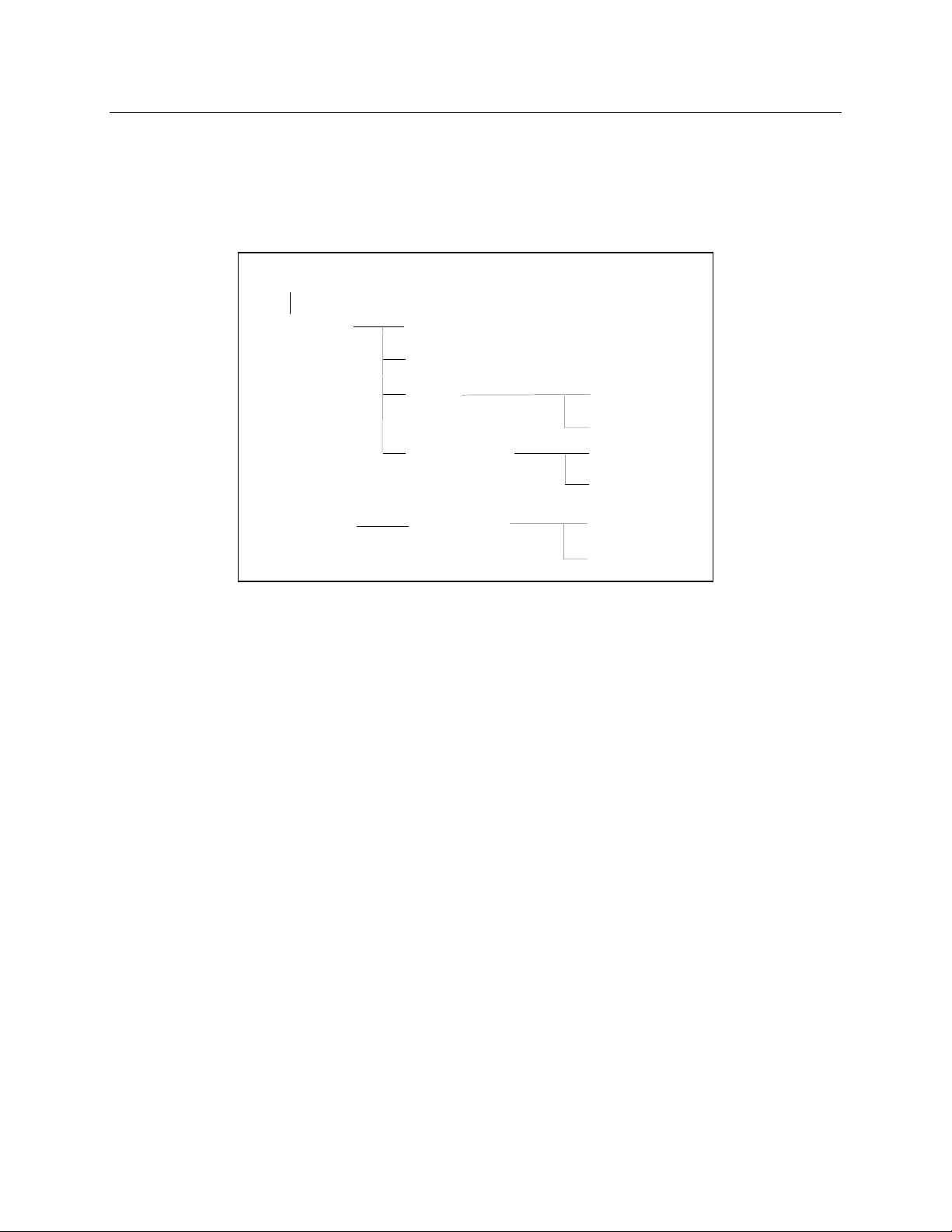
The SCPI Command Tree
As previously explained, the basic SCPI communication method involves sending one or more properly
formatted commands from the SCPI command tree to the instrument as program messages. The
following figure shows a portion of a subsystem command tree, from which you access the commands
located along the various paths (you can see the complete tree in appendix A).
ROO
:OUTPut
:STATus
[:STATe]
:COUPlin
:DFI
:PROTection
:OPERation
[:STATe]
:SOURce
:CLEar
:DELay
[:EVEN]
:CONDition?
?
Figure 2-1. Partial Command Tree
The Root Level
Note the location of the ROOT node at the top of the tree. Commands at the root level are at the top level
of the command tree. The SCPI interface is at this location when:
u the ac source is powered on
u a device clear (DCL) is sent to the ac source
u the SCPI interface encounters a message terminator
u the SCPI interface encounters a root specifier
Active Header Path
In order to properly traverse the command tree, you must understand the concept of the active header
path. When the ac source is turned on (or under any of the other conditions listed above), the active path
is at the root. That means the SCPI interface is ready to accept any command at the root level, such as
OUTPut or STATe.
If you enter OUTPut, the active header path moves one colon to the right . The interface is now ready to
accept :STATe, :COUPling, :DFI, or :PROTection as the next header. You must include the colon,
because it is required between headers.
If you now enter :PROTection, the active path again moves one colon to the right. The interface is now
ready to accept either :CLEar or :DELay as the next header.
18
Page 19

Introduction to Programming - 2
If you now enter :CLEar, you have reached the end of the command string. The active header path
remains at :CLEar. If you wished, you could have entered :CLEar;DELay 20 and it would be accepted as
a compound message consisting of:
OUTPut:PROTection:CLEAr and
OUTPut:PROTection:DELay 20.
The entire message would be:
OUTPut:PROTection:CLEar;DELay 20
The message terminator after DELay 20 returns the path to the root.
The Effect of Optional Headers
If a command includes optional headers, the interface assumes they are there. For example, if you enter
OUTPut OFF, the interface recognizes it as OUTPut:STATe OFF. This returns the active path to the root
(:OUTPut). But if you enter |OUTPut:STATe OFF,| then the active path remains at :STATe. This allows
you to send
OUTPut:STATe OFF;PROTection:CLEar
in one message. If you tried to send
OUTPut OFF;PROTection:CLEar
the header path would return to :OUTPut instead of :PROTection.
The optional header [SOURce] precedes the current, frequency, function, phase, pulse, list, and voltage
subsystems. This effectively makes :CURRent, :FREQuency, :FUNCtion, :PHASe, :PULse, :LIST, and
:VOLTage root-level commands.
Moving Among Subsystems
In order to combine commands from different subsystems, you need to be able to restore the active path
to the root. You do this with the root specifier (:). For example, you could clear the output protection and
check the status of the Operation Condition register as follows:
OUTPut:PROTection:CLEAr
STATus:OPERation:CONDition?
Because the root specifier resets the command parser to the root, you can use the root specifier and do
the same thing in one message:
OUTPut:PROTection:CLEAr;:STATus:OPERation:CONDition?
The following message shows how to combine commands from different subsystems as well as within the
same subsystem:
VOLTage:LEVel 70;PROTection 80;:CURRent:LEVel 3;PROTection:STATe ON
Note the use of the optional header LEVel to maintain the correct path within the voltage and current
subsystems and the use of the root specifier to move between subsytems.
NOTE: The "Enhanced Tree Walking Implementation" given in appendix A of the IEEE 488.2
standard is not implemented in the ac source.
19
Page 20

2 - Introduction to Programming
Including Common Commands
You can combine common commands with system commands in the same message. Treat the common
command as a message unit by separating it with a semicolon (the message unit separator). Common
commands do not affect the active header path; you may insert them anywhere in the message.
VOLTage:TRIGger 7.5;INITialize;*TRG
OUTPut OFF;*RCL 2;OUTPut ON
Using Queries
Observe the following precautions with queries:
u Set up the proper number of variables for the returned data.
u Read back all the results of a query before sending another command to the ac source. Otherwise
a Query Interrupted error will occur and the unreturned data will be lost.
Coupled Commands
When commands are coupled it means that the value sent by one command is affected by the settings of
the other commands. The following commands are coupled in the ac source:
u the voltage, voltage offset, and function shape commands
u the step, pulse, and list commands that control output voltages, voltage offsets, and function
shapes
u the pulse commands that program the width, duty cycle, period, and the hold parameter
u the voltage range and current limit commands in some ac source models
As explained later in Chapter 4, the order in which data is sent by these coupled commands can be
important when more than one parameter is changed.
Structure of a SCPI Message
SCPI messages consist of one or more message units ending in a message terminator. The terminator is
not part of the syntax, but implicit in the way your programming language indicates the end of a line (such
as a newline or end-of-line character).
The Message Unit
The simplest SCPI command is a single message unit consisting of a command header (or keyword)
followed by a message terminator.
ABORt<newline>
VOLTage?<newline>
The message unit may include a parameter after the header. The parameter usually is numeric, but it can
be a string:
VOLTage 20<newline>
VOLTage MAX<newline>
20
Page 21
Introduction to Programming - 2
g
y
Message Terminator
CURR?
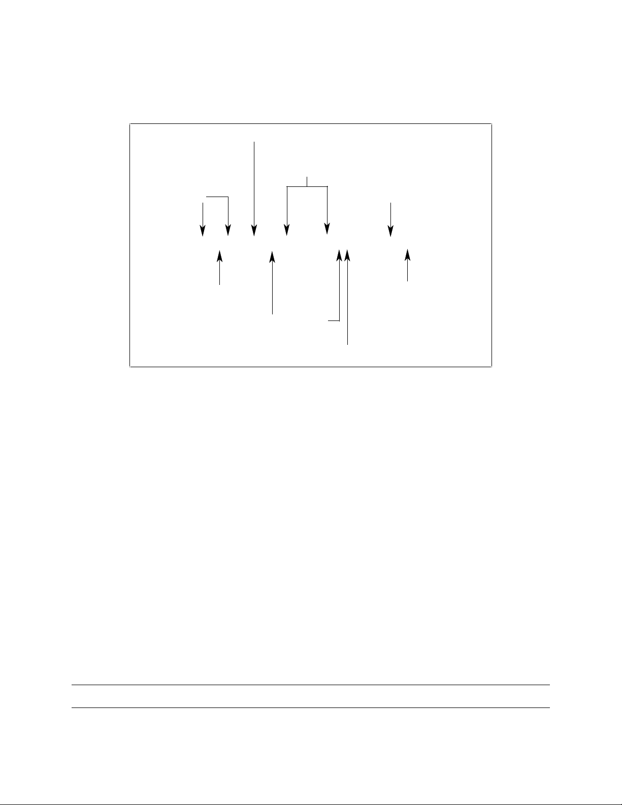
Combining Message Units
The following command message is briefly described here, with details in subsequent paragraphs.
Data
Message Unit
Headers
VOLT:LEV 80
Header Separator
Messa
e Unit Separators
Figure 2-2. Command Message Structure
The basic parts of the above message are:
Message Component Example
Headers
Header Separator
Data
Data Separator
Message Units
Message Unit Separator
Root Specifier
Query Indicator
Message Terminator
VOLT LEV PROT CURR
The colon in VOLT:LEV
8088
The space in VOLT 80 and PROT 88
VOLT:LEV 80 PROT 88 CURR?
The semicolons in VOLT:LEV 80; and PROT 88;
The colon in PROT 88;:CURR?
The question mark in CURR?
The <NL> (newline) indicator. Terminators are not part of the SCPI syntax
;
PROT 88
Root Specifier
Indicator
Quer
;
:
<NL>
Headers
Headers are instructions recognized by the ac source. Headers (which are sometimes known as
"keywords") may be either in the long form or the short form.
Long Form
Short Form
The SCPI interface is not sensitive to case. It will recognize any case mixture, such as TRIGGER, Trigger,
TRIGger.
NOTE: Short form headers result in faster program execution.
The header is completely spelled out, such as VOLTAGE, STATUS, and DELAY.
The header has only the first three or four letters, such as VOLT, STAT, and DEL.
21
Page 22

2 - Introduction to Programming
Header
Convention
Header
Separator
Optional
Headers
In the command descriptions in Chapter 3 of this manual, headers are emphasized with
boldface type. The proper short form is shown in upper-case letters, such as DELay.
If a command has more than one header, you must separate them with a colon
(VOLT:PROT OUTPut:RELay:POLarity).
The use of some headers is optional. Optional headers are shown in brackets, such as
OUTPut[:STATe] ON. As previously explained under "The Effect of Optional Headers", if
you combine two or more message units into a compound message, you may need to
enter the optional header.
Query Indicator
Following a header with a question mark turns it into a query (VOLTage?, VOLTage:PROTection?). If a
query contains a parameter, place the query indicator at the end of the last header
(VOLTage:PROTection? MAX).
Message Unit Separator
When two or more message units are combined into a compound message, separate the units with a
semicolon (STATus:OPERation?;QUEStionable?).
Root Specifier
When it precedes the first header of a message unit, the colon becomes the root specifier. It tells the
command parser that this is the root or the top node of the command tree. Note the difference between
root specifiers and header separators in the following examples:
OUTPut:PROTection:DELay .1
:OUTPut:PROTection:DELay .1
OUTPut:PROTection:DELay .1;:VOLTage 12.5
All colons are header separators
Only the first colon is a root specifier
Only the third colon is a root specifier
NOTE: You do not have to precede root-level commands with a colon; there is an implied colon in
front of every root-level command.
Message Terminator
A terminator informs SCPI that it has reached the end of a message. Three permitted messages
terminators are:
u newline (<NL>), which is ASCII decimal 10 or hex 0A.
u end or identify (<END>)
u both of the above (<NL><END>).
In the examples of this guide, there is an assumed message terminator at the end of each message. If the
terminator needs to be shown, it is indicated as <NL> regardless of the actual terminator character.
22
Page 23

Introduction to Programming - 2
SCPI Data Formats
All data programmed to or returned from the ac source is ASCII. The data may be numerical or character
string.
Numerical Data Formats
Symbol Data Form
Talking Formats
<NR1>
<NR2>
<NR3>
<Bool>
<Nrf>
<Nrf+>
<Bool>
Digits with an implied decimal point assumed at the right of the least-significant digit.
Examples: 273
Digits with an explicit decimal point. Example: .0273
Digits with an explicit decimal point and an exponent. Example: 2.73E+2
Boolean Data. Example: 0 | 1 or OFF | ON (0 = OFF; 1 = ON)
Listening Formats
Extended format that includes <NR1>, <NR2> and <NR3>. Examples: 273273. 2.73E2
Expanded decimal format that includes <NRf> and MINMAX. Examples: 273 73.2 .73E2
MAX. MIN and MAX are the minimum and maximum limit values that are implicit in the
range specification for the parameter.
Boolean Data. Example: 0 | 1
Suffixes and Multipliers
Class Suffix Unit Unit with Multiplier
Current A ampere MA (milliampere)
Amplitude V volt MV (millivolt)
Time S second MS (millisecond)
Frequency HZ Hertz KHZ (kilohertz)
Common Multipliers
1E3 K kilo
1E-3 M milli
1E-6 U micro
Character Data
Character strings returned by query statements may take either of the following forms, depending on the
length of the returned string:
<CRD>
<AARD>
<SRD>
Character Response Data. Permits the return of character strings.
Arbitrary ASCII Response Data. Permits the return of undelimited 7-bit ASCII. This data type
has an implied message terminator.
String Response Data. Returns string parameters enclosed in double quotes.
23
Page 24

2 - Introduction to Programming
System Considerations
The remainder of this chapter addresses some system issues concerning programming. These are ac
source addressing and the use of the following types of GPIB system interfaces:
u HP Vectra PC controller with Agilent 82335A GPIB Interface Command Library
u IBM PC controller with National Instruments GPIB-PCII Interface/Handler
u Agilent controller with Agilent BASIC Language System
Assigning the GPIB Address in Programs
The ac source address cannot be set remotely. It must be set from the front panel. Once the address is
set, you can assign it inside programs. The following examples assume that the GPIB select code is 7,
and the ac source will be assigned to the variable ACS.
1070 ACS=706 ! Agilent 82335A Interface
1070 ASSIGN @ACS TO 706 ! Agilent BASIC Interface
For systems using the National Instruments DOS driver, the address is specified in the software
configuration program (IBCONFIG.EXE) and assigned a symbolic name. The address then is referenced
only by this name within the application program (see the National Instruments GPIB documentation).
Types of DOS Drivers
The Agilent 82335A and National Instruments GPIB are two popular DOS drivers. Each is briefly
described here. See the software documentation supplied with the driver for more details.
Agilent 82335A Driver
For GW-BASIC programming, the GPIB library is implemented as a series of subroutine calls. To access
these subroutines, your application program must include the header file SETUP.BAS, which is part of the
DOS driver software.
SETUP.BAS starts at program line 5 and can run up to line 999. Your application programs must begin at
line 1000. SETUP.BAS has built-in error checking routines that provide a method to check for GPIB errors
during program execution. You can use the error-trapping code in these routines or write your own code
using the same variables as used by SETUP.BAS.
National Instruments GPIB Driver
Your program must include the National Instruments header file DECL.BAS. This contains the initialization
code for the interface. Prior to running any applications programs, you must set up the interface with the
configuration program (IBCONF.EXE).
Your application program will not include the ac source symbolic name and GPIB address. These must
be specified during configuration (when you run IBCONF.EXE). Note that the primary address range is
from 0 to 30 but any secondary address must be specified in the address range of 96 to 126. The
instrument expects a message termination on EOI or line feed, so set EOI w/last byte of Write. It is also
recommended that you set Disable Auto Serial Polling.
All function calls return the status word IBSTA%, which contains a bit (ERR) that is set if the call results in
an error. When ERR is set, an appropriate code is placed in variable IBERR%. Be sure to check IBSTA%
after every function call. If it is not equal to zero, branch to an error handler that reads IBERR% to extract
the specific error.
24
Page 25

Introduction to Programming - 2
Error Handling
If there is no error-handling code in your program, undetected errors can cause unpredictable results. This
includes "hanging up" the controller and forcing you to reset the system. Both of the above DOS drivers
have routines for detecting program execution errors.
Important Use error detection after every call to a subroutine.
Agilent BASIC Controllers
The Agilent BASIC Programming Language provides access to GPIB functions at the operating system
level. This makes it unnecessary to have the header files required in front of DOS applications programs.
Also, you do not have to be concerned about controller "hangups" as long as your program includes a
timeout statement. Because the ac source can be programmed to generate SRQ on errors, your program
can use an SRQ service routine for decoding detected errors. The detectable errors are listed in Appendix
C.
25
Page 26

Page 27

3
Language Dictionary
Introduction
This section gives the syntax and parameters for all the IEEE 488.2 SCPI commands and the Common
commands used by the ac sources when operating in Normal mode. It is assumed that you are familiar
with the material in Chapter 2 "Introduction to Programming". Because the SCPI syntax remains the same
for all programming languages, the examples given for each command are generic.
Syntax Forms
Parameters
Models
Phases
Related
Commands
Order of
Presentation
Syntax definitions use the long form, but only short form headers (or "keywords")
appear in the examples. Use the long form to help make your program selfdocumenting.
Most commands require a parameter and all queries will return a parameter.The range
for a parameter may vary according to the model of ac source. Parameters for all
models are listed in the Specifications table in the User’s Guide.
If a command only applies to specific models, those models are listed in the <Model>
Only entry. If there is no <Model> Only entry, the command applies to all models.
If a command can apply to individual phases of an , the entry Phase Selectable will
appear in the command description.
Where appropriate, related commands or queries are included. These are listed
because they are either directly related by function, or because reading about them will
clarify or enhance your understanding of the original command or query.
The dictionary is organized as follows:
u Subsystem commands, arranged by subsystem
u IEEE 488.2 common commands
27
Page 28

3 - Language Dictionary
Subsystem Commands
Subsystem commands are specific to functions. They can be a single command or a group of
commands. The groups are comprised of commands that extend one or more levels below the root. The
description of common commands follows the description of the subsystem commands.
The subsystem command groups are listed in alphabetical order and the commands within each
subsystem are grouped alphabetically under the subsystem. Commands followed by a question mark (?)
take only the query form. When commands take both the command and query form, this is noted in the
syntax descriptions.
You will find the subsystem command groups discussed on the following pages:
Subsystem Page
Calibration Subsystem 29
Display Subsystem 34
Instrument Subsystem 35
Measurement Subsystem (Arrays) 37
Measurement Subsystem (Current) 42
Measurement Subsystem (Frequency) 48
Measurement Subsystem (Power) 49
Measurement Subsystem (Voltage) 52
Output Subsystem 55
Sense Subsystem 60
Source Subsystem (Current) 62
Source Subsystem (Frequency) 65
Source Subsystem (Function) 68
Source Subsystem (List) 71
Source Subsystem (Phase) 80
Source Subsystem (Pulse) 82
Source Subsystem (Voltage) 85
Status Subsystem 94
System Commands 102
Trace Subsystem 105
Trigger Subsystem 107
Common Commands 113
28
Page 29

Language Dictionary - 3
Calibration Subsystem Commands
The commands in this subsystem allow you to do the following:
u Enable and disable the calibration mode
u Change the calibration password
u Calibrate the current and voltage output levels, and store new calibration constants in nonvolatile
memory.
Subsystem Syntax
CALibrate
:CURRent
:AC Begin ac current programming calibration sequence
:MEASure Begin current measurement calibration sequence
:DATA <n> Input a calibration measurement
:IMPedance Begin output impedance calibration sequence
:LEVel <level> Advance to next calibration step (P1 | P2 | P3 | P4)
:PASSword <n> Set calibration password
:PWM
:FREQuency <n> Trim pulse width modulator frequency
:RAMP <n> Trim pulse width modulator ramp
:SAVE Save new cal constants in non-volatile memory
:STATE <bool> [,<n>] Enable or disable calibration mode
:VOLTage
:AC Begin ac voltage calibration sequence
:DC Begin dc voltage calibration sequence
:OFFSet Begin offset voltage calibration sequence
:PROTection Begin voltage protection calibration sequence
:RTIMe Begin realtime voltage calibration sequence
CALibrate:CURRent:AC
Phase Selectable
This command can only be used in the calibration mode. It initiates the calibration of the ac current limit
and metering circuits.
Command Syntax
Parameters
Examples
Related Commands
CALibrate:CURRent:AC
None
CAL:CURR:AC
CAL:STAT CAL:SAV CAL:LEV
29
Page 30

3 - Language Dictionary
CALibrate:CURRent:MEASure
Agilent 6811B, 6812B, 6813B, 6843A Only
This command is used to initiate the calibration of the current metering circuits and the peak current limit
circuits. It can only be used in the calibration mode.
Command Syntax
Parameters
Examples
Related Commands
CALibrate:CURRent:MEASure
None
CAL:CURR:MEAS
CAL:STAT CAL:SAV CAL:LEV
CALibrate:DATA
Phase Selectable
This command is only used in calibration mode. It enters a calibration value that you obtain by reading an
external meter. You must first select a calibration level (with CALibrate:LEVel) for the value being entered.
These constants are not stored in nonvolatile memory until they are saved with CALibrate:SAVE. If
CALibrate:STATE OFF is programmed without a CALibrate:SAVE, the previous calibration constants are
restored.
Command Syntax
Parameters
Examples
Related Commands
CALibrate:DATA <NRf>
<external reading>
A
Unit
(amperes)
CAL:DATA 3222.3 MA CAL:DATA 5.000
CAL:STAT CAL:SAV
CALibrate:IMPedance
Agilent 6811B, 6812B, 6813B, 6843A Only
This command can only be used in calibration mode. It calibrates the output impedance circuits. The
automatically performs the calibration and stores the impedance constant in nonvolatile memory.
CALibrate:IMPedance is a sequential command that takes several seconds to complete.
Command Syntax
Parameters
Examples
Related Commands
CALibrate:IMPedance
None
CAL:IMP
CAL:STAT CAL:SAV
CALibrate:LEVel
Phase Selectable
This command can only be used in calibration mode. It is used to advance to the next state in the
calibration sequence.
Command Syntax
Parameters
Examples
Related Commands
CALibrate:LEVel <level>
P1 | P2 | P3 | P4
CAL:LEV P2
CAL:STAT CAL:SAV
30
Page 31

Language Dictionary - 3
CALibrate:PASSword
This command can only be used in calibration mode. It allows you to change the calibration password. A
new password is automatically stored in nonvolatile memory and does not have to be stored with
CALibrate:SAVE. If the password is set to 0, password protection is removed and the ability to enter the
calibration mode is unrestricted.
Command Syntax
Parameters
Examples
Related Commands
CALibrate:PASSword <NRf>
0 (default)
CAL:PASS 6812 CAL:PASS 02.1997
CAL:STAT
CALibrate:PWM:FREQuency
Agilent 6811B, 6812B, 6813B Only
This command is only used during manufacture or repair. It trims the switching frequency of the power
output stages. The numbers from 0 to 7 are internally mapped to 8 discrete frequencies.
Command Syntax
Parameters
Examples
Query Syntax
Returned Parameters
Related Commands
CALCulate:PWM:FREQuency <NRf>
0 through 7
CAL:PWM:FREQ 1
CALibrate:PWM:FREQuency?
<NR1>
CAL:PWM:RAMP
CALibrate:PWM:RAMP
Agilent 6811B, 6812B, 6813B, Only
This command modulates the slope of voltage ramp driving the power output stages. Varying the ramp
affects the harmonic distortion of the output. The argument is a number from 0 to 255. This command is
only used during manufacture or repair of the .
Command Syntax
Parameters
Examples
Query Syntax
Returned Parameters
Related Commands
CALCulate:PWM:RAMP <NRf>
0 through 255
CAL:PWM:RAMP 100
CALibrate:PWM:RAMP?
<NR1>
CAL:PWM:FREQ
CALibrate:SAVE
This command can only be used in calibration mode. It saves any new calibration constants (after a
current or voltage calibration procedure has been completed) in nonvolatile memory.
Command Syntax
Parameters
Examples
Related Commands
CALibrate:SAVE
None
CAL:SAVE
CAL:CURR CAL:VOLT CAL:STAT
31
Page 32

3 - Language Dictionary
CALibrate:STATe
This command enables and disables calibration mode. The calibration mode must be enabled before the
will accept any other calibration commands. The first parameter specifies the enabled or disabled state.
The second parameter is the password. It is required if the calibration mode is being enabled and the
existing password is not 0. If the password is not entered or is incorrect, an error is generated and the
calibration mode remains disabled. The query statement returns only the state, not the password.
Whenever the calibration state is changed from enabled to disabled, any new calibration constants are
lost unless they have been stored with CALibrate:SAVE.
Command Syntax
Parameters
*RST Value
Examples
Query Syntax
Returned Parameters
Related Commands
CALibrate:STATe <bool> [,<NRf>]
0 | 1 | OFF | ON [,<password>]
OFF
CAL:STAT 1,6812 CAL:STAT OFF
CALibrate:STATe?
<NR1>
CAL:PASS CAL:SAVE
CALibrate:VOLTage:AC
Phase Selectable
This command can only be used in calibration mode. It initiates the calibration of the ac voltage
programming and metering circuits.
Command Syntax
Parameters
Examples
Related Commands
CALibrate:VOLTage:AC
None
CAL:VOLT:AC
CAL:SAVE CAL:STAT
CALibrate:VOLTage:DC
Agilent 6811B, 6812B, 6813B, Only
This command can only be used in calibration mode. It initiates the calibration of the dc voltage
programming circuits.
Command Syntax
Parameters
Examples
Related Commands
32
CALibrate:VOLTage:DC
None
CAL:VOLT:DC
CAL:SAVE CAL:STAT
Page 33

Language Dictionary - 3
CALibrate:VOLTage:OFFSet
Agilent 6811B, 6812B, 6813B, Only
This command can only be used in calibration mode. It initiates the calibration of the offset voltage
programming circuits.
Command Syntax
Parameters
Examples
Related Commands
CALibrate:VOLTage:OFFSet
None
CAL:VOLT:OFFS
CAL:SAVE CAL:STAT CAL:LEV
CALibrate:VOLTage:PROTection
This command can only be used in calibration mode. It calibrates the overvoltage protection (OV) circuit.
The automatically performs the calibration and stores the new OV constant in nonvolatile memory.
CALibrate:VOLTage:PROTection is a sequential command that takes several seconds to complete.
Command Syntax
Parameters
Examples
Related Commands
CALibrate:VOLTage:PROTection
None
CAL:VOLT:PROT
CAL:SAVE CAL:STAT
CALibrate:VOLTage:RTIMe
Agilent 6843A Only
This command can only be used in calibration mode. It calibrates the realtime voltage programming
circuit.
Command Syntax
Parameters
Examples
Related Commands
CALibrate:VOLTage:RTIMe
None
CAL:VOLT:RTIM
CAL:SAVE CAL:STAT
33
Page 34

3 - Language Dictionary
Display Subsystem Commands
This subsystem programs the front panel display of the ac source.
Subsystem Syntax
DISPlay
[:WINDow]
[:STATe] <bool> Enable/disable front panel display
:MODE <mode> Set display mode (NORMal | TEXT)
:TEXT
[:DATA] <display string> Set text displayed in text mode
DISPlay
This command turns the front panel display on and off. It does not affect the annunciators.
Command Syntax
Parameters
*RST Value
Examples
Query Syntax
Returned Parameters
Related Commands
DISPlay[:WINDow]:STATe <bool>
0 | 1 | OFF | ON
ON
DISP:STAT 1, DISP:STAT OFF
DISPlay[:WINDow]:STATe?
0 | 1
DISP:MODE DISP:TEXT
DISPlay:MODE
This command sets the display to show either normal instrument functions, or to show a text message.
Text messages are defined with DISPlay:TEXT:DATA.
Command Syntax
Parameters
*RST Value
Examples
Query Syntax
Returned Parameters
Related Commands
DISPlay[:WINDow]:MODE <mode>
NORMal | TEXT
NORMal
DISP:MODE TEXT
DISPlay[:WINDow]:MODE?
<CRD>
DISP DISP:TEXT
DISPlay:TEXT
This command sets the character string that is displayed when the display mode is set to TEXT. The
argument is a quoted string limited to upper case alpha characters and numbers. The display is capable
of showing up to 14 characters. If the string exceeds the display capacity, it will be truncated.
34
Command Syntax
Parameters
*RST Value
Examples
Query Syntax
Returned Parameters
Related Commands
DISPlay[:WINDow]:TEXT[:DATA] <display_string>
<display_string>
null string
DISP:TEXT “DO TEST1”
DISPlay[:WINDow]:TEXT?
<SRD> (the last programmed string)
DISP DISP:MODE
Page 35

Language Dictionary - 3
Instrument Subsystem
This subsystem programs the three-phase output capability of the Agilent 6834B .
Subsystem Syntax
INSTrument
:COUPle <phase> Couple all phases for programming (ALL | NONE)
:NSELect <n> Select the output phase to program (1 | 2 | 3)
:SELect <output> Select the output phase to program (OUTP1 | OUTP2 | OUTP3)
INSTrument:COUPle
Agilent 6834B Only
In a three-phase power source it is convenient to set parameters of all three output phases simultaneously
with one programming command. When INST:COUP ALL is programmed, sending a command to any
phase will result in that command being sent to all three phases.
NOTE: INSTrument:COUPle only affects the operation of subsequent commands. It does not by
itself immediately affect the ’s output. The commands that are affected by
INSTrument:COUPle are those with the designation: Phase Selectable.
INSTrument:COUPle has no affect on queries. There is no way to query more than one phase with a
single command. Directing queries to individual phases is done with INSTrument:NSELect.
Command Syntax
Parameters
*RST Value
Examples
Query Syntax
Returned Parameters
Related Commands
INSTrument:COUPle <phase>
ALL | NONE
ALL
INST:COUP ALL
INSTrument:COUPle?
<CRD>
INST:NSEL
35
Page 36

3 - Language Dictionary
INSTrument:NSELect
INSTrument:SELect
Agilent 6834B Only
These commands allow the selection of individual outputs in a three-phase model for subsequent
commands or queries. Their operation is dependent on the setting of INSTrument:COUPle. If INST:COUP
NONE is programmed, then the phase selectable commands are sent only to the particular output phase
set by INSTrument:NSELect. If INST:COUP ALL is programmed, then all commands are sent to all three
output phases.
INSTrument:NSELect selects the phase by its number, while INSTrument:SELect references it by name.
These commands also select which output phase returns data when a query is sent.
Command Syntax
Parameters
*RST Value
Examples
Query Syntax
Returned Parameters
Related Commands
INSTrument:NSELect <NR1>
INSTrument:SELect <output>
For INST:NSEL 1 | 2 | 3
For INST:SEL OUTPut1 | OUTPut2 | OUTPut3
1 or OUTPut1
INST:NSEL 3 INST:SEL OUTP1
INSTrument:NSELect?
<NR1>
INST:COUP
36
Page 37

Language Dictionary - 3
Measurement Subsystem (Arrays)
This subsystem lets you retrieve arrays containing measurements data. Only current and voltage
measurements are stored in an array. Two measurement commands are available: MEASure and FETCh.
MEASure triggers the acquisition of new data before returning the readings from the array. FETCh returns
previously acquired data from the array.
Individual outputs of a three-phase source are specified by the setting of INSTrument:NSELect.
Subsystem Syntax
MEASure | FETCh
:ARRay
:CURRent
[:DC]? Returns the digitized instantaneous current
:HARMonic
[:AMPLitude]? Returns amplitudes of the first 50 harmonics
:PHASe? Returns phase angles of the first 50 harmonics
:NEUTral
[:DC]? Returns the neutral digitized instantaneous current (3-phase only)
:HARMonic
[:AMPLitude]? Returns neutral current harmonic amplitude
:PHASe? Returns neutral current harmonic phase
:VOLTage
[:DC]? Returns the digitized instantaneous voltage
:HARMonic
[:AMPLitude]? Returns amplitudes of the first 50 harmonics
:PHASe? Returns phase angles of the first 50 harmonics
MEASure:ARRay:CURRent?
FETCh:ARRay:CURRent?
Phase Selectable
These queries return an array containing the instantaneous output current in amperes. The output voltage
and current are digitized whenever a measure command is given or whenever an acquire trigger occurs. If
digitization is caused by a measure command, the time interval between samples is determined by the
output frequency. For frequencies greater than 45Hz, the time interval is 25 microseconds. If digitization is
caused by an acquire trigger, the time interval is set by SENSe:SWEep:TINTerval, and the position of the
trigger relative to the beginning of the data buffer is determined by SENSe:SWEep:OFFSet:POINts.
Query Syntax
Parameters
Examples
Returned Parameters
Related Commands
MEASure:ARRay:CURRent[:DC]?
FETCh:ARRay:CURRent[:DC]?
None
MEAS:ARR:CURR? FETC:ARR:CURR?
4096 NR3 values
MEAS:ARR:VOLT?
37
Page 38

3 - Language Dictionary
MEASure:ARRay:CURRent:HARMonic?
FETCh:ARRay:CURRent:HARMonic?
Phase Selectable
These queries return an array of harmonic amplitudes of output current in rms amperes.
The first value returned is the dc component, the second value is the fundamental frequency, and so on
up to the 50th harmonic. Harmonic orders can be measured up to the fundamental measurement
bandwidth of the measurement system, which is 12.6kHz. Thus, the maximum harmonic that can be
measured is dependent on the output frequency. Any harmonics that represent frequencies greater than
12.6kHz are returned as 0.
Query Syntax
Parameters
Examples
Returned Parameters
Related Commands
MEASure:ARRay:CURRent:HARMonic[:AMPLitude]?
FETCh:ARRay:CURRent:HARMonic[:AMPLitude]?
None
MEAS:ARR:CURR:HARM? FETC:ARR:CURR:HARM?
51 NR3 values
MEAS:ARR:VOLT:HARM? MEAS:ARR:CURR:HARM:PHAS?
MEASure:ARRay:CURRent:HARMonic:PHASe?
FETCh:ARRay:CURRent:HARMonic:PHASe?
Phase Selectable
These queries return an array of harmonic phases of output current in degrees, referenced to the positive
zero crossing of the fundamental component.
The first value returned is the dc component (always returned as 0 degrees phase) , the second value is
the fundamental frequency, and so on up to the 50th harmonic. Harmonic orders can be measured up to
the fundamental measurement bandwidth of the measurement system, which is 12.6kHz. Thus the
maximum harmonic that can be measured is dependent on the output frequency. Any harmonics that
represent frequencies greater than 12.6kHz are returned as 0.
Query Syntax
Parameters
Examples
Returned Parameters
Related Commands
MEASure:ARRay:CURRent:HARMonic:PHASe? <NRf>
FETCh:ARRay:CURRent:HARMonic:PHASe? <NRf>
None
MEAS:ARR:CURR:HARM:PHAS?
FETC:ARR:CURR:HARM:PHAS?
51 NR3 values
MEAS:ARR:VOLT:HARM:PHAS? MEAS:ARR:CURR:HARM?
38
Page 39

Language Dictionary - 3
MEASure:ARRay:CURRent:NEUTral?
FETCh:ARRay:CURRent:NEUTral?
Agilent 6834B Only
These queries return an array containing the instantaneous output current of the neutral output terminal in
amperes.
The output voltage and current are digitized whenever a measure command is given or whenever an
acquire trigger occurs. If digitization is caused by a measure command, the time interval between samples
is determined by the output frequency. For frequencies greater than 45Hz, the time interval is 25
microseconds. If digitization is caused by an acquire trigger, the time interval is set by
SENSe:SWEep:TINTerval, and the position of the trigger relative to the beginning of the data buffer is
determined by SENSe:SWEep:OFFSet:POINts.
Query Syntax
Parameters
Examples
Returned Parameters
MEASure:ARRay:CURRent:NEUTral[:DC]?
FETCh:ARRay:CURRent:NEUTral[:DC]?
None
MEAS:ARR:CURR:NEUT? FETC:ARR:CURR:NEUT?
4096 NR3 values
MEASure:ARRay:CURRent:NEUTral:HARMonic?
FETCh:ARRay:CURRent:NEUTral:HARMonic?
Agilent 6834B Only
These queries return an array of harmonic amplitudes of output current of the neutral output terminal in
rms amperes.
The first value returned is the dc component, the second value is the fundamental frequency, and so on
up to the 50th harmonic. Harmonic orders can be measured up to the fundamental measurement
bandwidth of the measurement system, which is 12.6kHz. Thus, the maximum harmonic that can be
measured is dependent on the output frequency. Any harmonics that represent frequencies greater than
12.6kHz are returned as 0.
Query Syntax
Parameters
Examples
Returned Parameters
Related Commands
MEASure:ARRay:CURRent:NEUTral:HARMonic[:AMPLitude]?
FETCh:ARRay:CURRent:NEUTral:HARMonic[:AMPLitude]?
None
MEAS:ARR:CURR:NEUT:HARM?
FETC:ARR:CURR:NEUT:HARM?
51 NR3 values
MEAS:ARR:CURR:NEUT:HARM:PHAS?
39
Page 40

3 - Language Dictionary
MEASure:ARRay:CURRent:NEUTral:HARMonic:PHASe?
FETCh:ARRay:CURRent:NEUTral:HARMonic:PHASe?
Agilent 6834B Only
These queries return an array of harmonic phases of output current of the neutral output terminal in
degrees, referenced to the positive zero crossing of the fundamental component.
The first value returned is the dc component (always returned as 0 degrees phase) , the second value is
the fundamental frequency, and so on up to the 50th harmonic. Harmonic orders can be measured up to
the fundamental measurement bandwidth of the measurement system, which is 12.6kHz. Thus the
maximum harmonic that can be measured is dependent on the output frequency. Any harmonics that
represent frequencies greater than 12.6kHz are returned as 0.
Query Syntax
Parameters
Examples
Returned Parameters
Related Commands
MEASure:ARRay:CURRent:NEUTral:HARMonic:PHASe?
FETCh:ARRay:CURRent:NEUTral:HARMonic:PHASe?
None
MEAS:ARR:CURR:NEUT:HARM:PHAS?
FETC:ARR:CURR:NEUT:HARM:PHAS?
51 NR3 values
MEAS:ARR:CURR:NEUT:HARM?
MEASure:ARRay:VOLTage?
FETCh:ARRay:VOLTage?
Phase Selectable
These queries return an array containing the instantaneous output voltage in volts.
The output voltage and current are digitized whenever a measure command is given or whenever an
acquire trigger occurs. If digitization is caused by a measure command, the time interval between samples
is determined by the output frequency. For frequencies greater than 45Hz, the time interval is 25
microseconds. If digitization is caused by an acquire trigger, the time interval is set by
SENSe:SWEep:TINTerval, and the position of the trigger relative to the beginning of the data buffer is
determined by SENSe:SWEep:OFFSet:POINts.
Query Syntax
Parameters
Examples
Returned Parameters
Related Commands
MEASure:ARRay:VOLTage[:DC]?
FETCh:ARRay:VOLTage[:DC]?
None
MEAS:ARR:VOLT? FETC:ARR:VOLT?
4096 NR3 values
MEAS:ARR:CURR?
40
Page 41

Language Dictionary - 3
MEASure:ARRay:VOLTage:HARMonic?
FETCh:ARRay:VOLTage:HARMonic?
Phase Selectable
These queries return an array of harmonic amplitudes of output voltage in rms volts.
The first value returned is the dc component, the second value is the fundamental frequency, and so on
up to the 50th harmonic. Harmonic orders can be measured up to the fundamental measurement
bandwidth of the measurement system, which is 12.6kHz. Thus, the maximum harmonic that can be
measured is dependent on the output frequency. Any harmonics that represent frequencies greater than
12.6kHz are returned as 0.
Query Syntax
Parameters
Examples
Returned Parameters
Related Commands
MEASure:ARRay:VOLTage:HARMonic[:AMPLitude]?
FETCh:ARRay:VOLTage:HARMonic[:AMPLitude]?
None
MEAS:ARR:VOLT:HARM? FETC:ARR:VOLT:HARM?
51 NR3 values
MEAS:ARR:CURR:HARM? MEAS:ARR:VOLT:HARM:PHAS?
MEASure:ARRay:VOLTage:HARMonic:PHASe?
FETCh:ARRay:VOLTage:HARMonic:PHASe?
Phase Selectable
These queries return an array of harmonic phases of output voltage in degrees, referenced to the positive
zero crossing of the fundamental component.
The first value returned is the dc component (always returned as 0 degrees phase) , the second value is
the fundamental frequency, and so on up to the 50th harmonic. Harmonic orders can be measured up to
the fundamental measurement bandwidth of the measurement system, which is 12.6kHz. Thus the
maximum harmonic that can be measured is dependent on the output frequency. Any harmonics that
represent frequencies greater than 12.6kHz are returned as 0.
Query Syntax
Parameters
Examples
Returned Parameters
Related Commands
MEASure:ARRay:VOLTage:HARMonic:PHASe? <NRf>
FETCh:ARRay:VOLTage:HARMonic:PHASe? <NRf>
None
MEAS:ARR:VOLT:HARM:PHAS?
FETC:ARR:VOLT:HARM:PHAS?
51 NR3 values
MEAS:ARR:CURR:HARM:PHAS? MEAS:ARR:VOLT:HARM?
41
Page 42

3 - Language Dictionary
Measurement Subsystem (Current)
This subsystem programs the current measurement capability of the ac source. Two measurement
commands are available: MEASure and FETCh. MEASure triggers the acquisition of new measurement
data before returning a reading. FETCh returns a reading computed from previously acquired data.
Individual outputs of a three-phase source are specified by the setting of INSTrument:NSELect.
Subsystem Syntax
MEASure | FETCh
[:SCALar]
:CURRent
[:DC]? Returns dc component of the current
:AC? Returns ac rms current
:ACDC? Returns ac+dc rms current
:AMPLitude
:MAX? Returns peak current
:CREStfactor? Returns current crestfactor
:HARMonic
[:AMPLitude]? <n> Returns amplitude of the Nth harmonic of current
:PHASe? <n> Returns phase of the Nth harmonic of current
:THD? Returns % of total harmonic distortion of current
:NEUTral
[:DC]? Returns neutral dc current (3-phase only)
:AC? Returns neutral ac rms current (3-phase only)
:ACDC? Returns neutral ac+dc rms current (3-phase only)
:HARMonic
[:AMPLitude]? <n> Returns neutral current harmonic amplitude (3-phase only)
:PHASe? <n> Returns neutral current harmonic phase (3-phase only)
MEASure:CURRent?
FETCh:CURRent?
Phase Selectable
These queries return the dc component of the output current being sourced at the output terminals.
Query Syntax
Parameters
Examples
Returned Parameters
Related Commands
42
MEASure:[SCALar]:CURRent[:DC]?
FETCh:[SCALar]:CURRent[:DC]?
None
MEAS:CURR? FETC:CURR?
<NR3>
MEAS:VOLT? MEAS:CURR:AC?
Page 43

Language Dictionary - 3
MEASure:CURRent:AC?
FETCh:CURRent:AC?
Phase Selectable
These queries return the ac component rms current being sourced at the output terminals.
Query Syntax
Parameters
Examples
Returned Parameters
Related Commands
MEASure:[SCALar]:CURRent:AC?
FETCh:[SCALar]:CURRent:AC?
None
MEAS:CURR:AC? FETC:CURR:AC?
<NR3>
MEAS:VOLT:AC? MEAS:CURR?
MEASure:CURRent:ACDC?
FETCh:CURRent:ACDC?
Phase Selectable
These queries return the ac+dc rms current being sourced at the output terminals.
Query Syntax
Parameters
Examples
Returned Parameters
Related Commands
MEASure:[SCALar]:CURRent:ACDC?
FETCh:[SCALar]:CURRent:ACDC?
None
MEAS:CURR:ACDC? FETC:CURR:ACDC?
<NR3>
MEAS:VOLT:ACDC? MEAS:CURR:AMPL:MAX?
MEASure:CURRent:AMPLitude:MAXimum?
FETCh:CURRent:AMPLitude:MAXimum?
Phase Selectable
These queries return the absolute value of the peak current as sampled over one measurement
acquisition of 4096 data points.
Query Syntax
Parameters
Examples
Returned Parameters
Related Commands
MEASure:[SCALar]:CURRent:AMPLitude:MAXimum?
FETCh:[SCALar]:CURRent:AMPLitude:MAXimum?
None
MEAS:CURR:AMPL:MAX? FETC:CURR:AMPL:MAX?
<NR3>
MEAS:CURR:ACDC? MEAS:CURR:CRES?
43
Page 44

3 - Language Dictionary
MEASure:CURRent:CREStfactor?
FETCh:CURRent:CREStfactor?
Phase Selectable
These queries return the output current crest factor. This is the ratio of peak output current to rms output
current.
Query Syntax
Parameters
Examples
Returned Parameters
Related Commands
MEASure:[SCALar]:CURRent:CREStfactor?
FETCh:[SCALar]:CURRent:CRESfactor?
None
MEAS:CURR:CRES? FETC:CURR:CRES?
<NR3>
MEAS:CURR:ACDC? MEAS:CURR:AMPL:MAX?
MEASure:CURRent:HARMonic?
FETCh:CURRent:HARMonic?
Phase Selectable
These queries return the rms amplitude of the Nth harmonic of output current.
The parameter is the desired harmonic number. Queries sent with a value of 0 return the dc component. A
value of 1 returns the fundamental output frequency. Harmonic orders can be queried up to the
fundamental measurement bandwidth of the measurement system, which is 12.6kHz. Thus the maximum
harmonic that can be measured is dependent on the output frequency. Any harmonics that represent
frequencies greater than 12.6kHz are returned as 0.
Query Syntax
Parameters
Examples
Returned Parameters
Related Commands
MEASure:[SCALar]:CURRent:HARMonic[:AMPLitude]? <NRf>
FETCh:[SCALar]:CURRent:HARMonic[:AMPLitude]? <NRf>
0 to 50
MEAS:CURR:HARM? 3 FETC:CURR:HARM? 1
<NR3>
MEAS:CURR:HARM:PHAS? MEAS:CURR:HARM:THD?
44
Page 45

Language Dictionary - 3
MEASure:CURRent:HARMonic:PHASe?
FETCh:CURRent:HARMonic:PHASe?
Phase Selectable
These queries return the phase angle of the Nth harmonic of output current, referenced to the positive
zero crossing of the fundamental component.
The parameter is the desired harmonic number. Queries sent with a value of 0 return the dc component. A
value of 1 returns the fundamental output frequency. Harmonic orders can be queried up to the
fundamental measurement bandwidth of the measurement system, which is 12.6kHz. Thus the maximum
harmonic that can be measured is dependent on the output frequency. Any harmonics that represent
frequencies greater than 12.6kHz are returned as 0.
Query Syntax
Parameters
Examples
Returned Parameters
Related Commands
MEASure:[SCALar]:CURRent:HARMonic:PHASe? <NRf>
FETCh:[SCALar]:CURRent:HARMonic:PHASe? <NRf>
0 to 50
MEAS:CURR:HARM:PHAS? 3 FETC:CURR:HARM:PHAS? 1
<NR3>
MEAS:CURR:HARM? MEAS:CURR:HARM:THD?
MEASure:CURRent:HARMonic:THD?
FETCh:CURRent:HARMonic:THD?
Phase Selectable
These queries return the percentage of total harmonic distortion and noise in the output current.
Query Syntax
Parameters
Examples
Returned Parameters
Related Commands
MEASure:[SCALar]:CURRent:HARMonic:THD?
FETCh:[SCALar]:CURRent:HARMonic:THD?
None
MEAS:CURR:HARM:THD? FETC:CURR:HARM:THD?
<NR3>
MEAS:CURR:HARM? MEAS:CURR:HARM:PHAS?
MEASure:CURRent:NEUTral?
FETCh:CURRent:NEUTral?
Agilent 6834B Only
These queries return the dc current in the neutral output terminal of a three-phase ac source.
Query Syntax
Parameters
Examples
Returned Parameters
Related Commands
MEASure:[SCALar]:CURRent:NEUTral[:DC]?
FETCh:[SCALar]:CURRent:NEUTral[:DC]?
None
MEAS:CURR:NEUT? FETC:CURR:NEUT?
<NR3>
MEAS:CURR:NEUT:AC? MEAS:CURR:NEUT:ACDC?
45
Page 46

3 - Language Dictionary
MEASure:CURRent:NEUTral:AC?
FETCh:CURRent:NEUTral:AC?
Agilent 6834B Only
These queries return the ac rms current in the neutral output terminal of a three-phase ac source.
Query Syntax
Parameters
Examples
Returned Parameters
Related Commands
MEASure:[SCALar]:CURRent:NEUTral:AC?
FETCh:[SCALar]:CURRent:NEUTral:AC?
None
MEAS:CURR:NEUT:AC? FETC:CURR:NEUT:AC?
<NR3>
MEAS:CURR:NEUT? MEAS:CURR:NEUT:ACDC?
MEASure:CURRent:NEUTral:ACDC?
FETCh:CURRent:NEUTral:ACDC?
Agilent 6834B Only
These queries return the ac+dc rms current in the neutral output terminal of a three-phase .
Query Syntax
Parameters
Examples
Returned Parameters
Related Commands
MEASure:[SCALar]:CURRent:NEUTral:ACDC?
FETCh:[SCALar]:CURRent:NEUTral:ACDC?
None
MEAS:CURR:NEUT:ACDC? FETC:CURR:NEUT:ACDC?
<NR3>
MEAS:CURR:NEUT? MEAS:CURR:NEUT:AC?
MEASure:CURRent:NEUTral:HARMonic?
FETCh:CURRent:NEUTral:HARMonic?
Agilent 6834B Only
These queries return the rms amplitude of the Nth harmonic of current in the neutral output terminal of a
three-phase ac source.
The parameter is the desired harmonic number. Queries sent with a value of 0 return the dc component. A
value of 1 returns the fundamental output frequency. Harmonic orders can be queried up to the
fundamental measurement bandwidth of the measurement system, which is 12.6kHz. Thus the maximum
harmonic that can be measured is dependent on the output frequency. Any harmonics that represent
frequencies greater than 12.6kHz are returned as 0.
Query Syntax
Parameters
Examples
Returned Parameters
Related Commands
46
MEASure:[SCALar]:CURRent:NEUTral:HARMonic[:AMPLitude]? <NRf>
FETCh:[SCALar]:CURRent:NEUTral:HARMonic[:AMPLitude]? <NRf>
0 to 50
MEAS:CURR:NEUT:HARM? 3 FETC:CURR:NEUT:HARM? 1
<NR3>
MEAS:CURR:NEUT:HARM:PHAS?
Page 47

Language Dictionary - 3
MEASure:CURRent:NEUTral:HARMonic:PHASe?
FETCh:CURRent:NEUTral:HARMonic:PHASe?
Agilent 6834B Only
These queries return the phase angle of the Nth harmonic of current in the neutral output terminal of a
three-phase ac source, referenced to the positive zero crossing of the fundamental component.
The parameter is the desired harmonic number. Queries sent with a value of 0 return the dc component. A
value of 1 returns the fundamental output frequency. Harmonic orders can be queried up to the
fundamental measurement bandwidth of the measurement system, which is 12.6kHz. Thus the maximum
harmonic that can be measured is dependent on the output frequency. Any harmonics that represent
frequencies greater than 12.6kHz are returned as 0.
Query Syntax
Parameters
Examples
Returned Parameters
Related Commands
MEASure:[SCALar]:CURRent:NEUTral:HARMonic:PHASe? <NRf>
FETCh:[SCALar]:CURRent:NEUTral:HARMonic:PHASe? <NRf>
0 to 50
MEAS:CURR:NEUT:HARM:PHAS? 3
FETC:CURR:NEUT:HARM:PHAS? 1
<NR3>
MEAS:CURR:NEUT:HARM?
47
Page 48

3 - Language Dictionary
Measurement Subsystem (Frequency)
This subsystem programs the frequency measurement capability of the ac source. Two measurement
commands are available: MEASure and FETCh. MEASure triggers the acquisition of new measurement
data before returning a reading. FETCh returns a reading computed from previously acquired data.
Subsystem Syntax
MEASure | FETCh
[:SCALar]
:FREQuency? Returns the output frequency
MEASure:FREQuency?
FETCh:FREQuency?
This query returns the output frequency in Hertz.
Query Syntax
Parameters
Examples
Returned Parameters
MEASure:[SCALar]:FREQuency?
FETCh:[SCALar]:FREQuency?
None
MEAS:FREQ? FETC:FREQ?
<NR3>
48
Page 49

Language Dictionary - 3
Measurement Subsystem (Power)
This subsystem programs the power measurement capability of the ac source. Two measurement
commands are available: MEASure and FETCh. MEASure triggers the acquisition of new measurement
data before returning a reading. FETCh returns a reading computed from previously acquired data.
Individual outputs of a three-phase source are specified by the setting of INSTrument:NSELect.
Subsystem Syntax
MEASure | FETCh
[:SCALar]
:POWer
[:DC]? Returns the dc component of power
:AC
[:REAL]? Returns real power
:APParent? Returns VA
:REACtive? Returns VAR
:PFACtor? Returns power factor
:TOTal? Returns real 3-phase total power
MEASure:POWer?
FETCh:POWer?
Phase Selectable
These queries return the dc component of the power being sourced at the output terminals in watts.
Query Syntax
Parameters
Examples
Returned Parameters
Related Commands
MEASure:[SCALar]:POWer[:DC]?
FETCh:[SCALar]:POWer[:DC]?
None
MEAS:POW? FETC:POW?
<NR3>
MEAS:POW:AC?
MEASure:POWer:AC?
FETCh:POWer:AC?
Phase Selectable
These queries return the in-phase component of power being sourced at the output terminals in watts.
Query Syntax
Parameters
Examples
Returned Parameters
Related Commands
MEASure:[SCALar]:POWer:AC[:REAL]?
FETCh:[SCALar]:POWer:AC[:REAL]?
None
MEAS:POW:AC? FETC:POW:AC?
<NR3>
MEAS:POW?
49
Page 50

3 - Language Dictionary
MEASure:POWer:AC:APParent?
FETCh:POWer:AC:APParent?
Phase Selectable
These queries return the apparent power being sourced at the output terminals in volt-amperes.
Query Syntax
Parameters
Examples
Returned Parameters
Related Commands
MEASure:[SCALar]:POWer:AC:APParent?
FETCh:[SCALar]:POWer:AC:APParent?
None
MEAS:POW:AC:APP? FETC:POW:AC:APP?
<NR3>
MEAS:POW:REAC? MEAS:POW:PFAC?
MEASure:POWer:AC:REACtive?
FETCh:POWer:AC:REACtive?
Phase Selectable
These queries return the reactive power being sourced at the output terminals in volt-amperes reactive.
Reactive power is computed as:
VAR = sqrt(square(apparent power) square(real power))
Query Syntax
Parameters
Examples
Returned Parameters
Related Commands
MEASure:[SCALar]:POWer:AC:REACtive?
FETCh:[SCALar]:POWer:AC:REACtive?
None
MEAS:POW:AC:REAC? FETC:POW:AC:REAC?
<NR3>
MEAS:POW:AC:APP? MEAS:POW:PFAC?
MEASure:POWer:AC:PFACtor?
FETCh:POWer:AC:PFACtor?
Phase Selectable
These queries return the output power factor. The power factor is computed as:
pfactor = real power/apparent power
Query Syntax
Parameters
Examples
Returned Parameters
Related Commands
50
MEASure:[SCALar]:POWer:AC:PFACtor?
FETCh:[SCALar]:POWer:AC:PFACtor?
None
MEAS:POW:AC:PFAC? FETC:POW:AC:PFAC?
<NR3>
MEAS:POW:AC:APP? MEAS:POW:REAC?
Page 51

Language Dictionary - 3
MEASure:POWer:AC:TOTal?
FETCh:POWer:AC:TOTal?
Agilent 6834B Only
These queries return the total power being sourced at the output terminals of a three-phase ac source.
Query Syntax
Parameters
Examples
Returned Parameters
MEASure:[SCALar]:POWer:AC:TOTal?
FETCh:[SCALar]:POWer:AC:TOTal?
None
MEAS:POW:AC:TOT? FETC:POW:AC:TOT?
<NR3>
51
Page 52

3 - Language Dictionary
Measurement Subsystem (Voltage)
This subsystem programs the voltage measurement capability of the ac source. Two measurement
commands are available: MEASure and FETCh. MEASure triggers the acquisition of new measurement
data before returning a reading. FETCh returns a reading computed from previously acquired data.
Individual outputs of a three-phase source are specified by the setting of INSTrument:NSELect.
Subsystem Syntax
MEASure | FETCh
[:SCALar]
:VOLTage
[:DC]? Returns dc component of the voltage
:AC? Returns ac rms voltage
:ACDC? Returns ac+dc rms voltage
:HARMonic
[:AMPLitude]? <n> Returns amplitude of the Nth harmonic of voltage
:PHASe? <n> Returns phase of the Nth harmonic of voltage
:THD? Returns % of total harmonic distortion of voltage
MEASure:VOLTage?
FETCh:VOLTage?
Phase Selectable
These queries return the dc component of the output voltage being sourced at the output terminals.
Query Syntax
Parameters
Examples
Returned Parameters
Related Commands
MEASure:[SCALar]:VOLTage[:DC]?
FETCh:[SCALar]:VOLTage[:DC]?
None
MEAS:VOLT? FETC:VOLT?
<NR3>
MEAS:CURR? MEAS:VOLT:AC?
MEASure:VOLTage:AC?
FETCh:VOLTage:AC?
Phase Selectable
These queries return the ac rms voltage being sourced at the output terminals.
Query Syntax
Parameters
Examples
Returned Parameters
Related Commands
MEASure:[SCALar]:VOLTage:AC?
FETCh:[SCALar]:VOLTage:AC?
None
MEAS:VOLT:AC? FETC:VOLT:AC?
<NR3>
MEAS:CURR:AC? MEAS:VOLT?
52
Page 53

MEASure:VOLTage:ACDC?
FETCh:VOLTage:ACDC?
Phase Selectable
These queries return the ac+dc rms voltage being sourced at the output terminals.
Language Dictionary - 3
Query Syntax
Parameters
Examples
Returned Parameters
Related Commands
MEASure:[SCALar]:VOLTage:ACDC?
FETCh:[SCALar]:VOLTage:ACDC?
None
MEAS:VOLT:ACDC? FETC:VOLT:ACDC?
<NR3>
MEAS:CURR:ACDC? MEAS:VOLT?
MEASure:VOLTage:HARMonic?
FETCh:VOLTage:HARMonic?
Phase Selectable
These queries return the rms amplitude of the Nth harmonic of output voltage.
The parameter is the desired harmonic number. Queries sent with a value of 0 return the dc component. A
value of 1 returns the fundamental output frequency. Harmonic orders can be queried up to the
fundamental measurement bandwidth of the measurement system, which is 12.6kHz. Thus the maximum
harmonic that can be measured is dependent on the output frequency. Any harmonics that represent
frequencies greater than 12.6kHz are returned as 0.
Query Syntax
Parameters
Examples
Returned Parameters
Related Commands
MEASure:[SCALar]:VOLTage:HARMonic[:AMPLitude]? <NRf>
FETCh:[SCALar]:VOLTage:HARMonic[:AMPLitude]? <NRf>
0 to 50
MEAS:VOLT:HARM? 3 FETC:VOLT:HARM? 1
<NR3>
MEAS:VOLT:HARM:PHAS? MEAS:VOLT:HARM:THD?
53
Page 54

3 - Language Dictionary
MEASure:VOLTage:HARMonic:PHASe?
FETCh:VOLTage:HARMonic:PHASe?
Phase Selectable
These queries return the phase angle of the Nth harmonic of output voltage, referenced to the positive
zero crossing of the fundamental component.
The parameter is the desired harmonic number. Queries sent with a value of 0 return the dc component. A
value of 1 returns the fundamental output frequency. Harmonic orders can be queried up to the
fundamental measurement bandwidth of the measurement system, which is 12.6kHz. Thus the maximum
harmonic that can be measured is dependent on the output frequency. Any harmonics that represent
frequencies greater than 12.6kHz are returned as 0.
Query Syntax
Parameters
Examples
Returned Parameters
Related Commands
MEASure:[SCALar]:VOLTage:HARMonic:PHASe? <NRf>
FETCh:[SCALar]:VOLTage:HARMonic:PHASe? <NRf>
0 to 50
MEAS:VOLT:HARM:PHAS? 3 FETC:VOLT:HARM:PHAS? 1
<NR3>
MEAS:VOLT:HARM? MEAS:VOLT:HARM:THD?
MEASure:VOLTage:HARMonic:THD?
FETCh:VOLTage:HARMonic:THD?
Phase Selectable
These queries return the percentage of total harmonic distortion and noise in the output voltage.
Query Syntax
Parameters
Examples
Returned Parameters
Related Commands
MEASure:[SCALar]:VOLTage:HARMonic:THD?
FETCh:[SCALar]:VOLTage:HARMonic:THD?
None
MEAS:VOLT:HARM:THD? FETC:VOLT:HARM:THD?
<NR3>
MEAS:VOLT:HARM? MEAS:VOLT:HARM:PHAS?
54
Page 55

Language Dictionary - 3
Output Subsystem
This subsystem controls the main outputs, the signal outputs, the power-on state, and the output
protection function of the ac source.
Subsystem Syntax
OUTPut
[:STATe] <bool> Enable/disable output voltage, current, power, etc.
:COUPling <coupling> Enables ac or dc output coupling (AC | DC)
:DFI
[:STATE] <bool> Enable/disable DFI output
:SOURce <source> Selects an event source (QUES | OPER | ESB | RQS | OFF)
:IMPedance
[:STATE] <bool> Enable/disable output impedance programming
:REAL <n> Sets resistive part of output impedance
:REACtive <n> Sets inductive part of output impedance
:PON
:STATe <state> Set power-on state (*RST | *RCL0)
:PROTection
:CLEar Reset latched protection
:DELay <n> Delay after programming/before protection
:RI
:MODE <mode> Set remote inhibit input (LATC | LIVE | OFF)
:TTLTrg
[:STATE] <bool> Enable/disable trigger out drive
:SOURce <source> Selects a TTLTrg source (BOT | EOT | LIST)
OUTPut
This command enables or disables the output. The state of a disabled output is an output voltage
amplitude set to 0 volts, with output relays opened.
The query form returns the output state.
Command Syntax
Parameters
*RST Value
Examples
Query Syntax
Returned Parameters
Related Commands
OUTPut[:STATe] <bool>
0 | 1 | OFF | ON
OFF
OUTP 1 OUTP:STAT ON
OUTPut[:STATe]?
0 | 1
*RCL *SAV
55
Page 56

3 - Language Dictionary
OUTPut:COUPling
Agilent 6811B, 6812B, 6813B, Only
This command enables ac or dc output coupling. When the output coupling is set to AC, a dc leveling loop
attempts to maintain zero average output voltage. The loop has a corner frequency of about 2Hz. It will not
prevent short transient waveforms that may have non-zero average voltage, but will cause a settling
transient to an average value of 0 volts.
The output coupling must be set to DC to obtain dc output with VOLTage:OFFSet, or to generate output
transients that have net dc components.
Command Syntax
Parameters
*RST Value
Examples
Query Syntax
Returned Parameters
Related Commands
OUTPut:COUPling <coupling>
AC | DC
AC
OUTP:COUP DC
OUTPut:COUPling?
<CRD>
*RCL *SAV
OUTPut:DFI
This command enables or disables the discrete fault indicator (DFI) signal to the ac source.
Command Syntax
Parameters
*RST Value
Examples
Query Syntax
Returned Parameters
Related Commands
OUTPut:DFI[:STATe] <bool>
0 | 1 | OFF | ON
OFF
OUTP:DFI 1 OUTP:DFI ON
OUTPut:DFI[:STATe]?
0 | 1
OUTP:DFI:SOUR
OUTPut:DFI:SOURce
This command selects the source for DFI events. The choices are:
QUEStionable Questionable summary bit
OPERation Operation summary bit
ESB Standard Event summary bit
RQS Request Service summary bit
OFF Never true
Command Syntax
Parameters
*RST Value
Examples
Query Syntax
Returned Parameters
Related Commands
56
OUTPut:DFI:SOURce <source>
QUEStionable | OPERation | ESP | RQS | OFF
OFF
OUTP:DFI:SOUR OPER
OUTPut:DFI:SOURce?
<CRD>
OUTP:DFI
Page 57

Language Dictionary - 3
OUTPut:IMPedance
Agilent 6811B, 6812B, 6813B, Only
This command enables or disables the output impedance programming capability of the ac source.
Command Syntax
Parameters
*RST Value
Examples
Query Syntax
Returned Parameters
Related Commands
OUTPut:IMPedance[:STATe] <bool>
0 | 1 | OFF | ON
OFF
OUTP:IMP 1 OUTP:IMP ON
OUTPut:IMPedance[:STATe]?
0 | 1
OUTP:IMP:REAL OUTP:IMP:REAC
OUTPut:IMPedance:REAL
Agilent 6811B, 6812B, 6813B, Only
This command sets the real part of the output impedance of the ac source. OUTPut:IMPedance:STATe
must be enabled for the programmed impedance to affect the output.
Command Syntax
Parameters
*RST Value
Examples
Query Syntax
Returned Parameters
Related Commands
OUTPut:IMPedance:REAL <NRf>
0 to 1 (ohms)
0
OUTP:IMP:REAL 0.25
OUTPut:IMPedance:REAL?
<NR3>
OUTP:IMP OUTP:IMP:REAC
OUTPut:IMPedance:REACtive
Agilent 6811B, 6812B, 6813B, Only
This command sets the reactive part of the output impedance of the ac source.
OUTPut:IMPedance:STATe must be enabled for the programmed impedance to affect the output.
Command Syntax
Parameters
*RST Value
Examples
Query Syntax
Returned Parameters
Related Commands
OUTPut:IMPedance:REACtive <NRf>
0.00002 to 0.001 (henrys)
0.0005
OUTP:IMP:REAC 100E-6
OUTPut:IMPedance:REAC?
<NR3>
OUTP:IMP OUTP:IMP:REAL
57
Page 58

3 - Language Dictionary
OUTPut:PON:STATe
This command selects the power-on state of the ac source. The following states can be selected:
RST
RCL0
Returned Parameters
Sets the power-on state to *RST. Refer to the *RST command as described later in this
chapter for more information.
Sets the power-on state to *RCL 0. Refer to the *RCL command as described later in this
chapter for more information.
Command Syntax
Parameters
Examples
Query Syntax
Related Commands
OUTPut:PON:STATe <state>
RST | RCL0
OUTP:PON:STAT RST
OUTPut:PON:STATe?
<CRD>
*RST *RCL
OUTPut:PROTection:CLEar
This command clears the latch that disables the output when an overvoltage (OV), overcurrent (OC),
overtemperature (OT), remote inhibit (RI), or power rail fault condition is detected. All conditions that
generated the fault must be removed before the latch can be cleared. The output is then restored to the
state it was in before the fault condition occurred.
Command Syntax
Parameters
Examples
Related Commands
OUTPut:PROTection:CLEar
None
OUTP:PROT:CLE
OUTP:PROT:DEL *SAV *RCL
OUTPut:PROTection:DELay
This command sets the delay time between the programming of an output change that produces a CL or
UNREG status condition and the recording of that condition by the Questionable Status Condition register.
The delay prevents momentary changes in status that can occur during programming from being
registered as events by the status subsystem. In most cases these temporary conditions are not
considered an event, and to record them as such would be a nuisance.
Command Syntax
Parameters
*RST Value
Examples
Query Syntax
Returned Parameters
Related Commands
OUTPut:PROTection:DELay <NRf+>
0 to 100 | MAXimum | MINimum
S
Unit
seconds)
100 milliseconds
OUTP:PROT:DEL 75E-1
OUTPut:PROTection:DELay?
<NR3>
OUTP:PROT:CLE *SAV *RCL
58
Page 59

Language Dictionary - 3
OUTPut:RI:MODE
This command selects the mode of operation of the Remote Inhibit protection. The following modes can
be selected:
LATChing
LIVE
OFF
Returned Parameters
A TTL low at the RI input latches the output in the protection shutdown state, which can
only be cleared by OUTPut:PROTection:CLEar.
The output state follows the state of the RI input. A TTL low at the RI input turns the output
off; a TTL high turns the output on.
The instrument ignores the RI input.
Command Syntax
Parameters
*RST Value
Examples
Query Syntax
Related Commands
OUTPut:RI:MODE <mode>
LATChing | LIVE | OFF
LATChing
OUTP:RI:MODE LIVE
OUTPut:RI:MODE?
<CRD>
OUTP:PROT:CLE
OUTPut:TTLTrg
This command enables or disables the ac source Trigger Out signal, which is available at a BNC
connector on the rear of the instrument.
Command Syntax
Parameters
*RST Value
Examples
Query Syntax
Returned Parameters
Related Commands
OUTPut:TTLTrg[:STATe] <bool>
0 | 1 | OFF | ON
OFF
OUTP:TTLT 1 OUTP:TTLT ON
OUTPut:TTLTrg[:STATe]?
0 | 1
OUTP:TTLT:SOUR
OUTPut:TTLTrg:SOURce
This command selects the signal source for the Trig Out signal as follows:
BOT Beginning of transient output
EOT End of transient output
LIST Specified by the TTLTrg list
When an event becomes true at the selected TTLTrg source, a pulse is sent to the BNC connector on the
rear of the ac source.
Command Syntax
Parameters
*RST Value
Examples
Query Syntax
Returned Parameters
Related Commands
OUTPut:TTLTrg:SOURce <source>
BOT | EOT | LIST
BOT
OUTP:TTLT:SOUR LIST
OUTPut:TTLTrg:SOURce?
<CRD>
OUTP:TTLT
59
Page 60

3 - Language Dictionary
Sense Subsystem
This subsystem controls the measurement current range, the data acquire sequence, and the harmonic
measurement window of the ac source.
Subsystem Syntax
SENSe
:CURRent
:ACDC
:RANGe
[:UPPer]<n> Sets measurement current range
:SWEep
:OFFSet
:POINts <n> Define trigger points relative to the start of the digitizer data record
:TINTerval <n> Sets the digitizer sample spacing
:WINDow
[:TYPE] <type> Sets measurement window type (KBESsel | RECTangular)
SENSe:CURRent:ACDC:RANGe
Agilent 6811B, 6812B, 6813B, Only
This command sets the current measurement range. There are two current measurement ranges:
Agilent 6811B
High Range: 0 through 28.5671 A
Low Range: 0 through 2.85671 A
( − 40.4 A
rms
( − 4.04 A
rms
through + 40.4 A
peak
through + 4.04 A
peak
peak
peak
)
)
Agilent 6812B, Agilent 6813B
High Range: 0 through 57.1342 A
Low Range: 0 through 5.71342 A
( − 80.8 A
rms
( − 8.08 A
rms
through + 80.8 A
peak
through + 8.08 A
peak
peak
peak
)
)
The high range covers the maximum current measurement capability of the instrument. The low range
increases the low current measurement sensitivity by a factor of 10 for greater accuracy and resolution.
The value that you program with SENS:CURR:ACDC:RANG must be the maximum rms current that you
expect to measure. Based on this value, the instrument will select the range that gives the best resolution
in measuring a sinusoidal waveform of that rms value. The crossover value of the two ranges is
5.71342 A
. (2.85671 A
rms
Command Syntax
Parameters
for Agilent 6811B)
rms
SENSe:CURRent:ACDC:RANGe[:UPPer] <NRf+>
0 through 57.1342 | MINimum | MAXimum (all except Agilent 6811B)
0 through 28.5671 | MINimum | MAXimum (Agilent 6811B only)
A
Unit
*RST Value
Examples
Query Syntax
Returned Parameters
Related Commands
(rms amperes)
MAX (high range)
SENS:CURR:ACDC:RANGE MIN
SENSe:CURRent:ACDC:RANGe?
<NR3>
SENS:SWE:TINT MEAS:ARR
60
Page 61

Language Dictionary - 3
SENSe:SWEep:OFFSet:POINts
This command defines the trigger point relative to the start of the returned data record when an acquire
trigger is used. The values can range from -4095 to 2E9. When the values are negative, the values in the
beginning of the data record represent samples taken prior to the trigger.
Command Syntax
Parameters
*RST Value
Examples
Query Syntax
Returned Parameters
Related Commands
SENSe:SWEep:OFFSet:POINts <NRf+>
4096 through 2E9 | MINimum | MAXimum
0 (zero)
SENS:SWE:OFFS:POIN -2047
SENSe:SWEep:OFFSet:POINts?
<NR3>
SENS:SWE:TINT MEAS:ARR
SENSe:SWEep:TINTerval
This command defines the time period between samples when voltage and current digitization is
controlled by the acquire trigger sequence. The sample period can be programmed from 25 to 250
microseconds in 25 microsecond increments.
NOTE: All the MEASure commands use the ACQuire trigger sequence implicitly. These
commands always set the sample period to 25 microseconds.
Command Syntax
Parameters
*RST Value
Examples
Query Syntax
Returned Parameters
Related Commands
SENSe:SWEep:TINTeral <NRf+>
25.037 through 250.37 (microseconds) | MAXimum | MINimum
25.037 µs (Agilent 6814B/6834B)
25.049 µs (Agilent 6811B/6812B/6813B/6843A)
SENS:SWE:TINT 100E-6
SENSe:SWEep:TINTerval?
<NR3>
SENS:SWE:OFFS:POIN MEAS:ARR
SENSe:WINDow
Phase Selectable
This command sets the window function which is used in harmonic measurements. KBESsel is the
preferred window and should be used for most measurements. RECTangular is available for making
harmonic measurements that comply with regulatory requirements for quasi-stationary harmonics.
When RECTangular is selected, the output frequency is constrained to frequencies that give an integer
number of cycles in the acquired waveform buffers, and the measurement acquisition time is set to 0.1
seconds. Any programmed output frequency will be routed to the closest frequency that has this attribute.
These frequencies are exact multiples of 10.000207Hz
Command Syntax
Parameters
*RST Value
Examples
Query Syntax
Returned Parameters
SENSe:WINDow[:TYPE] <type>
RECTangular | KBESsel
KBESsel
SENS:WIND KBES
SENSe:WINDow?
<CRD>
61
Page 62

3 - Language Dictionary
Source Subsystem (Current)
This subsystem programs the output current of the ac source.
Subsystem Syntax
[SOURce:]
CURRent
[:LEVel]
[:IMMediate]
[:AMPLitude] <n> Sets the rms current limit
:PEAK
[:IMMediate] <n> Sets the peak current limit
:MODE <mode> Sets peak current limit mode (FIX | STEP | PULS | LIST)
:TRIGgered <n> Sets the transient level for peak current limit
:PROTection
:STATe <bool> Enable/Disable rms current limit protection
CURRent
Phase Selectable
This command sets the rms current limit of the specified output phase. If the output current exceeds this
limit, the output voltage amplitude is reduced until the rms current is with the limit. The CL bit of the
Questionable Status register indicates that the current limit control loop is active. If the current protection
state is programmed on, the output latches into a disabled state when current limiting occurs.
NOTE: On Agilent models 6814B, 6834B and 6843A, the CURRent command is coupled with the
VOLTage:RANGe. This means that the maximum current limit that can be programmed
at a given time depends on the voltage range setting in which the unit is presently
operating. Refer to Chapter 4 under "Coupled Commands" for more information.
Command Syntax
Parameters
*RST Value
Examples
Query Syntax
Returned Parameters
Related Commands
[SOURce:]CURRent[:LEVel][:IMMediate][:AMPLitude] <NRf+>
refer to Specifications Table in User’s Guide
A
Unit
(rms amperes)
MAXimum (Agilent 6811B/6812B/6813B)
1 (Agilent 6814B/6834B/6843A)
CURR 5 CURR:LEV .5
[SOURce:]CURRent[:LEVel][:IMMediate][:AMPLitude]?
<NR3>
CURR:PROT:STAT VOLT:RANG
62
Page 63

Language Dictionary - 3
CURRent:PEAK
Agilent 6811B, 6812B, 6813B, Only
This command sets the output limit of the absolute value of peak instantaneous current.
Command Syntax
Parameters
*RST Value
Examples
Query Syntax
Returned Parameters
Related Commands
[SOURce:]CURRent:PEAK[:IMMediate] <NRf+>
refer to Specifications Table in User’s Guide
A
Unit
(peak amperes)
13 (Agilent 6811B/6812B)
26 (Agilent 6813B)
CURR:PEAK:IMM 15
[SOURce:]CURRent:PEAK[:IMMediate]?
<NR3>
CURR:PEAK:MODE CURR:PEAK:TRIG
CURRent:PEAK:MODE
Agilent 6811B, 6812B, 6813B, Only
This command determines how the peak current limit is controlled during a triggered output transient. The
choices are:
FIXed
STEP
PULSe
LIST
The peak current limit is unaffected by a triggered output transient.
The peak current limit is programmed to the value set by CURRent:PEAK:TRIGgered
when a triggered transient occurs.
The peak current limit is changed to the value set by CURRent:PEAK:TRIGgered for a
duration determined by the pulse commands.
The peak current limit is controlled by the peak current list when a triggered transient
occurs.
Command Syntax
Parameters
*RST Value
Examples
Query Syntax
Returned Parameters
Related Commands
[SOURce:]CURRent:PEAK:MODE <mode>
FIXed | STEP | PULSe | LIST
FIXed
CURR:PEAK:MODE FIX
[SOURce:]CURRent:PEAK:MODE?
<CRD>
CURR:PEAK CURR:PEAK:TRIG
63
Page 64

3 - Language Dictionary
CURRent:PEAK:TRIGgered
Agilent 6811B, 6812B, 6813B, Only
This command sets the output limit of the absolute value of peak instantaneous current when a step or
pulse transient is triggered.
Command Syntax
Parameters
*RST Value
Examples
Query Syntax
Returned Parameters
Related Commands
[SOURce:]CURRent:PEAK:TRIGgered <NRf+>
refer to Specifications Table in User’s Guide
A
Unit
(peak amperes)
13 (Agilent 6811B/6812B)
26 (Agilent 6813B)
CURR:PEAK:TRIG 15
[SOURce:]CURRent:PEAK:TRIG?
<NR3>
CURR:PEAK CURR:PEAK:MODE
CURRent:PROTection:STATe
This command enables or disables the overcurrent (OC) protection function. If the overcurrent protection
function is enabled and the exceeds the programmed level, then the output is disabled and the
Questionable Condition status register OC bit is set (see Chapter 4 under “Programming the Status
Registers”). An overcurrent condition can be cleared with OUTPut:PROTection:CLEar after the cause of
the condition is removed.
NOTE: Use OUTP:PROT:DEL to prevent momentary current limit conditions caused by
programmed output changes from tripping the overcurrent protection.
Command Syntax
Parameters
*RST Value
Examples
Query Syntax
Returned Parameters
Related Commands
[SOURce:]CURRent:PROTection:STATe<bool>
0 | 1 | OFF | ON
OFF
CURR:PROT:STAT 0CURR:PROT:STAT OFF
[SOURce:]CURRent:PROTection:STATe?
0 | 1
OUTP:PROT:CLE OUTP:PROT:DEL
64
Page 65

Source Subsystem (Frequency)
This subsystem programs the output frequency of the ac source.
Subsystem Syntax
[SOURce:]
FREQuency
[:CW | :IMMediate] <n> Sets the frequency
:MODE <mode> Sets frequency mode (FIX | STEP | PULS | LIST)
:SLEW
[:IMMediate] <n> | INFinity Sets the frequency slew rate
:MODE <mode> Sets frequency slew mode (FIX | STEP | PULS | LIST)
:TRIGgered <n> | INFinity Sets the triggered frequency slew rate
:TRIGgered <n> Sets the triggered frequency
FREQuency
This command sets the frequency of the output waveform.
Language Dictionary - 3
Command Syntax
Parameters
*RST Value
Examples
Query Syntax
Returned Parameters
Related Commands
[SOURce:]FREQuency[:CW | :IMMediate] <NRf+>
refer to Specifications Table in User’s Guide
HZ
Unit
(hertz)
60
FREQ 50
[SOURce:]FREQuency[:CW | :IMMediate]?
<NR3>
FREQ:MODE FREQ:SLEW
FREQuency:MODE
This command determines how the output frequency is controlled during a triggered output transient. The
choices are:
FIXed
STEP
PULSe
LIST
Returned Parameters
The output frequency is unaffected by a triggered output transient.
The output frequency is programmed to the value set by FREQuency:TRIGgered when a
triggered transient occurs.
The output frequency is changed to the value set by FREQuency:TRIGgered for a duration
determined by the pulse commands.
The output frequency is controlled by the frequency list when a triggered transient occurs.
Command Syntax
Parameters
*RST Value
Examples
Query Syntax
Related Commands
[SOURce:]FREQuency:MODE <mode>
FIXed | STEP | PULSe | LIST
FIXed
FREQ:MODE FIX
[SOURce:]FREQuency:MODE?
<CRD>
FREQ FREQ:TRIG
65
Page 66

3 - Language Dictionary
FREQuency:SLEW
This command sets the rate at which frequency changes for all programmed changes in output frequency.
Instantaneous frequency changes can be obtained by sending MAXimum or INFinity. The SCPI keyword
INFinity is represented by the number 9.9E37.
Command Syntax
Parameters
*RST Value
Examples
Query Syntax
Returned Parameters
Related Commands
[SOURce:]FREQuency:SLEW[:IMMediate] <NRf+> | INFinity
0 to 9.9E37 | MAXimum | MINimum | INFinity
MAXimum
FREQ:SLEW:IMM 75 FREQ:SLEW MAX
[SOURce:]FREQuency:SLEW[:IMMediate]?
<NR3>
FREQ FREQ:SLEW:MODE
FREQuency:SLEW:MODE
This command determines how the frequency slew rate is controlled during a triggered output transient.
The choices are:
FIXed
STEP
PULSe
LIST
Returned Parameters
The frequency slew rate is unaffected by a triggered output transient.
The frequency slew rate is programmed to the value set by FREQuency:SLEW:TRIGgered
when a triggered transient occurs.
The frequency slew rate is changed to the value set by FREQuency:SLEW:TRIGgered for
a duration determined by the pulse commands.
The frequency slew rate is controlled by the frequency slew list when a triggered transient
occurs.
Command Syntax
Parameters
*RST Value
Examples
Query Syntax
Related Commands
[SOURce:]FREQuency:SLEW:MODE <mode>
FIXed | STEP | PULSe | LIST
FIXed
FREQ:SLEW:MODE FIX
[SOURce:]FREQuency:SLEW:MODE?
<CRD>
FREQ FREQ:SLEW:TRIG
FREQency:SLEW:TRIGgered
This command sets the rate at which frequency changes during a triggered output transient.
Instantaneous frequency changes can be obtained by sending MAXimum or INFinity. The SCPI keyword
INFinity is represented by the number 9.9E37.
Command Syntax
Parameters
*RST Value
Examples
Query Syntax
Returned Parameters
Related Commands
66
[SOURce:]FREQuency:SLEW:TRIGgered <NRf+> | INFinity
0 to 9.9E37 | MAXimum | MINimum | INFinity
MAXimum
FREQ:SLEW:TRIG 75 FREQ:SLEW:TRIG MAX
[SOURce:]FREQuency:SLEW:TRIGgered?
<NR3>
FREQ FREQ:SLEW:MODE
Page 67

Language Dictionary - 3
FREQuency:TRIGgered
This command programs the frequency that the output will be set to during a triggered step or pulse
transient.
Command Syntax
Parameters
Unit
*RST Value
Examples
Query Syntax
Returned Parameters
Related Commands
[SOURce:]FREQuency:TRIGgered <NRf+>
refer to Specifications Table in User’s Guide
HZ
(hertz)
60
FREQ:TRIG 50
[SOURce:]FREQuency:TRIGgered?
<NR3>
FREQ FREQ:MODE
67
Page 68

3 - Language Dictionary
Source Subsystem (Function)
This subsystem programs the output function of the ac source.
Subsystem Syntax
[SOURce:]
FUNCtion
[:SHAPe]
[:IMMediate] <shape> Sets the periodic waveform shape (SIN | SQU | CSIN | <user>)
:MODE <mode> Sets the waveform shape mode (FIX | STEP | PULS | LIST)
:TRIGgered <shape> Sets the triggered transient shape (SIN | SQU | CSIN | <table>)
:CSINusoid <n> [THD] Sets the % of peak at which the sinewave clips (or % THD)
FUNCtion
This command selects the shape of the output voltage waveform as follows:
SINusoid
SQUare
CSINusoid
<table>
The maximum peak voltage that the ac source can output is 425 V peak. This includes any combination of
voltage, voltage offset, and function shape values. Therefore, the maximum value that can be
programmed depends on the peak-to-rms ratio of the selected waveform. For a sinewave, the maximum
voltage that can be programmed is 300 V rms.
NOTE: For Agilent models 6814B, 6834B and 6843A, you cannot program a voltage that
Returned Parameters
A sinewave is output
A squarewave is output
The output is a clipped sinewave. Both positive and negative peak amplitudes are clipped
at a value determined by the FUNCtion:CSINusoid command.
The output shape is described by one of the user-defined waveform tables.
produces a higher volt-second on the output than a 300 Vrms sinewave.
Command Syntax
Parameters
*RST Value
Examples
Query Syntax
Related Commands
[SOURce:]FUNCtion[:SHAPe][:IMMediate] <shape>
SINusoid | SQUare | CSINusoid | <table>
SINusoid
FUNC SIN FUNC TABLE1
[SOURce:]FUNCtion[:SHAPe][:IMMediate]?
<CRD>
FUNC MODE FUNC TRIG VOLT
68
Page 69

Language Dictionary - 3
FUNCtion:MODE
This command determines how the waveform shape is controlled during a triggered output transient. The
choices are:
FIXed
STEP
PULSe
LIST
Returned Parameters
The waveform shape is unaffected by a triggered output transient.
The waveform shape is programmed to the value set by FUNCtion:TRIGgered when a
triggered transient occurs.
The waveform shape is changed to the value set by FUNCtion:TRIGgered for a duration
determined by the pulse commands.
The waveform shape is controlled by the waveform shape list when a triggered transient
occurs.
Command Syntax
Parameters
*RST Value
Examples
Query Syntax
Related Commands
[SOURce:]FUNCtion[:SHAPe]:MODE <mode>
FIXed | STEP | PULSe | LIST
FIXed
FUNC:MODE FIX
[SOURce:]FUNCtion[:SHAPe]:MODE?
<CRD>
FUNC FUNC:TRIG
FUNCtion:TRIGgered
This command selects the shape of the output voltage waveform when a triggered step or pulse transient
occurs. The parameters are:
SINusoid
SQUare
CSINusoid
<table>
A sinewave is output
A squarewave is output
The output is a clipped sinewave. Both positive and negative peak amplitudes are clipped
at a value determined by the FUNCtion:CSINusoid command.
The output shape is described by one of the user-defined waveform tables.
The maximum peak voltage that the ac source can output is 425 V peak. This includes any combination of
voltage, voltage offset, and function shape values. Therefore, the maximum value that can be
programmed depends on the peak-to-rms ratio of the selected waveform. For a sinewave, the maximum
voltage that can be programmed is 300 V rms.
NOTE: For Agilent models 6814B, 6834B and 6843A, you cannot program a voltage that
produces a higher volt-second on the output than a 300 Vrms sinewave.
Command Syntax
Parameters
*RST Value
Examples
Query Syntax
Returned Parameters
Related Commands
[SOURce:]FUNCtion[:SHAPe]:TRIGgered <shape>
SINusoid | SQUare | CSINusoid | <table>
SINusoid
FUNC:TRIG SIN FUNC:TRIG TABLE1
[SOURce:]FUNCtion[:SHAPe]:TRIGgered?
<CRD>
FUNC FUNC MODE VOLT
69
Page 70

3 - Language Dictionary
FUNCtion:CSINusoid
This command sets the clipping level when a clipped sine output waveform is selected. The clipping
characteristics can be specified in two ways:
u The clipping level is expressed as a percentage of the peak amplitude at which clipping occurs.
The range is 0 to 100 percent. These are the default units when the optional THD suffix is not
sent.
u The clipping level is expressed at the percentage of total harmonic distortion in the output voltage.
The range is 0 to 43 percent. The optional THD suffix is sent to program in these units.
Command Syntax
Parameters
*RST Value
Examples
Query Syntax
Returned Parameters
Related Commands
[SOURce:]FUNCtion[:SHAPe]:CSINusoid <Nrf> [THD]
0 to 100% | 0 to 43% THD
100% | 0% THD (no clipping)
FUNC:CSIN 80 FUNC:CSIN 10 THD
[SOURce:]FUNCtion[:SHAPe]:CSINusoid?
<NR3>
FUNC FUNC MODE
70
Page 71

Language Dictionary - 3
Source Subsystem (List)
This subsystem controls the generation of complex sequences of output changes with rapid, precise
timing and synchronized with internal or external signals. Each subsystem command for which lists can be
generated has an associated list of values that specify the output at each list step. LIST:COUNt
determines how many times the sequences through a list before that list is completed. LIST:DWELl
specifies the time interval that each value (point) of a list is to remain in effect. LIST:STEP determines if a
trigger causes a list to advance only to its next point or to sequence through all of its points.
All active subsystems that have their modes set to LIST must have the same number of points (up to
100), or an error is generated when the first list point is triggered. The only exception is a list consisting of
only one point. Such a list is treated as if it had the same number of points as the other lists, with all of the
implied points having the same value as the one specified point. All list point data is stored in nonvolatile
memory.
NOTE: MODE commands such as VOLTage:MODE LIST are used to activate lists for specific
functions. However, the LIST:DWELl command is active whenever any function is set to
list mode. Therefore, LIST:DWELl must always be set either to one point, or to the same
number of points as the active list.
Subsystem Syntax
[SOURce:]
LIST
:COUNt <n> | INFinity Sets the list repeat count
:CURRent <n> {,<n>} Sets the peak current limit list
:POINts? Returns the number of peak current limit list points
:DWELl <n> {,<n>} Sets the list of dwell times
:POINts? Returns the number of dwell list points
:FREQuency
[:LEVel] <n> {,<n>} Sets the frequency list
:POINts? Returns the number of frequency points
:SLEW <n> {,<n>} Sets the frequency slew list
:POINts? Returns the number of frequency slew points
:PHASe <n> {,<n>} Sets the phase list
:POINts? Returns the number of phase list points
:SHAPe <shape> {,<shape>} Sets the waveform shape list
:POINts? Returns the number of shape list points
:STEP <step> Specifies how the list responds to triggers (ONCE | AUTO)
:TTLTrg <bool> {,<bool>} Defines the output marker list
:POINts? Returns the number of output marker list points
:VOLTage
[:LEVel] <n> {,<n>} Sets the voltage list
:POINts? Returns the number of voltage level points
:SLEW <n> {,<n>} Sets the voltage slew list
:POINts? Returns the number of voltage slew points
:OFFSet <n> {,<n>} Sets the voltage offset list
:POINts? Returns the number of voltage offset points
:SLEW <n> {,<n>} Sets the offset voltage slew list
:POINts? Returns the number of offset voltage slew points
71
Page 72

3 - Language Dictionary
LIST:COUNt
This command sets the number of times that the list is executed before it is completed. The command
accepts parameters in the range 1 through 9.9E37, but any number greater than 2E9 is interpreted as
infinity. Use INFinity to execute a list indefinitely.
Command Syntax
Parameters
*RST Value
Examples
Query Syntax
Returned Parameters
Related Commands
[SOURce:]LIST:COUNt <NRf+> | INFinity
1 to 9.9E37 | MINimum | MAXimum | INFinity
1
LIST:COUN 3 LIST:COUN INF
[SOURce:]LIST:COUNt?
<NR3>
LIST:CURR LIST:FREQ LIST:TTLT LIST:VOLT
LIST:CURRent
Agilent 6811B, 6812B, 6813B, Only
This command sets the sequence of peak output current list points. The current points are given in the
command parameters, which are separated by commas. The order in which the points are entered
determines the sequence in which they are output when a list is triggered. Changing list data while a
subsystem is in list mode generates an implied ABORt.
Command Syntax
Parameters
Examples
Query Syntax
Returned Parameters
Related Commands
[SOURce:]LIST:CURRent <NRf+> {,<NRf+>}
refer to Specifications Table in User’s Guide
A
Unit
(peak current)
LIST:CURR 2.5,3.0,3.5
LIST:CURR MAX,3.5,2.5,MIN
[SOURce:]LIST:CURRent?
<NR3> {,<NR3>}
LIST:CURR:POIN? LIST:COUN LIST:DWEL
LIST:STEP
LIST:CURRent:POINts?
Agilent 6811B, 6812B, 6813B, Only
This query returns the number of points specified in LIST:CURRent. Note that it returns only the total
number of points, not the point values.
Query Syntax
Returned Parameters
Examples
Related Commands
72
[SOURce:]LIST:CURRent:POINTs?
<NR1>
LIST:CURR:POIN?
LIST:CURR
Page 73

Language Dictionary - 3
LIST:DWELl
This command sets the sequence of list dwell times. Each value represents the time in seconds that the
output will remain at the particular list step point before completing the step. At the end of the dwell time,
the output of the depends upon the following conditions:
u If LIST:STEP AUTO has been programmed, the output automatically changes to the next point in
the list.
u If LIST:STEP ONCE has been programmed, the output remains at the present level until a trigger
sequences the next point in the list.
The order in which the points are entered determines the sequence in which they are output when a list is
triggered. Changing list data while a subsystem is in list mode generates an implied ABORt.
Command Syntax
Parameters
Examples
Query Syntax
Returned Parameters
Related Commands
[SOURce:]LIST:DWELl <NRf+> {,<NRf+>}
3-phase models: 0 to 1.07533E6 | MINimum | MAXimum
1-phase models: 0 to 4.30133E5 | MINimum | MAXimum
S
Unit
(seconds)
LIST:DWEL 2.5,1.5,.5
[SOURce:]LIST:DWELl?
<NR3> {,<NR3>}
LIST:CURR LIST:FREQ LIST:TTLT LIST:VOLT
LIST:DWELl:POINts?
This query returns the number of points specified in LIST:DWELl. Note that it returns only the total number
of points, not the point values.
Query Syntax
Returned Parameters
Examples
Related Commands
[SOURce:]LIST:DWELl:POINTs?
<NR1>
LIST:DWEL:POIN?
LIST:DWEL
LIST:FREQuency
This command sets the sequence of frequency list points. The frequency points are given in the
command parameters, which are separated by commas. The order in which the points are entered
determines the sequence in which they are output when a list is triggered. Changing list data while a
subsystem is in list mode generates an implied ABORt.
Command Syntax
Parameters
Examples
Query Syntax
Returned Parameters
Related Commands
[SOURce:]LIST:FREQuency[:LEVel] <NRf+> {,<NRf+>}
refer to Specifications Table in User’s Guide
HZ
Unit
(hertz)
LIST:FREQ 55,60,65
[SOURce:]LIST:FREQuency[:LEVel]?
<NR3> {,<NR3>}
LIST:FREQ:POIN? LIST:COUN LIST:DWEL LIST:STEP
73
Page 74

3 - Language Dictionary
LIST:FREQuency:POINts?
This query returns the number of points specified in LIST:FREQuency. Note that it returns only the total
number of points, not the point values.
Query Syntax
Returned Parameters
Examples
Related Commands
[SOURce:]LIST:FREQuency[:LEVel]:POINTs?
<NR1>
LIST:FREQ:POIN?
LIST:FREQ
LIST:FREQuency:SLEW
This command specifies the output frequency slew list points. The slew points are given in the command
parameters, which are separated by commas. The order in which the points are entered determines the
sequence in which they are output when a list is triggered. Changing list data while a subsystem is in list
mode generates an implied ABORt.
Command Syntax
Parameters
Unit
Examples
Query Syntax
Returned Parameters
Related Commands
[SOURce:]LIST:FREQuency:SLEW <NRf+> | INF {,<NRf+> | INF}
0 to 9.9E37 | MAXimum | MINimum | INFinity
HZ
(hertz per second)
LIST:FREQ:SLEW 10,20,1E2
[SOURce:]LIST:FREQuency:SLEW?
<NR3> {,<NR3>}
LIST:FREQ:SLEW:POIN? LIST:COUN LIST:DWEL
LIST:STEP
LIST:FREQuency:SLEW:POINts?
This query returns the number of points specified in LIST:FREQuency:SLEW. Note that it returns only the
total number of points, not the point values.
Query Syntax
Returned Parameters
Examples
Related Commands
[SOURce:]LIST:FREQuency:SLEW:POINTs?
<NR1>
LIST:FREQ:SLEW:POIN?
LIST:FREQ:SLEW
LIST:PHASe
Phase Selectable
This phase selectable command sets the sequence of phase list points. The phase points are given in the
command parameters, which are separated by commas. The order in which the points are entered
determines the sequence in which they are output when a list is triggered. Changing list data while a
subsystem is in list mode generates an implied ABORt.
Command Syntax
Parameters
Examples
Query Syntax
Returned Parameters
Related Commands
[SOURce:]LIST:PHASe <NRf+> {,<NRf+>}
–360 through +360 (degrees) | MAXimum | MINimum
LIST:PHAS 90,120,150
[SOURce:]LIST:PHAS?
<NR3> {,<NR3>}
LIST:FREQ:POIN? LIST:COUN LIST:DWEL LIST:STEP
74
Page 75

Language Dictionary - 3
LIST:PHASe:POINts?
This query returns the number of points specified in LIST:PHASe. Note that it returns only the total
number of points, not the point values.
Query Syntax
Returned Parameters
Examples
Related Commands
[SOURce:]LIST:PHASe:POINTs?
<NR1>
LIST:PHAS:POIN?
LIST:PHAS
LIST:SHAPe
This command sets the sequence of the waveform shape entries. The order in which the shapes are
given determines the sequence in which the list of shape will be output when a list is triggered. Changing
list data while a subsystem is in list mode generates an implied ABORt. The following shapes may be
specified:
SINusoid
SQUare
CSINusoid
<table>
The maximum peak voltage that the ac source can output is 425 V peak. This includes any combination of
voltage, voltage offset, and function shape values. Therefore, the maximum value that can be
programmed depends on the peak-to-rms ratio of the selected waveform. For a sinewave, the maximum
voltage that can be programmed is 300 V rms.
A sinewave is output
A squarewave is output
The output is a clipped sinewave. Both positive and negative peak amplitudes are clipped
at a value determined by the FUNCtion:CSINusoid command.
The output shape is described by one of the user-defined waveform tables.
NOTE: For Agilent models 6814B, 6834B and 6843A, you cannot program a voltage that
produces a higher volt-second on the output than a 300 Vrms sinewave.
Command Syntax
Parameters
Examples
Query Syntax
Returned Parameters
Related Commands
[SOURce:]LIST[:SHAPe] <shape> {,<shape>}
SINusoid | SQUare | CSINusoid | <table>
LIST:SHAP
[SOURce:]LIST:SHAPe?
<CRD> {,<CRD>}
LIST:SHAP:POIN? LIST:COUN LIST:DWEL LIST:STEP
LIST:VOLT LIST:VOLT:OFFS
LIST:SHAPe:POINts?
This query returns the number of points specified in LIST:SHAP. Note that it returns only the total number
of points, not the point values.
Query Syntax
Returned Parameters
Examples
Related Commands
[SOURce:]LIST:SHAPe:POINTs?
<NR1>
LIST:SHAP:POIN?
LIST:SHAP
75
Page 76

3 - Language Dictionary
LIST:STEP
This command specifies how the list sequencing responds to triggers. The following parameters may be
specified:
ONCE
AUTO
Returned Parameters
causes the list to advance only one point after each trigger. Triggers that arrive during a
dwell delay are ignored
causes the entire list to be output sequentially after the starting trigger, paced by its dwell
delays. As each dwell delay elapses, the next point is immediately output
Command Syntax
Parameters
*RST Value
Examples
Query Syntax
Related Commands
[SOURce:]LIST:STEP <step>
ONCE | AUTO
AUTO
LIST:STEP ONCE
[SOURce:]LIST:STEP?
<CRD>
LIST:COUN LIST:DWEL
LIST:TTLTrg
This command sets the sequence of Trigger Out list points. Each point which is set ON will cause a pulse
to be output at Trigger Out when that list step is reached. Those entries which are set OFF will not
generate Trigger Out pulses.
The order in which the list points are given determines the sequence in which Trigger Out pulses will be
output when a list is triggered. Changing list data while a subsystem is in list mode generates an implied
ABORt.
Command Syntax
Parameters
Examples
Query Syntax
Returned Parameters
Related Commands
[SOURce:]LIST:TTLTrg <bool> {,<bool>}
0 | 1 | OFF | ON
LIST:TTLT 1,0,1 LIST:TTLT ON,OFF,ON
[SOURce:]LIST:TTLTrg?
0 | 1 {,0 | 1}
LIST:TTLT:POIN? LIST:COUN LIST:DWEL LIST:STEP
OUTP:TTLT OUTP:TTLT:SOUR
LIST:TTLTrg:POINts?
This query returns the number of points specified in LIST:TTLT. Note that it returns only the total number
of points, not the point values.
Query Syntax
Returned Parameters
Examples
Related Commands
[SOURce:]LIST:TTLTrg:POINTs?
<NR1>
LIST:TTLT:POIN?
LIST:TTLT
76
Page 77

Language Dictionary - 3
LIST:VOLTage
Phase Selectable
This command specifies the output voltage points in a list. The voltage points are given in the command
parameters, which are separated by commas. The order in which the points are entered determines the
sequence in which they are output when a list is triggered. Changing list data while a subsystem is in list
mode generates an implied ABORt.
The maximum peak voltage that the ac source can output is 425 V peak. This includes any combination of
voltage, voltage offset, and function shape values. Therefore, the maximum value that can be
programmed depends on the peak-to-rms ratio of the selected waveform. For a sinewave, the maximum
voltage that can be programmed is 300 V rms.
NOTE: For Agilent models 6814B, 6834B and 6843A, you cannot program a voltage that
produces a higher volt-second on the output than a 300 Vrms sinewave.
Command Syntax
Parameters
Examples
Query Syntax
Returned Parameters
Related Commands
[SOURce:]LIST:VOLTage[:LEVel] <NRf+> {,<NRf+>}
For sinewaves: 0 to 300 | MAXimum | MINimum
V
Unit
(rms voltage)
LIST:VOLT 115,126,120 LIST:VOLT MAX,120,MIN
[SOURce:]LIST:VOLTage[:LEVel]?
<NR3> {,<NR3>}
LIST:VOLT:POIN? LIST:COUN LIST:DWEL LIST:STEP
LIST:VOLT:SLEW LIST:VOLT:OFFS
LIST:VOLTage:POINts?
This query returns the number of points specified in LIST:VOLTage. Note that it returns only the total
number of points, not the point values.
Query Syntax
Returned Parameters
Examples
Related Commands
[SOURce:]LIST:VOLTage[:LEVel]:POINTs?
<NR1>
LIST:VOLT:POIN?
LIST:VOLT
LIST:VOLTage:SLEW
Phase Selectable
This command specifies the output voltage slew list points. The slew points are given in the command
parameters, which are separated by commas. The order in which the points are entered determines the
sequence in which they are output when a list is triggered. Changing list data while a subsystem is in list
mode generates an implied ABORt.
Command Syntax
Parameters
Unit
Examples
Query Syntax
Returned Parameters
Related Commands
[SOURce:]LIST:VOLTage:SLEW <NRf+> | INF {,<NRf+> | INF}
0 to 9.9E37 | MAXimum | MINimum | INFinity
V
(volts per second)
LIST:VOLT:SLEW 10,20,1E2
[SOURce:]LIST:VOLTage:SLEW?
<NR3> {,<NR3>}
LIST:VOLT:SLEW:POIN? LIST:COUN LIST:DWEL LIST:STEP
77
Page 78

3 - Language Dictionary
LIST:VOLTage:SLEW:POINts?
This query returns the number of points specified in LIST:VOLTage:SLEW. Note that it returns only the
total number of points, not the point values.
Query Syntax
Returned Parameters
Examples
Related Commands
[SOURce:]LIST:VOLTage:SLEW:POINTs?
<NR1>
LIST:VOLT:SLEW:POIN?
LIST:VOLT:SLEW
LIST:VOLTageOFFSet
Agilent 6811B, 6812B, 6813B, Only
This command specifies the dc offset points in a list. The offset points are given in the command
parameters, which are separated by commas. The order in which the points are entered determines the
sequence in which they are output when a list is triggered. Changing list data while a subsystem is in list
mode generates an implied ABORt.
The maximum peak voltage that the ac source can output is 425 V peak. This includes any combination of
voltage, voltage offset, and function shape values. Therefore, the maximum value that can be
programmed depends on the peak-to-rms ratio of the selected waveform. For a sinewave, the maximum
voltage that can be programmed is 300 V rms.
Command Syntax
Parameters
Examples
Query Syntax
Returned Parameters
Related Commands
[SOURce:]LIST:VOLTage:OFFSet <NRf+> {,<NRf+>}
–425 to +425 | MAXimum | MINimum
V
Unit
(dc voltage)
LIST:VOLT:OFFS 50,75,100
[SOURce:]LIST:VOLTage:OFFSet?
<NR3> {,<NR3>}
LIST:VOLT:OFFS:POIN? LIST:COUN LIST:DWEL
LIST:STEP LIST:VOLT:SLEW
LIST:VOLTage:OFFSet:POINts?
Agilent 6811B, 6812B, 6813B, Only
This query returns the number of points specified in LIST:VOLTage:OFFSet. Note that it returns only the
total number of points, not the point values.
Query Syntax
Returned Parameters
Examples
Related Commands
78
[SOURce:]LIST:VOLTage:OFFSet:POINTs?
<NR1>
LIST:VOLT:OFFS:POIN?
LIST:VOLT:OFFS
Page 79

Language Dictionary - 3
LIST:VOLTage:OFFSet:SLEW
Agilent 6811B, 6812B, 6813B, Only
This command specifies the dc offset slew list points. The slew points are given in the command
parameters, which are separated by commas. The order in which the points are entered determines the
sequence in which they are output when a list is triggered. Changing list data while a subsystem is in list
mode generates an implied ABORt.
Command Syntax
Parameters
Examples
Query Syntax
Returned Parameters
Related Commands
[SOURce:]LIST:VOLTage:OFFSet:SLEW <NRf+> | INF {,<NRf+> | INF}
0 to 9.9E37 | MAXimum | MINimum | INFinity
V
Unit
(volts per second)
LIST:VOLT:OFFS:SLEW 10,20,1E2
[SOURce:]LIST:VOLTage:OFFSet:SLEW?
<NR3> {,<NR3>}
LIST:VOLT:SLEW:POIN? LIST:COUN LIST:DWEL LIST:STEP
LIST:VOLTage:OFFSet:SLEW:POINts?
Agilent 6811B, 6812B, 6813B, Only
This query returns the number of points specified in LIST:VOLTage:OFFSet:SLEW. Note that it returns
only the total number of points, not the point values.
Query Syntax
Returned Parameters
Examples
Related Commands
[SOURce:]LIST:VOLTage:OFFSet:SLEW:POINTs?
<NR1>
LIST:VOLT:OFFSet:SLEW:POIN?
LIST:VOLT:OFFS
79
Page 80

3 - Language Dictionary
Source Subsystem (Phase)
This subsystem programs the output phases of the . When phase commands are used to program singlephase units, the only discernible effect in using the phase commands is to cause an instantaneous shift in
the output waveform phase.
Subsystem Syntax
[SOURce:]
PHASe
[:IMMediate] <n> Sets the output phase
:MODE <mode> Sets the phase mode (FIX | STEP | PULS | LIST)
:TRIGgered <n> Sets the triggered phase (step or pulse mode only)
PHASe
Phase Selectable
This command sets the phase of the output voltage waveform relative to an internal reference. The phase
angle is programmed in degrees. Positive phase angles are used to program the leading phase, and
negative phase angles are used to program the lagging phase.
The PHASe command is not influenced by INSTrument:COUPle ALL. It applies only to the current output
phase selected by INSTrument:NSELect.
Command Syntax
Parameters
*RST Value
Examples
Query Syntax
Returned Parameters
Related Commands
[SOURce:]PHASe[:ADJust|:IMMediate] <NRf+>
–360 through +360 (degrees) | MAXimum | MINimum
phase 1 = 0, phase 2 = 240, phase 3 = 120
PHAS 90 PHAS MAX
[SOURce:]PHASe[:ADJust|:IMMediate]?
<NR3>
PHAS:MODE PHASE:TRIG
80
Page 81

Language Dictionary - 3
PHASe:MODE
Phase Selectable
This command determines how the output phase is controlled during a triggered output transient. The
choices are:
FIXed
STEP
PULSe
LIST
Returned Parameters
The output phase is unaffected by a triggered output transient.
The output phase is programmed to the value set by PHASe:TRIGgered when a triggered
transient occurs.
The output phase is changed to the value set by PHASe:TRIGgered for a duration
determined by the pulse commands.
The output phase is controlled by the phase list when a triggered transient occurs.
Command Syntax
Parameters
*RST Value
Examples
Query Syntax
Related Commands
[SOURce:]PHASe:MODE <mode>
FIXed | STEP | PULSe | LIST
FIXed
PHAS:MODE LIST PHAS:MODE FIX
[SOURce:]PHASe:MODE?
<CRD>
PHAS PHAS:TRIG
PHASe:TRIGgered
Phase Selectable
This command sets the output phase when a triggered step or pulse transient occurs. The phase of the
output voltage waveform is expressed relative to an internal reference. The phase angle is programmed in
degrees. Positive phase angles are used to program the leading phase, and negative phase angles are
used to program the lagging phase.
The PHASe command is not influenced by INSTrument:COUPle ALL. It applies only to the current output
phase selected by INSTrument:NSELect.
Command Syntax
Parameters
*RST Value
Examples
Query Syntax
Returned Parameters
Related Commands
[SOURce:]PHASe:TRIGgered <NRf+>
–360 through +360 (degrees) | MAXimum | MINimum
triggered phase 1 = 0, triggered phase 2 = 240,
triggered phase 3 = 120
PHAS:TRIG 90 PHAS:TRIG MAX
[SOURce:]PHASe:TRIGgered?
<NR3>
PHAS:MODE PHASE
81
Page 82

3 - Language Dictionary
Source Subsystem (Pulse)
This subsystem controls the generation of output pulses. The PULSe:DCYCle, PULSe:HOLD,
PULSe:PERiod, and PULSe:WIDTh commands are coupled, which means that the values programmed
by any one of these commands can be affected by the settings of the others. Refer to the tables under
PULSe:HOLD for an explanation of how these commands affect each other.
Subsystem Syntax
[SOURce:]
PULSe
:COUNt <n> | INFinity Selects transient pulse count
:DCYCle <n> Selects pulse duty cycle
:HOLD <parameter> Selects parameter that is held constant (WIDTh | DCYCle)
:PERiod <n> Selects pulse period when the count is greater than 1
:WIDTh <n> Selects width of the pulses
PULSe:COUNt
This command sets the number of pulses that are output when a triggered output transient occurs. The
command accepts parameters in the range 1 through 9.9E37. If INFinity or MAXimum is sent, the output
pulse repeats indefinitely.
Command Syntax
Parameters
*RST Value
Examples
Query Syntax
Returned Parameters
Related Commands
[SOURce:]PULSe:COUNt <Nrf+> | INFinity
1 to 9.9E37 | MINimum | MAXimum | INFinity
1
PULS:COUN 3 PULS:COUN MIN PULS:COUN INF
[SOURce:]PULSe:COUNt?
<NR3>
PULS:DCYC PULS:HOLD PULS:PER PULS:PER
PULSe:DCYCle
This command sets the duty cycle of the triggered output pulse. The duty cycle units are specified in
percent.
Command Syntax
Parameters
*RST Value
Examples
Query Syntax
Returned Parameters
Related Commands
[SOURce:]PULSe:DCYCle <Nrf+>
0 to 100 (percent) | MINimum | MAXimum
50
PULS:DCYC 75 PULS:DCYC MAX
[SOURce:]PULSe:DCYCle?
<NR3>
PULS:COUN PULS:HOLD PULS:PER PULS:WIDT
82
Page 83

Language Dictionary - 3
PULSe:HOLD
This command specifies whether the pulse width or the duty cycle is to be held constant when the pulse
period changes. The following tables describe how the duty cycle, period, and width are affected when
one, two, or all three parameters are set in a single program message.
Command Syntax
Parameters
*RST Value
Examples
Query Syntax
Returned Parameters
Related Commands
Parameter Set Action
DCYCle PERod WIDTh
Set Sets WIDTh. If WIDTh < PERiod, recalculates DCYCle; otherwise
Set Sets PERiod. If WIDTh < PERiod, recalculates DCYCle; otherwise
Set Set Sets WIDTh. If WIDTh < PERiod, sets the PERiod and
Set Sets DCYCle and recalculates the PERiod.
Set Set Sets DCYCle and WIDth and recalculates the PERiod.
Set Set Sets DCYCle and PERiod and recalculates the WIDTh.
Set Set Set Sets WIDTh. If WIDTh < PERiod, sets the PERiod and
[SOURce:]PULSe:HOLD <parameter>
WIDTh | DCYCle
WIDTh
PULS:HOLD DCYC
[SOURce:]PULSe:HOLD?
<CRD>
PULS:COUN PULS:DCYC PULS:PER PULS:WIDT
PULSe:HOLD = WIDTh
recalculates the PERiod and DCYCle.
recalculates the PERiod and DCYCle.
recalculates DCYCle; otherwise recalculates the PERiod and
DCYCle.
recalculates DCYCle; otherwise recalculates the PERiod and
DCYCle.
PULSe:HOLD = DCYCle
Parameter Set Action
DCYCle PERod WIDTh
Set Sets WIDTh and recalculates the PERiod.
Set Sets PERiod and recalculates the WIDTh.
Set Set Sets WIDTh. If WIDTh < PERiod, sets the PERiod and
recalculates DCYCle; otherwise recalculates the PERiod and
DCYCle.
Set Sets DCYCle and recalculates the PERiod.
Set Set Sets DCYCle and WIDth and recalculates the PERiod.
Set Set Sets DCYCle and PERiod and recalculates the WIDTh.
Set Set Set Sets WIDTh. If WIDTh < PERiod, sets the PERiod and
recalculates DCYCle; otherwise recalculates the PERiod and
DCYCle.
83
Page 84

3 - Language Dictionary
PULSe:PERiod
This command sets the period of a triggered output transient The command parameters are modeldependent.
Command Syntax
Parameters
*RST Value
Examples
Query Syntax
Returned Parameters
Related Commands
[SOURce:]PULSe:PERiod <NRf+>
3-phase models: 0 to 1.07533E6 | MINimum | MAXimum
1-phase models: 0 to 4.30133E5 | MINimum | MAXimum
S
Unit
(seconds)
.03333
PULS:PER 0.001 PULS:PER MIN
[SOURce:]PULSe:PERiod?
<NR3>
PULS:COUN PULS:DCYC PULS:PER PULS:HOLD
PULSe:WIDTh
This command sets the width of a transient output pulse. The command parameters are modeldependent.
Command Syntax
Parameters
*RST Value
Examples
Query Syntax
Returned Parameters
Related Commands
[SOURce:]PULSe:WIDTh <NRf+>
3-phase models: 0 to 1.07533E6 | MINimum | MAXimum
1-phase models: 0 to 4.30133E5 | MINimum | MAXimum
S
Unit
(seconds)
.01667 (equals the period of a single 60 Hz cycle)
PULS:WIDT 0.001 PULS:WIDT MIN
[SOURce:]PULSe:WIDTh?
<NR3>
PULS:COUN PULS:DCYC PULS:PER PULS:HOLD
84
Page 85

Source Subsystem (Voltage)
This subsystem programs the output voltage of the ac source.
Subsystem Syntax
[SOURce:]
VOLTage
[:LEVel]
[:IMMediate]
[:AMPLitude] <n> Sets the ac rms voltage amplitude
:TRIGgered
[:AMPLitude] <n> Sets the transient voltage amplitude
:MODE <mode> Sets the voltage mode (FIX | STEP | PULS | LIST)
:OFFSet
[:IMMediate] <n> Sets the dc offset voltage
:MODE <mode> Sets the offset mode (FIX | STEP | PULS | LIST)
:TRIGgered <n> Sets the transient dc offset voltage
:SLEW
[:IMMediate] <n> | INFinity Sets the voltage slew rate
:MODE <mode> Sets voltage slew mode (FIX | STEP | PULS | LIST)
:TRIGgered <n> | INFinity Sets the transient voltage slew rate
:PROTection
[:LEVel] <n> Sets the overvoltage protection threshold
:STATe <bool> Sets the overvoltage protection state
:RANGe <n> Sets the voltage range
:SENSe |ALC
:DETector RTIMe | RMS Sets the sense detector for the voltage control loop
:SOURce INTernal | EXTernal Sets voltage sense source
:SLEW
[:IMMediate] <n> | INFinity Sets the voltage slew rate
:MODE <mode> Sets voltage slew mode (FIX | STEP | PULS | LIST)
:TRIGgered <n> | INFinity Sets the transient voltage slew rate
Language Dictionary - 3
85
Page 86

3 - Language Dictionary
VOLTage
Phase Selectable
This command programs the ac rms output voltage level of the ac source.
The maximum peak voltage that the ac source can output is 425 V peak. This includes any combination of
voltage, voltage offset, and function shape values. Therefore, the maximum value that can be
programmed depends on the peak-to-rms ratio of the selected waveform. For a sinewave, the maximum
voltage that can be programmed is 300 V rms.
NOTE: For Agilent models 6814B, 6834B and 6843A, you cannot program a voltage that
produces a higher volt-second on the output than a 300 Vrms sinewave.
Command Syntax
Parameters
*RST Value
Examples
Query Syntax
Returned Parameters
Related Commands
[SOURce:]VOLTage[:LEVel][:IMMediate][:AMPLitude] <NRf+>
For sinewaves: 0 to 300 | MAXimum | MINimum
V
Unit
(rms voltage)
1
VOLT 115 VOLT:LEV 250
[SOURce:]VOLTage[:LEVel][:IMMediate][:AMPLitude]?
<NR3>
VOLT:MODE VOLT:TRIG VOLT:OFFS FUNC:SHAP
VOLTage:TRIGgered
Phase Selectable
This command selects the ac rms amplitude that the output waveform will be set to during a triggered step
or pulse transient.
The maximum peak voltage that the ac source can output is 425 V peak. This includes any combination of
voltage, voltage offset, and function shape values. Therefore, the maximum value that can be
programmed depends on the peak-to-rms ratio of the selected waveform. For a sinewave, the maximum
voltage that can be programmed is 300 V rms.
NOTE: For Agilent models 6814B, 6834B and 6843A, you cannot program a voltage that
produces a higher volt-second on the output than a 300 Vrms sinewave.
86
Command Syntax
Parameters
Unit
*RST Value
Examples
Query Syntax
Returned Parameters
Related Commands
[SOURce:]VOLTage[:LEVel]:TRIGgered[:AMPLitude] <NRf+>
For sinewaves: 0 to 300 | MAXimum | MINimum
V
(rms voltage)
1
VOLT:TRIG 120 VOLT:LEV:TRIG 150
[SOURce:]VOLTage[:LEVel]:TRIGgered[:AMPLitude]?
<NR3> (if the trigger level is not programmed, the immediate
level is returned)
VOLT VOLT:MODE VOLT:OFFS FUNC:SHAP
Page 87

Language Dictionary - 3
VOLTage:MODE
Phase Selectable
This command determines how the ac rms output voltage is controlled during a triggered output transient.
The choices are:
FIXed
STEP
PULSe
LIST
Returned Parameters
The voltage is unaffected by a triggered output transient.
The voltage is programmed to the value set by VOLTage:TRIGgered when a triggered
transient occurs.
The voltage is changed to the value set by VOLTage:TRIGgered for a duration determined
by the pulse commands.
The voltage is controlled by the voltage list when a triggered transient occurs.
Command Syntax
Parameters
*RST Value
Examples
Query Syntax
Related Commands
[SOURce:]VOLTage:MODE <mode>
FIXed | STEP | PULSe | LIST
FIXed
VOLT:MODE FIX VOLT:MODE:LIST
[SOURce:]VOLTage:MODE?
<CRD>
VOLT VOLT:TRIG
VOLTage:OFFSet
Agilent 6811B, 6812B, 6813B, Only
This command programs the dc output voltage level of the ac source.
The maximum peak voltage that the ac source can output is 425 V peak. This includes any combination of
voltage, voltage offset, and function shape values. Therefore, the maximum value that can be
programmed depends on the peak-to-rms ratio of the selected waveform. For a sinewave, the maximum
voltage that can be programmed is 300 V rms.
NOTE: The OUTPut:COUPling must be set to DC to get non-zero dc output.
Command Syntax
Parameters
*RST Value
Examples
Query Syntax
Returned Parameters
Related Commands
[SOURce:]VOLTage:OFFSet[:IMMediate] <NRf+>
–425 to +425 | MAXimum | MINimum
V
Unit
(dc voltage)
0
VOLT:OFFS 100
[SOURce:]VOLTage:OFFSet[:IMMediate]?
<NR3>
VOLT:OFFS:MODE OUTP:COUP FUNC:SHAP
87
Page 88

3 - Language Dictionary
VOLTage:OFFSet:MODE
Agilent 6811B, 6812B, 6813B, Only
This command determines how the dc offset voltage is controlled during a triggered output transient. The
choices are:
FIXed
STEP
PULSe
LIST
Returned Parameters
The offset is unaffected by a triggered output transient.
The offset is programmed to the value set by VOLTage:OFFSet:TRIGgered when a
triggered transient occurs.
The offset is changed to the value set by VOLTage:OFFSet:TRIGgered for a duration
determined by the pulse commands.
The offset is controlled by the voltage list when a triggered transient occurs.
Command Syntax
Parameters
*RST Value
Examples
Query Syntax
Related Commands
[SOURce:]VOLTage:OFFSet:MODE <mode>
FIXed | STEP | PULSe | LIST
FIXed
VOLT:OFFS:MODE FIX VOLT:OFFS:MODE:LIST
[SOURce:]VOLTage:OFFSet:MODE?
<CRD>
VOLT:OFFS VOLT:OFFS:TRIG
VOLTage:OFFSet:TRIGgered
Agilent 6811B, 6812B, 6813B, Only
This command selects the dc offset that the output waveform will be set to during a triggered step or pulse
transient.
The maximum peak voltage that the ac source can output is 425 V peak. This includes any combination of
voltage, voltage offset, and function shape values. Therefore, the maximum value that can be
programmed depends on the peak-to-rms ratio of the selected waveform. For a sinewave, the maximum
voltage that can be programmed is 300 V rms.
NOTE: The OUTPut:COUPling must be set to DC to get non-zero dc output.
Command Syntax
Parameters
*RST Value
Examples
Query Syntax
Returned Parameters
Related Commands
88
[SOURce:]VOLTage:OFFSet:TRIGgered <NRf+>
–425 to +425 | MAXimum | MINimum
V
Unit
(dc voltage)
0
VOLT:OFFS:TRIG 50 VOLT:OFFS:TRIG INF
[SOURce:]VOLTage:OFFSet:TRIGgered?
<NR3>
VOLT:OFFS:MODE OUTP:COUP
Page 89

Language Dictionary - 3
VOLTage:OFFSet:SLEW
Agilent 6811B, 6812B, 6813B, Only
This command sets the slew rate for all programmed changes in dc output voltage. A parameter of
MAXimum or INFinity sets the slew to its maximum possible rate. The SCPI representation for INFinity is
9.9E37.
Command Syntax
Parameters
Unit
*RST Value
Examples
Query Syntax
Returned Parameters
Related Commands
[SOURce:]VOLTage:OFFSet:SLEW[:IMMediate] <NRf+> | INFinity
0 to 9.9E37 | MAXimum | MINimum | INFinity
V
(volts per second)
INFinity
VOLT:OFFS:SLEW 50 VOLT:OFFS:SLEW MAX
[SOURce:]VOLTage:OFFSet:SLEW[:IMMediate]?
<NR3>
VOLT:OFFS:MODE OUTP:COUP
VOLTage:OFFSet:SLEW:MODE
Agilent 6811B, 6812B, 6813B, Only
This command determines how the dc offset slew rate is controlled during a triggered output transient.
The choices are:
FIXed
STEP
PULSe
LIST
The offset slew rate is unaffected by a triggered output transient.
The offset slew rate is programmed to the value set by
VOLTage:OFFSet:SLEW:TRIGgered when a triggered transient occurs.
The offset slew rate is changed to the value set by VOLTage:OFFSet:SLEW:TRIGgered
for a duration determined by the pulse commands.
The offset slew rate is controlled by the voltage offset slew list when a triggered transient
occurs.
Command Syntax
Parameters
*RST Value
Examples
Query Syntax
Returned Parameters
Related Commands
[SOURce:]VOLTage:OFFSet:SLEW:MODE <mode>
FIXed | STEP | PULSe | LIST
FIXed
VOLT:OFFS:SLEW:MODE STEP
[SOURce:]VOLTage:OFFSet:SLEW:MODE?
<CRD>
VOLT:OFFS:SLEW VOLT:OFFS:SLEW:TRIG
89
Page 90

3 - Language Dictionary
VOLTage:OFFSet:SLEW:TRIGgered
Agilent 6811B, 6812B, 6813B, Only
This command selects the dc offset slew rate that will be set during a triggered step or pulse transient. A
parameter of MAXimum or INFinity sets the slew to its maximum possible rate. The SCPI representation
for infinity is 9.9E37.
Command Syntax
Parameters
Unit
*RST Value
Examples
Query Syntax
Returned Parameters
Related Commands
[SOURce:]VOLTage:OFFSet:SLEW:TRIGgered <NRf+> | INFinity
0 to 9.9E37 | MAXimum | MINimum | INFinity
V
(volts per second)
INFinity
VOLT:OFFS:SLEW:TRIG 50 VOLT:OFFS:SLEW:TRIG MAX
[SOURce:]VOLTage:OFFSet:SLEW:TRIGgered?
<NR3>
VOLT:OFFS:SLEW VOLT:OFFS:SLEW:MODE
VOLTage:PROTection
Phase Selectable
This command sets the overvoltage protection (OVP) level of the ac source. If the peak output voltage
exceeds the OVP level, then the output is disabled and the Questionable Condition status register OV bit
is set (see Chapter 4 under Programming the Status Registers). An overvoltage condition can be cleared
with the OUTPut:PROTection:CLEar command after the condition that caused the OVP trip is removed.
The OVP always trips with zero delay and is unaffected by the OUTPut:PROTection:DELay command.
Command Syntax
Parameters
Unit
*RST Value
Examples
Query Syntax
Returned Parameters
Related Commands
[SOURce:]VOLTage:PROTection[:LEVel] <NRf+>
0 to 500 | MAXimum | MINimum
V
(peak voltage)
MAXimum
VOLT:PROT 400 VOLT:PROT:LEV MAX
[SOURce:]VOLTage:PROTection[:LEVel]?
<NR3>
OUTP:PROT:CLE OUTP:PROT:DEL
VOLTage:PROTection:STATe
Agilent 6811B, 6812B, 6813B, Only
This command enables or disables the over-voltage protection feature.
Command Syntax
Parameters
*RST Value
Examples
Query Syntax
Returned Parameters
Related Commands
90
[SOURce:]VOLTage:PROTection:STATe <Bool>
0 | 1 | OFF | ON
OFF
VOLT:PROT:STAT 1 VOLT:PROT:STAT ON
[SOURce:]VOLTage:PROTection:STATe?
<NR3>
VOLT:PROT
Page 91

Language Dictionary - 3
VOLTage:RANGe
Agilent 6814B, 6834B, 6843A Only
Phase Selectable
This command sets the voltage range of the ac source. Two voltage ranges are available: a 150 volt
range and a 300 volt range. Sending a parameter greater than 150 selects the 300 volt range, otherwise
the 150 volt range is selected.
When the range is set to 150, the maximum rms voltage that can be programmed for a sine wave is 150
volts. For other waveshapes, the maximum programmable voltage may be different, depending on the
waveform crest factor.
The VOLTage:RANGe command is coupled with the CURRent command. This means that the maximum
current limit that can be programmed at a given time depends on the voltage range setting in which the
unit is presently operating. Refer to Chapter 4 under "Coupled Commands" for more information.
Command Syntax
Parameters
*RST Value
Examples
Query Syntax
Returned Parameters
Related Commands
[SOURce:]VOLTage:RANGe <NRf+>
150 | 300 | MAXimum | MINimum
MAXimum
VOLT:RANG 150 VOLT:RANG MIN
[SOURce:]VOLTage:RANGe?
<NR3>
VOLT
VOLTage:SENSe:DETector
VOLTage:ALC:DETector
Agilent 6811B, 6812B, 6813B, Only
These commands select the type of closed loop feedback that is used by the output power circuits of the
ac source. The commands are interchangeable; they both perform the same function. The following
closed loop feedbacks can be selected:
RTIMe
RMS
Returned Parameters
Related Commands
This feeds the instantaneous output voltage back to the error amplifier and compares it to
the reference waveform.
This converts the rms output voltage to dc and compares it to a dc reference.
Command Syntax
Parameters
*RST Value
Examples
Query Syntax
[SOURce:]VOLTage:SENSe:DETector <type>
[SOURce:]VOLTage:ALC:DETector <type>
RTIMe | RMS
RTIMe
VOLT:SENS:DET RTIM VOLT:ALC:DET RMS
[SOURce:]VOLTage:SENSe:DETector?
[SOURce:]VOLTage:ALC:DETector?
<CRD>
VOLT:SENS:SOUR
91
Page 92

3 - Language Dictionary
VOLTage:SENSe:SOURce
VOLTage:ALC:SOURce
These commands select the source from which the output voltage is sensed. The commands are
interchangeable; they both perform the same function. The following voltage sense sources can be
selected:
INTernal
EXTernal
Returned Parameters
Related Commands
This senses the voltage at the output of the power amplifier on the inboard side of the
output disconnect relay.
This senses the output voltage at the rear panel voltage sense terminals, which allows
remote voltage sensing at the load.
Command Syntax
Parameters
*RST Value
Examples
Query Syntax
[SOURce:]VOLTage:SENSe:SOURce <source>
[SOURce:]VOLTage:ALC:SOURce <source>
INTernal | EXTernal
INTernal
VOLT:SENS:SOUR INT VOLT:ALC:SOUR EXT
[SOURce:]VOLTage:SENSe:SOURce?
[SOURce:]VOLTage:ALC:SOURce?
<CRD>
VOLT:SENS:DET
VOLTage:SLEW
Phase Selectable
This command sets the slew rate for all programmed changes in the ac rms output voltage level of the ac
source. A parameter of MAXimum or INFinity sets the slew to its maximum possible rate. The SCPI
representation for INFinity is 9.9E37.
Command Syntax
Parameters
Unit
*RST Value
Examples
Query Syntax
Returned Parameters
Related Commands
[SOURce:]VOLTage:SLEW[:IMMediate] <NRf+> | INFinity
0 to 9.9E37 | MAXimum | MINimum | INFinity
V
(volts per second)
INFinity
VOLT:SLEW 50 VOLT:SLEW INF
[SOURce:]VOLTage:SLEW[:IMMediate]?
<NR3>
VOLT:SLEW:MODE VOLT:SLEW:TRIG
92
Page 93

Language Dictionary - 3
VOLTage:SLEW:MODE
Phase Selectable
This command determines how the output voltage slew rate is controlled during a triggered output
transient. The choices are:
FIXed
STEP
PULSe
LIST
Returned Parameters
The slew rate is unaffected by a triggered output transient.
The slew rate is programmed to the value set by VOLTage:SLEW:TRIGgered when a
triggered transient occurs.
The slew rate is changed to the value set by VOLTage:SLEW:TRIGgered for a duration
determined by the pulse commands.
The slew rate is controlled by the voltage slew list when a triggered transient occurs.
Command Syntax
Parameters
*RST Value
Examples
Query Syntax
Related Commands
[SOURce:]VOLTage:SLEW:MODE <mode>
FIXed | STEP | PULSe | LIST
FIXed
VOLT:SLEW:MODE STEP
[SOURce:]VOLTage:SLEW:MODE?
<CRD>
VOLT:SLEW VOLT:SLEW:TRIG
VOLTage:SLEW:TRIGgered
Phase Selectable
This command selects the slew rate that will be set during a triggered step or pulse transient. A parameter
of MAXimum or INFinity sets the slew to its maximum possible rate. The SCPI representation for infinity is
9.9E37.
Command Syntax
Parameters
Unit
*RST Value
Examples
Query Syntax
Returned Parameters
Related Commands
[SOURce:]VOLTage:SLEW:TRIGgered <NRf+> | INFinity
0 to 9.9E37 | MAXimum | MINimum | INFinity
V
(volts per second)
INFinity
VOLT:SLEW:TRIG 50 VOLT:SLEW:TRIG MAX
[SOURce:]VOLTage:SLEW:TRIGgered?
<NR3>
VOLT:SLEW VOLT:SLEW:MODE
93
Page 94

3 - Language Dictionary
Status Subsystem
This subsystem programs the ac source status registers. The ac source has four groups of status
registers; Operation, Questionable, Questionable Instrument ISummary and Standard Event. The
Standard Event group is programmed with Common commands. The Operation, Questionable, and
Instrument ISummary status groups each consist of the following five registers:
Condition Enable Event NTR Filter PTR Filter.
Refer to Chapter 4 under “Programming the Status Registers” for more information.
Subsystem Syntax
STATus
:PRESet Presets all enable and transition registers to power-on
:OPERation
[:EVENt]? Returns the value of the event register
:CONDition? Returns the value of the condition register
:ENABle <n> Enables specific bits in the Event register
:NTRansition<n> Sets the Negative transition filter
:PTRansition<n> Sets the Positive transition filter
:QUEStionable
[:EVENt]? Returns the value of the event register
:CONDition? Returns the value of the condition register
:ENABle <n> Enables specific bits in the Event register
:NTRansition<n> Sets the Negative transition filter
:PTRansition<n> Sets the Positive transition filter
:INSTrument
:ISUMmary
[:EVENt]? Returns the selected phase's event register value
:CONDition? Returns the selected phase's condition register value
:ENABle <n> Enables specific bits in the selected phase's Event register
:NTRansition<n> Sets the selected phase's Negative transition filter
:PTRansition<n> Sets the selected Phase's Positive transition filter
STATus:PRESet
This command sets the Enable, PTR, and NTR registers of the status groups to their power-on values.
These values are:
Enable Registers: all bits set to 0 (OFF)
PTR Registers: all defined bits set to 1 (ON)
NTR Registers: all bits set to 0 (OFF)
Command Syntax
Parameters
Examples
94
STATus:PRESet
None
STAT:PRES
Page 95

Language Dictionary - 3
Bit Configuration of Operation Status Registers
Bit Position 15–9 8 7–6 5 4–1 0
Bit Name not used CV not used WTG not used CAL
Bit Weight 256 32 1
CAL = Interface is computing new calibration constants
WTG = Interface is waiting for a trigger.
CV = Output voltage is regulated.
STATus:OPERation?
This query returns the value of the Operation Event register. The Event register is a read-only register
which holds (latches) all events that are passed by the Operation NTR and/or PTR filter. Reading the
Operation Event register clears it.
Query Syntax
Parameters
Examples
Returned Parameters
Related Commands
STATus:OPERation[:EVENt]?
None
STAT:OPER:EVEN?
<NR1> (register value)
*CLS STAT:OPER:NTR STAT:OPER:PTR
STATus:OPERation:CONDition?
This query returns the value of the Operation Condition register. That is a read-only register which holds
the real-time (unlatched) operational status of the ac source.
Query Syntax
Parameters
Examples
Returned Parameters
Related Commands
STATus:OPERation:CONDition?
None
STAT:OPER:COND?
<NR1> (register value)
STAT:QUES:COND?
STATus:OPERation:ENABle
This command and its query set and read the value of the Operation Enable register. This register is a
mask for enabling specific bits from the Operation Event register to set the operation summary bit (OPER)
of the Status Byte register. The operation summary bit is the logical OR of all enabled Operation Event
register bits.
Command Syntax
Parameters
Default Value
Examples
Query Syntax
Returned Parameters
Related Commands
STATus:OPERation:ENABle <NRf+>
0 to 32767 | MAXimum | MINimum
0
STAT:OPER:ENAB 32 STAT:OPER:ENAB 1
STATus:OPERation:ENABle?
<NR1> (register value)
STAT:OPER?
95
Page 96

3 - Language Dictionary
STATus:OPERation:NTRansition
STATus:OPERation:PTRansition
These commands set or read the value of the Operation NTR (Negative-Transition) and PTR (PositiveTransition) registers. These registers serve as polarity filters between the Operation Enable and
Operation Event registers to cause the following actions:
u When a bit in the Operation NTR register is set to 1, then a 1-to-0 transition of the corresponding
bit in the Operation Condition register causes that bit in the Operation Event register to be set.
u When a bit of the Operation PTR register is set to 1, then a 0-to-1 transition of the corresponding
bit in the Operation Condition register causes that bit in the Operation Event register to be set.
u If the same bits in both NTR and PTR registers are set to 1, then any transition of that bit at the
Operation Condition register sets the corresponding bit in the Operation Event register.
u If the same bits in both NTR and PTR registers are set to 0, then no transition of that bit at the
Operation Condition register can set the corresponding bit in the Operation Event register.
NOTE: Setting a bit in the PTR or NTR filter can of itself generate positive or negative events in
the corresponding Operation Event register.
Command Syntax
Parameters
Default Value
Examples
Query Syntax
Returned Parameters
Related Commands
STATus:OPERation:NTRansition <NRf+>
STATus:OPERation:PTRansition <NRf+>
0 to 32767 | MAXimum | MINimum
0
STAT:OPER:NTR 32 STAT:OPER:PTR 1
STATus:OPERation:NTRansition?
STATus:OPERation:PTRansition?
<NR1> (register value)
STAT:OPER:ENAB
96
Page 97

Bit Configuration of Questionable Status Registers
Language Dictionary - 3
Bit
Position
Bit Name not
Bit
Weight
OV over-voltage protection has tripped
OCP over-current protection has tripped
SOA safe operating area protection has tripped (Agilent 6811B, 6812B, 6813B)
UNR output is unregulated
OT over-temperature protection has tripped
RI remote inhibit is active
CL peak peak current limit is active (Agilent 6811B, 6812B, 6813B)
Rail rail protection tripped (Agilent 6811B, 6812B, 6813B);
CL rms rms current limit is active
Isum summary of Isum registers (Agilent 6834B)
MeasOvld current measurement exceeded low current range capability (Agilent 6811B, 6812B, 6813B)
15 14 13 12 11 10 9 8–5 4 3 2 1 0
Meas
used
rail voltage unregulated (Agilent 6814B, 6834B, 6843A)
Ovld
16384 8192 4096 2048 1024 512 16 8 4 2 1
Isum CL
rms
Rail CL
peak
RI not
used
OT UNR SOA OCP OV
STATus:QUEStionable?
This query returns the value of the Questionable Event register. The Event register is a read-only register
which holds (latches) all events that are passed by the Questionable NTR and/or PTR filter. Reading the
Questionable Event register clears it.
NOTE: On the Agilent 6834B, each signal that is fed into the Questionable Status Condition
register is logically-ORed from three corresponding status signals that originate from each
phase.
Query Syntax
Parameters
Examples
Returned Parameters
Related Commands
STATus:QUEStionable[:EVENt]?
None
STAT:QUES:EVEN?
<NR1> (register value)
*CLS STAT:QUES:NTR STAT:QUES:PTR
STATus:QUEStionable:CONDition?
This query returns the value of the Questionable Condition register. That is a read-only register which
holds the real-time (unlatched) questionable status of the ac source.
Query Syntax
Parameters
Examples
Returned Parameters
Related Commands
STATus:QUEStionable:CONDition?
None
STAT:QUES:COND?
<NR1> (register value)
STAT:OPER:COND?
97
Page 98

3 - Language Dictionary
STATus:QUEStionable:ENABle
This command sets or reads the value of the Questionable Enable register. This register is a mask for
enabling specific bits from the Questionable Event register to set the questionable summary (QUES) bit of
the Status Byte register. This bit (bit 3) is the logical OR of all the Questionable Event register bits that are
enabled by the Questionable Status Enable register.
Command Syntax
Parameters
Default Value
Examples
Query Syntax
Returned Parameters
Related Commands
STATus:QUEStionable:ENABle <NRf+>
0 to 32767 | MAXimum | MINimum
0
STAT:QUES:ENAB 32 STAT:QUES:ENAB 1
STATus:QUEStionable:ENABle?
<NR1> (register value)
STAT:QUES?
STATus:QUEStionable:NTRansition
STATus:QUEStionable:PTRansition
These commands set or read the value of the Questionable NTR (Negative-Transition) and PTR (PositiveTransition) registers. These registers serve as polarity filters between the Questionable Enable and
Questionable Event registers to cause the following actions:
u When a bit in the Questionable NTR register is set to 1, then a 1-to-0 transition of the
corresponding bit in the Questionable Condition register causes that bit in the Questionable Event
register to be set.
u When a bit of the Questionable PTR register is set to 1, then a 0-to-1 transition of the
corresponding bit in the Questionable Condition register causes that bit in the Questionable Event
register to be set.
u If the same bits in both NTR and PTR registers are set to 1, then any transition of that bit at the
Questionable Condition register sets the corresponding bit in the Questionable Event register.
u If the same bits in both NTR and PTR registers are set to 0, then no transition of that bit at the
Questionable Condition register can set the corresponding bit in the Questionable Event register.
NOTE: Setting a bit in the PTR or NTR filter can of itself generate positive or negative events in
the corresponding Questionable Event register.
Command Syntax
Parameters
Default Value
Examples
Query Syntax
Returned Parameters
Related Commands
98
STATus:QUEStionable:NTRansition <NRf+>
STATus:QUEStionable:PTRansition <NRf+>
0 to 32767 | MAXimum | MINimum
0
STAT:QUES:NTR 32 STAT:QUES:PTR 1
STATus:QUEStionable:NTRansition?
STATus:QUEStionable:PTRansition?
<NR1> (register value)
STAT:QUES:ENAB
Page 99

Language Dictionary - 3
Bit Configuration of Questionable Instrument Summary Registers
Bit
Position
Bit Name not
Bit Weight 4096 2048 512 16 8 2 1
OV over-voltage protection has tripped
OCP over-current protection has tripped
UNR output is unregulated
OT over-temperature protection has tripped
RI remote inhibit is active
Rail rail protection tripped (Agilent 6811B, 6812B, 6813B);
CL rms rms current limit is active
15–13 12 11 10 9 8–5 4 3 2 1 0
Rail not
usedCLrms
rail voltage unregulated (Agilent 6814B, 6834B, 6843A)
used
RI not
used
OT UNR not
used
OCP OV
STATus:QUEStionable:INSTrument:ISUMmary?
Agilent 6834B Only
Phase Selectable
This command returns the value of the Questionable Event register for a specific output of a three-phase
ac source. The particular output phase must first be selected by INST:NSEL.
The Event register is a read-only register which holds (latches) all events that are passed by the
Questionable NTR and/or PTR filter. Reading the Questionable Event register clears it.
Query Syntax
Parameters
Examples
Returned Parameters
Related Commands
STATus:QUEStionable:INSTrument:ISUMmary[:EVENt]?
None
STAT:QUES:INST:ISUM:EVEN?
<NR1> (register value)
*CLS INST:NSEL STAT:QUES:INST:ISUM:NTR
STAT:QUES:INST:ISUM:PTR
99
Page 100

3 - Language Dictionary
STATus:QUEStionable:INSTrument:ISUMmary:CONDition?
Agilent 6834B Only
Phase Selectable
This query returns the value of the Questionable Condition register for a specific output of a three-phase
ac source. The particular output phase must first be selected by INST:NSEL.
The Condition register is a read-only register which holds the real-time (unlatched) questionable status of
the ac source.
Query Syntax
Parameters
Examples
Returned Parameters
Related Commands
STATus:QUEStionable:INSTrument:ISUMmary:CONDition]?
None
STAT:QUES:INST:ISUM:COND?
<NR1> (register value)
STAT:QUES:COND?
STATus:QUEStionable:INSTrument:ISUMmary:ENABle
Agilent 6834B Only
Phase Selectable
This command sets or reads the value of the Questionable Enable register for a specific output of a threephase ac source. The particular output phase must first be selected by INST:NSEL.
The Enable register is a mask for enabling specific bits from the Questionable Event register to set the
questionable summary (QUES) bit of the Status Byte register. This bit (bit 3) is the logical OR of all the
Questionable Event register bits that are enabled by the Questionable Status Enable register.
Command Syntax
Parameters
Default Value
Examples
Query Syntax
Returned Parameters
Related Commands
STATus:QUEStionable:INSTrument:ISUMmary:ENABle <NRf+>
0 to 32767 | MAXimum | MINimum
0
STAT:QUES:INST:ISUM:ENAB 32
STATus:QUEStionable:INSTrument:ISUMmary:ENABle?
<NR1> (register value)
STAT:QUES:INST:ISUM?
100
 Loading...