

Page 1
Agilent Technologies 8920A
RF Communications Test Set
Programmer’s Guide
Firmware Version A.18.00 an d above
POWE
OF O
ANT INDUPLEX OUTRF IN/OUT
!
MAX POWER
!
MAX POWER 200
Agilent Part No. 08920-90220
Printed in U. S. A.
April 2000
Rev. B
USER
ASSIG
RELEA
SHIFT
k1’
k1
k2’
k2
k3’
k3
k4
k5
SCREEN CONTROL
CANCE
MIC/
REF
INCR
CONFIHELPMSSG HOLD PRINT
DUPLETXRX PREV TESTS
DATA FUNCTIONS
METER
AVG
INCR
INCR
LO HI
CURSOR CON-
PUSH TO
YES
ON/OFF
INSTRUMENT STATE
ADRS
SAVE
LOCAL
RECAL
DATA
789
456
123
_
+
0
NO
AUDIO SQUELCVOL-
MAX
!
MEAS
ENTER
dB
GHz
%
MHz
s
kHz
Hzms% Ωppm
AUDIO IN
!
PRESE
MEMO
LOHI
MAX
1
Page 2

© Copyright Agilent Technologies 1997, 2000
Notice No part of this manual may be reproduc ed in any form or by any means (i ncluding
electronic sto rage and retrie val or translat ion into a for eign language) wit hout prior
agreement and written consent from Agilent Technologies Inc. as governed by
United States and international copyright laws.
The material contained in this document is subject to change without notice.
Agilent Technologies makes no warranty of any kind with regard to th is material,
including, but not limit ed to, the implied war ranties of merc hantabil ity and fi tness
for a particular purpo se. Agilent Technologies Inc. shall not be liable fo r errors
contained herein or for inciden tal or conseque ntial damages in connection wi th the
furnishing, performance, or use of this material.
U.S. Government users will receive no greater than Limited Rights as defined in
FAR 52.227-14 (June 1987) or DFAR 252.227-7015 (b)(2) (November 1995), as
applicable in any technical data.
Agilent Technologies
Learning Products Department
24001 E. Mission
Liberty Lake, WA 99019-9599
U.S.A.
Edition/Print Date All Editions and Updates of this manual and their creation dates are listed below.
Rev. A . . . . . December 1997
Rev. B . . . . . April 2000
2
Page 3

Safety Summary The following general safety precautions must be observed during all phases of
operation of this instrument. Failure to comply with these precautions or with
specific warnings elsewhere in this manual violates safety standards of design,
manufacture, and intended use of the instrument. Agilent Technologies Inc.
assumes no liability for the customer’s failure to comply with these requirements.
GENERAL
This product is a Safety Class 1 instrument (provided with a protective earth
terminal). The protectiv e featur es of this pro duct may be impaire d if it is used in a
manner not specified in the operation instructions.
All Light Emitting Diodes (L EDs) used in this product are Clas s 1 LEDs as per IEC
60825-1.
This product has been designed and tested in accordance with IEC Publication
1010, "Safety Requirements for Electronic Measuring Apparatus," and has been
supplied in a safe condition. This ins tr uct io n documentation contains information
and warnings which must be followed by the user to ensure safe operation and to
maintain the product in a safe condition.
ENVIRONMENTAL CONDITIONS
This instrument is intended for indoor use in an installation category II, pollution
degree 2 environment. It is desi gned to operate at a maximum relative humi dity of
95% and at altitudes of up t o 2000 meters. Re fer to the s pecifications tables for the
ac mains voltage requirements and ambient operating temperature range.
V entilation Requirements: When installing the product in a cabinet, the convection
into and out of the product must not be restricted. The ambient temperature
(outside the cabinet ) must be l ess th an the maxi mum operat ing te mperatu re of t he
product by 4° C for every 100 watts dissipated in the cabinet. If the total power
dissipated in th e cabi net is gr eater than 8 00 watts , t hen for ced con vec tion mus t be
used.
BEFORE APPLYING POWER
Verify that the product is set to match the available line voltage, the correct fuse is
installed, and all safety precautions are taken. Note the instrument's external
markings described under Safety Symbols.
3
Page 4

GROUND THE INSTRUMENT
T o mi nimize s hock hazard , the inst rument chas sis and c over must be connec ted to
an electrical protective earth ground. The instrument must be connected to the ac
power mains through a grounded power cable, with the ground wire firmly
connected to an electrical ground (safety ground) at the power outlet. Any
interruption of the protective (grounding) conductor or disconnection of the
protective earth terminal will cause a potential shock hazard that could result in
personal injury.
FUSES
Only fuses with the requ ired rated current, voltage, and spe cified type (normal
blow , time de lay, etc.) should be used. Do not use repai red fuses or short-cir cuited
fuse holders. To do so could cause a shock or fire hazard.
DO NOT OPERATE IN AN EXPLOSIVE ATMOSPHERE
Do not operate the instrument in the presence of flammable gases or fumes.
DO NOT REMOVE THE INSTRUMENT COVER
Operating personnel mus t not remove in strument cover s. Component repl acement
and internal adjustments must be made only by qualified service personnel.
Instruments that appear damaged or defective should be made inoperative and
secured against unintended operation until they can be repaired by qualified
service personnel.
WARNING: The WARNING sign denotes a hazard. It calls attention to a procedure, practice, or
the like, which, if not correctly performed or adhered to, could result in personal
injury. Do not proceed beyond a WARNING sign until the in dicated conditions are
fully understood and met.
CAUTION: The CAUTION sign denotes a hazard. It calls attention to an operating procedure, or the
like, which, if not correctly performed or adhered to, could result in damage to or
destruction of part or all of the product. Do not proceed beyond a CAUTION sign until the
indicated conditions are fully understood and met.
4
Page 5

Safety Symbols
Caution, refer to accompanying documents
Warning, risk of electric shock
Earth (ground) terminal
Alternating current
Frame or chassis terminal
Standby (supply). Units with this s ymbol are not compl etely disco nnected from a c
mains when th is switch is off.
T o completely disconnec t the unit from ac mains, either disco nnect the power cord,
or have a qualified electrician install an external switch.
Product Markings CE - the CE mark is a registered trademark of the European Community. A CE
mark accompanied by a year indicated the year the design was proven.
CSA - the CSA mark is a registered trademark of the Canadian Standards
Association.
CERTIFICATION Agilent Technologies certifies that this product met its published sp ec if ications at
the time of shipment fr om the fac tory . Agilent T echnol ogies further cer tifies tha t its
calibration measurements are traceable to the United States National Institute of
Standards and Technology, to the extent allowed by the Institute’s calibration
facility, and to the calibration facilities of other International Standards
Organization members
5
Page 6

Agilent Technologies Warranty Statement for Commercial Products
Agilent Technologies 8920A RF Communications Test Set
Duration of
Warranty: 1 year
1. Agilent Technologies warrants Agilent Technologies hardware, accessories and
supplies against defects in materials and workmanship for the period specified above.
If Agilent Technologies receives notice of such defects during the warranty period,
Agilent Technologies will, at its option, either repair or replace products which prove
to be defective. Replacement products may be either new or like-new.
2 Agilent Technologies warrants that Agilent Technologies software will not fail to
execute its programming instructions, for the period specified above, due to defects in
material and workmanship when properly inst all ed and us ed. If Agil ent Technologies
receives notice of such defects during the warranty period, Agilent Technologies will
replace software media which does not execute its programming instructions due to
such defects.
3. Agilent Technologies does not warrant that the operation of Agilent Technologies
products will be uninterrupted or error free. If Agilent Technologies is unable, within
a reasonable time, to repair or replace any product to a condition as warranted,
customer will be entitled to a refund of the purchase price upon prompt return of the
product.
4 Agilent Technologies products may contain remanuf actured parts equ ivalent to new in
performance or may have been subject to incidental use.
5. The warranty period begins on the date of delivery or on the date of installation if
installed by Agilent Technologies. If customer schedules or delays Agilent
Technologies installation more than 30 days after delivery, warranty begins on the 31st
day from delivery.
6 Warranty does not apply to defects resu lting from (a) improper or inadequate
maintenance or calibration, (b) software, interfacing, parts or supplies not supplied by
Agilent Technologies, (c) unauthorized modification or misuse, (d) operation outside
of the published environmental specifications for the product, or (e) improper site
preparation or maintenance.
7 TO THE EXTENT ALLOWED BY LOCAL LAW, THE ABOVE WARRANTIES
ARE EXCLUSIVE AND NO OTHER WARRANTYOR CONDITION, WHETHER
WRITTEN OR ORAL IS EXPRESSED OR IMPLIED AND AGILENT
TECHNOLOGIES SPECIFICALLY DISCLAIMS ANY IMPLIED WARRANTIES
OR CONDITIONS OR MERCHANTABILITY, SATISFACTORY QUALITY, AND
FITNESS FOR A PARTICULAR PURPOSE.
6
Page 7

8. Agilent Technologies will be liable for damage to tangible property per incident up to
the greater of $300,000 or the actual amou nt pai d for the prod uct that i s the subject of
the claim, and for damages for bodily injury or death, to the extent that all such damages are determined by a court of competent jurisdiction to have been directly caused
by a defective Agilent Technologies product.
9. TO THE EXTENT ALLOWED BY LOCAL LAW, THE REMEDIES IN THIS
WARRANTY STATEMENT ARE CUSTOMER’S SOLE AND EXCLUSIVE
REMEDIES. EXCEPT AS INDICATED ABOVE, IN NO EVENT WI LL AGIL ENT
TECHNOLOGIES OR ITS SUPPLIERS BE LIABLE FOR LOSS OF DATA OR FOR
DIRECT, SPECIAL, INCIDENTAL, CONSEQUENTIAL (INCLUDING LOST
PROFIT OR DATA), OR OTHER DAMAGE, WHETHER BASED IN CONTRACT,
TORT, OR OTHERWISE.
FOR CONSUMER TRANSACTIONS IN AUSTRALIA AND NEW ZEALAND:
THE WARRANTY TERMS CONTAINED IN THIS STATEMENT, EXCEPT TO
THE EXTENT LAWFULLY PERMITTED, DO NOT EXCLUDE RESTRICT OR
MODIFY AND ARE IN ADDITION TO THE MANDATORY STATUTORY
RIGHTS APPLICABLE TO THE SALE OF THIS PRODUCT TO YOU.
ASSISTANCE Product maintenance agreements and other customer assistance agreements are
available for Agilent Technologies products. For any assistance, contact your
nearest Agilent Technologies Sales and Service Office.
7
Page 8

DECLARATION OF CONFORMITY
according to ISO/IEC Guide 22 and EN 45014
Manufacturer’s Name:
Agilent Technologies
Manufacturer’s Address:
24001 E. Mission Avenue
Liberty Lake, Washington 99019-9599
USA
declares that the product
Product Name:
Model Number:
Product Options:
RF Communications T est Set / Cell Site Test Set
A g i l e nt Te c h n o l o gi e s 8 9 20 A , 8 92 0 B , a nd 8 92 1 A
This declaration covers all options of th e above
product.
conforms to the following Product specifications:
Safety: IEC 1010-1:1990+A1+A2/EN 61010-1:1993
EMC: CISPR 11:1990 / EN 55011:1991 Group 1, Class A
EN 50082 -1 : 1 9 9 2
IEC 801-2:1991 - 4 kV CD, 8 kV AD
IEC 801-3:1984 - 3V/m
IEC 801-4:1988 - 0.5 kV Sig. Lines, 1 kV Power Lines
Supplementary Information:
This is a class A product. In a domestic environment this product may cause radio interference in
which case the user may be required to take adequate measures.
This product herewith complies with the requirements of the Low Voltage Directive
73/23/EEC and the EMC Directive 89/336/EEC and carries the CD-marking accordingly
Spokane, Washington USA November 20, 1998 Vince Roland/Quality Manager
8
.
Page 9

Table 1 Regional Sales Offices
United States of America:
Agilent Technologies
Test and Measurement Call Center
P.O. Box 4026
Englewood, CO 80155-4026
(tel) 1 800 452 4844
Japan:
Agilent Technologies Japan Ltd.
Measurement Assist ance Center
9-1 Takakura-Cho, Hachioji-Shi,
Tokyo 192-8510, Japan
(tel) (81) 456-56-7832
(fax) (81) 426-56-7840
Asia Pacific:
Agilent Technologies
24/F, Cityplaza One,
111 Kings Road,
Taikoo Shing, Hong Kong
Canada:
Agilent Technologies Canada Inc.
5150 Spectrum Way
Mississauga, Ontario
L4W 5G1
(tel) 1 877 894 4414
Latin America:
Agilent Technologies
Latin America Region
Headquarters
5200 Blue Lagoon Drive,
Suite #950
Miami, Florida 33126
U.S. A.
(tel) (305) 267 4245
(fax) (305) 267 4286
Europe:
Agilent Technologies
European Marketing Organization
P.O. Box 999
1180 AZ Amstelveen
The Netherlands
(tel) (3120) 547 9999
Australia/New Zealand:
Agilent Technologies
Australia Pty Ltd.
347 Burwood Highway
Forest Hill, Victoria 3131
Australia
(tel) 1 800 629 485
(fax) (61 3) 9272 0749
New Zealand
(tel) 0 800 738 378
(fax) (64 4) 802 6881
(tel) (852) 3197 7777
(fax) (852) 2506 9233
9
Page 10

Service and
Support
Table 2
Any adjustment, maintenance, or repair of this product must be performed by
qualified personnel. Contact your customer engineer through your local Agilent
T echnologies Ser vice Center . You can find a list of local service representat ives on
the Web at:
http://www.agilent-tech.com/services/English/index.html
If you do not have ac cess to the I nternet, one of these centers c an direct you t o your
nearest representative:
United States Test and Measu rement Call Center
(Toll free in US)
Europe
Canada
Japan Measurement Assistance Center
Latin America
Australia/New Zealand
Asia-Pacific
(800) 452-4844
(31 20) 547 9 900
(905) 206-4725
(81) 426 56 7832
|(81) 426 56 7840 (FAX)
(305) 267 4288 (FAX)
1 800 629 485 (Australia)
0800 738 378 (New Zealand)
(852) 2599 7777
(852) 2506 9285 (FAX)
10
Page 11

Manufacturer’s
Declaration
This statement is provi ded to co mply with the req uiremen ts of t he German Sou nd
Emission Directive, from 18 January 1991.
This product has a sound pressure emission (at the operator position) < 70 dB(A).
• Sound Pressure Lp < 70 dB(A).
• At Operator Position.
• Normal Operation.
• According to ISO 7779:1988/EN 27779:1991 (Type Test).
Herstellerbescheinigung
Diese Information steht im Zusammenhang mit den Anforderungen der
Maschinenlärminformationsverordnung vom 18 Januar 1991.
• Schalldruckpegel Lp < 70 dB(A).
• Am Arbeitsplatz.
• Normaler Betrieb.
• Nach ISO 7779:1988/EN 27779:1991 (Typprüfung).
In this Book Chapter 1, Using HP-IB, describes the general guidelines for using HP-IB and how to
prepare the Test Set for HP-IB usage. This chapter includes example programs for
controlling the basic functions of the Test Set.
Chapter 2, Methods For Reading Measurement Results, contains guidelines for
programming the test set for return ing measuremen t results. Topics discussed include how
to recover from a "hung" state when a measurement fails to complete. Sample code is
included.
Chapter 3, HP-IB Command Guidelines, contains information about sequential and
overlapped commands, command syntax, units of measure, and measurement states. A
short example program is also presented to familiarize the user wi th remote operation of
the Test Set.
Chapter 4, HP-IB Commands,
contains command syntax diagrams, equivalent
front-panel key commands, IEEE 488.2 Common Commands and triggering
commands.
Chapter 5, Advanced Operations, includes information about increasing measurement
throughput, status reporting, error reporting, service requests, instrume nt initialization,
and passing control.
Chapter 6, Memory Cards/Mass Storage, describes the types of mass storage (RAM
disk, ROM disk, external disk drives, SRAM cards, and ROM cards) and the file system
formats (DOS, LIF) available in the Te st Set.
11
Page 12

Chapter 7, IBASIC Controller, describes how to develop Instrument BASIC (IBASIC)
programs for use on the Test Set’s built-in IBASIC Controller. Topics discussed are:
interfacing to the IBASIC Controller using the serial ports, overview of the three program
development methods, ent ering and editing IBASIC programs , pro gram co nt rol us ing t he
PROGram Subsystem, and an i ntroduction to writin g programs for the TESTS subs ys t em.
Chapter 8, Programming the Call Processing Subsystem, describes how to control the
Test Set’s Call Processing Subsystem using the Call Processing Subsystem’s remote user
interface. Topics discussed are: accessing the Call Processing Subsystem screens,
handling error messages, controlling program flow using the Call Processing Status
Register Group, and how to query data messages received from the mobile station.
Example programs are provided showing how to control the Call Processing Subsystem
using service requests and register polling.
Error Message s describes the Text Only HP-IB Errors and the Numbered HP-IB Errors.
This section also describes other types of error messages that the Test Set displays and
where to find more information about those types of error messages.
12
Page 13

Contents
1 Using GPIB
Overview of the Test Set 26
Getting Started 34
Remote Operation 47
Addressing 49
IEEE 488.1 Remote Interface Message Capabilities 50
Remote/Local Modes 53
13
Page 14

Contents
2 Methods For Reading Measurement Results
Background 58
®
BASIC ‘ON TIMEOUT’ Example Program 60
HP
®
BASIC ‘MAV’ Example Program 64
HP
14
Page 15

Contents
3 GPIB Command Guidelines
Sequential and Overlapped Commands 70
Guidelines for Operation 71
15
Page 16

Contents
4 GPIB Commands
GPIB Syntax Diagrams 92
Adjacent Channel Power (ACP) 95
AF Analyzer 97
AF Generator 1 100
AF Generator 2 Pre-Modulation Filters 101
AF Generator 2/Encoder 102
Configure, I/O Configure 117
Call Processing 122
Decoder 141
Display 145
Measure 147
Oscilloscope 154
Program 159
Save/Recall Registers 160
RF Analyzer 161
RF Generator 163
Radio Interface 164
Spectrum A nalyzer 165
GPIB Only Commands 167
16
Page 17

Contents
Status 168
System 169
Tests 170
Trigger 173
Integer Number Setting Syntax 174
Real Number Setting Syntax 175
Multiple Real Number Setting Syntax 176
Number Measurement Syntax 177
Multiple Number Measurement Syntax 179
Equivalent Front-Panel Key Commands 180
IEEE 488.2 Common Commands 208
Triggering Measurements 224
17
Page 18

Contents
5 Advanced Operations
Increasing Measurement Throughput 234
Status Reporting 239
GPIB Service Requests 293
Instrument Initialization 303
Passing Control 313
18
Page 19

Contents
6 Memory Cards/Mass Storage
Default File System 324
Mass Storage Device Overview 325
Default Mass Storage Locations 331
Mass Storage Access 333
DOS and LIF File System Considerations 334
Using the ROM Disk 340
Using Memory Cards 341
Backing Up Procedure and Library Files 346
Copying Files Using IBASIC Commands 347
Using RAM Disk 349
Using External Disk Drives 351
19
Page 20

Contents
7 IBASIC Controller
Introduction 354
The IBASIC Controller Screen 355
Important Notes for Program Development 357
Program Development 358
Interfacing to the IBASIC Controller using Serial Ports 360
Choosing Your Development Method 373
Method #1. Program Development on an External BASIC Language
Computer 375
Method #2. Developing Progra ms on the Test Set Using the IBASIC
EDIT Mode 381
Method #3. Developing Programs Using Word Processor on a PC
(Least Preferred) 385
Uploading Programs from the Test Set to a PC 392
Serial I/O from IBASIC Programs 393
PROGram Subsystem 396
The TESTS Subsystem 419
20
Page 21

Contents
8 Programming the Call Processing Subsystem
Description of the Call Processing Subsystem’s Remote User
Interface 426
Using the Call Processing Subsystem’s Remote User Interface 429
Programming the CALL CONTROL Screen 439
Programming the CALL DATA Screen 464
CALL DATA Screen Message Field Descriptions 468
Programming the CALL BIT Screen 478
CALL BIT Screen Message Field Descriptions 487
Programming the ANALOG MEAS Screen 510
Programming the CALL CONFIGURE Screen 517
Example Programs 520
21
Page 22

Contents
9 Error Messages
22
Page 23

Contents
Index 569
23
Page 24

Contents
24
Page 25

1
Using GPIB
1. GPIB was formerly called HP-IB for Hewlett-Packard instruments. Some labels on
the instrument may still reflect the former HP
1
®
name.
25
Page 26

Chapter 1, Using GPIB
Overview of the Test Set
Overview of the Test Set
The Test Set combines up to 22 separate test instruments and an Instrument
BASIC (IBAS IC) Controller into one pack age. All of the Test Set’s functions can
be automatically controlled through application programs running on the built-in
IBASIC Controller or on an external controller connected through GPIB.
Developing programs for the Test Set is simplified if the programmer has a basic
understanding of how the Test Set operates. An overview of the Test Set’s
operation is best presented in terms of how information flows through the unit.
The simplified block diagrams shown in
depict how instrument control information and measurement result information
33
are routed among the Test Set’ s inst rumen ts, in stru ment c ontrol ha rdware, built -in
IBASIC controller, and other components.
Figure 1 on page 32 and Figure 2 on page
The Test Set has two operating modes: Manual Control mode and Automatic
Control mode. In Manual Control mode the Test Set’s operation is con trolled
through the front panel keypad/rotary knob. There are two Automatic Control
modes: Internal and External. In Internal Automatic Control mode the Test Set’s
operation is controll ed by an ap pli ca ti on program running on the built-in IBASIC
Controlle r. In Extern al Automatic Control mode the Test Set’s operation is
controlled by an external controller connected to the Test Set through the GPIB
interface.
26
S:\agilent\8920\8920b\PRGGUIDE\BOOK\CHAPTERS\usehpib.fb
Page 27

Manual Control Mode
The Test Set’s primary instruments are shown on the left side of Figure 1. There
are two classes of instruments in the Test Set: signal analyzers (RF Analyzer, AF
Analyzer, Oscilloscope, Spectrum Analyzer, Signaling Decoder) and signal
sources (RF Generator, AF Generator #1, AF Generator #2/Signaling Encoder).
The Test Set’s measurement capability can be extended by adding application
specific “top boxes” such as the Agilent 83201A Dual Mode Cellular Adapter.
Since so many instruments are integrated into the Test Set, it is not feasible to
have an actual “front panel” for each instrument. Therefore, each instrument’s
front panel is maintained in firmware and i s displayed on the CRT whenever the
instrument is selected. Only one instrument front panel can be displayed on the
CRT at any given time (up to four measurement results can be displayed
simultaneously if desired). Just as with stand alone instruments, instrument front
panels in the Test Set can contain instrument setting information, measurement
result(s), or data input from the DUT.
Chapter 1, Using GPIB
Overview of the Test Set
Using the Test Set in Manual Control mode is very analogous to using a set of
bench or rack-mounted test equipment. To obtain a measurement result with a
bench or racked system, the desired measurement must be “active.” For example,
if an RF power meter is in the bench or racked system and the user wishes to
measure the power of an RF carrier they must turn the power meter on, and look at
the front panel to see the m easurement re sult. Other instruments in the system
may be turned off but this would not prevent the operator from measuring the RF
power.
Conceptually, the same is true for the Test Set. In order to make a measurement or
input data from a DUT, the desired measurement field or data field must be
“active.” This is done by using the front panel keypad/rotary knob to select the
instrument whose front panel contains the desired measurement or data field and
making sure that the desired measurement or data field is turned ON.
Figure 1 shows that instrument selection is handled by the To Screen control
hardware which routes the selected instrument’s front panel to the CRT for
display. Once an instrument’s front panel is displayed on the CRT, the user can
manipulate the i nstrume nt sett ings, such as turni ng a s pecific measurement or data
field on or off, using the keypad/rotary knob.
Figure 1 also shows that instrument
setup is handled by the Instrument Control hardware which routes setup
information from the front panel to the individual instruments.
A GPIB/RS-232/Parallel Printer interface capability is available in the Test Set. In
Manual Control mode this provides the capability of connecting an external
GPIB, serial, or parallel printer to the Test Set so that display screens can be
printed.
27
Page 28

Chapter 1, Using GPIB
Overview of the Test Set
Internal Automatic Control Mode
In Internal Automatic Control mode the Test Set’s operation is controlled by an
application program running on the built-in Instrument BASIC (IBASIC)
Controller. The built-in controller runs programs written in IBASIC, a subset of
the HP
System Controllers. IBASIC is the only programming language supported on the
built-in IBASIC Controller.
Similarities Between the Test Set’s IBASIC Controller and Other Single-Tasking
Controllers
The architecture of the IBASI C Controll er is similar t o that of other si ngle-tas king
instrumentation controllers. Only one program can be run on the IBASIC
Controller at any given time. The program is loaded into RAM memory from
some type of mass storage device. Five types of mass storage devices are
available to the Test Set: SRAM memory cards, ROM memory cards, external
disk drives connected to the GPIB in terface, inte rnal RAM disc, and internal
ROM disc. Three types of interfaces are available for connecting to external
instruments and equipment: GPIB, RS-232, and 16-bit parallel (available as Opt
020 Radio Interface Card).
®
BASIC programming language used on the HP® 9000 Series 200/300
Figure 2 shows how information is routed inside the Test Set when it is in Internal
Automatic Control mode. In Manual Control mode certain Test Set resources are
dedicated to manual operation. These resources are switched to the IBASIC
Controller when an IBASIC prog ram is runni ng. These inc lude the se rial int erface
at select code 9, the GPIB int erface at sele ct code 7, the paral lel printer interface at
select code 15, and the CRT. In Manual Control mode, front panel information
(instrument settings, measurement results, data input from the DUT) is routed to
the CRT through the To Screen control hardware. In Internal Automatic Control
mode the measurement results and data input from the DUT are routed to the
IBASIC Controller through a dedicated GPIB interface. Also, in Internal
Automatic Control mode, the CRT is dedicated to the IBASIC Controller for
program and graphics display. This means instrument front panels cannot be
displayed on the CRT when an IBASIC program is running.
28
S:\agilent\8920\8920b\PRGGUIDE\BOOK\CHAPTERS\usehpib.fb
Page 29

Chapter 1, Using GPIB
Overview of the Test Set
Differences Between the Test Set’s IBASIC Controller and Other Single-Tasking
Controllers
The IBASIC Controller is unlike other single tasking instrumentation controllers
in several ways. First , i t d oes not have a keyboard. Thi s i mposes some limitations
on creating and editing IBASIC programs directly on the Test Set. In Internal
Automatic Control mode a “virtual” keyboard is available in firmware which
allows the operator to enter alphanumeric data into a dedicated input field using
the rotary knob. This i s not t he re commended pr ogramming mode for the I BASIC
Controller. This feature is provided to allow user access to IBASIC programs for
short edits or troubleshooting. Several programming modes for developing
IBASIC pro grams to run on the interna l IBASIC Controller are discussed in this
manual.
Secondly, the IBASIC Controller has a dedicated GPIB interface, select code 8 in
Figure 2, for communi cating with the internal instruments of the Test Set. This
GPIB interface is only available to the IB ASIC Controll er. There is no external
connector for this GPIB interface. No external instruments may be added to this
GPIB interface. The GPIB interfa ce, se le ct code 7 in
Figure 2, is used to interface
the Test Set to external instruments or to an external controller. The dedicated
GPIB interface at select code 8 conforms to the IEEE 488.2 Standard in all
respects but one. The difference being that each instrument on the bus does not
have a unique address. The Instrument Control Hardware determines which
instrument is being addressed through the command syntax. Refer to
“GPIB Commands,”
for a listing of the GPIB c ommand syntax for the Test Set.
Chapter 4,
29
Page 30

Chapter 1, Using GPIB
Overview of the Test Set
External Automatic Control Mode
In External Automatic Cont rol mode the Test Set’s operation is controlled by an
external controlle r co nnec te d to t he Test Set through the GPIB interface. When in
External Automatic Control mode the Test Set’s int ernal confi guratio n is the same
as in Manual Control Mode with two exceptions:
1. Configuration and setup commands are received through the external GPIB interface,
select code 7, rather than from the front-panel keypad/rotary knob.
2. The MEASure command is used to obtain measurement results and DUT data through
the external GPIB interface.
Figure 1 on page 32
Control mode.
shows how informat ion i s rout ed i nside the Test Set in Manual
Figure 1 on page 32 also shows that certain Test Set resources are
dedicated to the IBASIC Con troller (Memory Card, ROM disk, Serial Interface
#10) and are not directly accessible to the user in Manual Control Mode. In
addition,
Figure 1 on page 32 shows that Serial Interface #9 and Parallel Printer
Interface #15 are accessible as write-only interfaces for printing in Manual
Control mode. These same conditions are true when in External Automatic
Control mode. If the user wished to access these resources from an external
controller, an IBASIC program would have to be run on the Test Set from the
external controller.
30
S:\agilent\8920\8920b\PRGGUIDE\BOOK\CHAPTERS\usehpib.fb
Page 31

Writing programs for the Test Set
One of the desi gn goals for aut omatic control of the Test Set was that it o perate t he
same way programmatically as it does manually. This is a key point to remember
when developing programs f or the Test Set. The benefit o f t hi s ap pro ach i s t hat to
automate a particular task, one need only figure out how to do the task manually
and then duplicate the same process in software. This has several implications
when designing and writing programs for the Te st Set:
1. In Manual Control mode a measurement must be “active” in order to obtain a
measurement result or input data fro m the DUT. From a programming perspective this
means that before attempting to read a measurement result or to input data from the
DUT , the desired screen for the measurement result or d ata field must be selected using
the DISPlay command and the field must be in the ON state.
2. In Manual Control mode inst rument configuration i nformation is not rout ed through the
To Screen control hardware block. From a programming perspective this means that
configuration info rmation can be s ent to any des ired inst rument wi thou t havi ng to first
select the instrument’s front panel with the DISPlay command.
Chapter 1, Using GPIB
Overview of the Test Set
Keeping these points in mind during program development will minimize
program development time and reduce problems encountered when running the
program.
31
Page 32

Chapter 1, Using GPIB
Overview of the Test Set
FRONT PANEL
#9
SETUP
#10
SERIAL I/F
INFORMATION
PARALLEL
SERIAL I/F
CRT
KEYPAD/
ROTARY KNOB
CONTROL
TO SCREEN
HARDWARE
FRONT
PANEL
INFORMATION
MEMORY CARD
ROM DISK
IBASIC
CONTROLLER
#8
GPIB
TROL HARDWARE
INSTRUMENT CON-
INSTRUMENT
#7
#15
GPIB
PRINTER
RF GEN
AF GEN #1
MEASUREMENT RESULTS AND DUT DATA
AF GEN #2
GEN
SIGNALING
ENCODER
AF ANALYZER
SPECTRUM
ANALYZER
OSCILLOSCOPE
RF ANALYZER
FUNCTION
Figure 1 Manual Control Mode
32
S:\agilent\8920\8920b\PRGGUIDE\BOOK\CHAPTERS\usehpib.fb
SIGNALING
TOP
BOXES
DECODER
Page 33

Chapter 1, Using GPIB
Overview of the Test Set
FRONT PANEL
TO SCREEN
#9
SETUP
#10
SERIAL I/F
INFORMATION
PARALLEL
SERIAL I/F
CRT
KEYPAD/
ROTARY KNOB
CONTROL
HARDWARE
FRONT
PANEL
INFORMATION
ROM DISK
MEMORY CARD
IBASIC
CONTROLLER
#8
GPIB
TROL HARDWARE
INSTRUMENT CON-
INSTRUMENT
#7
#15
GPIB
PRINTER
RF GEN
AF GEN #1
MEASUREMENT RESULTS AND DUT DATA
GEN
AF GEN #2
FUNCTION
SIGNALING
ENCODER
AF ANALYZER
Figure 2 Internal Automatic Control Mode
TOP
BOXES
SPECTRUM
ANALYZER
OSCILLOSCOPE
DECODER
SIGNALING
RF ANALYZER
33
Page 34

Chapter 1, Using GPIB
Getting Started
Getting Started
What is GPIB?
The General Purpose Interface Bus (GPIB) is an implementation of the IEEE
488.1-1987 Standard Digital Interface for Programmable Instrumentation.
Incorporation of the GPIB into the T est Set provides several valuable capabilities:
• Programs running in the Test Set’s IBASIC Controller can control all the Test Set’s
functions using its internal GPIB. This capability provides a single-instrumen t
automated test system. (The Agilent 11807 Radio Test Software utilizes this
capability.)
• Programs running in the Test Set’s IBASIC Controller can control other instruments
connected to the external GPIB. (The Test Set requires Option 103, RS-232/HP-IB/
Centronics/Current Measurement.)
• An external controller, connected to the external GPIB, can remotely control the Test
Set. (The Test Set requires Option 103 — RS-232/HP-IB/Centronics/Current
Measurement.)
• A GPIB printer, connected to the external GPIB, can be used to print test results and
full screen images. (The Test Set requires Option 103 — RS-232/HP-IB/Centronics/
Current Measurement.)
34
S:\agilent\8920\8920b\PRGGUIDE\BOOK\CHAPTERS\usehpib.fb
Page 35

GPIB Information Provided in This Manual
What Is Explained
• How to configure the Test Set for GPIB operation
• How to make an instrument setting over GPIB
• How to read-back instrument settings over GPIB
• How to make measurements over GPIB
• How to connect external PCs, terminals or controllers to the Test Set
• GPIB command syntax for the Test Set
• IBASIC program development
• IBASIC program transfer over GPIB
• Various advanced functions such as, increasing measurement throughput, status
reporting, error reporting, pass control, and so forth
Chapter 1, Using GPIB
Getting Started
What Is Not Explained
• GPIB (IEEE 488.1, 488.2) theory of operation
• GPIB electrica l specifications
• GPIB connector pin functions
1
1
1
• IBASIC programming (other than general guidelines related to GPIB)
1. Refer to the Tutorial Description of the Hewlett-Packard Interface Bus
(Agilent P/N 5952-0156) for detailed information on GPIB theory and operation.
35
Page 36

Chapter 1, Using GPIB
Getting Started
General GPIB Programming Guidelines
The following guidelines shoul d be co nsi dered when developing programs which
control the Test Set through GPIB:
• Guideline #1. Avoid using the TX TEST and RX TEST screens.
The RX TEST and TX TEST screens are specifically designed for manual testing of
land mobile FM radios and, when displayed, automa tically configure six “priority”
fields in the Test Set for this purpose. The priority fields and their preset values are
listed in Table 3 on page 37. When the TX TEST screen or the RX TEST screen is
displayed, certain priority fields are hidden and are not settable. The priority fields
which are hidden are listed in Table 3 on page 37.
NOTE: When the TX TEST screen or the RX TEST screen is displayed, any GPIB commands sent to
the Test Set to change the value of a hidden priority field are ignored. Hidden priority fields
on the TX TEST or RX TEST screens are not settable manually or programmatically.
Displaying either of these screens automatically re-configures the 6 “priority” f ields as
follows:
1. When entering the RX TEST screen,
a. the RF Generator’s Amplitude field, the AFGen1 To field and the AF
Analyzer’s measurement field (measurement displayed in upper, right portion
of CRT display) are
• set to their preset values upon entering the screen for the first time since
power-up, OR
• set to their preset values if the PRESET key is selected, OR
• set to the last setting made while in the screen
b. the RF Generator Amplitude field and the AFGen1 To field are
• set to their preset values whenever entering the screen, OR
• set to their preset values if the PRESET key is selected
36
S:\agilent\8920\8920b\PRGGUIDE\BOOK\CHAPTERS\usehpib.fb
Page 37

Chapter 1, Using GPIB
Getting Started
2. When entering the TX TEST screen,
a. The AF Anl In field, the De-Emphasis field, the Detector field and the
AF Analyzer Measurement field (measurement displayed in upper, right portion
of CRT display) are,
• set to their preset values upon entering the screen for the first time since
power-up, OR
• set to their preset values if the PRESET key is selected, OR
• set to the last setting made while in the screen
b. The AF Analyzer AF Anl In, De-Emphasis and Detector fields are,
• set to their preset values whenever entering the screen, OR
• set to their preset values if the PRESET key is selected
Table 3 RX TEST Screen and TX TEST Screen Priority Field Preset Values
Priority
Field
RF Gen
Amplitude
AFGen1 To FM No Audio Out Yes
AF Anl In Audio In Yes FM Demod No
Detector RMS Yes Pk ± Max No
De-emphasis Off Yes 750 µsNo
AF Analyzer
Measurement
RX TEST
Screen Preset
Value
80 dBm No Off Ye s
−
SINAD No Audio Freq No
Field Hidden
On RX TEST
Screen
TX TEST
Screen Preset
Value
Field
Hidden On
TX TEST
Screen
37
Page 38

Chapter 1, Using GPIB
Getting Started
• Guideline #2. When developing programs to make measurements always follow this
recommended sequence:
1. Bring the Test Set to its preset state using the front-panel PRESET key. This initial
step allows you to start developing the measurement sequence with most fields in a
known state.
2. Make the measurement manually using the front-panel controls of the Test Set.
Record, in sequential order, the screens selected and the settings mad e within each
screen. The record of the screens selected and settings made in each screen becomes
the measurement procedure.
3. Record the measurement result(s).
In addition to the DISPlay command, the signaling ENCoder and DECoder require
further commands to display the correct fields for each signaling mode. For
example, DISP ENC;:ENC:MODE 'DTMF'.
4. Develop the program using the measurement procedure generated in step 2. Be sure
to start the programmatic measurement sequence by bringing the Test Set to its preset
state using the *RST Common Command. As the measurement procedure requires
changing screens, use the DISPlay command to select the desired screen f ollowed by
the correct commands to set the desired field(s).
NOTE: When IBASIC programs are running the CRT is dedicated to the IBASIC Controller for
program and graphics display. This means instrument front panels are not displayed on the
CRT when an IBASIC program is running. However, the DISPlay <screen > command ca uses
all setting and measurement fields in the <screen> to be accessible programmatically.
Attempting to read from a screen that has not been made accessible by the DISPlay command
will cause
HP-IB Error:-420 Query UNTERMINATED, or
HP-IB Error: -113 Undefined header
5. Make sure the desired measurement is in the ON state. This is the preset state for
most measurements. However, if a previous program has set the state to OFF, the
measurement will not be available. Attempting to read from a measu remen t field
that is not in the ON state will cause HP-IB Error:-420 Query
UNTERMINATED.
6. If the trigger mode has been changed, trigger a reading.
NOTE: Triggering is set to FULL SETTling and REPetitive RETRiggering after receipt of the *RST
Common Command. These settings caus e the Test Set t o trigger its elf and a sep arate trigger
command is not necessary.
38
S:\agilent\8920\8920b\PRGGUIDE\BOOK\CHAPTERS\usehpib.fb
Page 39

Chapter 1, Using GPIB
Getting Started
7. Send the MEASure query command to initiate a reading. This will place the
measured value into the Test Set’s Output Queue.
NOTE: When making AF Analyzer SINAD, Distortion, Signal to Noise Ratio, AF Frequency, DC
Level, or Current measurements, the measurement type must first be selected using the SELect
command. For example, MEAS:AFR:SEL'SINAD' followed by MEAS:AFR:SINAD?
8. Use the ENTER statement to transfer the measured value to a variable within the
context of the program.
The following example program illustrates how to make settings and then take a
reading from the Test Set. This setup takes a reading from the spectrum analyzer
marker after tuning it to the RF generator’s output frequency.
Example
10 Addr=714
20 OUTPUT Addr;"*RST" !Preset to known state
30 OUTPUT Addr;"TRIG:MODE:RETR SING" !Sets single trigger
40 OUTPUT Addr;"DISP RFG" !Selects the RF Gen screen
50 OUTPUT Addr;"AFG1:FM:STAT OFF" !Turns FM OFF
60 OUTPUT Addr;"RFG:AMPL -66 DBM" !Sets RF Gen ampl to -66 dBm
70 OUTPUT Addr;"RFG:FREQ 500 MHZ" !Sets RF Gen freq to 500 MHz
80 OUTPUT Addr;"RFG:AMPL:STAT ON" !Turns RF Gen output ON
90 OUTPUT Addr;"DISP SAN"!Selects Spectrum Analyzer’s screen
100 OUTPUT Addr;"SAN:CRF 500 MHZ" !Center Frequency 500 MHz
110 ! -------------------MEASUREMENT SEQUENCE------------------120 OUTPUT Addr;"TRIG" !Triggers reading
130 OUTPUT Addr;"MEAS:SAN:MARK:LEV?" !Query of Spectrum
140 !Analyzer’s marker level
150 ENTER Addr;Lvl !Places measured value in variable Lvl
160 DISP Lvl!Displays value of Lvl
170 END
The RF Generator’s o utp ut port and th e Spect rum Analyz er’ s input port a re pre set
to the RF IN/OUT port. This allows the Spectrum Analyzer to measure the RF
Generator with no extern al connect ions. The Spec trum Analyze r marker is alwa ys
tuned to the center frequency of the Spectrum Analyzer after preset. With the RF
Generator’s ou tput port and Spectr um Anal yz er input port both d ir ect ed t o t he RF
IN/OUT port, the two will inter nally couple with 46 dB of gain, giving a measur ed
value of approximate ly -20 dBm. While not a no rmal mode of ope ration th is setup
is convenient for demonstration since no external cables are required. This also
illustrates the value of starting from the preset state since fewer programming
commands are required.
39
Page 40

Chapter 1, Using GPIB
Getting Started
• Guideline #3. Avoid program hangs.
If the program stops or “han gs up” when tryi ng to ENTER a measured valu e, it is most
likely that the desired measurement field is not available. There are several reasons
that can happen:
1. The screen where the measurement field is located has not been DISPlayed before
querying the measurement field.
2. The measurement is not turned ON.
3. The squelch control is set too high. If a measur ement is turned ON but is not
available due to the Squelch setting, the measurement field contains four dashes
(- - - -). This is a valid state. The Test Set is waiting for a signal of sufficient strength
to unsquelch the receiver before making a measurement. If a measurement field
which is squelched is queried the Test Set will wait indefinitely for the receiver to
unsquelch and return a measured value.
4. The RF Analyzer’s Input Port is set to ANT (antenn a) while trying to read TX
power. TX power is not measurable with the Input Port set to ANT. The TX power
measurement field will display four dashes (- - - -) indicating the measurement is
unavailable.
5. The input signal to the Test Set is very unstable causing the Test Set to continuously
autorange. This condition will be apparent if an attempt is made to make the
measurement manually.
6. Trigger mode has been set to single trigger (TRIG:MODE:RETRig SINGle) and a
new measurement cycle has not been triggered before attempting to read the
measured value.
7. The program is attempting to make an FM deviation or AM depth measurement
while in the RX TEST screen. FM or AM measurements are not available in the RX
TEST screen. FM or AM measurements are made from the AF Analyzer screen b y
setting the AF Anl In field to FM or AM Demod.
40
S:\agilent\8920\8920b\PRGGUIDE\BOOK\CHAPTERS\usehpib.fb
Page 41

Chapter 1, Using GPIB
Getting Started
• Guideline #4. Use si ngle quotes and spaces properly.
The syntax diagrams in Chapter 4, “GPIB Commands,” show where single quotes
are needed and where spaces are needed.
Example
OUTPUT 714;"DISP<space>AFAN"
OUTPUT 714;"AFAN:DEMP<space>’Off’"
Improper use of single quotes and spaces will cause,
HP-IB Error:-103 Invalid Separator
• Guideline #5. Ensure that settable fields are active by using the STATe ON command.
When making settings to fields that can be turned OFF with the STATe ON/OFF
command (refer to the Chapter 4, “GPIB Commands ,”), make sure the STA Te is ON
if the program uses that field. Note that if the STATe is OFF, just setting a numeric
value in the field will not change the STATe to ON. This is different than front-panel
operation whereby the process of selecting the field and entering a value automatically
sets the ST ATe to ON. Programmatically, fields must be explicitly set to the ON state if
they are in the OFF state.
For example, the following command li ne woul d set a new AMPS ENCod er SAT tone
deviation and then turn on the SAT tone (note the use of the ; to back up one level in
the command hierarchy so that more than one command can be executed in a single
line):
Example
OUTPUT 714;"ENC:AMPS:SAT:FM 2.1 KHZ;FM:STAT ON"
To just turn on the SAT tone without changing the current se tting the following
commands would be used:
OUTPUT 714;"ENC:AMPS:SAT:FM:STAT ON"
41
Page 42

Chapter 1, Using GPIB
Getting Started
• Guideline #6. Numeric values are returned in GPIB Units or Attribute Units only.
When querying measurements or settings through GPIB, the Test Set always returns
numeric values in GPIB Units or Attribute Units, regardl ess of the current Display
Units setting. GPIB Units, Attribute Units and Display Units determine the units-ofmeasure used for a measurement or setting, for example, Hz, Volts, Watts, Amperes,
Ohms. Refer to “Specifying Units-of-Measure for Settings and Measurement
Results” on page 75 for further information.
For example, if the Test Set’s front panel is displaying TX Frequency as 835.02 MHz,
and the field is queried through GPIB, the value returned will be 835020000 since the
GPIB Units for frequency are Hz. Note that changing Display Units will not change
GPIB Units or Attribute Units. Note also that setting the value of a numeric field
through GPIB can be done using a variety of units-of-measure. The GPIB Units or
Attribute Units for a queried value can always be determined us ing the :UNITs?
command or :AUNits? command respectively (refer to “Number Measurement
Syntax” on page 177 or “Multiple Number Measurement Syntax” on page 179,
for command syntax).
Control Annunciators
The letters and symbols at the top right corner of the display indicate these
conditions:
• R indicates the Test Set is in remote mode. The Test Set can be put into the remote mode
by an external controller or by an IBASIC program running on the built-in IBASIC
controller.
• L indicates that the Test Set has been addressed to Listen.
• T indicates that the Test Set has been addressed to Talk.
• S indicates that the Test Set has sent the Require Service message by setting the Service
Request (SRQ) bus line true. (See “Status Reporting” on page 239.)
• C indicates that the Test Set is currently the Active Controller on the bus.
• * indicates that an IBASIC program is running.
• ? indicates that an IBASIC program is waiting for a user response.
• - indicates that an IBASIC program is paused.
42
S:\agilent\8920\8920b\PRGGUIDE\BOOK\CHAPTERS\usehpib.fb
Page 43

Preparing the Test Set For GPIB Use
1. If other GPIB devices are in the system, attach a GPIB cable from the Test Set’s rear-
panel GPIB connector to any one of the other devices in the test system.
2. Access the I/O CONFIGURE screen and perform the following steps:
a. Set the Test Set’s GPIB address using the HP-IB Adrs field.
b. Set the Test Set’s GPIB Controller capability using the Mode field.
• Talk&Listen configures the Test Set to not be the System Controller. The Test Set
has Active Controller capability (take control/pass control) in this mode. Use this
setting if the Test Set will be controlled through GPIB from an external controller.
• Control configures the Test Set to be the System Controller. Use this setting if the
Test Set will be the only controller on the GPIB. Selecting the Control mode
automatically makes the Test Set the Active Controller.
Chapter 1, Using GPIB
Getting Started
NOTE: Only one System Controller can be configu red in a GPIB system. R efer to “Passin g Contr ol”
on page 313 for further information.
3. If a GPIB printer is or will be connected to the Test Set’s rear panel GPIB connector
then,
a. access the PRINT CONFIGURE screen.
b. select one of the supported GPIB printer models using the Model field.
c. set the Printer Port field to HP-IB.
d. set the printer address using the Printer Address field.
43
Page 44

Chapter 1, Using GPIB
Getting Started
Using the GPIB with the Test Set’s built-in IBASIC Controller
The Test Set has two GPIB interfaces, an internal-only GPIB at select code 8 and
1
an external GPIB at select code 7
. The GPIB at select code 8 is only available to
the built-in IBASIC Controller and is used exclusively for communication
1
between the IBASIC Controller and the Test Set. The GPIB at select code 7
serves three purposes:
1. It allows the Test Set to be controlled by an external controller
2. It allows the Test Set to print to an external GPIB printer
3. It allows the built-in IBASIC Controller to control external GP IB dev ices
IBASIC programs running on the Test Set’s IBASIC Controller must use the
internal-only GPIB at select code 8 to control the Test Set. IBASIC prog rams
1
would use the external GPIB at select code 7
to control GPIB devices connected
to the rear panel GPIB connector.
NOTE: Refer to “Overview of the Test Set” on page 26 for a detailed explanation of the Test Set’s
architecture.
When using a BASIC language Workstation with an GPIB int erfac e at s elect code
7 to control the Test Set, GPIB commands would look like this:
Example
! This command is sent to the Test Set at address 14.
OUTPUT 714;"*RST"
! This command is sent to another instrument whose address is 19.
OUTPUT 719;"*RST"
When executing the same commands on the Test Set’s IBASIC Controller, the
commands would look like this:
Example
OUTPUT 814;"*RST"
! Command sent to internal-only GPIB at select code 8,
! Test Set’s address does not change
OUTPUT 719;"*RST"
! Command sent to external GPIB at select code 7,
! other instrument’s address does not change.
1. Optio nal Connector on the Test Set.
44
S:\agilent\8920\8920b\PRGGUIDE\BOOK\CHAPTERS\usehpib.fb
Page 45

Basic Programming Examples
The following simple examples illustrate the basic approach to controlling the
Test Set through the GPIB. The punctuation and command syntax used for these
examples is given in
The bus address 714 used in the following BASIC language examples assumes a
GPIB interface at select code 7, and a Test Set GPIB address of 14. All examples
assume an external controller is being used.
To Change a Field’s Setting over GPIB
1. Use the DISPlay command to access the screen containing the field whose setting is to
be changed.
2. Make the desired setting using the proper command syntax (refer to Chapter 4, “GPIB
Commands,” for p roper syntax).
The following example makes several instrument setting changes:
Chapter 1, Using GPIB
Getting Started
Chapter 4, “GPIB Commands.”.
Example
OUTPUT 714;"DISP RFG" !Display the RF Generator screen.
OUTPUT 714;"RFG:FREQ 850 MHZ" !Set the RF Gen Freq to 850 MHz.
OUTPUT 714;"RFG:OUTP ’DUPL’"!Set the Output Port to Duplex.
OUTPUT 714;"DISP AFAN"!Display the AF Analyzer screen.
OUTPUT 714;"AFAN:INP ’FM DEMOD’"!Set the AF Anl In to FM Demod.
To Read a Field’s Setting over GPIB37
1. Use the DISPlay command to access the screen containing the field whose setting is to
be read.
2. Use the Query form of the syntax for that field to place the setting value into the Test
Set’s output buffer.
3. Enter the value into the correct variable type within the program context (refer to
Chapter 4, “GPIB Commands,”, for proper variable type).
45
Page 46

Chapter 1, Using GPIB
Getting Started
The following example reads several fields.
Example
OUTPUT 714;"DISP AFAN"!Display the AF Analyzer screen.
OUTPUT 714;"AFAN:INP?"!Query the AF Anl In field
ENTER 714;Af_input$ !Enter returned value into a string ariable.
OUTPUT 714;"DISP RFG"!Display the RF Generator screen
OUTPUT 714;"RFG:FREQ?"!Query the RF Gen Frequency field.
ENTER 714;Freq !Enter the returned value into a numeric variable
NOTE: When querying measurements or s ettings through GPIB, the Test Set always returns numeric
values in GPIB Units or Attribute Units, regardless of the current Display Units setting. Refer
to “GPIB Units (UNITs)” on page 78 and “Attribute Units (AUNits)” on page 81 for
further information.
To Make a Simple Measurement
The basic method for making a measurement is very similar to the method used to
read a field setting.
1. Use the DISPlay command to access the screen containing the desired measurement.
2. Use the MEASure form of the syntax for that measurement to p lace the measured value
into the Test Set’s output buffer.
3. Enter the value into the correct variable type within the program context (refer to
Chapter 4, “GPIB Commands,” for proper variable type).
The following example measures the power of an RF signal.
Example
!Display the RF Analyzer screen.
OUTPUT 714;"DISP RFAN"
!Measure the RF power and place result in output buffer.
OUTPUT 714;"MEAS:RFR:POW?"
!Enter the measured value into a numeric variable.
ENTER 714;Tx_power
The above example is very simple and is desi gned to demonstrate the fundamental
procedure for obtaining a measurement result. Many other factors must be
considered when designing a measurement procedur e, such as instrume nt settings,
signal routing, settling time, filtering, triggering and measurement speed.
46
S:\agilent\8920\8920b\PRGGUIDE\BOOK\CHAPTERS\usehpib.fb
Page 47

Remote Operation
Chapter 1, Using GPIB
Remote Operation
The Test Set can be operated remotely thr ough the General Purpose Interface Bus
(GPIB). Except as otherwise noted, the Test Set complies with the IEEE
488.1-1987 and IEEE 48 8.2-1987 Standards . Bus compati bility, programming and
data formats are described in the following sections.
All front-panel functions, except those listed in
Table 4, are programmable
through GPIB.
Table 4 Non-Programmable Front Panel Functions
Function Comment
ON/OFF Power Switch
Volume Cont ro l Knob
Squelch Control Knob The position of the Squ e lch Control knob cannot be programmed. How-
ever squelch can be programmed to either the Open or Fixed position.
Refer to the Test Set’s User’s Guide for more information.
Cursor Control Knob
SHIFT Key
CANCEL Key
YES Key
NO Key
ENTER Key
Backspace (left-arrow) Key
PREV Key
HOLD ( SHIFT, PREV Keys)
PRINT ( SHIFT, TESTS Keys)
ADRS ( SHIFT, LOCAL Keys)
ASSIGN ( SHIFT, k4 Keys)
RELEASE ( SHIFT, k5 Keys)
47
Page 48

Chapter 1, Using GPIB
Remote Operation
Remote Capabilities
Conformance to the IEEE 488.1-1987 Standard
For all IEEE 488.1 functions implemented, the Test Set adheres to the rules and
procedures as outlined in that Standard.
Conformance to the IEEE 488.2-1987 Standard
For all IEEE 488.2 functions implemented, the Test Set adheres to the rules and
procedures as outlined in that Standard with the exception of the *OPC Common
Command. Refer to the *OPC Common Command description.
IEEE 488.1 Interface Functions
The interface functions that the Test Set implements are listed in Table 5.
Table 5 Test Set IEEE 488.1 Interface Function Capabilities
Function Capability
Talker T6: No Talk Only Mode
Extended Talker T0: No Extended Talker Capability
Listener L4: No Listen Only Mode
Extended Listener LE0: No Extended Listener Capability
Source Handshake SH1: Complete Capability
Acceptor Handshake AH1: Complete Capability
Remote/Local RL1: Complete Capability
Service Request SR1: Complete Capability
Parallel Poll PP0: No Parallel Poll Capability
Device Clear DC1: Complete Capability
Device Trigger DT1: Complete Capability
Controller C1: System Controller
C3: Send REN
C4: Respond to SRQ
C11:No Pass Control to Self, No Parallel Poll
Drivers E2: Tri-State Drivers
48
S:\agilent\8920\8920b\PRGGUIDE\BOOK\CHAPTERS\usehpib.fb
Page 49

Addressing
Factory Set Address
Extended Addressing
Chapter 1, Using GPIB
Addressing
The Test Set’s GPIB address is set to decimal 14 at the factory. The address can be
changed by following t he instructions in
.
49
Extended addressing ( secondary command) capa bility i s not implemen ted in the Test
Set.
“Setting the Test Set’s Bus Address” on page
Multiple Addressing
Multiple addressing capability is not im plemented in the Test Set.
Setting the Test Set’s Bus Address
The Test Set’s GPIB bus addr es s i s set using the HP-IB Adrs field which is located
on the I/O CONFIGURE screen. To set the GPIB bus address; select the I/O
CONFIGURE screen and position the cursor next to the
address can be set fr om decimal 0 t o 30 using the numeric DATA ke ys, or by pus hing
and then rotating the Cursor Contr ol knob. Ther e ar e no DIP swi tc hes f or se tt ing the
GPIB bus address in the Te st Set. The new setting is retained when the Test Set is
turned off.
Displaying the Bus Address
The Test Set’s GPIB bus address can be displayed by pressing and releasing the
SHIFT key, then the LOCAL key. The address is displayed in the upper left-hand
corner of the display sc reen.
HP-IB Adrs field. The
49
Page 50

Chapter 1, Using GPIB
IEEE 488.1 Remote Interface Message Capabilities
IEEE 488.1 Remote Interface Message Capabilities
The remote interface message capabilities of the Test Set and the associated IEEE
488.1 messages and control lines are listed in
Table 6 Test Set IEEE 488.1 Interface Message Capability
Message Type Implemented Response
Table 6.
IEEE
488.1
Message
Data Yes All front-panel functions, except those listed in Table 4
on page 47, are programmable. The Test Set can send sta-
tus byte, message and setting inform ation. All measure-
ment results (except dashed “- - - -” displays) and error
messages are available through the bus.
Remote Yes Remote programming mode is entered when the Remote
Enable (REN) bus control line is true and the Test Set is
addressed to listen. The R annunciator will appear in the
upper-right corner of the display screen when the Test Set
is in remote mode. All front-panel keys are disabled
(except for the LOCAL key, POWER switch, Volume control and Squelch control knobs). When the Test Set enters
remote mode the output signals and internal settings
remain unchanged, except that triggering is reset to the
state it was last set to in remote mode (Refer to “Trigger-
ing Measurements” on page 224).
Local Yes The Test Set returns to local mode (full front-panel con-
trol) when either the Go To Local (GTL) bus command is
received, the front-panel LOCAL key is pressed or the
REN line goes false. When the Test Set returns to local
mode the output signals and internal settings remain
unchanged, except that triggering is reset to
TRIG:MODE:SETT FULL;RETR REP. The LOCAL key
will not function if the Test Set is in the local lockout
mode.
DAB
END
MTA
MLA
OTA
REN
MLA
GTL
MLA
Local Lockout Yes Local Lockout disables all front-panel keys including the
LOCAL key. Only the System Controller or the POWER
switch can return the Test Set to local mode (front-panel
control).
50
S:\agilent\8920\8920b\PRGGUIDE\BOOK\CHAPTERS\usehpib.fb
LLO
Page 51

IEEE 488.1 Remote Interface Message Capabilities
Table 6 Test Set IEEE 488.1 Interface Message Capability (Continued)
Message Type Implemented Response
Chapter 1, Using GPIB
IEEE
488.1
Message
Clear Lockout/
Set Local
Service Request Yes The Test Set sets the Service Request (SRQ) bus line true
Status Byte Yes The Test Set responds to a Serial Poll Enable (SPE) bus
Status Bit No The Test Set does not have the capability to respond to a
Clear Yes This message clears the Input Buffer and Output Queue,
Yes The Test Set returns to local mode (front-panel control)
and local lockout is cleared when the REN bus control line
goes false. When the Test Set returns to local mode the
output signals and internal settings remain unchanged,
except that triggering is set to TRIG:MODE:SETT
FULL;RETR REP.
if any of the enabled conditions in the Status Byte Register, as defined by the Service R equest Enable Register, are
true.
command by sending an 8-bit status byte when addressed
to talk. Bit 6 will be true, logic 1, if the Test Set has sent
the SRQ message
Parallel Poll.
clears any commands in process, puts the Test Set into the
Operation Complete idle state and prepares the Test Set to
receive new commands. The Device Clear (DCL) or
Selected Device Clear (SDC) bus commands
REN
SRQ
SPE
SPD
STB
MTA
PPE
PPD
PPU
PPC
IDY
DCL
SDC
MLA
• do not change any settings or stored data (except as
noted previously)
• do not interrupt front panel I/O or any Test Set
operation in progress (except as noted previously)
• do not change the contents of the Status Byte Register
(other than clearing the MAV bit as a consequence of
clearing the Output Queue).
The Test Set responds equally to DCL or SDC bus commands.
51
Page 52

Chapter 1, Using GPIB
IEEE 488.1 Remote Interface Message Capabilities
Table 6 Test Set IEEE 488.1 Interface Message Capability (Continued)
Message Type Implemented Response
IEEE
488.1
Message
Trigger Yes If in remote programming mode and addressed to listen,
the Test Set makes a triggered measurement following the
GET
MLA
trigger conditions currently in effect in the instrument.
The Test Set responds equally to the Group Execute Trigger (GET) bus command or the *TRG Common Command.
Take Control Yes The Test Set begins to act as the Active Controller on the
bus.
TCT
MTA
Abort Yes The Test Set stops talking and listening IFC
52
S:\agilent\8920\8920b\PRGGUIDE\BOOK\CHAPTERS\usehpib.fb
Page 53

Remote/Local Modes
Remote Mode
In Remote mode all front-panel keys are disabled (except for the LOCAL key,
POWER switch, Volume control and Squelch control). The LOCAL key is only
disabled by the Local Lockout bus command. When in Remote mode and
addressed to Listen the Te st Set responds to the Data, Remote, Local, Clear
(SDC), and Trigger messages. When the Test Set is in Remote mode, the
annunciator will be displayed in the upper right corner of the display screen and
triggering is set to the state it was last set to in Remote mode (if no previo us
setting, the default is FULL SETTling and REPetitive RETRiggering). When the
Test Set is being addressed to Listen or Talk the
displayed in the upper-right corner of the display screen.
Chapter 1, Using GPIB
Remote/Local Modes
R
L or T annunciators will be
Local Mode
In Local mode the Test Set’s front-panel controls are fully operational. The Test
Set uses FULL SETTling and REPetiti ve RETRiggering in Lo cal mode. When the
Test Set is being addressed to Listen or Talk the
displayed in the upper-right corner of the display screen.
Remote or Local Mode
When addressed to Talk in Remote or Local mode , t he Test Set can is sue t he Data
and Status Byte messages and respond to the Take Control message. In addition
the Test Set can issue the Service Request Messag e (S RQ). Reg ardles s of whethe r
it is addressed to talk or listen, the Test Set will respond to the Clear (DCL), Local
Lockout, Clear Lockout/Set Local, and Abort messages.
L or T annunciators will be
53
Page 54

Chapter 1, Using GPIB
Remote/Local Modes
Local To Remote Transitions
The Test Set switches from Local to Remote mode upon receipt of the Remote
message (REN bus line true and Test Set is addressed to listen). No instrument
settings are changed by the transition from Local to Remote mode, but triggering
is set to the state it was last set to in Remote mode (if no previous setting, the
default is FULL SETTling and REPetitive RETRiggering). The
the upper-right corner of the display is turned on.
When the Test Set makes a transition from local to remote mode, all currently
active measurements are flagged as invalid causing any currently available
measurement results to become unavailable. If the GPIB trigger mode is
:RETR REP then a new measurement cycle is started and measurement results
will be available for all active measurements when valid results have been
obtained. If the GPIB trigger mode is :RETR SING then a measurement cycle
must be started by issuing a trigger event. Refer to
page 224
R annunciator in
“Triggering Measurements” on
for more inform ation.
Remote To Local Transitions
The Test Set switches from Remote to Local mode upon receipt of the Local
message (Go To Local bus message is sent and Test Set is addressed to listen) or
receipt of the Clear Lockout/Set Local message (REN bus line false). No
instrument settings a re change d by the tr ansit ion fr om Remote to Loca l mode, but
triggering is reset to FULL SETTling and REPetitive RETRiggering. The
annunciator in the upper right corner of the display is turned off.
If it is not in Local Lockout mode the Test Set switches from Remote to Local
mode whenever the front-panel LOCAL key is pressed.
If the Test Set was in Local Lockout mode when the Local message was received,
front-panel cont ro l is returned, but Loca l Lo ckout mode is not clea red . Unl ess the
T est Set re ceive s the Cl ear Lock out/Se t Local message , the Test Set will still be in
Local Lockout mode the next time it goes to the Remote mode.
R
54
S:\agilent\8920\8920b\PRGGUIDE\BOOK\CHAPTERS\usehpib.fb
Page 55

Chapter 1, Using GPIB
Remote/Local Modes
Local Lockout
The Local Lockout mode disables the front-panel LOCAL key and allows return
to Local mode only by commands f rom the Sys tem Contr oller (Clear Lockout /Set
Local message).
When a data transmission to the Test Set is interrupted, which can happen if the
LOCAL key is pressed, the data bei ng t ra nsmitted may be lost. This can l eav e the
Test Set in an unknown state. The Local Lockout mode prevents loss of data or
system control due to someone unintentionally pressing front-panel keys.
NOTE: Return to Local mode can also be accomplished by setting the POWER switch to OFF and
back to ON. However, returning to Local mode in this way has the following disadvantages:
1. It defeats the purpose of the Local Lockout mode in that the Active Controll er will lose
control of the test set.
2. Instrument configuration is reset to the power up condition thereby losing the
instrument configuration set by the Active Controller.
Clear Lockout/Set Local
The Test Set returns to Local mode when it receives the Clear Lockout/Set Local
message. No instrument set ting s are c hanged by the t ransi tion f rom Remote mod e
with Local Lockout to Local mode but triggering is reset to FULL SETTling and
REPetitive RETRiggering.
55
Page 56

Chapter 1, Using GPIB
Remote/Local Modes
56
S:\agilent\8920\8920b\PRGGUIDE\BOOK\CHAPTERS\usehpib.fb
Page 57

2
Methods For Reading Measurement Results
57
Page 58

Chapter 2, Methods For Reading Measurement Results
Background
Background
One of the most common remote user interface operations performed on an
Test Set is to query and read a measurement result. Generally, this operation is
accomplished by sending the query command to the Test Set, followed
immediately by a request to read the requested measurement result. Using
Hewlett-Packard Rocky Mou nta in BASIC (RMB) language, this op era ti on would
be written using the OUTPUT and ENTER command as follows:
OUTPUT 714;"MEAS:RFR:POW?"
ENTER 714;Power
Using this programming structure, the control program will stay on the ENTER
statement until i t is satisfied - t hat is - until t he Test Set has returned the req ues ted
measurement result. This structure works correctly as long as the Test Set returns
a valid measurement result. If, for some reason, the Test Set does not return a
measurement result, the control program becomes “hung” on the ENTER
statement and program execution effectively stops.
In order to prevent the control program from becoming “hung” programmers
usually enclose the operati on with some form of t imeout func tion. The f orm of the
timeout will of course depend upon the programming language being used. The
purpose of the timeout is to specify a fixed amount of time that the control
program will wait for the Test Set to return the reque sted re sult. Aft er this time has
expired the control program will abandon the ENTER statement and try to take
some corrective action to regain control of the Test Set.
If the control program does not send the pr oper commands in the prop er seque nce
when trying to regain co ntrol of the Test Set, unexpected operation will result.
When this condition is encountered, power must be cycled on the Test Set to
regain control.
58
S:\agilent\8920\8920b\PRGGUIDE\BOOK\CHAPTERS\measrslt.fb
Page 59

Chapter 2, Methods For Reading Measurement Results
Background
This situation can be avoided entirely by:
1. sending a Selected Device Clear (SDC) interface message to put the Test Set’s GPIB
subsystem into a known state.
2. sending a command to terminate the requested measurement cycle.
These comman ds issued in this order will al low the control program to reg ain
control of the Test Set. Any other sequence of commands will resu lt in unexpected
operation.
The following programs demonstrate a recommended technique for querying and
entering data from the Test Set. This technique will prevent the Test Set from
getting into a ‘hung’ state such that power must be cycled on the Test Set to regain
manual or programmatic control.
There are a variety of programming constructs which can be used to implement
this technique. In the programming examples presented, a function call is
implemented which returns a numeric measurement result. The function call has
two pass parameters; the query command (passed as a quoted string) and a timeout value (passed as a integer number).
The time-out value represents how long you want to wait, in seconds, for the Test
Set to return a valid measurem ent result. If a valid measurement result is not
returned by the Test Set within the time-out value, the function returns a very large
number. The calling program can check the value and take appropriate action.
The program examples are written so as to be self-explanatory. In practice, the
length of: v ariable nam es, line labels, function names, etc., will be
implementation depe nden t.
59
Page 60

Chapter 2, Methods For Reading Measurement Results
®
BASIC ‘ON TIMEOUT’ Example Program
HP
HP® BASIC ‘ON TIMEOUT’ Example Program
The following example program demonstrates a recommended technique which
can be utilized in situations where a measurement result timeout value of 32.767
seconds or less is adequate. In the Agilent RMB language, the timeout parameter
for the ON TIMEOUT command has a maximum value of 32.767 seconds. If a
timeout value of greater than 32.767 seconds is required refer to the
BASIC
The measurement result timeout value is defined to mean the amount of time the
control program is willing to wait for the Test Set to return a valid measurement
result to the control program.
Lines 10 thru 230 in this example set up a measurement situation to demonstrate
the use of the recommended technique. The recommended technique is exampled
in the Measure Function.
‘MAV’ Bit Example Program.
HP®
NOTE: Lines 50 and 60 sh ould be included in the beginn ing of a ll cont rol pro gram. T hese l ines ar e
required to ensure that the Test Set is properly reset. This covers the case where the program
was previously run and was stopped with the Test Set in an error condition.
60
S:\agilent\8920\8920b\PRGGUIDE\BOOK\CHAPTERS\measrslt.fb
Page 61

Chapter 2, Methods For Reading Measurement Results
®
BASIC ‘ON TIMEOUT’ Example Program
HP
10 COM /Io_names/ INTEGER Inst_addr,Bus_addr
20 CLEAR SCREEN
30 Inst_addr=714
40 Bus_addr=7
50 CLEAR Inst_addr
60 OUTPUT Inst_addr;"TRIG:ABORT"
70 OUTPUT Inst_addr;"*RST"
80 OUTPUT Inst_addr;"DISP RFAN"
90 !
100 ! Execute a call to the Measure function with a request to measure RF
110 ! power. The time out value is specified as 10 seconds. The value
120 ! returned by the function is assigned to the variable Measure_result.
130 !
140 Measure_result=FNMeasure("MEAS:RFR:POW?",10)
150 !
160 ! Check the result of the function call.
170 !
180 IF Measure_result=9.E+99 THEN
190 PRINT "Measurement failed."
200 ELSE
210 PRINT "Power = ";Measure_result
220 END IF
230 END
240 !***********************************************************
250 ! Recommended Technique:
260 !***********************************************************
270 DEF FNMeasure(Query_command$,Time_out_value)
280 COM /Io_names/ INTEGER Inst_addr,Bus_addr
290 DISABLE
300 ON TIMEOUT Bus_addr,Time_out_value RECOVER Timed_out
310 OUTPUT Inst_addr;"TRIG:MODE:RETR SING;:TRIG:IMM"
320 OUTPUT Inst_addr;Query_command$
330 ENTER Inst_addr;Result
340 OUTPUT Inst_addr;"TRIG:MODE:RETR REP"
350 ENABLE
360 RETURN Result
370 Timed_out:!
380 ON TIMEOUT Bus_addr,Time_out_value GOTO Cannot_recover
390 CLEAR Inst_addr
400 OUTPUT Inst_addr;"TRIG:ABORT;MODE:RETR REP"
410 ENABLE
420 RETURN 9.E+99
430 Cannot_recover:!
440 DISP "Cannot regain control of Test Set."
450 STOP
460 FNEND
61
Page 62

Chapter 2, Methods For Reading Measurement Results
®
BASIC ‘ON TIMEOUT’ Example Program
HP
Comments for Recommended Routine
Table 7 Comments for Measure Function from ON TIMEOUT
Example Program
Program Line
Number
50
60
290
300
310
Comments
Send a Selected Device Clear (SDC) to the Test Set to put the GPIB subsystem
into a known state. This allows the control program to regain programmatic
control of the Test Set if it is in an error state when the program begins to run.
Command the Test Set to abort the currently executing measurement cycle. This
will force the T est Set to stop waiting for any measurement results to be available
from measurements which may be i n a n invalid state when the pro gram begins to
run.
Turn event initiated branches off (except ON END, ON ERROR and ON
TIMEOUT) to ensure that the Measure function will not be exited until it is
finished.
Set up a timeo ut for any I/O activity on the GPIB. This will allow the funct ion to
recover if the bus hangs for any reason.
Set the triggering mode to singl e fol lowed by a tr igger immediat e command. Thi s
ensures that a new measurement cycle will be started when the TRIG:IMM
command is sent. This sequence, that is: set to single trigger and then send a
trigger command, guarantee s th at t he measurement result returned to the ENTER
statement will accurately reflect the state of the DUT when the TRIG:IMM
command was sent. The ’IMM’ keyword is optional.
320
330
340
Send the query command passed to the Measure function to the Test Set.
Read the measurement result.
Set the trigger mode to repe titive retrigg ering. Settin g the trigger mode to
repetitive will be implementation dependent.
350
Re-enable event initiated branching. If any event initiated branches were logged
while the Measure func tion was exe cuting they will be executed when system
priority permits.
62
S:\agilent\8920\8920b\PRGGUIDE\BOOK\CHAPTERS\measrslt.fb
Page 63

Chapter 2, Methods For Reading Measurement Results
Table 7 Comments for Measure Function from ON TIMEOUT
Example Program (Continued)
®
BASIC ‘ON TIMEOUT’ Example Program
HP
Program Line
Number
360
370
380
390
400
410
Comments
Exit the Measure function and return the result value.
The following lines of code handle the case where the request for a measurement
result has timed out.
Set up a timeout for any I/O activity on the GPIB while the control program is
trying to regain control of the Test Set. This will allow the function to gracefully
stop program execution if the control program cannot regain control of the Test
Set. This timeout should only occur if there is some type of hardware failure,
either in the Test Set or the external controller, which prevents them from
communicating via GPIB.
Send a Selected Device Clear (SDC) to the Test Set to put the GPIB subsystem
into a known state. This allows the control program to regain programmatic
control of the Test Set.
Command the Test Set to abort the currently executing measurement cycle. Set
the trigger mode back to rep etitive retriggering. Setting the Test Set back to
repetitive retriggering will be implementation dependent.
Re-enable event initiated branching. If any event initiated branches were logged
while the Measure func tion was exe cuting they will be executed when system
priority permits.
420
Exit the Measure function and return a result value of 9.E+99.
430 The following lines of code handle the case where the control program cannot
regain control of the Test Set. The actions taken in t h is s ection of the code will be
implementation dependent. For the example case a message is displayed to the
operator and the program is stopped.
440 Display a message to the operator that the control program cannot regain control
of the Test Set.
450 Stop execution of the control program.
63
Page 64

Chapter 2, Methods For Reading Measurement Results
®
BASIC ‘MAV’ Example Program
HP
HP® BASIC ‘MAV’ Example Program
The following Agilent RMB example program demonstrates a technique which
can be used in situations where a 32.767 measurement result timeout value is not
adequate.
Measurement result timeout value is defined to mean the amount of time the
control program is willing to wait for the Test Set to return a valid measurement
result to the control program.
The technique uses the MAV (Message Available) bit in the Test Set’s GPIB
Status Byte to determine when there is data in the Ou tput Queue. A pol ling loop is
used to query the Status byte. The timeout duration for returning the measurement
result is han dled by t he po lling l oop. An GPIB inter face ac tivity timeout is a lso set
up to handle time-outs resulting from problems with the GPIB interface.
Lines 10 thru 230 in this example set up a measurement situation to demonstrate
the use of the recommended technique. The recommended technique is exampled
in the Measure Function.
NOTE: Lines 50 and 60 sh ould be included in the beginn ing of a ll cont rol pro gram. T hese l ines ar e
required to ensure that the Test Set is properly reset. This covers the case where the program
was previously run and was stopped with the Test Set in an error condition.
64
S:\agilent\8920\8920b\PRGGUIDE\BOOK\CHAPTERS\measrslt.fb
Page 65

Chapter 2, Methods For Reading Measurement Results
®
BASIC ‘MAV’ Example Program
HP
10 COM /Io_names/ INTEGER Inst_addr,Bus_addr
20 CLEAR SCREEN
30 Inst_addr=714
40 Bus_addr=7
50 CLEAR Inst_addr
60 OUTPUT Inst_addr;"TRIG:ABORT"
70 OUTPUT Inst_addr;"*RST"
80 OUTPUT Inst_addr;"DISP RFAN"
90 !
100 ! Execute a call to the Measure function with a request to measure RF
110 ! power. The time out value is specified as 50 seconds. The value
120 ! returned by the function is assigned to the variable Measure_result.
130 !
140 Measure_result=FNMeasure("MEAS:RFR:POW?",50)
150 !
160 ! Check the result of the function call.
170 !
180 IF Measure_result=9.E+99 THEN
190 PRINT "Measurement failed."
200 ELSE
210 PRINT "Power = ";Measure_result
220 END IF
230 END
240 !***********************************************************
250 ! Recommended Technique:
260 !***********************************************************
270 DEF FNMeasure(Query_command$,Time_out_value)
280 COM /Io_names/ INTEGER Inst_addr,Bus_addr
290 DISABLE
300 ON TIMEOUT Bus_addr,5 GOTO Timed_out
310 OUTPUT Inst_addr;"TRIG:MODE:RETR SING;:TRIG:IMM"
320 OUTPUT Inst_addr;Query_command$
330 Start_time=TIMEDATE
340 REPEAT
350 WAIT .1
360 Status_byte=SPOLL(Inst_addr)
370 IF BIT(Status_byte,4) THEN
380 ENTER Inst_addr;Result
390 OUTPUT Inst_addr;"TRIG:MODE:RETR REP"
400 ENABLE
410 RETURN Result
420 END IF
430 UNTIL TIMEDATE-Start_time>=Time_out_value
440 Timed_out:!
450 ON TIMEOUT Bus_addr,5 GOTO Cannot_recover
460 CLEAR Inst_addr
470 OUTPUT Inst_addr;"TRIG:ABORT;MODE:RETR REP"
480 RETURN 9.E+99
490 Cannot_recover: !
500 DISP "Cannot regain control of Test Set."
510 STOP
520 FNEND
65
Page 66

Chapter 2, Methods For Reading Measurement Results
®
BASIC ‘MAV’ Example Program
HP
Comments for Recommended Routine
Table 8 Comments for Measure Function from MAV Example Program
Program Line
Number
50
60
290
300
310
Comments
Send a Selected Device Clear (SDC) to the Test Set to put the GPIB subsystem
into a known state. This allows the control program to regain programmatic
control of the Test Set if it is in an error state when the program begins to run.
Command the Test Set to abort the currently executing measurement cycle. This
will force the T est Set to stop waiting for any measurement results to be available
from measurements which may be i n a n invalid state when the pro gram begins to
run.
Turn event initiated branches off (except ON END, ON ERROR and ON
TIMEOUT) to ensure that the Measure function will not be exited until it is
finished.
Set up a 5 second timeout for any I/O activity on the GPIB. This will allow the
function to recover i f the bus hangs for any r eas on. The length of the ti meout wi ll
be implementation dependent.
Set the triggering mode to singl e fol lowed by a tr igger immediat e command. Thi s
ensures that a new measurement cycle will be started when the TRIG:IMM
command is sent. This s equence , that is: set t o singl e tri gger a nd the n send t rigger
command, guarantees that the measurement result returned to the ENTER
statement will accurately reflect the state of the DUT when the TRIG:IMM
command was sent. The ’IMM’ keyword is optional.
320
330
Send the query command passed to the Measure function to the Test Set.
Establish a start time against which to compare the measurement result timeout
value passed to the Measure function.
340
350
Start the status byte polling loop.
Allow the Test Set some time (100 milliseconds) to process the measurement.
When polling the Test Set the polling loop must give the Test Set time to process
the requested measurement. Since GPIB command processing has a higher system priority within the Test Set than measurement functions, constantly sending
GPIB commands will result in longer measurement times.
66
S:\agilent\8920\8920b\PRGGUIDE\BOOK\CHAPTERS\measrslt.fb
Page 67

Chapter 2, Methods For Reading Measurement Results
Table 8 Comments for Measure Function from MAV Example Program (Continued)
®
BASIC ‘MAV’ Example Program
HP
Program Line
Number
360
370
380
390
400
410
430
440
Comments
Perform a serial poll to read the Status Byte from the Test Set. A serial poll is
used because the *STB Common Command cannot be processed by the Test Set
while a query is pending. Sending the *STB command will cause an
’HP-IB Error: -410 Query INTERRUPTED’ error.
Check bit 4, the Message Available bit (MAV), to see if it is set to ’1’. If it is, then
the requested measurement result is ready.
Read the measurement result.
Set the trigger mode to repe titive retrigg ering. Settin g the trigger mode to
repetitive will be implementation dependent.
Re-enable event initiated branching. If any event initiated branches were logged
while the Measure func tion was exe cuting they will be executed when system
priority permits.
Exit the Measure function and return the result v alue.
Check to see if the measurement result time out value has been equaled or
exceeded. If it has the polling loop will be exited.
The following lines of code handle the case where the request for a measurement
result has timed out because the polling loop has completed with no result
available.
450
460
470
Set up a timeout for any I/O activity on the GPIB while the control program is
trying to regain control of the Test Set. This will allow the function to gracefully
stop program execution if the control program cannot regain control of the Test
Set. This timeout should only occur if there is some type of hardware failure,
either in the Test Set or the external controller, which prevents them from
communicating via GPIB.
Send a Selected Device Clear (SDC) to the Test Set to put the GPIB subsystem
into a known state. This allows the control program to regain programmatic
control of the Test Set.
Command the Test Set to abort the currently executing measurement cycle. Set
the trigger mode back to rep etitive retriggering. Setting the Test Set back to
repetitive retriggering will be implementation dependent.
67
Page 68

Chapter 2, Methods For Reading Measurement Results
®
BASIC ‘MAV’ Example Program
HP
Table 8 Comments for Measure Function from MAV Example Program (Continued)
Program Line
Number
480
Exit the Measure function and return a result value of 9.E+99 .
Comments
490 The following lines of code handle the case where the control program cannot
regain control of the Test Set. The actions taken in t h is s ection of the code will be
implementation dependent. For the example case a message is displayed to the
operator and the program is stopped.
500 Display a message to the operator that the control program cannot regain control
of the Test Set.
510 Stop execution of the control program.
68
S:\agilent\8920\8920b\PRGGUIDE\BOOK\CHAPTERS\measrslt.fb
Page 69

3
1
GPIB
Command Guidelines
1. GPIB was formerly called HP-IB for Hewlett-Packard instruments. Some labels on
®
the instrument may still reflect the former HP
name.
69
Page 70

Chapter 3, GPIB Command Guidelines
Sequential and Overlapped Commands
Sequential and Overlapped Commands
IEEE 488.2 makes the distinction between sequential and overlapped commands.
Sequential commands complete their task before execution of the next command
can begin. Overlapped commands can run concurrently, that is, a command
following an overlapped command may begin execution while the overlapped
command is st ill in progress. All commands in the Test Set are sequential.
The processing architecture of the Test Set allows it to accept commands through
the GPIB while it is exec uting c ommands alr eady pa rsed i nto it s comma nd buf fer.
While this may appear to be overlapped, commands are always executed
sequentially in the order received.
The process of executing a command can be divided into three steps:
1. Command is accepted from GPIB and checked for proper structure and parameters.
2. Commands is sent to instrument hardware.
3. Instrument hardware fully responds after some time, ∆t.
For example, in programming the Test Set’s RF Signal Generator it takes
< 150 ms after receipt of the frequency setting command for the output signal to
be within 100 Hz of the desired frequency. In the Test Set, commands are
considered to have “completed their task” at the end of step 2. In manual
operation all displayed measurement results take into account the instrument
hardware’s response time. When programming measurements through GPIB the
Triggering mode selected will determine whether the instrument’s response time
is accounted for automati call y or if the cont rol pro gra m must accou nt for it. Refer
“Triggering Measurements” o n page 224 for a discussi on of the dif fe rent T rigg er
to
modes available in the Test Set and their affect on measurement results.
70
S:\agilent\8920\8920b\PRGGUIDE\BOOK\CHAPTERS\guidelin.fb
Page 71

Guidelines for Operation
The following topics discuss rules and guidelines for controlling the Test Set
through GPIB.
Command Names
All command names of more than four characters have an alternate abbreviated
form using only upper case letters and, in some cases, a single numeral. The
commands are not ca se se nsiti ve. Uppe r and lower case chara cters can be use d for
all commands.
For example, to set the destination of AF Generator 1 to Audio Out, any of the
following command strings are valid:
Chapter 3, GPIB Command Guidelines
Guidelines for Operation
AFGENERATOR1:DESTINATION ’AUDIO OUT’
or
afgenerator1:destination ’audio out’
or
afg1:dest ’audio out’
or
AFG1:DEST ’AUDIO OUT’
or
Afg1:Dest ’Audio oUT’
71
Page 72

Chapter 3, GPIB Command Guidelines
Guidelines for Operation
Command Punctuation
NOTE: Programming Language Considerations. The punctuation rules for the Test Set’s
GPIB commands conform to the IEEE 488.2 standard. It is possible that some
programming languages used on external controllers may not accept some of the
punctuation requirements. It is therefor e n ecessary that the equivalent form of the correct
punctuation, as defined by the language, be used for GPIB operation. Improper
punctuation will results in HP-IB Error: -102 Syntax Error.
Using Quotes for String Entries
Quotation marks ’ and " are used to select a n on-numeric field se tting. The value i s
entered into the command line as a quoted alphanumeric string.
Quotes are used with all Underlined (toggling) and One-of-many (menu choice)
fields. (See “Chan ging A Field’s Setting” in chapter 1 of the User’s Guide for field
type descriptions.)
For example, to set the RF Generator’ s
Output Port field to Dupl (duplex), the
Dupl would be entered into the command string.
RFG:OUTP ’Dupl’
or
RFG:OUTP "Dupl"
Using Spaces
When changing a field’s setting, a space must always precede the setting value in
the command string, regardless of the field type (command<space>value).
RFG:FREQ<space>850MHZ
RFG:ATT<space>’OFF’
72
S:\agilent\8920\8920b\PRGGUIDE\BOOK\CHAPTERS\guidelin.fb
Page 73

Chapter 3, GPIB Command Guidelines
Guidelines for Operation
Using Colons to Separate Co mmands
The GPIB command syntax is structured using a control hierarchy that is
analogous to manual operation.
The control hierarchy for making a manual instrument setting using the frontpanel contro ls is as follows: first the screen is accessed , then the desi red field is
selected, then the appropriate setting is made. GPIB commands use the same
hierarchy. The colon (:) is used to separate the different levels of the co mmand
hierarchy.
For example, to set the AF Analyzer input gain to 40 dB, the following command
syntax would be used:
DISP AFAN
AFAN:INP:GAIN ’40 dB’
Using the Semicolon to Output Multiple Commands
Multiple commands can be output from one program line by separating the
commands with a semicolon (;). The semicolon tells the Test Set’s GPIB
command parser to back up one level of hierarchy and accept the next command
at the same level as the previous command.
For example, on one command line, it is possible to
1. access the AF ANALYZER screen,
2. set the AF Analyzer’s Input to AM Demod
3. set Filter 1 to 300 Hz HPF
4. set Filter 2 to 3kHz LPF
DISP AFAN;AFAN:INP ’AM DEMOD’;FILT1 ’300Hz HPF’;FILT2 ’3kHz LPF’
The semicolon after the “DISP AFAN” command tells the Test Set’s GPIB
command parser that the next command is at the same level in the command
hierarchy as the display command. Similarly, the semicolon after the INP 'AM
DEMOD' command tells the comma nd parser that the next command (FILT1
'300Hz HPF') is at the same command level as the INP 'AM DEMOD' command.
73
Page 74

Chapter 3, GPIB Command Guidelines
Guidelines for Operation
Using the Semicolon and Col on to Output Multiple Commands
A semicolon followed by a colon (;:) t el ls t he GPIB command parser that the next
command is at the top level of the command hierarchy. This allows commands
from different instruments to be output on one command line. The following
example sets the RF Analyz er’s tune frequency to 850 MHz, and then sets th e AF
Analyzer’s input to FM Demod.
RFAN:FREQ 850MHZ;:AFAN:INP ’FM DEMOD’
Using Question Marks to Query Setting or Measurement Fields
The question mark (?) is used to query (read-back) an instrument setting or
measurement value. To generate the query form o f a command , place the qu estio n
mark immediately after the command. Queried information must be read into the
proper variable type within the program context before it can be displayed,
printed, or used as a numeric value in the program.
Queried info rmation is returned in the sa me format used t o set the value: queried
numeric fields return numeric data; quoted string fields return quoted string
information.
For example, the following BASIC language program statements query the
current setting of the
!Query the AFGen1 To field
OUTPUT 714;"AFG1:DEST?"
!Enter queried value into a string variable.
ENTER 714;Afg1_to$
AFGen 1 To field:
74
S:\agilent\8920\8920b\PRGGUIDE\BOOK\CHAPTERS\guidelin.fb
Page 75

Chapter 3, GPIB Command Guidelines
Guidelines for Operation
Specifying Units-of-Measure for Settings and Measurement Results
Numeric settings and measurement results in the Test Set can be displayed using
one or more units-of-measur e (V, mV, mV, Hz, kHz, MHz…). When operating the
Test Set manually, the units-of-measure can be easily changed to display
measurement results and field settings in the most convenient format. GPIB
operation is similar to manual operation in that the units-of-measure used to
display numeric data can be programmatically changed to the most convenient
form.
NOTE: When querying measurements or settin gs through GPIB, the Test Set always returns numeric
values in GPIB Units or Attribute Units, regardless of the current Display Units setting. Refer
to “GPIB Units (UNITs)” on page 78 and “Attribute Units (AUNits)” on page 81 for
further information.
There are three sets of units-of-measure used in the Test Set: Display Units,
GPIB Units, and Attribute Units. Writing correct GPIB programs requires an
understanding of how the Test Set deals with these different sets of units-ofmeasure.
Display Units (DUNits)
Display Units are the units-of-measure used by the Test Set to display numeric
data (field settings and measurement results) on the front-panel CRT display. For
example, the RF Generator’s frequency can be displayed in Hz, kHz, MHz and
GHz. Similarly, the measured TX Frequency can be displayed in Hz, kHz, MHz
and GHz.
When evaluating an entere d value for a numeric field, the Test Set interprets the
data it receives in terms of the Display Units currently set. For example, if the
Display Units for the
enter 500 into the field, an
RF Gen Freq field are set to GHz and the operator tries t o
Input value out of range error is generated
since the Test Set interpreted the value as 500 GHz which is outside the valid
frequency range of the Test Set.
75
Page 76

Chapter 3, GPIB Command Guidelines
Guidelines for Operation
Changing Display Units.
Use the DUNits command to change the units-ofmeasure used by the Test Set to display any field setting or measurement result.
For example, to change the Display Units setting for the
field from
MEAS:RFR:POW:DUN DBM
W to dBm, the following command would be used:
TX Power measurement
Display Units DUNits Command Example
GHz :MEAS:RFR:FREQ:ABS:DUN GHZ
MHz :MEAS:RFR:FREQ:ABS:DUN MHZ
kHz :MEAS:RFR:FREQ:ABS:DUN KHZ
Hz :MEAS:RFR:FREQ:ABS:DUN HZ
ppm :MEAS:RFR:FREQ:ERR:DUN PPM
%D :MEAS:RFR:FREQ:ERR:DUN PCTDIFF
V :MEAS:RFR:POW:DUN V
mV :MEAS:RFR:POW:DUN MV
mV :RFG:AMPL:DUN UV
dBmV :RFG:AMPL:DUN DBUV
W :MEAS:RFR:POW:DUN W
mW :MEAS:RFR:POW:DUN MW
dBm :MEAS:RFR:POW:DUN DBM
db :MEAS:AFR:DISTN:DUN DB
% :MEAS:AFR:DISTN:DUN PCT
s :DEC:FGEN:GATE:DUN S
ms :DEC:FGEN:GATE:DUN MS
76
S:\agilent\8920\8920b\PRGGUIDE\BOOK\CHAPTERS\guidelin.fb
Page 77

Chapter 3, GPIB Command Guidelines
Guidelines for Operation
Reading Back Display Units Setting. Use the Displ ay Units quer y command,
DUNits?, to read back the current Display Units setting. For example, the
following BASIC language program statements query the current Display Units
setting for the
!Query Display Units setting for TX Power measurement.
OUTPUT 714;"MEAS:RFR:POW:DUNits?"
!Enter the returned value into a string variable.
ENTER 714;A$
TX Power measurement:
The returned units-of-measure will be whatever is shown on the Test Set’s frontpanel display for the TX Power measurement: dBm, V, mV, dBuV, or W. All
returned characters are in upper case. For example, if dBuV is displayed, DBUV
is returned.
Guidelines for Display Units
• When querying a field’s setting or measurement result through GPIB, the Test Set
always returns numeric values in GPIB Units or Attribute Units, regardless of the
field’s curre nt D i splay Units settin g.
• The Display Units for a field’s setting or measurement result can be set to any valid
unit-of-measure, regardless of the field’s GPIB Units or Attribute Units.
• The Display Units setting for a field’s setting is not affected when changing the field’s
value through GPIB.
For example, if the AFGen1 Freq Display Units are set to kHz, and the command
AFG1:FREQ 10 HZ is sent to change AFGen1’s frequency to 10 Hz, the Test Set
displays 0.0100 kHz; not 10 Hz.
77
Page 78

Chapter 3, GPIB Command Guidelines
Guidelines for Operation
GPIB Units (UNITs)
GPIB Units are the units-of-measure used by the Test Set when sending numeric
data (field settings and measurement results) through GPIB, and the default unitsof-measure for receiving numeric data (field settings and measurement results)
through GPIB. Changing GPIB Units has no affect on the Display Units or
Attribute Units settings.
Table 9 GPIB Units
Power Watts (W) or dBm (DBM)
Amplitude Volts (V), or dBµV (DBUV)
Frequency Hertz (Hz)
Frequency Error Hertz (HZ) or parts per million (PPM)
Time Seconds (S)
Data Rate Bits per second (BPS)
Current Amperes (A)
Resistance Ohms (OHM)
Relative Level decibels (DB) or percent (PCT)
Marker Position Division (DIV)
FM Modulation Hertz (HZ)
AM Modulation Percent (PCT)
Table 9 lists the GPIB Units used in the Test Set.
Parameter Unit of Measure
Use the UNITs? command to determine the GPIB Units for a measurement result
or field setting (refer to
“Reading-Back GPIB Units.” on page 80 for more
information).
78
S:\agilent\8920\8920b\PRGGUIDE\BOOK\CHAPTERS\guidelin.fb
Page 79

Chapter 3, GPIB Command Guidelines
Guidelines for Operation
Changing GPIB Units. Use the UNITs command to change the GPIB Units
setting for selected measurement or instrument setup fields. Only the GPIB units
for power, relative level, and frequency error can be changed.
Table 10 lists the
measurement and instrument setup fields which have changeable GPIB Units.
Ta ble 10 GPIB Units That Can Be Changed
Function Available GPIB Units
TX Power measurement W or DBM
Adjacent Channel Power
LRATio, URATio DB or PCT
LLEVel, ULEVel W or DBM
SINAD measurement DB or PCT
DISTN measurement DB or PCT
SNR measurement DB or PCT
RF Generator Amplitude W or DBM or V or DBUV
Frequency Error HZ or PPM
For example, the following BASIC language program statements change the
GPIB Units fo r the
OUTPUT 714;"MEAS:RFR:POW:UNIT DBM"
TX Power measurement from W to dBm:
79
Page 80

Chapter 3, GPIB Command Guidelines
Guidelines for Operation
Reading-Back GPIB Units.
Use the UNITs? command to read back the current
GPIB Units setti ng for a measureme nt or instrument setu p field. For examp le, the
following BASIC language pr ogram statements read back the current GPIB Units
setting for the
!Query the current GPIB Units setting for TX Power.
OUTPUT 714;"MEAS:RFR:POW:UNIT?"
!Enter the returned value into a string variable.
ENTER 714;A$
Guidelines for GPIB Units
• When setting the value of a numeric field (such as AFGen1 Freq), any non–GPIB
Unit unit-of-measure must be specified in the command string, otherwise the current
GPIB Unit is assumed by the Test Set.
For example, if the command RFG:FREQ 900 is sent through GPIB, the Test Set will
interpret the data as 900 Hz, since HZ is the GPIB Unit for frequency. This would
result in an Input value out of range error. Sending the command
RFG:FREQ 900 MHZ would set the value to 900 MHz.
• When querying measurements or settings through GPIB, the Test Set always returns
numeric values in GPIB units, regardless of the current Display Unit setting. Numeric
values are expressed in scientific notation.
For example, if the TX Frequency measurement is displayed as 150.000000 MHz
on the Test Set, the value returned through GPIB is 1.5000000E+008 (1.5×10
Converting the returned value to a format other than scientific notation must be done
programmatically.
TX Power measurement:
8
).
80
S:\agilent\8920\8920b\PRGGUIDE\BOOK\CHAPTERS\guidelin.fb
Page 81

Chapter 3, GPIB Command Guidelines
Guidelines for Operation
Attribute Units (AUNits)
Attribute Units are the units-of-measure used by the Test Set when sending or
receiving numeric data through GPIB for the MEASure commands: REFerence,
METer (HEND, LEND, INT), HLIMit and LLIMit (refer to
Measurement Syntax” on page 177
for further details). Thes e measurement
“Number
commands are analogous to the front-panel Data Function keys: REF SET,
METER, HI LIMIT and LO LIMIT respectively. Attribute Units use the same set
of units-of-measure as the GPIB Units (except Frequency Error), but are only
used with the MEASure commands: REFerence, METer (HEND, LEND, INT),
HLIMit and LL IMit.
Table 11 Attribute Units
Power Watts (W) or dBm (DBM)
Amplitude Volts (V)
Frequency Hertz (Hz)
Time Seconds (S)
Data Rate Bits per second (BPS)
Current Amperes (A)
Resistance Ohms (OHM)
Relative Level decibels (DB) or percent (PCT)
Marker Position Division (DIV)
FM Modulation Hertz (HZ)
AM Modulation Percent (PCT)
Table 11 lists the Attribute Units used in the Test Set.
Parameter Unit of Measure
Default Data Function Values. The majority of measurements made with the Test
Set can be made using the Data Functions: REF SET, METER, AVG, HI LIMIT
and LO LIMIT. Measurements which can be made using the Data Functi ons ha ve
a black bubble with the comment “See Number Measurement Syntax” in their
syntax path. If one or more of the Data Functions are not available to that
measurement, the Data Function(s) not available will be listed under the black
bubble (see the syntax diagram,
“Measure” on page 147).
81
Page 82

Chapter 3, GPIB Command Guidelines
Guidelines for Operation
For each measurement that can be made using the Data Functions, there is a
default set of values for each Data Function for that measurement.
For example, the Audio Frequency Analyzer Distortion measurement can be
made using all of the Data Functions. This would include REF SET, METER,
AVG, HI LIMIT and LO LIMIT. A complete listing of the Distortion
measurement’s Data Functions and their default values would appear as follows:
• The Attribute units are: PCT
• The number of Averages is: 10
• The Average state is: 0
• The Reference value is: 1
• The Reference Display units are: PCT
• The Reference state is: 0
• The High Limit is: 0
• The High Limit Display units are: PCT
• The High Limit state is: 0
• The Low Limit is: 0
• The Low Limit Display units are: PCT
• The Low Limit state is: 0
• The Meter state is: 0
• The Meter high end sett ing is: 10
• The Meter high end Display units are: PCT
• The Meter low end setting is: 0
• The Meter low end Display units are: PCT
• The Meter interval is: 10
The Data Fun ctions are set to their default values whenever
• the power is cycled on the Test Set
• the front-panel PRESET key is selected
• the *RST Common Command is received through GPIB
82
S:\agilent\8920\8920b\PRGGUIDE\BOOK\CHAPTERS\guidelin.fb
Page 83

Chapter 3, GPIB Command Guidelines
Changing Attribute Units. The AUNits command can be used to change the
Attribute Un its setting for selected measurements. Only the Attribute Units for
power and relative level measurements can be changed.
measurements which have changeable Attribute Units.
Table 12 Measurements with Attribute Units That Can Be Changed
Function Available Attribute Units
TX Power measurement W or DBM
Adjacent Channel Power
LRATio, URATio DB or PCT
LLEVel, ULEVel W or DBM
SINAD measurement DB or PCT
DISTN measurement DB or PCT
SNR measurement DB or PCT
Guidelines for Operation
Table 12 lists the
Before chan ging the Attribute Units for a selected measurement, the Test Set
verifies that all Data Function values can be properly converted from the current
unit-of-measure to the new uni t-of-measure . The following Data Funct ion settings
are checked:
• the Reference value
• the High Limit
• the Low Limit
• the Meter’s high end setting
• the Meter’s low end setting
• the Meter ’s interval
83
Page 84

Chapter 3, GPIB Command Guidelines
Guidelines for Operation
If it is not possible to properly convert all the values to the new unit-of-measure,
the Attribute Units are not changed and the following error is generated:
HP-IB Error: HP-IB Units cause invalid conversion of attr.
This error is most often encountered when one of the Data Function values listed
above is set to zero. If this error is encountered, the programmer must change the
Data Function settings to va lues that can be converted to t he new units-of -measure
before sending the :AUNits command to the Test Set.
For example, the following BASIC language program statements
1. reset the Test Set
2. set the Data Function default zero valu es to non-zero values
3. set the Attribute Units to DB
4. then query the value of each Data Function
The units of me asure for the returned values will be DB.
84
S:\agilent\8920\8920b\PRGGUIDE\BOOK\CHAPTERS\guidelin.fb
Page 85

Chapter 3, GPIB Command Guidelines
Guidelines for Operation
Display Units and GPIB Units are not affected when changing Attribute Units.
!Reset the Test Set
OUTPUT 714;"*RST"
!Set HIgh LIMIT value to 15
OUTPUT 714;"MEAS:AFR:DIST:HLIM:VAL 15"
!Set LOw LIMIT value to 1
OUTPUT 714;"MEAS:AFR:DIST:LLIM:VAL 1"
!Set the Meter Lo End value to 1
OUTPUT 714;"MEAS:AFR:DIST:MET:LEND 1"
!Set Attribute Units for Distortion measurement to DB
OUTPUT 714;"MEAS:AFR:DIST:AUN DB"
!Query the REFerence SET value
OUTPUT 714;"MEAS:AFR:DIST:REF:VAL?"
!Read the REFerence SET value into variable Ref_set_val
ENTER 714;Ref_set_val
!Query the HIgh LIMIT value
OUTPUT 714;"MEAS:AFR:DIST:HLIM:VAL?"
!Read the HIgh LIMIT value into variable Hi_limit_val
ENTER 714;Hi_limit_val
!Query the LOw LIMIT value
OUTPUT 714;"MEAS:AFR:DIST:LLIM:VAL?"
!Read the LOw LIMIT value into variable Lo_limit_val
ENTER 714;Lo_limit_val
!Query the Meter Hi End value
OUTPUT 714;"MEAS:AFR:DIST:MET:HEND?"
!Read the Meter Hi End value into variable Met_hiend_val
ENTER 714;Met_hiend_val
!Query the Meter Lo End value
OUTPUT 714;"MEAS:AFR:DIST:MET:LEND?"
!Read the Meter Lo End value into variable Met_loend_val
ENTER 714;Met_loend_val
!Query the Meter interval
OUTPUT 714;"MEAS:AFR:DIST:MET:INT?"
!Read the Meter interval into! variable Met_int_val
ENTER 714;Met_int_val
85
Page 86

Chapter 3, GPIB Command Guidelines
Guidelines for Operation
Reading-back Attribute Units.
Use the AUNits? command to read back the Attribute Units setting for the
selected measurement. For example, the following BASIC language program
statements show how the AUNits? command can be used to read-back a
Distortion REFerence SET level:
!Query the REFerence SET value for the Distortion measurement
OUTPUT 714;"MEAS:AFR:DIST:REF:VAL?"
!Read the REFerence SET value into variable Ref_set_val
ENTER 714;Ref_set_val
!Query the Attribute Units setting for the Distortion measurement
OUTPUT 714;"MEAS:AFR:DIST:AUN?"
!Read the Attribute Units setting into string variable Atribute_set$
ENTER 714;Atribute_set$
!Print out the variables in the form <VALUE><UNITS>
PRINT Ref_set_val;Atribute_set$
If a reference of 25% is set, 25 PCT would be printed.
Guidelines for Attribute Units
• When setting the value of measurement functions REFerence, METer, HLIMit and
LLIMit through GPIB, a non–Attribute Unit unit-of-measure must be specified in the
command string, otherwise the current Attribute Unit is assu med by the Test Set.
For example, if the Test Set is in a RESET condition and the command
MEAS:AFR:DIST:REF:VAL 10 is sent through GPIB, the Test Set will interpret the
data as 10 %, since % is the RESET Attribute Unit for the Distor tion measurement.
Sending the command, MEAS:AFR:DIST:REF:VA L 10 DBM, would set the
REFerence SET value to 10 dB.
• When querying measurement functions REFerence, METer, HLIMit and LLIMit
through GPIB, the Test Set always returns numeric values in Attribute Units, regardless
of the current Display Units or GPIB Units settings. Numeric values are expressed in
scientific notation.
For example, if the REF SET measurement function is displayed as 25% on the Test
1
Set, the value returned through GPIB is +2.50000 000E+001 (2.5×10
). Converting the
returned value to a format other than scientific notation must be done
programmatically.
• Before changing the Attribute Units for a selected measurement, the Test Set verifies
that all Data Function values can be properly converted fro m the cu rren t unit-ofmeasure to the new unit-of-measure. If it is not possible to prop erly convert all the
values to the new unit-of-measure, the Attribute Units are not changed and the
following error is generated: HP-IB Error: HP-IB Units cause invalid
conversion of attr.
86
S:\agilent\8920\8920b\PRGGUIDE\BOOK\CHAPTERS\guidelin.fb
Page 87

Using the STATe Command
The STATe command corresponds to the front-panel ON/OFF key and is used to
programmatically turn measurements, instrument functions, and data functions
ON or OFF.
Turning measurements, instrument functions and data functions ON/OFF
Use 1 or ON to turn measurements, instrument functions, or data functions ON.
Use 0 or OFF to turn measurements, instrument functions, or data functions OFF.
For example, the following BASIC language statements illustrate the use of the
STATe command to turn several measurements, instrument functions, and data
functions ON and OFF:
!Turn off FM source AFG1. *
OUTPUT 714;"AFG1:FM:STAT OFF"
!Turn off REFerence SET data function
OUTPUT 714;"MEAS:AFR:DISTN:REF:STAT OFF"
!Turn off TX Power measurement
OUTPUT 714;"MEAS:RFR:POW:STAT 0"
!Turn on REF SET measurement function for FM Deviation measurement
OUTPUT 714;"MEAS:AFR:FM:REF:STAT ON"
Chapter 3, GPIB Command Guidelines
Guidelines for Operation
*This assumes the AFGen1 To field is set to FM.
87
Page 88

Chapter 3, GPIB Command Guidelines
Guidelines for Operation
Reading back the measurement, instrument function, or data function state
Use the query form of the command, STATe?, to determine the current state of a
measuremen t, instrument function or data function. If a measurement, instrument
function, or data function is queried, the returned value will be either a “1” (ON)
or a “0” (OFF).
For example, the following BASIC language statements illustrate the use of the
STATe? command to determine the current state of the TX Power measurement:
!Query the state of the TX Power measurement
OUTPUT 714;"MEAS:RFR:POW:STAT?"
ENTER 714;State_on_off
IF State_on_off = 1 THEN DISP "TX Power Measurement is ON"
IF State_on_off = 0 THEN DISP "TX Power Measurement is OFF
STATe Command Guidelines
• Measurements that are displayed as numbers, or as analog meters using the METER
function, can be turned on and off.
• The data functions REFerence, METer, HLIMit, and LLIMit can be turned on and off .
• Any instrument function that gen erates a si gnal can be tu rned on and of f. Thi s includes
the RF Generator, Tracking Generator, AF Generator 1, AF Generator 2, and the
Signaling Encoder.
• The Oscilloscope’s trace cannot be turned off.
• The Spectrum Analyzer’s trace cannot be turned off.
88
S:\agilent\8920\8920b\PRGGUIDE\BOOK\CHAPTERS\guidelin.fb
Page 89

Sample GPIB Program
The following program was written on an HP® 9000 Series 300 controller using
Rocky Mountain BASIC (RMB). To run this program directly in the Test Set’s
IBASIC Controller make the following modifications:
1. Use exclamation marks (!) to comment-out lines 440, 450, and 460 (these commands
2. Change line 70 to Bus = 8 (internal GPIB select code = 8).
10 ! This program generates an FM carrier, measures and displays the
20 !deviation, and draws the modulation waveform from the
30 !oscilloscope to the CRT display. For demonstration purpos es the
40 ! carrier is generated and analyzed through the uncalibrated input
50! path so that no external cables are required.
60 GCLEAR !Clear graphics display.
70 Bus=7 ! Interface select code of GPIB interface
80 Dut=100*Bus+14 ! Default Test Set GPIB address is 14
90 CLEAR Bus ! Good practice to clear the bus
100 CLEAR SCREEN ! Clear the CRT
110 OUTPUT Dut;"*RST" ! Preset the Test Set
120 OUTPUT Dut;"DISP DUPL" ! Display the DUPLEX TEST screen
130 OUTPUT Dut;"RFG:AMPL -14 DBM" ! Set RF Gen Amptd to -14 dBm
140 OUTPUT Dut;"AFAN:INP ’FM Demod’"
150 ! Set AF Analyzer’s input to FM Demod
160 OUTPUT Dut;"AFAN:DET 'Pk+-Max'"
170 ! Set AF Analyzer’s detector to Peak +/-Max
180 ! The following trigger guarantees the instrument will auto-tune
190 !and auto-range to the input signal before measuring.
200 OUTPUT Dut;"TRIG"! Trigger all active measurements
210 OUTPUT Dut;"MEAS:AFR:FM?" ! Request an FM deviation measurement
220 ENTER Dut;Dev ! Read measured value into variable Dev
230 PRINT USING "K,D.DDD,K";"Measured FM = ",Dev/1000," kHz peak."
240 DISP "'Continue' when ready..." ! Set up user prompt
245 ! Set up interrupt on softkey 1
250 ON KEY 1 LABEL "Continue",15 GOTO Proceed
260 LOOP! Loop until the key is pressed
270 END LOOP
280 Proceed: OFF KEY! Turn off interrupt from softkey 1
290 DISP "! Clear the user prompt
300 !
310 !Measure and plot oscilloscope trace to see the waveform shape.
320 DIM Trace(0:416)! Oscilloscope has 417 trace points
330 OUTPUT Dut;"DISP OSC" Display the Oscilloscope screen
340 OUTPUT Dut;"TRIG"! Trigger all active measurements
350 OUTPUT Dut;"MEAS:OSC:TRAC?"
360 !Request the oscilloscope trace
370 ENTER Dut;Trace(*)
Chapter 3, GPIB Command Guidelines
Guidelines for Operation
not supported in IBASIC).
89
Page 90

Chapter 3, GPIB Command Guidelines
Guidelines for Operation
380 ! Read the oscilloscope trace into array Trace(*)
390 ! CRT is (X,Y)=(0,0) in lower left corner
400 !to (399,179) upper right.
410 ! (Each pixel is about 0.02 mm wide by 0.03 mm tall, not square.)
420 ! Scale vertically for 0 kHz dev center-screen and +4 kHz dev top
430 ! of screen. Leave the next three lines for external control, or
440 ! comment them out for IBASIC (Test Set stand-alone) control.
450 !
460 PLOTTER IS CRT,"98627A"
470 !Your display may have a different specifier.
480 GRAPHICS ON!Enable graphics to plot the waveform.
490 WINDOW 0,399,0,179
500 !
510 PEN 1 !Turn on drawing pen
520 MOVE 0,89.5+Trace(0)/4000*89.5
530 FOR I=1 TO 416
540 DRAW I/416*399,89.5+Trace(I)/4000*89.5
550 NEXT I
560 END
90
S:\agilent\8920\8920b\PRGGUIDE\BOOK\CHAPTERS\guidelin.fb
Page 91

4
GPIB Commands
91
Page 92

Chapter 4, GPIB Commands
GPIB Syntax Diagrams
GPIB Syntax Diagrams
GPIB Command Syntax Diagram Listing
Instrument Command Syntax Diagrams
AF Analyzer (AFAN), page 97.
AF Generator 1 (AFG1), page 100.
AF Generator 2 (AFG2) - Pre-Modulation Filters, page 101.
AF Generator 2 and Encoder (AFG2, ENC), page 102.
AFG2:AMPS, page 103.
AFG2:CDCSs, page 107.
AFG2:DPAGing, page 108.
AFG2:DTMF, page 107.
AFG2:EDACs, page 114.
AFG2:FGENerator, page 110.
AFG2:LTR, page 113.
AFG2:MPT1327, page 115.
AFG2:NAMPs, page 105.
AFG2:NMT, page 111.
AFG2:NTACs, page 105.
AFG2:TACS, page 103.
AFG2:TSEQuential, page 110.
Adjacent Channel Power (ACP), page 95.
Call Process(CALLP), page 122.
Decoder (DEC), page 141.
DEC:AMPS, page 143.
DEC:CDCSs, page 143.
DEC:DPAGing, page 143.
DEC:DTMF, page 143.
DEC:EDACs, page 142.
DEC:FGENerator, page 143.
DEC:LTR, page 144.
DEC:MPT1327, page 144.
DEC:NAMPs, page 142.
DEC:NTACs, page 142.
DEC:TACS, page 143.
DEC:TSEQuential, page 144.
Oscilloscope (OSC), page 154.
RF Analyzer (RF A), page 161.
RF Generator (RFG), page 163.
Radio Interface (RINT), page 164.
Spectrum Analyzer (SAN), page 165.
92
S:\agilent\8920\8920b\PRGGUIDE\BOOK\CHAPTERS\ch3intro.fb
Page 93

Instrument Command Number Setti ng Syntax Diagrams
Integer Number Setting Syntax, page 174.
Real Number Setting Syntax, page 175.
Multiple Real Number Setting Syntax, page 176.
Measurement Command Syntax Diagrams
Measure (MEAS), page 147.
Tri gger (TRIG), page 173.
Measurement Command Number Setting Syntax Diagrams
Number Measurement Syntax, page 177.
Multiple Number Measurement Syntax, page 179.
Instrument Function Syntax Diagrams
Chapter 4, GPIB Commands
GPIB Syntax Diagrams
Configure and I/O Configure (CONF), page 117.
Display (DISP), page 145.
Program (PROG), page 159.
Save/Recall Registers (REG), page 160.
Status (STAT), page 168.
System (SYS), page 169.
Tests (TEST), page 170.
GPIB Only Command Syntax Diagram
Special (SPEC), page 167.
93
Page 94

Chapter 4, GPIB Commands
GPIB Syntax Diagrams
Diagram Conventions
Use the following diagram to see the conventions used in the syntax diagrams.
Statement elements are con nect ed by lin es. Each line can be followed in only one
direction, as indicated by the arrow at the end of the line. Any combination of
statement elements that can be generated by starting at the root element and
following the line the proper direction is syntactically correct. An element is
optional if there is a path around it. The drawings show the proper use of spaces.
Where spaces are r equi re d t hey are indicated by a hex agon wit h t he word “space”
in it, otherwise no spaces are allowed between statement elements.
Root Element
AFGenerator2
Indicates the name of the display screen’s field that is
controlled by this command element.
Directs the user to a specific Instrument Command,
Measurement Command, or Number Setting Command
syntax diagram. The Number Setting Commands are
used to format numeric data and configure various
instrument measurement parameters.
Notes indicate which, if any, Number Setting Commands are
not supported by this particular path.
(Black oval at root level indicates continuation from previous page.)
:CDCSs
(Field Name)
:CODE
:RATE
space
?
See Real Number Setting Syntax*
(*Does not included the :STATe command)
‘ ‘
Returns quoted string
string
94
S:\agilent\8920\8920b\PRGGUIDE\BOOK\CHAPTERS\ch3intro.fb
Page 95
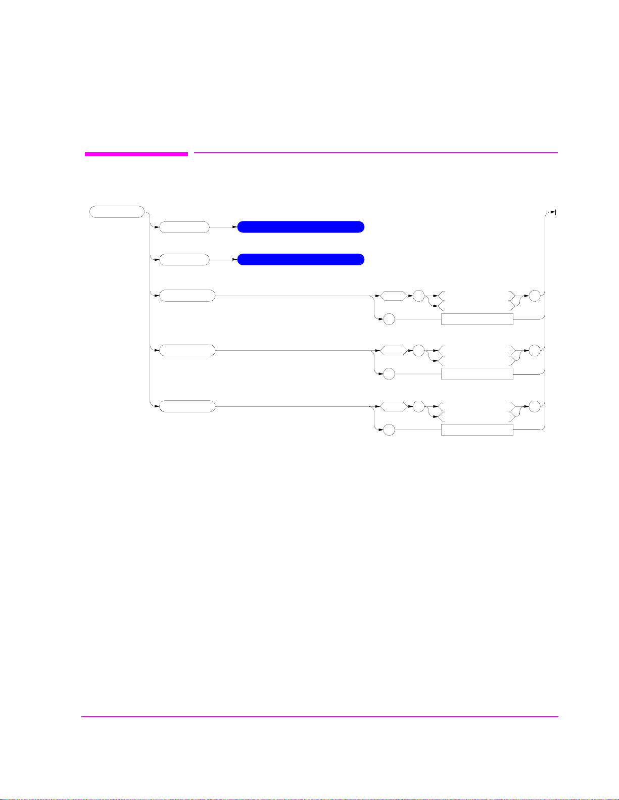
Adjacent Channel Power (ACP)
:ACPower
:CBAN
(Channel BW)
See Real Number Setting Syntax*
*Does not include the :STATe command
Adjacent Channel Power (ACP)
:COFFset
(Ch Offset)
:MEASurement
(ACP Meas)
:RBANdwidth
(Res BW)
:RMODulation
(Carrier Ref)
See Real Number Setting Syntax*
*Does not include the :STATe command
space
?
space
?
space
?
’
Returns quoted string
’
Returns quoted string
’
Returns quoted string
Ratio
Level
300 Hz
1 kHz
Unmod
Mod
’
’
’
95
Page 96

Adjacent Channel Power (ACP)
96
S:\agilent\8920\8920b\PRGGUIDE\BOOK\SECTIONS\acp.sec
Page 97

AF Analyzer
:AFANalyzer
:AIN
(Audio In Lo)
:CURRent
:ZERO
space
?
’
Returns quoted string
Gnd
Float
600 To Hi
AF Analyzer
’
:DEMPhasis
:DETector
:GAIN
(De-Emp Gain)
:PKLocation
(Pk Det To)
:SETTling
space
?
space
?
space
?
space
?
space
’
Returns quoted string
’
Returns quoted string
’
Returns quoted string
’
Returns quoted string
’
750 uS
Off
0 dB
10 dB
20 dB
30 dB
RMS
RMS*SQRT2
PK+
PK-
PK+-/2
PK+MAX
PK+HOLD
PK-HOLD
PK+-/2 Hd
PK+-MX Hd
Filters
De-Emp
Fast
Slow
’
’
’
’
’
:AFAN continued
?
Returns quoted string
97
Page 98

AF Analyzer
:AFANalyzer
:ELResistor
:FILTer1
See Real Number Setting Syntax*
*Does not include the :ST ATe command
space
?
’
Optional Filters
Returns quoted string
<20Hz HPF
50Hz HPF
300Hz HPF
’
:FILTer2
:GTIMe
:INPut
(AF Anl In)
:AFAN continued
See Real Number Setting Syntax*
*Does not include the :ST ATe command
:GAIN
(Input Gain)
space
?
space
?
space
?
’
Optional Filters
Returns quoted string
’
Returns quoted string
’
Returns quoted string
300Hz LPF
3kHz LPF
15kHz LPF
>99kHz LP
FM Demod
AM Demod
SSB Demod
Audio In
Radio Int
Ext Mod
Mic Mod
FM Mod
AM Mod
Audio Out
0 dB
20 dB
40 dB
’
’
’
98
S:\agilent\8920\8920b\PRGGUIDE\BOOK\SECTIONS\afan.sec
Page 99

:AFA Nalyzer
:NOTCh
:FREQuency
:GAIN
See Real Number Setting Syntax*
*Does not include the :STATe command
space
’
?
0 dB
10 dB
20 dB
30 dB
40 dB
Returns quoted string
AF Analyzer
’
:RANGing
:SMPoint
(Scope To)
:SPEaker
:MODE
(Speaker ALC)
:VOLume
space
?
space
?
space
?
space
?
’
Returns quoted string
’
Returns quoted string
’
Returns quoted string
’
Returns quoted string
Auto
Hold
De-Emp
Filters
Input
Notch
On
Off
Pot
Off
’
’
’
’
99
Page 100

AF Generator 1
AF Generator 1
:AFGenerator1
:AFG1
:DESTination
(AFGen1 To)
:AM
1
See Real Number Setting Syntax
space
?
’
Returns quoted string
AM
FM
Audio Out
’
:FM
:OUTPut
:FREQuency
1
In setting AFGener ator 1, you must fi rs t select a destination (DESTination), then
2
2
See Real Number Setting Syntax
See Real Number Setting Syntax
See Real Number Setting Syntax*
*Does not include the :ST ATe command
set the modulation depth (AM), or deviation (FM) or amplitude (OUTPut), then
set the modulation rate or audio output frequency (FREQuency)
2
AM sets depth when DESTination set to AM.
FM sets deviation when DESTination set to FM.
OUTPut sets amplitude when DESTination set to Audio Out.
FREQuency sets modulation rate when DESTination set to AM, FM.
FREQuency sets audio output frequency when DESTination set to Audio Out.
100
S:\agilent\8920\8920b\PRGGUIDE\BOOK\SECTIONS\afg1.sec
 Loading...