

Page 1

Model 979 Helium
NOTICE: This document contains references to Varian.
Please note that Varian, Inc. is now part of Agilent
Technologies. For more information, go to
www.agilent.com/chem.
vacuum technologies
3
FIELD SERVICE
COMPONENT REPLACEMENT
Mass Spectrometer
Leak Detector
MANUAL
DRAFT 1/27/0
Manual No. 699909976
Revision B
January 2003
Page 2
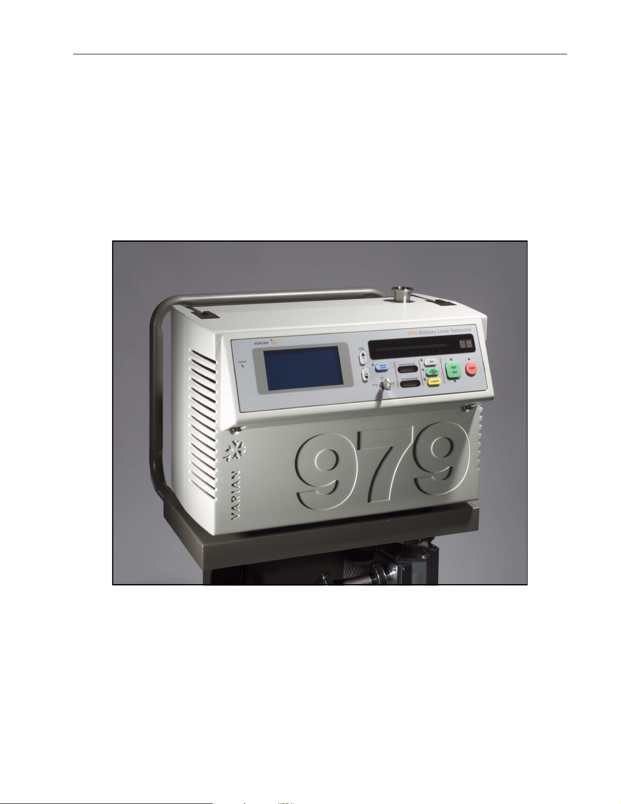
Model 979 Helium Mass Spectrometer Leak Detector
Model 979 Helium Mass Spectrometer
Leak Detector
DRAFT 1/27/03
Alconox is a registered trademark of Alconox, Inc.
Apiezon is a registered trademark of M&I Materials Ltd.
Scotch-Brite is a trademark of 3M.
Loctite and PST are registered trademarks of Loctite Corporation
Teflon is a registered trademarks of E. I. du Pont de Nemours and Company.
Copyright 2003
Varian Vacuum Technologies
Page 3

D
eclaration o
fC
ity
Declaration of Conformity
Konformitätserklärung
Déclaration de Conformité
Declaración de Conformidad
Verklaring de Overeenstemming
Dichiarazione di Conformità
We/Wir/Nous/Nosotros/Wij/Noi: Varian, Inc.
Varian Vacu um Technologies
121 Hartwell Avenue
Lexington, MA, 02421-3133 USA
declare under our sole responsibility that the product,
erklären, in alleniniger Verantwortung, daß dieses Produkt,
déclarons sous notre seule responsabilité que le produit,
declaramos, bajo nuestra sola responsabilidad, que el producto,
verklaren onder onze verantwoordelijkheid, dat het product,
dichiariamo sotto nostra unica responsabilità, che il prodotto,
Model 979 Helium Mass Spectrometer Leak Detector
onform
to which this declaration relates is in conformity with the following standard(s) or other normative documents.
auf das sich diese Erklärung bezieht, mit der/den flogenden Norm(en) oder Richtlinie(n) übereinstimmt.
auquel se réfère cette déclaration est conforme à la (auz) norme(s) ou au(x) document(s) normatif(s).
al que se refiere esta declaración es conforme a la(s) norma(s) u otro(s) documento(s) normativo(s).
waamaar deze verklaring verwijst, aan de volende norm(en) of richtlijn(en) beantwoodt.
a cui se rifersce questa dichiarazione è conforme alla/e sequente/I norma/o documento/I normativo/i.
89/336/EEC. . . . . . . . . . . . . . . . . . . . . . Electromagnetic Compatibility Directive
EN61326:1997. . . . . . . . . . . . . . . . . . . Measurement Control and Laboratory Equipment EMC Requirements
Frederick C. Campbell
Operations Manager
Varian Vacuum Technologies
Lexington, Massachusetts, USA
June 2002
Page 4

Model 979 Helium Mass Spectrometer Leak Detector
Warranty
Products manufactured by Seller are warrant ed against defects in materials and workmanship for
twelve (12) months from date of shipment thereof to Customer, and Seller’s liability under valid warranty claims is limited, at the option of Seller, to repair, to replace, or refund of an equitable portion of
the purchase price of the Product. I tems expe ndable in normal us e are not cover ed by this warr anty. All
warranty replacement or repair of parts shall be limited to equipment malfunctions which, in the sole
opinion of Seller, are due or traceable to defects in original materials or workmanship. All obligations
of Seller under this warranty shall cease in th e event of abuse, acc ident, altera tion, misuse , or neglect of
the equipment. In-warranty repaired or replaced parts are warranted only for the remaining unexpired
portion of the original warranty period applicable to the repaired or replaced parts. After expiration of
the applicable warranty peri od, Customer shall be charged at the then current prices for part s, labor,
and transportation.
Reasonable care must be used to avoid hazards. Seller expressly disclaims responsibility for loss or
damage caused by use of its Products other than in accordance with proper operating procedures.
Except as stated herein, Seller makes no warranty, express or implied (either in fact or by operation of
law), statut o r y o r otherwise; an d , e xc e p t as stated here in , Seller shall have no liab ili ty under any warranty, express or implied (eith er in f act or by oper ation of l aw), st atuto ry or other wis e. Sta tements made
by any person, including repr esentatives of Seller, which are inconsistent or i n conflict with th e terms of
this warranty shall not be binding upon Sel ler unless reduced to writing and approved by an officer of
Seller.
Warranty Replacement and Adjustment
All claims under warranty must be made promptly afte r occurrence of cir cumstances giving rise the reto,
and must be received within the applica ble warranty period by Seller or its authorized representative.
Such claims should include the Product serial number, the date of shipment, and a full description of
the circumstances giving rise to the claim. Before any Products are returned for repair and/or adjustment, written author ization f rom Sell er or it s auth orized repr esenta tive fo r the re turn and instru ctions as
DRAFT 1/27/03
to how and where these Products should be returned must be obtained. Any Product returned to Seller
for examination shall be prepaid via the means of transportation indicated as acceptable by Seller.
Seller reserves the right to reject any warranty claim not promptly reported and any warranty claim on
any item that has been altered or has been returned by non-acceptable means of transportation. When
any Product is returned for examination and inspection, or for any other reason, Customer shall be
responsible for all damage resulting from improper packing or handling, and for loss in transit, not withstanding any defect or non-conformity in the Product. In all cases, Seller has the sole responsibili ty for
determining the cause and nature of failure, and Seller’s determina tio n w ith regard the reto shall be
final.
If it is found that Seller’s Product has been returned without caus e and i s still s ervice able, Customer will
be notified and the Product returned at Customer expense; in addition, a charge for testing and examination may be made on Products so returned.
ii
Page 5
Model 979 Helium Mass Spectrometer Leak Detector
l
Items Not Covered Under Warranty
Examples of items not normally covered under warranty include ion sources, TC gauges, O-rings,
spectrometer tube cleaning and overhaul, mechanical pump oils, vacuum system overhauls, and
obvious abuse or customer error. These items are considered normal maintenance for this type of
equipment.
3/1/00
Hazard and Safety Information
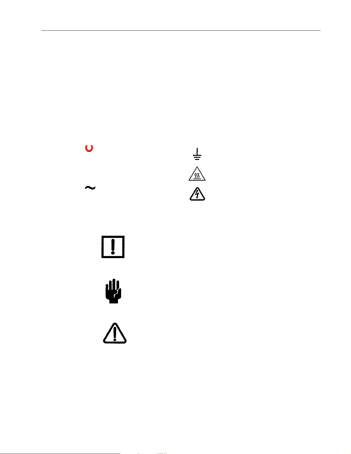
Some common international symbols used in this manual and the equipment itself are
shown below.
OFF Power Switch Position Earth Ground
ON Power Switch Position Hot Surface
AC – Alternating Current Dangerous Voltage, Risk of
Electrical Shock
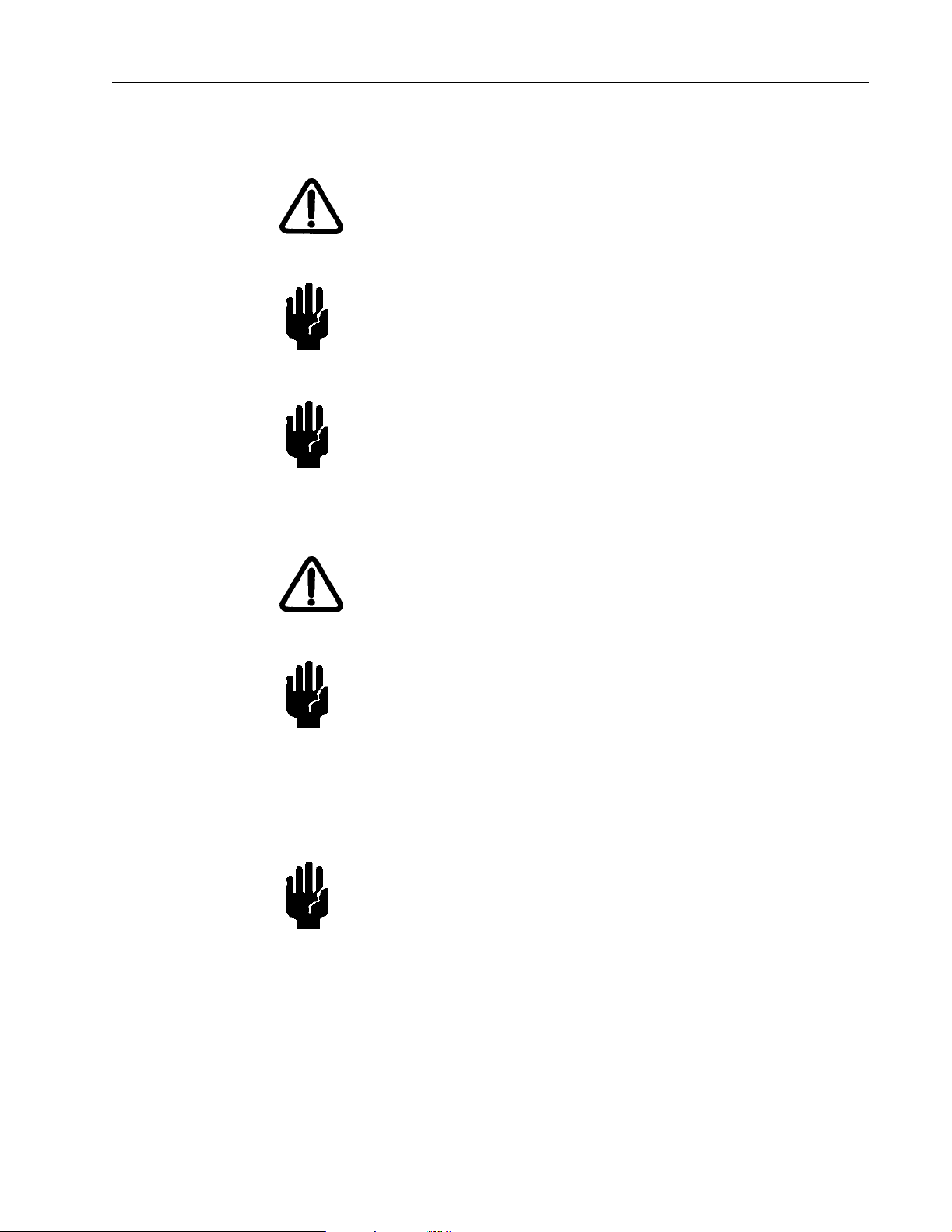
This manual uses the following standard safety protocols:
NOTE The notes contain important information taken from the text.
CAUTION The caution messages are displayed before procedures, which
if not followed, could cause damage to the equipment.
WARNING The warning messages are for attracting the attention of the
operator to a particular procedure or practice which, if not
followed correctly, could lead to serious injury.
DRAFT 1/27/03
iii
Page 6

Solvents
Model 979 Helium Mass Spectrometer Leak Detector
Operators and service personnel must be aware of all hazards associated with this
equipment. They must know how to recognize hazardous and potentially hazardous
conditions, and know how to avoid them. The consequences of unskilled, improper, or
careless operation of the equipment can be serious. This product must only be operat ed and
maintained by trained personnel. Every operator or service person must read and
thoroughly understand operation/maintenance manuals and any additional information
provided by Varian Vacuum Technologies. All warning and cautions should be read
carefully and strictly ob served. Consult lo cal, state, and national agencies r egarding specif ic
requirements and regulati ons. Address any safety, operation, and/or maintenance questions
to your nearest Varian Vacuum Technologies office.
CAUTION The mechanical components of leak detectors are typically
cleaned with alcohol, methanol, or other solvents. When
heated, sprayed, or exposed to high-temperature equipment,
these solvents become flammable and explosive, causing
serious injury or death. Do not use th ese solvents near a
high-temperature source. Ventilate the working area with a
blower and work in a large, well-ventilated room.
DRAFT 1/27/03
Alcohol, methanol, or other solvents are irritants, narcotics,
depressants and/or carcinogens. Their inhalation and/or
ingestion may produce serious side effects. Prolonged or
continued contact with the skin will result in absorption
through the skin and moderate toxicity. Always ensure that
cleaning operations are carried out in large, well-ventilated
rooms, and wear eyeshields, gloves, and protective clothing.
CAUTION Do not clean any aluminum parts with Alconox
not compatible with aluminum and will cause damage.
NOTE During reassembly, always use Loctite
(teflon-impregnated pipe thread compound) on pipe threads.
PST
®
. Alconox is
iv
Page 7
Model 979 Helium Mass Spectrometer Leak Detector
Equipment, General
WARNING Equipmen t ti gh tness is guaranteed for n o rm a l operating
CAUTION The performance and operating safety of this equipment can
CAUTION Always allow at least 4 inches of clearance adjacent to the
Power and Static
conditions when the equipment le aves the factory. It is the
user’s responsibility to maintain the level of tightness
particularly when pumping dangerous products.
only be guaranteed if it is operated acc ording to normal
conditi o ns of use.
ventilation holes at the front, back and bottom of the equipment
enclosure.
WARNING Disconnect power from the 979 before performing any
maintenance procedure that requires physically disconnecting
any part of the system.
CAUTION Varian strongly recommends the use of surge protect ion to
improve the immunity of the 979 Series leak detectors against
unidirectional transients caused by the following phenomena:
❑ Switching phenomena in the power network ( e.g., switchi ng
of capacitor banks)
❑ Faults in the power network
❑ Indirect lightning strokes
CAUTION Many components of the 979 are static sensitive devices.
Varian Vacuum Technologies recommends that you wear a
grounding device when performing any maintenance on the
979 and especially when performing maintenance of static
sensitive parts.
DRAFT 1/27/03
v
Page 8

Model 979 Helium Mass Spectrometer Leak Detector
WARNING This equipment is designed to meet current EEC regulations:
LVD (Low Voltage Directive, 73/23/EEC) and EMC
(Electromagnetic Compatibility, 89/336/EEC Directive) for
Installation Category II , Pollution Degree II environment for
Industrial, Scientific, Measuring and Process Control electrical
equipment.
❑ Any modifications on the part of the user are liable to cause
non-compliance with regulations or affect the EMC
performance and the safety of the product. Varian Vacuum
Technologies cannot be held responsibl e for consequences
resulting from such intervention.
❑ The equipment can be damaged by incorrect mains AC
supply voltages, the Radio Frequency (RF) and Electrostatic
Discharge (ESD) energy inputs that can exceed the
maximum ratings, operating in very hig h temperatures or
without adequate ventilation, immersion in liquids, and
physical abuse.
❑ All electrical connections must be perf ormed by a qualified
electrician and must comply with national and local codes.
DRAFT 1/27/03
❑ Ensure that the electrical installation conforms with your
local safety requirements.
❑ Electrical installati on must include the appropriate branch
circuit (at least 2 0 A) w i th a lo n g ti me de lay and a relia b le
earth ground. Do not use an extension cord.
❑ Use only the power cord that was provided with your leak
detector. The use of extension cords is not recommended
and could result in damage to the equipment and los s of
warranty.
❑ To avoid electric shock, connect the product power cord to
a grounded power receptacle. A protective ground
connection by way of the grounding condu ctor in the power
cord is essential for safe operation.
❑ Before powering the unit the first time, verify that the unit is
configured to operate for the local mains supply voltage.
❑ Opening the enclosure may expose hazardous voltages.
Always disconnect the power cord and inter face cables
before opening the enclosure. Do not touch the power
inlet’s contacts for at least 10 seconds after disconnecting
the power cord.
vi
Page 9

Model 979 Helium Mass Spectrometer Leak Detector
CAUTION This equipment generates , uses, and can radiate RF energy and
if not installed and used in accordance with the instructional
manual, may cause harmful interference to radio
communications.
When this equipment is operated in a commerci al environment
operation is subject to the foll owin g two conditions:
❑ This equipment may not cause harmful interference, and
❑ This equipment must accept any interference received,
including interference (RF and ESD) that may cause
undesired operation.
This equipment may need to be res et after RF and/or ES D events
by cycling the Power Switch/Circuit Breaker on the back panel
of the unit.
Operation of this equipment i n a residential ar ea is also likely t o
cause harmful radio communications interference in which
case the user will be required to correct the interference at his
own expense.
Vacuum Equipment and Cleanliness
Cleanliness is vital when servicing the leak detector or any vacuum equipment. There are
some techniques that are more important in leak detector servicing than in general vacuum
work:
CAUTION Do not use sili c o ne oil or silicon e grease.
Use powder-free butyl or polycarbonate gloves to prevent skin
oils from getting on vacuum surfaces.
Do not clean any aluminum parts with Alconox
not compatible with aluminum and will cause damage.
NOTE Normally, it is unnecessary to use vacuum grease. However, if
it must be used, avoid silicone types, and use it sparingly .
Apiezon
Technologies Part No. 695400004).
®
L grease is recommended (Varian Vacuum
®
. Alconox is
DRAFT 1/27/03
vii
Page 10

O-ring Care
When removing, checking or replacing O-rings:
Model 979 Helium Mass Spectrometer Leak Detector
NOTE Varian Vacuum Technologies recommends replacing all
O-rings during routine maintenan ce or during any maintenance
procedure requiring that O-rin gs be removed.
CAUTION Remove O-rings carefully with your fin gers. Do not use metal
tools for this task. This prevents scratching of any sealing
surfaces.
❑ Wipe all O-rings clean with a lint-free cloth before
installatio n to en s u re th at no foreign ma t te r is present to
impair the se al .
❑ Do not use grease or other substance on O-rings that will
come in contact with the spectrometer tube.
❑ Do not use alcohol, methanol or other solvents on O-rings.
To do so causes deterioration and reduces their ability to
hold a vacuum.
❑ If applicable, apply a small amount of Apiezon
and wipe the O-rings “shiny” dry.
®
L grease
DRAFT 1/27/03
NOTE Due to the effective cleaning nature of VacuSolv solvent and
its residue-free properties, Varian Vacuum T echnologies’
Component and Spectrometer Tube Cleaning Kit
(Part Number 670029096), used in accordance with the kit
instructions, is recommended for cleaning the spectrometer
tube components. The kit can also be used for fine cleaning
other parts in the leak de tector’s vacuum system such as valves
and fittings. No rinsing steps or high-t emperature d ry in g is
required following cleaning wit h VacuSolv. Although
appropriate precaution s are advised, VacuSolv is co mpa tible
with most materials and does not contain toxic chemicals or
CFCs (chlorofluorocarbons).
viii
Page 11
Model 979 Helium Mass Spectrometer Leak Detector
Spectrometer Tube
CAUTION The spectrometer tube operates at a very high vacuum
produced by the high vacuum pump. Service of the
spectrometer tube requires that this vacuum be vented to the
atmosphere.
CAUTION Do not use grease or ot her subs ta nce on O-ri ngs that will c ome
in contact with the spectrometer tube.
CAUTION If the spectro m e te r tu b e magnet com e s in co n ta c t w i th a
magnetic surface, the magnet may lose its gauss, causing the
spectrometer tube to lose sensitivity.
WARNING Store the Ion Source in a cool, dry area in a ti ghtly sealed
container. Wash hands thoroughly after handling the Ion
Source and especially befo re smoking or eating.
Gross Leak Option
If the Gross Le ak o pt ion is installe d :
CAUTION The Gross Leak is calibrated at the fact ory and if any alteration
is made, the Gross Leak must be returned to the factory for
recalibration. F or ret urns , cont act Varian Vacuum Technologies
Customer Service at 1-800-8VARIAN.
DRAFT 1/27/03
ix
Page 12
Pumps
Model 979 Helium Mass Spectrometer Leak Detector
WARNING To avoid injury, use proper lifting techniques when moving
pumps. Your system may have pumps that require two people
to move them safely.
WARNING The vacuum pumps are also compressors; incorrect operation
may be dangerous. Study the “Mechanical Pump Operation
Manual” enclosed with your pump before starting the pumps.
The pumps are designed to prevent any thermal risk for user
safety. However, specific operating conditions may generate
temperatures >70 °C.
Hot oil will burn the skin. Service of the pumps in this area
must be performed by authorized personnel onl y. Stand back
from mechanical pump before starting.
CAUTION Check the oil level often. Do not allow oil-based mechanical
pumps to run when oil level is below LOW mark. Damage to
pumps can occur if operated with no oil.
DRAFT 1/27/03
WARNING To avoid injury, wait until the turbo pump is completely
stopped before disconnecting it from the vacuum system.
x
Page 13

Model 979 Helium Mass Spectrometer Leak Detector
Varian Services
The following are just a f ew of the many se rvi ces that Varian offers i ts cust omers . Pleas e see
our catalog, or contact us to learn of the se rvi ces tha t a re avai labl e. Conta ct Varian Vacuum
Technologies Customer Service at 1-8 00-8VARIAN for details.
❑ Rebuilt spectrometer tubes are available on an exchange basis.
❑ NIST-traceable calibrated leak testi ng and verification services.
Contacting Varian Vacuum Technologies
In the United States, you can contact Varian Vacuum Technologies Customer Service at
1-800-8VARIAN.
Internet users:
❑ Send email to Customer Service & Technical Support at
vpl.customer.support@varianinc.com
❑ Visit our web site at www.varianinc. com/vacuum
❑ Order on line at www.evarian.com
See the back cover of this manual for a listing of our sales and service offices.
Tools Required for Component Replacement
The following tools are required for component replacement
❑ Phillips screwdriver ❑ 9-16Wrench
❑ Slotted screwdriver ❑ 13-16 Wrench
❑ Long slotted screwdriver ❑ 11-32 Nut driver
❑ Crescent wrench ❑ 5-64 Allenwrench
❑ PLCC chip extracting device,
such as an AMP 821903-5
❑ A non-metal device for removing O-rings
Materials (not Parts) Required for Component Replacement
❑
Powder-free butyl or
polycarbonate gloves
❑ VacuSolv or similar solvent
DRAFT 1/27/03
❑ Clean, non-magnet ic surface ❑ Cotton swabs
❑ Lint-free wipes ❑ Loctite PST 565 Thread Sealant
xi
Page 14

Preface
This manual contains information for field replacement of components of the Model 979
Mass Spectrometer Heli um Leak Detect or. It is organ ized so that simila r items or procedures
are included in a section. The manual moves from a brief overview of the leak detector to
specific replac ement procedur es to c ali brati on and tuning pr ocedu res t hat mus t be run a ft er
the replacement of certain componen ts. Photographs are liberally used to help document
procedures. An appendix provides Assembly Drawings and Bills of Materials for reference.
The specific sections included in the manual are:
Model 979 Helium Mass Spectrometer Leak Detector
Preface
Section 1 “System Overview”
Section 2 “Cleaning the Test Port”
Section 3 “Removing the Covers
from the 979”
Section 4 “The Internal Calibrated Leak”
Section 5 “Spectrometer Tube Assembly”
Section 6 “Test Port Thermocouple Gauge”
DRAFT 1/27/03
Section 7 “TheVarianPlatform”
Section 8 “Internal High Speed Turbo and
Mechanical Pumps”
Contains information relevant to the remainder
of the manual.
A brief overview of the 979.
How to clean the test port.
How to open individual sections or all of the
979 covers.
Detailed steps for removing and replacing the
calibrated leak.
Spectrometer tube assembly procedures from
replacement as an assembly to replacement of
individual components. This section also
includes a full overhaul procedure.
How to access and replace the test port
thermocouple gauge.
Procedures to access and replace the printed
circuit boards that make up the Varian Platform.
Replacement of the turbo pump and the
mechanical pumps.
xii
Section 9 “Calibration and Manual Tuning”
Section 10 “Leak Checking for Reliability”
Section A “Assembly Drawings and
Bills of Materials”
Section B “979 COM Cable” 979 COM Cable sketch and pinout assignments .
Section C “979 Spare Parts List” A table of the 979 Spare Parts List with ordering
Procedures that must be completed after
replacement of certain components.
General information regarding testing for leaks
after component replacement.
Assembly drawings and Bills of Materials for
reference.
numbers.
Page 15

Model 979 Helium Mass Spectrometer Leak Detector
DRAFT 1/27/03
xiii
Page 16

Model 979 Helium Mass Spectrometer Leak Detector
DRAFT 1/27/03
This page intentionally left blank.
Page 17

Model 979 Helium Mass Spectrometer Leak Detector
Table of Contents
Warranty .............................................................................................................................................ii
Preface ..............................................................................................................................................xii
Section 1. System Overview ...........................................................................................................1-1
1.1 Front Panel Displays and Controls ......................................................................................1-1
1.1.1 Key Switch ..................................................................................................................1-2
1.2 Rear Panel...........................................................................................................................1-3
1.2.2 System Control and Communication Panel ................................................................1-3
1.3 Inside the Model 979............................................................................................................1-4
1.3.1 Inside Front View ........................................................................................................1-4
1.3.2 Side View — Card Cage Side.....................................................................................1-5
1.3.3 Side View — Calibrated Leak, Valve Block Side ........................................................1-6
1.3.4 Rear View....................................................................................................................1-6
Section 2. Cleaning the Test Port ...................................................................................................2-1
Section 3. Removing the Covers from the 979 ...............................................................................3-1
3.1 Opening the Front Panel .....................................................................................................3-1
3.2 R emoving the Front Panel...................................................................................................3-3
3.3 Removing the Rear Panel....................................................................................................3-5
3.4 R emoving the Side Panel ....................................................................................................3-6
3.5 R eplacing All Covers and Panels.........................................................................................3-7
3.5.1 Replacing the Side Panel............................................................................................3-7
3.5.2 Replacing the Rear Panel...........................................................................................3-7
3.5.3 Replacing the Front Panel...........................................................................................3-7
Section 4. The Internal Calibrated Leak ..........................................................................................4-1
4.1 Recalibrating the Internal Calibrated Leak ..........................................................................4-1
4.2 Replacing the Internal Calibrated Leak................................................................................4-1
4.2.1 Removing the Valve Block Coil and Plunger Assembly..............................................4-2
4.2.2 Removing the Internal Calibrate Leak.........................................................................4-6
4.2.3 Replacing the Internal Calibrated Leak.......................................................................4-9
4.2.4 Examining and Cleaning the Valve Block Coil and Plunger Assembly.....................4-11
4.2.4.1 Examining and Cleaning the Cal Leak Valve Block .....................................4-11
4.2.4.2 Examining and Cleaning the Coil and Plunger Assembly ............................4-12
4.2.4.3 Examining and Cleaning the Valve Stem and End Cap ...............................4-13
4.2.5 Replacing the Coil and Plunger Assembly................................................................4-14
DRAFT 1/27/03
Section 5. Spectrometer Tube Assembly ........................................................................................5-1
5.1 Spectrometer Tube Exchange ............................................................................................5-1
5.1.1 Removing the Spectrometer Tube Assembly for Complete Exchange.......................5-1
5.1.2 Examining and Cleaning the Centering Ring and O-Ring...........................................5-5
5.2 Reinstalling the Spectrometer Tube.....................................................................................5-6
5.3 R emoving the Button Thermocouple from the Spectrometer Tube .....................................5-7
xv
Page 18

Model 979 Helium Mass Spectrometer Leak Detector
5.4 Replacing the Button Thermocouple..................................................................................5-10
5.5 Removing the Ion Source ..................................................................................................5-12
5.6 Replacing the Ion Source...................................................................................................5-15
5.7 Removing the Preamplifier.................................................................................................5-17
5.8 Replacing the Preamplifier.................................................................................................5-19
5.9 S pectrometer Tube Overhaul .............................................................................................5-20
5.9.1 Removing the Spectrometer Tube Assembly as Part of Overhaul............................5-21
5.9.2 Removing the Magnet Assembly from Spectrometer Tube as Part of Overhaul ......5-25
5.9.3 Removing the Button Thermocouple as part of Spectrometer Tube Overhaul.........5-26
5.9.4 Removing the Ion Source as part of Spectrometer Tube Overhaul..........................5-27
5.9.5 Removing the Preamplifier as Part of Spectrometer Tube Overhaul........................5-30
5.9.6 Removing the Deflecting Magnetic Pole Pieces as Part of
Spectrometer Tube Overhaul.............................................................................................5-31
5.9.7 Examining and Cleaning the Spectrometer Parts.....................................................5-32
5.10 Reassembling the Spectrometer Tube ............................................................................5-35
5.10.1 Replacing the Deflecting Magnetic Pole Pieces......................................................5-35
5.10.2 Replacing the Preamplifier as Part of Spectrometer Tube Overhaul......................5-35
5.10.3 Replacing the Ion Source as Part of Spectrometer Tube Overhaul........................5-36
5.10.4 Replacing the Button Thermocouple as Part of Spectrometer Tube Overhaul.......5-39
5.10.5 Replacing the Magnet Assembly.............................................................................5-40
5.10.6 Re-Installing the Spectrometer Tube ......................................................................5-43
Section 6. Test Port Thermocouple Gauge .....................................................................................6-1
6.1 R emoving the Test Port Thermocouple Gauge ..................................................................6-1
6.2 Replacing the Test Port Thermocouple Gauge....................................................................6-3
Section 7. The Varian Platform .......................................................................................................7-1
7.1 Location of Circuit Boards ...................................................................................................7-1
7.2 Removing the Card Stack from the Card Cage ................................................................... 7-3
7.2.1 Removing the Connections from the Front of the Boards...........................................7-4
7.2.2 Removing the Connections from the Back of the Boards ...........................................7-5
7.2.3 Removing the CPU Board Power Connection ............................................................7-6
7.2.4 Removing the Card Stack...........................................................................................7-7
7.3 Replacing a Board ...............................................................................................................7-8
7.4 Replacing the Card Stack into the Card Cage.....................................................................7-9
7.5 Replacing the Turbo Controller Board ...............................................................................7-10
7.5.1 Removing the Turbo Controller Board ......................................................................7-11
7.5.2 Installing the Turbo Controller Board ........................................................................7-12
7.6 The Touch Screen and Control Panel Assemblies ............................................................7-12
7.6.1 Removing the Touch Screen Assembly....................................................................7-13
7.6.2 Replacing the Touch Screen Assembly....................................................................7-15
7.6.3 Removing the Control Panel Assembly.....................................................................7-16
7.6.4 Replacing the Control Panel Assembly.....................................................................7-17
DRAFT 1/27/03
xvi
Page 19

Model 979 Helium Mass Spectrometer Leak Detector
Section 8. ...................................................... Internal High Speed Turbo and Mechanical Pumps 8-1
8.1 Removing the Turbo Pump .................................................................................................8-1
8.1.1 Moving the Spectrometer Tube Assembly ..................................................................8-2
8.1.2 Removing the Turbo-to-Spec Tube Manifold ..............................................................8-4
8.1.3 Removing the Power and Valve Block Connections...................................................8-5
8.2 Replacing the Turbo Pump ..................................................................................................8-6
8.2.1 Examining and Cleaning Centering Rings, O-rings and the Manifold.........................8-6
8.2.2 Replacing the Turbo Pump .........................................................................................8-7
8.2.3 Replace the Turbo-to-Spec Tube Manifold.................................................................8-8
8.2.4 Replacing the Spectrometer Tube ..............................................................................8-9
8.3 Replacing the Mechanical Pumps......................................................................................8-10
8.3.1 Examining and Cleaning the Centering Ring and O-Ring.........................................8-13
8.3.2 Replacing the Mechanical Pumps.............................................................................8-14
8.4 Changing the Mechanical Pump Fluid ...............................................................................8-14
8.5 Replacing Tip Seals in Dry Mechanical Pumps .................................................................8-14
Section 9. Calibration and Manual Tuning ......................................................................................9-1
9.1 Calibrate the 979 .................................................................................................................9-1
9.2 M anual Tuning.....................................................................................................................9-2
9.2.1 Manual Tuning using the Front Panel Touch Screen..................................................9-2
9.2.2 Manual Tuning using the Serial Port...........................................................................9-4
9.3 Gauge Calibration Procedures.............................................................................................9-6
9.3.1 System Pressure Gauge Calibration Procedure.........................................................9-7
9.3.1.1 Vacuum (Low Pressure) Calibration ...............................................................9-7
9.3.1.2 Atmospheric Calibration ................................................................................. 9-8
9.3.2 Test Port Pressure Thermocouple Gauge C alibration Procedure...............................9-8
9.3.2.1 Vacuum (Low Pressure) Calibration ...............................................................9-9
9.3.2.2 Atmospheric Calibration ................................................................................. 9-9
Section 10. Leak Checking for Reliability ....................................................................................... 10-i
10.1 General Suggestions for Leak Checking .........................................................................10-i
Appendix A. Assembly Drawings and Bills of Materials ..................................................................A-1
Appendix B. 979 COM Cable ..........................................................................................................B-1
Appendix C. 979 Spare Parts List .................................................................................................. C-1
Index .................................................................................................................................................. 1
xvii
DRAFT 1/27/03
Page 20

Model 979 Helium Mass Spectrometer Leak Detector
DRAFT 1/27/03
This page intentionally left blank.
Page 21

Model 979 Helium Mass Spectrometer Leak Detector
List of Figures
Figure Description Page
1-1 979 Front Panel Displays and Controls ..............................................................................1-1
1-2 979 Rear Panel...................................................................................................................1-3
1-3 979 System Control and Communication Panel .................................................................1-3
1-4 979 Interior: Front View.......................................................................................................1-4
1-5 979 Interior: Side View Card Cage .....................................................................................1-5
1-6 979 Interior: Side View Valve Block and Internal Calibrated Leak......................................1-6
2-1 Test Port with Blank-Off Flange Cap ..................................................................................2-1
2-2 Centering Ring with O-ring..................................................................................................2-2
2-3 O-ring and Centering Ring on Test Port .............................................................................2-3
2-4 Test Port with Connected Device........................................................................................2-3
3-1 979 Front Panel ..................................................................................................................3-1
3-2 Molex Connector on Touch Panel Assembly......................................................................3-2
3-3 Front Panel Ground Strap...................................................................................................3-3
3-4 Ground Strap Removal from Front Panel ...........................................................................3-3
3-5 Rear Panel Removal...........................................................................................................3-5
3-6 Side Panel Removal ...........................................................................................................3-6
3-7 Front Panel PCB Harness Connector. ................................................................................3-8
4-1 979 Side View: Removal of Valve Block Coil and Plunger Assembly.................................4-1
4-2 979 Side View.....................................................................................................................4-2
4-3 End Cap and Valve Stem....................................................................................................4-3
4-4 Valve Stem with End Cap Removed...................................................................................4-3
4-5 Valve Stem Removal ..........................................................................................................4-4
4-6 V7 Valve Block Power Connector Removal........................................................................4-4
4-7 Slotted Post on Coil and Plunger Assembly .......................................................................4-5
4-8 Securing the Coil to Loosen Plunger Assembly..................................................................4-5
4-9 979 Side View: End Cap, Valve Stem, and Coil and Plunger Assembly Removed............4-6
4-10 Elbow Flat Secured with Crescent Wrench.........................................................................4-7
4-11 Loosening Leak with Open W rench....................................................................................4-7
4-12 Removal of Calibrated Leak................................................................................................4-8
4-13 Elbow after Removal of Calibrated Leak.............................................................................4-9
4-14 Connecting Leak with Open Wrench ................................................................................4-10
4-15 Calibrated Leak Strap Replacement.................................................................................4-10
4-16 Top of Plunger..................................................................................................................4-12
4-17 Bottom of Plunger.............................................................................................................4-13
4-18 Placement of Plunger Assembly into Coil.........................................................................4-14
4-19 Coil and Plunger Assembly Replacement.........................................................................4-15
4-20 Positioning Valve Stem onto Coil and Plunger Assembly.................................................4-15
4-21 End Cap Replacement......................................................................................................4-16
5-1 Spectrometer Tube and Turbo Pump .................................................................................5-2
5-2 Ground Cable and Screw for Removing Connectors..........................................................5-3
DRAFT 1/27/03
xix
Page 22

Model 979 Helium Mass Spectrometer Leak Detector
5-3 Wing Nut Under Shelf.........................................................................................................5-3
5-4 NW-25 Quick Clamp on Turbo-to-Spec Tube Manifold......................................................5-4
5-5 O-ring Inspection ................................................................................................................5-5
5-6 Button TC, Spectrometer Tube, and Turbo Pump..............................................................5-7
5-7 Connector Removal............................................................................................................5-8
5-8 Phillips Screws on Button TC Assembly.............................................................................5-8
5-9 Flange Cap and Center Post on Button TC Assembly .......................................................5-9
5-10 Sensing Wire ....................................................................................................................5-10
5-11 Flange Cap Grooves.........................................................................................................5-11
5-12 Ion Source, Spectrometer Tube, and Turbo Pump...........................................................5-12
5-13 Ion Source Removal ......................................................................................................... 5-13
5-14 Alignment Pin.................................................................................................................... 5-14
5-15 Alignment Hold and Ground Slit Plate in Ion Source Cavity.............................................5-14
5-16 Ion Source Insertion..........................................................................................................5-15
5-17 Alignment of Flange Cap Grooves with Ion Source Center Legs .....................................5-16
5-18 Spectrometer Tube and Turbo Pump ...............................................................................5-17
5-19 Preamplifier Removal ....................................................................................................... 5-18
5-20 Preamplifier Slot and Alignment Pin ................................................................................. 5-19
5-21 Alignment of Flange Cap Grooves with Preamplifier Legs...............................................5-19
5-22 Spectrometer Tube and Turbo Pump ...............................................................................5-21
5-23 Ground Cable and Screw ................................................................................................. 5-22
5-24 Wing Nut under Shelf........................................................................................................5-22
5-25 NW-25 Quick Clamp on Turbo-to-Spec Tube M anifold ....................................................5-23
5-26 Magnet Body Bracket Screws . ..........................................................................................5-24
5-27 Spectrometer Tube Magnet Assembly Slotted Screws ....................................................5-25
5-28 Sliding the Magnet Assembly off the Spectrometer Tube.................................................5-25
5-29 Phillips Screws on Button TC Assembly...........................................................................5-26
5-30 Flange Cap, Center Post, and Button TC.........................................................................5-26
5-31 Button TC w ith Flange Cap and Sensing Wire .................................................................5-27
5-32 Removal of Ion Source from Spectrometer Tube.............................................................5-28
DRAFT 1/27/03
5-33 Ion Source and Alignment Pin .......................................................................................... 5-28
5-34 Ion Source Cavity .............................................................................................................5-29
5-35 Ground Slit Plate...............................................................................................................5-29
5-36 Removal of Preamplifier ...................................................................................................5-30
5-37 Deflecting Magnetic Pole Piece Slotted Screws...............................................................5-31
5-38 O-ring Removal from Deflecting Magnetic Pole Piece......................................................5-31
5-39 Removal of Second Deflecting Magnetic Pole Piece........................................................5-32
5-40 Discolored Ground Slit Plate.............................................................................................5-32
5-41 Discolored Deflecting Magnetic Pole Piece......................................................................5-33
5-42 VacuSolv Cleaning Wipes ................................................................................................5-33
5-43 O-ring Inspection ..............................................................................................................5-34
5-44 Replace the Preamplifier ..................................................................................................5-35
5-45 Flange Cap Grooves Aligned with Preamplifier Legs.......................................................5-36
5-46 Insertion of Ground Slit Plate in Ion Source Cavity...........................................................5-36
5-47 Properly Inserted Ground Slit Plate ..................................................................................5-37
5-48 Ion Source Alignment Pin ................................................................................................. 5-38
xx
Page 23

Model 979 Helium Mass Spectrometer Leak Detector
5-49 Flange Cap Grooves Aligned with Ion Source Legs .........................................................5-38
5-50 Button TC..........................................................................................................................5-39
5-51 Flange Cap Grooves Aligned with Button TC Center Post Key........................................5-40
5-52 Magnet Assembly Bracket Screws ...................................................................................5-40
5-53 Set Screw and GA Pole Piece ..........................................................................................5-41
5-54 Screws for Mounting Magnet Assembly to Spectrometer Tube........................................5-42
6-1 Test Port Thermocouple Gauge, P lug, and Valve Block....................................................6-2
6-2 Test Port Thermocouple Gauge O-ring and Backing Ring ................................................6-2
6-3 Test Port Thermocouple Gauge O-Ring amd Backing Ring...............................................6-3
7-1 979 Interior: Side View of Card Cage .................................................................................7-1
7-2 979 Circuit Boards in Card Cage........................................................................................7-2
7-3 Card Cage Bracket and Connectors on Front of Boards....................................................7-3
7-4 Shared Power Cable...........................................................................................................7-4
7-5 Connectors on Rear of Boards ...........................................................................................7-5
7-6 Wire to CPU Power Connection..........................................................................................7-5
7-7 Boards Partially out of Card Cage ......................................................................................7-6
7-8 CPU Power Connector........................................................................................................7-6
7-9 Card Stack Removed from Card Cage............................................................................... 7-7
7-10 Boards in Card Cage .......................................................................................................... 7-8
7-11 Card Cage Interior ..............................................................................................................7-9
7-12 Turbo Controller Board .....................................................................................................7-11
7-13 Touch Screen Assembly...................................................................................................7-13
7-14 Control Panel Assembly (Right)........................................................................................7-14
7-15 Control Panel Assembly (Right)........................................................................................7-17
8-1 Turbo Pump ........................................................................................................................8-1
8-2 Spectrometer Tube and Turbo Pump .................................................................................8-2
8-3 Wing Nut .............................................................................................................................8-3
8-4 NW-25 Quick Clamp on Turbo-to-Spec Tube Manifold ......................................................8-4
8-5 NW-25 and NW-40 Quick Clamp on Turbo-to-Spec Tube Manifold...................................8-4
8-6 Remove the Turbo Power Connection................................................................................8-5
8-7 Inspecting an O-ring............................................................................................................8-6
8-8 Remove the Turbo Power Connection................................................................................8-7
8-9 Turbo-to-Spec Tube Manifold Connections........................................................................8-8
8-10 Connections at the Top of the Mechanical Pump .............................................................8-11
8-11 Connection at the Bottom of the Pump to Exhaust...........................................................8-11
8-12 One Mechanical Pump on a Cart......................................................................................8-12
8-13 Inspecting an O-ring..........................................................................................................8-13
9-1 Manual Spectube Tuning Screen........................................................................................9-2
9-2 Gauge Calibration Screen...................................................................................................9-6
9-3 979 Touch Panel Home Screen..........................................................................................9-7
B-1 979 COM Cable Wiring Diagram ........................................................................................B-1
DRAFT 1/27/03
xxi
Page 24

Model 979 Helium Mass Spectrometer Leak Detector
DRAFT 1/27/03
This page intentionally left blank.
Page 25

Model 979 Helium Mass Spectrometer Leak Detector
List of Tables
Table Description Page
9-1 Example: Setting the REPELLER Parameter using the Manual Spectube Tuning Screen 9-3
9-2 Example: Setting the REPELLER Parameter Value using J12 Diagnostic Port ................ 9-5
A-1 Assembly Drawings Included .............................................................................................A-1
A-2 Bills of Materials Included ..................................................................................................A-1
B-1 Summary Table of Non-Isolated I/O ..................................................................................B-1
C-1 979 Spare Parts ................................................................................................................C-1
xxiii
DRAFT 1/27/03
Page 26

Model 979 Helium Mass Spectrometer Leak Detector
DRAFT 1/27/03
This page intentionally left blank.
Page 27
Model 979 Helium Mass Spectrometer Leak Detector
Section 1. System Overview
The V arian Model 979 is a portable wide-rang e Helium Mass Spectrometer Leak Detector. It
is comprised of a turbomolecular high vacuum pump, spectrometer tube, valve block,
Varian Vacuum Technologies’ Platform leak detecto r el e ctronics, a n d a n op e rator interface
in a rugged housing. The 979 is available as a stand-alone, bench-mount unit or as a single
or dual, dry or oil sealed mechanically pumped leak testing station on a cart.
The 979 uses Varian Vacuum Technologies’ Platform leak detector electronics architecture
to operate the spectrometer assembl y, control the mechanical and high vacuum pumps,
control the valve block, and provide leak rate and syst em status information to the operator
interface. The Platf orm is a collectio n of printed c ircuit boards th at operate usi ng the PC/1 04
Bus Structure to perform the various functions of a helium mass spectrometer leak detector.
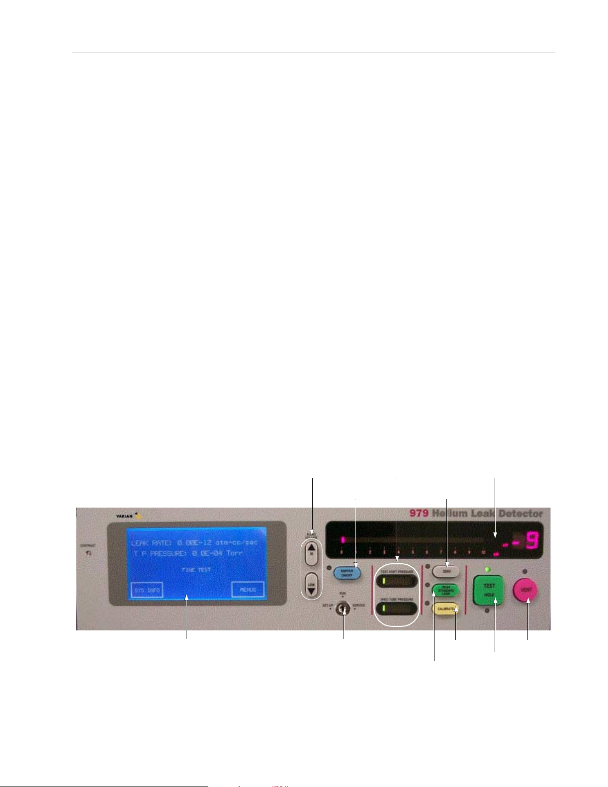
1.1 Front Panel Displays and Controls
The 979 front panel leak rate display and control buttons are locat ed on the front right-hand
side of the leak detector (Figure 1-1). The panel features large, color coded and clearly
labeled buttons, and a large, easy to read bar graph display.
A touch panel display for the initial setup and configuration of the leak detector is located
on the left of the front panel. The touch panel menus also include some service operations.
If you need additional information abo ut operations of the 979, see the Model 979
Instruction Manual.
Audio Volume
Control
Sniffer
On/Off
Pressure
Displays
Zero
Leak Rate
Display
DRAFT 1/27/03
Touch
Panel
Figure 1-1 979 Front Panel Displays and Controls
Key
Switch
Standard
Read
Leak
Calibrate
Vent
Test/Hold
1-1
Page 28

1.1.1 Key Switch
The 979 Key Switch allows three different levels of access to the touch panel system
controls—RUN, SET-UP or SER VICE. Two di fferent keys are provi ded with the le ak detector :
❑ Key T009 operates the switch in RUN, SET-UP or SERVICE positions.
The T009 key is intended for service personnel and those who are very familiar with
the operation of the unit. Operations such as manually chang ing th e valv es can only
be performed when the key switch is in the SERVICE position. No changes to the
operating parameters are allowed when the key switch is in the RUN position.
❑ Key T008 operates the switch in either the RUN or SET-UP positions.
The T008 key is intended for use by a line supervisor or engineer and allows most
parameters to be changed, but does not allow any operation that could damage the
unit. No changes to the operating parame ters are allowed when the key switch is in
the RUN position.
Model 979 Helium Mass Spectrometer Leak Detector
DRAFT 1/27/03
1-2
Page 29
Model 979 Helium Mass Spectrometer Leak Detector
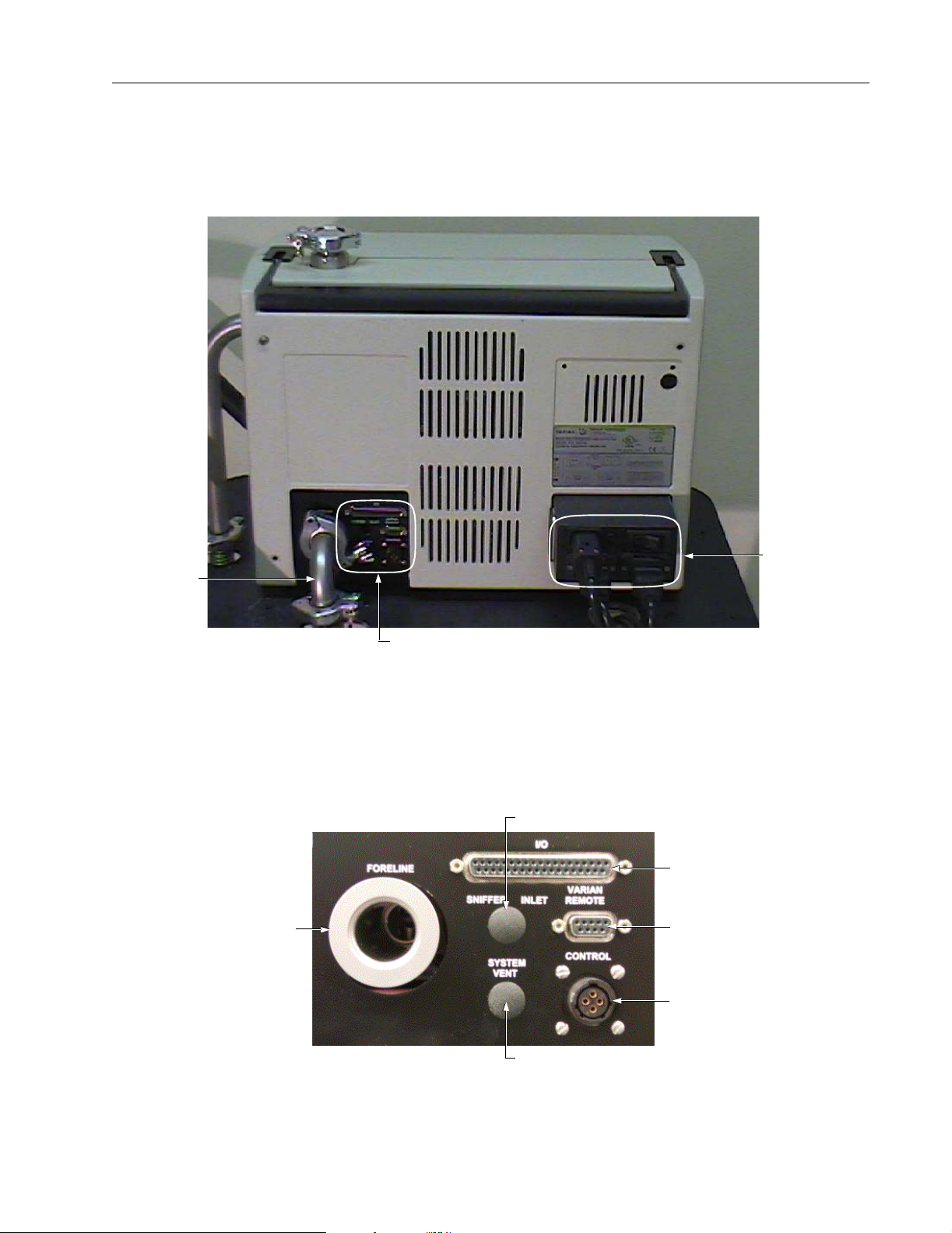
1.2 Rear Panel
The rear panel of the 979 (Figure 1-2) includes power and communications connections as
well as a manifold for connection to a mechanical pump.
Foreline
Pump
Connection
Communication Connections
Figure 1-2 979 Rear Panel
1.2.2 System Control and Communication Panel
The system control and communication panel (Figure 1-3) is located on the lower left
section of the rear panel.
Sniffer Inlet
Foreline Pump
Connection
Power
Connections
DRAFT 1/27/03
I/O Connector
Remote Control Input
Roughing Valve /
Compression Box
Control
System VentPort
Figure 1-3 979 System Control and Communication Panel
1-3
Page 30
Model 979 Helium Mass Spectrometer Leak Detector
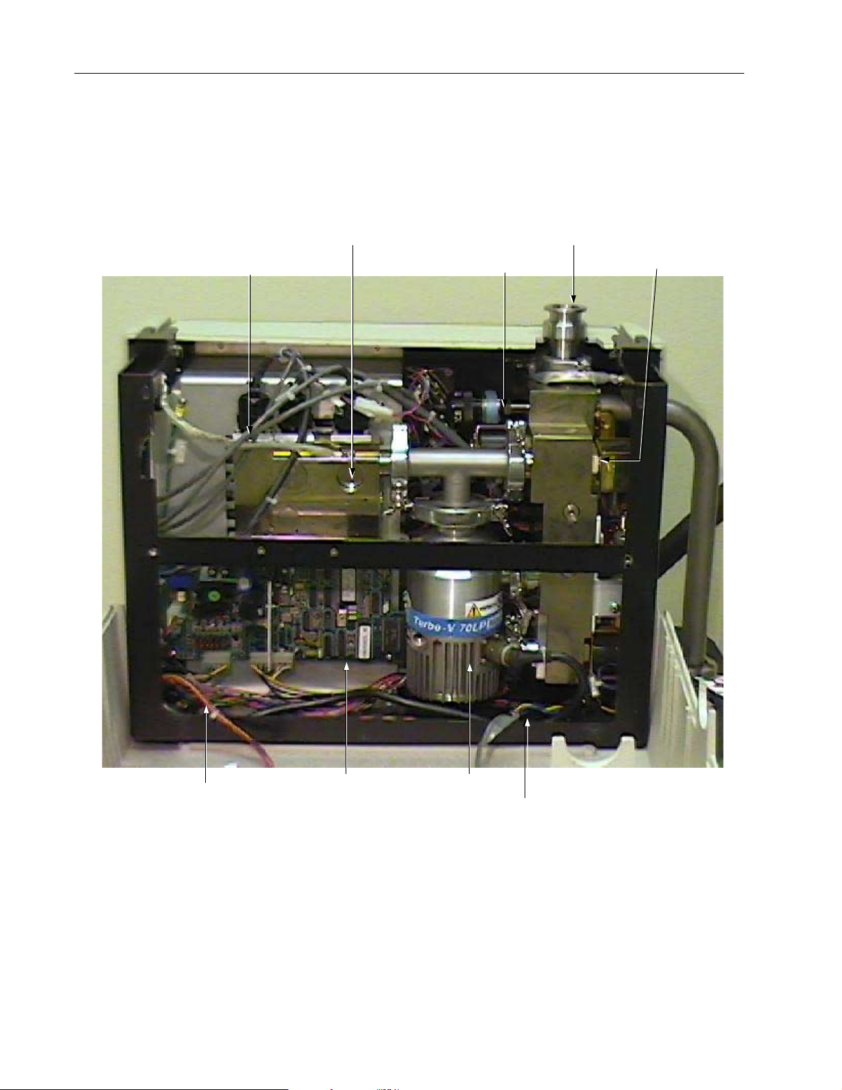
1.3 Inside the Model 979
1.3.1 Inside Front View
Most serviceable parts are accessed from the front of the leak detector (Figure 1-4).
Spectrometer Tube
Ground Strap
Spectrometer
Tube
Thermocouple
Gauge
Test
Port
Valve Block
DRAFT 1/27/03
(to Touch Screen Panel Assembly) (to Inside Front Panel)
1-4
Front Panel
Display Harness
Turbo
Controller Board
Turbo Pump
Ground Strap
Figure 1-4 979 Interior: Front View
Page 31

Model 979 Helium Mass Spectrometer Leak Detector
1.3.2 Side View — Card Cage Side
The left side of the 979 provides access to the card cage (Figure 1-5).
Card Cage
Front Side
of Unit
Card Cage
Bracket
Figure 1-5 979 Interior: Side View Card Cage
DRAFT 1/27/03
1-5
Page 32

Model 979 Helium Mass Spectrometer Leak Detector
1.3.3 Side View — Calibrated Leak, Valve Block Side
The right side of the 979 allows access to the Internal Calibrated Leak (option) (Figure 1-6).
Internal
Calibrated
Leak
Figure 1-6 979 Interior: Side View Valve Block and Internal Calibrated Leak
1.3.4 Rear View
DRAFT 1/27/03
There are no field serviceable part s on the back of the 979 under the rear panel.
Cal Leak
Valve Block
Assembly
Swagelok Fitting
1-6
Page 33

Model 979 Helium Mass Spectrometer Leak Detector
Section 2. Cleaning the Test Port
The test port is located on the outside of the Model 979 leak detector. Therefore, it is not
necessary to turn the leak det ector off or dis con n ect it from main s po w e r if this is the only
procedure being performed. If you are cleaning the test port in conjunction with other
procedures that require opening the leak detector, be sure to turn the leak detector off and
disconnect it from mains power.
The NW25 uses the blank-of f flange ca p on top of the cen tering ring when t he sys tem is not
in use or when in use but not connected to a device.
To clean the test port:
1. Turn the test port wing nut counterclockwise to loosen it (Figure 2-1), remove the quick
clamp (Varian p/n KQ25AWP) from the test port, and remove any connected devices.
CAUTION Be careful not to drop the test port blank-off flange cap when
you remove the test port tightening nut. It is deceptively heavy
for its size.
Test Port
Blank-off Flange Cap
Test Port
Tightening
Nut
Figure 2-1 Test Port with Blank-Off Flange Cap
DRAFT 1/27/03
2-1
Page 34

Model 979 Helium Mass Spectrometer Leak Detector
2. Remov e the test port blank-off flange cap and/or centering ring from the top of the test
port (Figure 2-2).
Figure 2-2 Centering Ring with O-ring
3. Remov e the O-ring from the centering ring.
4. Ex amine the O-ring for wear.
If necessary, use a new O-ring, otherwise clean the O-ring.
NOTE Varian Vacuum Technologies recommends replacing all
O-rings during routine maintenan ce or during any maintenance
procedure requiring that O-rin gs be removed.
DRAFT 1/27/03
5. Examine all parts of the test port, including inside the test port.
6. Pl ace the O-ring into the groove of the centering ring.
CAUTION Remove O-rings carefully with your fin gers. Do not use metal
tools for this task. This prevents scratching of any sealing
surfaces.
Do not use alcohol, methanol or other solvents on O-rings. To
do so causes deterioration and reduces their ability to hold a
vacuum.
Wipe all O-rings clean with a lint-free cloth before installation
to ensure tha t n o fo r ei gn matter is pr es e n t to im p air the seal.
If applicable, apply a small amount of Apiezon L grease and
wipe the O-ri n g s “shiny” dry.
In necessary, use a V acuSolv wipe to remove any dirt or foreign matter and allow parts
to air dry.
2-2
Page 35

Model 979 Helium Mass Spectrometer Leak Detector
7. Pl ace the centering ring onto the top of the test port (Figure 2-3).
Figure 2-3 O-ring and Centering Ring on Test Port
8. Replace the blank-off flange cap or connected device.
9. Rep lace the quic k clamp onto the test port and ti ghten the wing nut clockwise unt il it is
just tight enough to stay in place.
Figure 2-4 shows the system with a connected device.
Figure 2-4 Test Port with Connected Device
DRAFT 1/27/03
2-3
Page 36

Model 979 Helium Mass Spectrometer Leak Detector
DRAFT 1/27/03
This page intentionally left blank.
Page 37

Model 979 Helium Mass Spectrometer Leak Detector
Section 3. Removing the Covers from the 979
There are three main covers that encl ose the Model 979 leak detector:
❑ Front Panel
❑ Rear Panel
❑ Left Side Panel
The front and rear panels can be removed independently of each other. If you have to
remove the side panel to get to the card cage, you mus t remove the front panel, the rear
panel and the side panel in that order.
3.1 Opening the Front Panel
To open the Model 979 front panel:
Front Panel
Screw
1. Di sconnect the mains power supply and make sure all pumps are off.
WARNING Disconnect power from the 979 before performing any
maintenance procedure that requires physically disconnecting
any part of the system.
2. Remov e the 2 Phillips screws from the 979 front panel (Figure 3-1).
DRAFT 1/27/03
Front Panel
Screw
Figure 3-1 979 Front Panel
3-1
Page 38

Model 979 Helium Mass Spectrometer Leak Detector
3. Lean the top of the front panel forward.
CAUTION Be careful not to place tension on the front panel display PCB
harness.
4. I f it is not already supported on a bench, support the front panel with one hand and
press the release tab on the white molex connector (Figure 3-2) located on the touch
panel assembly and pull it to disconnect the PCB harness.
DRAFT 1/27/03
Molex
Connector
Figure 3-2 Molex Connector on Touch Panel Assembly
3-2
Page 39

Model 979 Helium Mass Spectrometer Leak Detector
3.2 Removing the Front Panel
To remove th e front panel:
1. Open the front panel as described in Section 3.1 “Opening the Front Panel”.
The ground strap, which must be removed, is located in the right bottom corner of the
front panel (Figure 3-3).
Front Panel
Ground Strap
Figure 3-3 Front Panel Ground Strap
2. Usi ng a 11-32 nut driver, remove the 8-32 nut that holds the ground strap (Figure 3-4).
Figure 3-4 Ground Strap Removal from Front Panel
DRAFT 1/27/03
3-3
Page 40

Model 979 Helium Mass Spectrometer Leak Detector
3. I f it is not already supported on a bench, support the front panel with one hand and lift
the ground strap up and away from the screw post it is on.
4. Remove the front panel and place it in a safe place where damage cannot occur to the
front panel displays, buttons, or to the touch panel assembly PCB located inside the
front panel.
CAUTION Although the Touch Screen Panel is made of i ndustrial-strength
glass and is high ly durable, it ca n be br oken if it is hit sharply.
DRAFT 1/27/03
3-4
Page 41

Model 979 Helium Mass Spectrometer Leak Detector
3.3 Removing the Rear Panel
To perform this procedure:
1. Di sconnect the mains power supply and make sure all pumps are off.
WARNING Disconnect power from the 979 before performing any
maintenance procedure that requires physically disconnecting
any part of the system.
2. Remov e the 4 l ar g e P hilli ps screws l ocat ed on ea ch corn er of t he rear panel (Fi gur e 3-5).
Handle
Screws
Figure 3-5 Rear Panel Removal
3. Li ft the handle up.
4. Remove the panel and put it in a safe place.
Screws
DRAFT 1/27/03
3-5
Page 42

Model 979 Helium Mass Spectrometer Leak Detector
3.4 Removing the Side Panel
To remove the side panel:
1. Open and remove the fron t panel as descr ibed in Secti on 3.1 “Opening the Front Panel”
on page 3-1 and Section 3.2 “Removing the Front Panel” on page 3-3.
2. Remov e the rear panel as described in Section 3.3 “Removing the Rear Panel” on
page 3-5.
3. Bac k out one of the silver Phillips screws on the black vented side panel (Figure 3-6).
Silver Screw
4. Slide the screw toward th e ce n te r of the panel.
5. Support the panel with one hand and back out the other screw on the side panel.
DRAFT 1/27/03
6. Slide the screw toward the center, moving the latch from under the chassis.
7. Place the panel where it will not get damaged.
Silver Screw
Figure 3-6 Side Panel Removal
This moves the latch from under the chassis and dis engages this side of the panel.
The panel disengages, completel y exposing the card cage.
3-6
Page 43

Model 979 Helium Mass Spectrometer Leak Detector
3.5 Replacing All Covers and Panels
Each of the pro c edures in thi s se ction is comp l e te for its state d p u rp o se. If all pane l s an d
covers have been removed, however, they must be replaced in the order given in this
procedure.
3.5.1 Replacing the Side Panel
To replace the side panel:
1. Pl ace the panel on the side with the card cage oriented so the screws are up and facing
you.
2. Support the panel and insert a Phillips screwdriver into one of the silver screws.
3. Sl ide the screw toward the outside of the panel to move the latch under the chassis.
4. Tighten the screw.
5. Repeat for the other side of the panel.
3.5.2 Replacing the Rear Panel
To replace the rear panel:
1. Place the rear panel onto the chassis, fitting the top under the port nut.
2. Replace and tight e n the 4 Phillips sc rews locate d in each corner of the panel.
3.5.3 Replacing the Front Panel
To replace the front panel:
1. Support the panel with one hand, if it is not already supported on a bench.
2. Align the bottom of the panel with the bottom of the leak detector, leaving it propped
open.
3. Place the grounding strap over the screw post.
4. Pl ace the 8-32 nut onto the screw post and tighten it using an 11-32 nut driver.
DRAFT 1/27/03
3-7
Page 44

Model 979 Helium Mass Spectrometer Leak Detector
5. Lift the panel towards the leak detector and insert the white PCB harness molex
connector plug into the connector located on the touch panel PCB assembly
(Figure 3-7).
NOTE Be sure the white PCB harness molex connector plug clicks int o
place securely.
DRAFT 1/27/03
6. Rai se the panel until it is closed, f itting the top unde r the port nut and maki ng sure that it
7. Replace and tighten the 2 Phillips screws on the front of the panel.
PCB Harness
Connector
Figure 3-7 Front Panel PCB Harness Connector
CAUTION Be careful not to place tension on the front panel display PCB
harness.
fits securely with the rear panel, and that it is not pinching any wires.
3-8
Page 45

Model 979 Helium Mass Spectrometer Leak Detector
Section 4. The Internal Calibrated Leak
4.1 Recalibrating the Internal Calibrated Leak
Helium calibrated leaks typically degrade at 3 percent per year. The calibrated leak
supplied with your 979 must be checked at least on ce a year to ensure it is at the value
stated on its tag. Failure to che ck the leak could res ult in unreli able testi ng. You can arrange
for testing and recalibration at a lab of your choice.
Varian Vacuum Techn ologies provides NIST-traceable calibrated leak testing and
verification services. You can contact Customer Service at 1-800-8VARIAN to arrange for
recalibration.
4.2 Replacing the Internal Calibrated Leak
The Internal Calibrated L eak is located su ch that the Valve Block Coil and Plun ger Assembly
must be removed (Figure 4-1) to have room to remove the calibrated leak.
Internal
Calibrated Leak
V alve Block
Coil & Plunger
Assembly
Figure 4-1 979 Side View: Removal of Valve Block Coil and Plunger Assembly
CAUTION If the Gross Le ak o pt io n is installed:
(1) Do not make any alterations to the Gross Leak. Do not touch
the knurled nut on the Gross Leak.
(2) The Gross Leak is calibrated at the factory and if any
alteration is made, the Gross Leak must be returned to the
factory for recalibration. For returns, contact Varian Vacuum
Technologies Customer Service at 1-800-8VARIAN.
DRAFT 1/27/03
4-1
Page 46

Model 979 Helium Mass Spectrometer Leak Detector
4.2.1 Removing the Valve Block Coil and Plunger Assembly
To remove the Valve Block Coil and Plunger Assembly:
1. Di sconnect the mains power supply and make sure all pumps are off.
WARNING Disconnect power from the 979 before performing any
procedure that requires physi cally disconnectin g any part of the
system.
2. Open the front and rear panels (Figure 4-2) as described in Section 3.1 “Opening the
Front Panel”.
DRAFT 1/27/03
Internal
Calibrated Leak
End Cap
Valve Stem
Valve Block
Coil & Plunger
Assembly
Valve Power Connections
Figure 4-2 979 Side View
CAUTION Use powder-free butyl or polycarbonate gloves to prevent skin
oils from getting on vacuum surfaces.
4-2
Page 47

Model 979 Helium Mass Spectrometer Leak Detector
3. Loosen and remove the end cap from the valve stem (Figure 4-3) using a 9-16 wrench.
NOTE Be careful not to drop or lose the black sleev e located inside
the end cap.
End Cap
Valve Stem
Figure 4-3 End Cap and Valve Stem
Figure 4-4 shows the Valve Stem with the end cap removed.
Figure 4-4 Valve Stem with End Cap Removed
DRAFT 1/27/03
4-3
Page 48

Model 979 Helium Mass Spectrometer Leak Detector
4. Use a 9-16 wrench to loosen the valve stem (Figure 4-5), then rotate the connection
counterclockwise until you hit the stop.
Reposition the wrench and repeat. When it is loose enough, you can finish removing it
by hand.
5. Di sconnect th e 2 pink v alv e block power con nectors ( Figure 4-6), labeled V7, th at have
DRAFT 1/27/03
Figure 4-5 Valve Stem Removal
black and yellow wires.
Power Connectors
Figure 4-6 V7 Valve Block Power Connector Removal
4-4
Page 49

Model 979 Helium Mass Spectrometer Leak Detector
6. Bei ng careful not to scratc h the valve block, insert a lo ng slotted screwdriver thro ugh the
top of the leak detector down to the slotted post on the top of the coil and plunger
assembly (Figure 4-7).
Figure 4-7 Slotted Post on Coil and Plunger Assembly
7. Hol ding the coil with one hand so it doesn’t spin (Figure 4-8), loosen the coil and
plunger assembly using the long slotted screwdriver.
Figure 4-8 Securing the Coil to Loosen Plunger Assembly
CAUTION The plunger is located on the bottom of the coil and plunger
assembly . I t has a spring. Be care ful not to drop th e plunger into
the leak detector.
DRAFT 1/27/03
4-5
Page 50

Model 979 Helium Mass Spectrometer Leak Detector
8. Li ft the coil and plunger assembly away from the cal leak valve block, and slip your
other hand or finger under the bottom of the assembly so the plunger that is located at
the bottom of th e coil does not fall.
9. Place the coil and plunger assembly aside.
Once the coil and plunger assembly is removed, the calibrated leak can be removed. Refer
to Section 4.2.4 “Examining and Cleaning the Valve Block Coil and Plunger Assembly” on
page 4-11 before re assembling.
4.2.2 Removing the Internal Calibrate Leak
To remove the Internal Calibrated Leak:
CAUTION Handle the calibrated leak carefully. It is a delicate piece of
equipment that contains a glass liner that can break if it is
dropped or hit sharply.
1. Remove the 2 large Phillips screws that hold the calibrated leak straps (Figure 4-9).
Leak Strap
and Screw
Leak Strap
and Screw
DRAFT 1/27/03
Swagelok
Fitting
Brass Valve Block
Figure 4-9 979 Side View: End Cap, Valve Stem, and Coil and Plunger Assembly Removed
4-6
Page 51

Model 979 Helium Mass Spectrometer Leak Detector
2. Remove the straps by sliding them up and over the top of the calibrated leak.
3. Hol d the flats of t he nut on the swagel ok fittin g (elbow) below the cal ibrated lea k with a
crescent wrench (Figure 4-10).
Compression Box
Logic Connection
Figure 4-10 Elbow Flat Secured with Crescent Wrench
NOTE Figure 4-10 (and others that follow) show the side panel of a
leak detector that is using a dry pump. It is connected to a
compression box and the wire supplies val ve lo gic . If your l eak
detector is not a dry configuration, you will not use a
compression box and will not see this connection.
4. Usi ng a 13- 16 op en wrench, pl ace it on the flat s of the cal ibrat ed leak (F igu re 4-11) and
rotate the leak counterclockwise until you hit the stop.
DRAFT 1/27/03
Figure 4-11 Loosening Leak with Open Wrench
4-7
Page 52

Model 979 Helium Mass Spectrometer Leak Detector
5. Reposition the wrench and repeat this action until the leak is loose enough to fi nish
loosening it by hand (Figure 4-12).
Figure 4-12 Removal of Calibrated Leak
CAUTION Handle the calibrated leak carefully. It is a delicate piece of
equipment that contains a glass liner that can break if it is
dropped or hit sharply.
6. Li ft the calibrated leak up and off of the elbow.
7. Det ermine which replacement plan you have, and take the appropriate action:
DRAFT 1/27/03
❑ Return the leak to Varian for recalibration
❑ Return the leak to Varian for replacement as part of the replacement program
❑ Send the leak to the NIST lab of your choice for recalibration
4-8
Page 53

Model 979 Helium Mass Spectrometer Leak Detector
4.2.3 Replacing the Internal Calibrated Leak
To replace the internal calibrated leak:
CAUTION Be careful not to get any Locti te PST 565 into the valve or in the
small hole in the valve. The valve can become plugged,
resulting in unreliable leak detection.
The threads of the swagelok fitt ing that the calibrated leak connects to will have the
remnants of Loctite PST 565 Thread Seala n t (Figure 4-13).
1. Cl ean the threads using acetone or isopropyl alcohol, or a VacuSolv wipe or VacuSolv
liquid on a lint-free cloth.
Allow to air dry before proceeding to the next step.
Threads with
Loctite Remnants
Figure 4-13 Elbow after Removal of Calibrated Leak
2. Bei ng careful not to get any in the valve, place a small amount of Loctite PST 565
Thread Sealant onto the first two threads of the swagelok fitting.
3. Place the internal calibrated leak onto the swagelok fitting and hand tighten.
DRAFT 1/27/03
4-9
Page 54

Model 979 Helium Mass Spectrometer Leak Detector
4. Position a crescent wrench on the flats of the swagelok fitting (Figure 4-14), hold it still
and finish tightening the calibrated leak using a 13-16 open wrench.
Be sure the calibrated leak is oriented so that information on the label can be read
without having to disturb it.
5. Pl ace the holding straps over the top of the calibrated leak and position them so the
DRAFT 1/27/03
Figure 4-14 Connecting Leak with Open Wrench
CAUTION Be careful not to overtighten t he leak, but be sure the ca librated
leak is completely seated on the swage lok fitting.
ends are over the screw holes (Figure 4-15).
4-10
Figure 4-15 Calibrated Leak Strap Replacement
6. Insert the screws and tig h ten them com pl e tely.
Page 55

Model 979 Helium Mass Spectrometer Leak Detector
4.2.4 Examining and Cleaning the Valve Block Coil and Plunger Assembly
The various parts of the Valve Block Coil and Plunger Assembly must be examined and
cleaned before reassembling the valve.
4.2.4.1 Examining and Cleaning the Cal Leak Valve Block
To examine and clean the cal leak valve block:
1. Locate the O-ring inside the cavity of the cal leak valve block that accepts the coil and
plunger assembly.
NOTE If possible, replace O-rings during routine maintenance or
during maintenance procedures that requiring the removal of
O-rings.
CAUTION Do not use a metal instrument to remove the O-ring.
Do not use alcohol, methanol or other solvents on O-rings. To
do so causes deterioration and reduces their ability to hold a
vacuum.
Always wipe O-rings with a lint -f ree clot h bef ore instal la tion to
ensure that no foreign matter is present to impair the seal.
If applicable, apply a small amount of Apiezon L grease and
wipe the O-ri n g s “shiny” dry.
2. Carefully remove the O-ring, and examine it for dirt and wear.
3. If the cavity is dirty, use a lint-free cloth or VacuSolv wipe to clean it and allow it to air
dry.
4. Place the O-ring into the cavity and verify that it is fully seated.
DRAFT 1/27/03
4-11
Page 56

Model 979 Helium Mass Spectrometer Leak Detector
4.2.4.2 Examining and Cleaning the Coil and Plunger Assembly
The plunger has elastomer at the top and at the bottom. This elastomer helps to form the
seal when the valve closes. It must be kept clean and free of debris. Do not use any sol vent
that will dry out the elastomer.
CAUTION Do not use alcohol, methanol or other solvents on the
elastomer parts of the plunger. To clean it, wipe with a dry
lint-free cloth only.
To examine and clean the coil and plunger assembly:
1. Pul l the plunger out of the coil, being careful not to drop any part.
2. Ex amine the top of the plunger for wear and debris (Figure 4-16).
3. Wipe it clean using a dry lint-free cloth.
DRAFT 1/27/03
4-12
Figure 4-16 Top of Plunger
Page 57

Model 979 Helium Mass Spectrometer Leak Detector
4. Ex amine the bottom of the plunger (Figure 4-17) for wear and debris and wipe off any
debris using a dry lint-free cloth, being careful not to lose the spring.
Figure 4-17 Bottom of Plunger
5. Examine the cavity of the coil making sure it is clean and that the small hole is not
plugged.
6. Wipe the cavity using a cotton swab that has been dipped in isopropyl alcohol.
7. Place the plunger back into the coil.
4.2.4.3 Examining and Cleaning the Valve Stem and End Cap
To examine and clean the valve stem and end cap:
1. Examine the valve stem inside and out.
2. Bl ow compr essed air through the valve stem to be sure it is not blocked.
3. Wipe the outside of the valve stem clean using a lint-free cloth or, if necessary, using
Vac u So l v, and allow it to air dry.
4. Repeat step 3 for the end cap.
DRAFT 1/27/03
4-13
Page 58

Model 979 Helium Mass Spectrometer Leak Detector
4.2.5 Replacing the Coil and Plunger Assembly
The final steps of replacing the internal calibrated leak include replacing the coil and
plunger assembly, the valve stem, and the end cap.
To replace the coil and plunger assembly:
1. If it is not there already, place the plunger into the coil.
2. Hold the coil and plunger assembly with one finger placed to hold the plunger in place.
CAUTION If you press the spring and inadvertently let it go, the plunger
could shoot into the leak detector. Do not press the spring, just
hold it in place.
3. Tu rn the coi l and plung er a sse mbly ove r, place it into the cal lea k valve bl ock, and hold
it upright. (Figure 4-18).
DRAFT 1/27/03
4-14
Figure 4-18 Placement of Plunger Assembly into Coil
CAUTION Take care not to bump the sides to avoid getting small metal
chips on the O-ring.
Page 59

Model 979 Helium Mass Spectrometer Leak Detector
4. Carefully thread the coil by hand until it is tight enough to be held on its own.
5. Bei ng careful not to scratc h the valve block, insert a lo ng slotted screwdriver thro ugh the
top of the leak detector down to the slotted post (Figure 4-19) on the top of the coil and
plunger assembly.
6. Hold the coil in place w ith o n e h a nd so it doesn’t spin, position the coil so that the
terminals are angled out (Figure 4-19) to receive the power connections, and turn the
post using the screwdriver until the plunger assembly is secured.
Do not overtighten.
Power
Terminals
Figure 4-19 Coil and Plunger A ssembly Replacement
7. Pl ace the val ve stem onto t he post on the top of t he coil (Fi gure 4-20) and tighten it until
the valve stem is snug.
Figure 4-20 Positioning Valve Stem onto Coil and Plunger Assembly
The top fitting should be angled out towards the side so it can be accessed, but not so
far out that it interferes with the covers being replaced (Figure 4-21 on page 4-16).
DRAFT 1/27/03
4-15
Page 60

Model 979 Helium Mass Spectrometer Leak Detector
8. Pl ace the end cap onto the valve stem and using a 9-16 wrench tighten it until it is just
snug (Figure 4-21).
Valve Stem
End Cap
Figure 4-21 End Cap Replacement
9. Rec onnect the valve block connections labeled V7, placing the connector with the
yellow wire onto the upper connection and the connector with the black wire onto the
lower connection.
10. Replace the rear and front pan els as descri bed in Sectio n 3.5 “Replacing All Covers and
11. Reconnect mains power .
12. Turn on the leak detector power switch.
13. When the pumps are up to speed and warmed up, enter the value of the new internal
DRAFT 1/27/03
14. Calibrate the 979 using the procedure described in Sec tion 9.1 “Calibrate the 979” on
15. Leak check the assembly before using the 979 for testing.
Panels” on page 3-7.
calibrated leak, i f it is different than the one that was ju st removed, using the CAL LEAK
SET-UP screen.
NOTE If you need additional information about entering the value of
the internal calibrat ed leak or performing a calibration, see the
Model 979 Instruction Manual.
page 9-1.
Refer to Section 10 “Leak Checking for Reliability”.
4-16
Page 61

Model 979 Helium Mass Spectrometer Leak Detector
Section 5. Spectrometer Tube Assembly
5.1 Spectrometer Tube Exchange
The entire spectrometer tube, including preamplifier, ion source and Button TC, can be
replaced as one unit.
NOTE Rebuilt spectrometer tube s are available from Varian Vacuum
Technologies on an exchange basis. Contact Varian Vacuum
Technologies Customer Service at 1-800-8VARIAN for details.
CAUTION Use powder-free butyl or polycarbonate gloves to prevent skin
oils from getting on vacuum surfaces.
5.1.1 Removing the Spectrometer Tube Assembly for Complete Exchange
To remove and replace the spectrometer tube as sembly:
1. Di sconnect the mains power supply and make sure all pumps are off.
WARNING Disconnect power from the 979 before performing any
maintenance procedure that requires physically disconnecting
any part of the system.
The spectrometer tube operates at a very high vacuum produced by the high vacuum
pump. Service of the spectrometer tube requires that this vacuum be vented to the
atmosphere.
2. Open th e front panel as described in Section 3.1 “Opening the Front Panel” on page 3-1
and remove the spectrometer tube.
It is not necessary to remove the fr ont panel complet ely, however take care not to place
tension on the front panel display PCB harness.
DRAFT 1/27/03
5-1
Page 62

Model 979 Helium Mass Spectrometer Leak Detector
3. Vent the spectrometer tube (Figure 5-1) by turning the knurled nut on the turbo pump
(knurled nut not shown in this view) approxima tely 1/4 turn counterclockwise.
Spectrometer
Tube
Turbo Pump
(Knurled Nut is not
showninthisview.)
Figure 5-1 Spectrometer Tube and Turbo Pump
4. Remov e the three connect ors from the top of the spect rometer tube shown in Figure 5-1
5. Repeat Step 4 for each connector.
6. I f the connector cables are not labeled, label them now.
DRAFT 1/27/03
In addition to the three connectors on the top of the unit (Figure 5-2) and the ground
cable, the spectrometer tube is attached by an NW-25 quick clamp and a wing nut
located below the tube (not shown in this vi ew).
by grasping the plug and gently pulling it straight up and off of the contact pins
(Figure 5-2).
The connector cables are labeled SYSTEM, ION SOURCE, and PRE-AMP.
CAUTION Be sure to grasp the plug and not just the cable. Pulling on the
cable to remove the connector could damage the cable.
5-2
Page 63

Model 979 Helium Mass Spectrometer Leak Detector
Ground Cable
and Screw
Figure 5-2 Ground Cable and Screw for Removing Connectors
7. Di sconnect the ground cable (Figure 5-2) from the spectrometer tube by removing the
screw using a slotted screwdri ver.
8. Taking care n ot t o damag e th e turbo pu mp control ler PCB l ocat ed und erneath the shelf,
remove the wing nut, locking washer and flat washer located underneath the shelf
below the spectrometer tube (Figure 5-3).
DRAFT 1/27/03
This page intentionally left blank.
Wing Nut
Figure 5-3 Wing Nut Under Shelf
Page 64

Model 979 Helium Mass Spectrometer Leak Detector
9. Remov e the NW-25 quick clamp to disconnect the spectrometer tube from the
turbo-to-spec tube manifol d (Figure 5-4).
Win
g
Figure 5-4 NW-25 Quick Clamp on Turbo-to-Spec Tube Manifold
10. Lift the spectrometer tube assembly off of the shelf and lay it down on a clean
11. Using a 5-64 Allen wrench, remove the 8-32 threaded stud with Teflon stando ff from
DRAFT 1/27/03
12. Remove the centering ring and O-ring from the spectrometer tube flange end.
non-magnetic surface.
CAUTION If the spectro m e te r tu b e magnet com e s in co n ta c t w i th a
magnetic surface, the magnet may lose its gauss causing the
spectrometer tube to lose sensitivity.
the spectrometer tube and place it on a clean surface.
5-4
Page 65

Model 979 Helium Mass Spectrometer Leak Detector
5.1.2 Examining and Cleaning the Centering Ring and O-Ring
To examine and clean the centering ring and O-ring:
1. Ex amine the centering ring, wipe it clean using a VacuSolv wipe, and let it air dry.
2. Car efully inspect the O-ring (Figure 5-5), and if damaged, replace it.
NOTE When possible, replace all O-ri ngs during rout ine maintenance
or during maintenance procedures that require the removal of
O-rings.
CAUTION Remove O-rings carefully with your fingers. Do not use metal
tools for this task. This prevents scratching of any sealing
surfaces.
Do not use alcohol, methanol or other solvents on O-rings. To
do so causes deterioration and reduces their ability to hold a
vacuum.
Do not use grease or ot her subs ta nce on O-ri ngs that will c ome
in contact with the spectrometer tube.
Figure 5-5 O-ring Inspection
3. Before reusing O-rings or installing new O-rings, wipe them down with a lint-free cloth
to ensure tha t no fo reign matte r is pr esent to impair the seal.
4. Place the O-ring on the centering ring.
DRAFT 1/27/03
5-5
Page 66

Model 979 Helium Mass Spectrometer Leak Detector
5.2 Reinstalling the Spectrometer Tube
To reinstall the spectrometer tube:
1. Pl ace the 8-32 threaded stud with Teflon standoff into the bottom of the spectro meter
tube and tighten it using a 5-64 Allen wrench.
2. Pl ace the spectrometer tube assembly onto the shelf with the flange end facing the
manifold elbow and the threaded stud inserted into the hole in the shelf.
3. Insert the centering ring and O-ring onto the spectrometer tube.
4. At tach the spectrometer tube to the turbo-to-spec tube manifold, replace the NW-25
quick clamp, and tighten the wing nut fully.
5. Place the washer, lock washer, and wing nut onto the threaded stud and tighten it fully.
6. Place the ground cable onto the spectrometer tube and fasten it with the slotted screw.
7. Replace the connectors, being sure to replace each one onto its proper item.
If they are labeled, place the connect or labeled:
❑ SYSTEM on the Button TC
8. Close the vacuum by tightening the knurled nut on the turbo pump.
9. Cl ose the front panel as described in Section 3.5 “Replacing All Covers and Panels” on
10. Connect the pump power plugs to the rear panel if they are not connected already.
DRAFT 1/27/03
11. Connect mains power.
12. Turn the leak detector on and wait for the system to be ready.
13. Allow the pumps to warm up if the detector has been off for some time.
14. Perform the system pressure gauge calibration described in Section 9.3.1 “System
15. Calibrate the 979 using the procedure described in Sec tion 9.1 “Calibrate the 979” on
16. Leak check the assembly before using the 979 for testing.
❑ ION SOURCE onto the ion source
❑ PRE-AMP onto the preamplifier
The connectors and the center posts are keyed to go on only one way.
page 3-7.
Pressure Gauge Calibration Procedure” on page 9-7.
page 9-1.
Refer to Section 10 “Leak Checking for Reliability”.
5-6
Page 67

Model 979 Helium Mass Spectrometer Leak Detector
5.3 Removing the Button Thermocouple from the
Spectrometer Tube
It is not necessary to remove the front panel completel y or disconnect the spectrometer tube
to remove the Button Thermocouple (Button TC).
CAUTION Do not place tension on the front panel display PCB harness.
CAUTION Use powder-free butyl or polycarbonate gloves to prevent skin
oils from getting on vacuum surfaces.
To perform this procedure:
1. Di sconnect the mains power supply and make sure all pumps are off.
WARNING Disconnect power from the 979 before performing any
maintenance procedure that requires physically disconnecting
any part of the system.
2. Open the front panel as described in Section 3.1 “Opening the Front Panel” on
page 3-1.
3. Vent the spectrometer tube (Figure 5-6) by turning the knurled nut on the turbo pump
(knurled nut not shown in this view) approxima tely 1/4 turn counterclockwise.
Button TC
Spectrometer
Tube
DRAFT 1/27/03
Turbo Pump
(Knurled Nut is not
shown in this view.)
Figure 5-6 Button TC, Spectrometer Tube, and Turbo Pump
5-7
Page 68

Model 979 Helium Mass Spectrometer Leak Detector
4. Remove the connector labeled SYSTEM from the top of the Button TC (Figure 5-7) by
grasping the plug of the connec tor and gentl y pulling i t stra ight up and off of the con tact
pins.
If the cable is not labeled, label it now.
5. Remov e the 4 Phillips screws that hold the Button TC flange cap (Figure 5-8).
DRAFT 1/27/03
Phillips Screws Phillips Screws
Figure 5-7 Connector Removal
CAUTION Be sure to grasp the plug and not just the cable. Pulling on the
cable to remove the connector could damage the cable.
Figure 5-8 Phillips Screws on Button TC Assembly
5-8
Page 69

Model 979 Helium Mass Spectrometer Leak Detector
6. Remov e the Button TC flange cap (Figure 5-9) by pressing down on the Button TC center
post
and lifting the flange cap up and off of the Button TC.
Flange Cap
Center Post
Button TC Assembly
Figure 5-9 Flange Cap and Center Post on Button TC Assembly
7. I f the flange cap and Button TC come up together, hold one hand under the Button TC
to catch it, and push down on the center post to remove the flange cap from the
Button TC.
8. Ex amine the Button TC and the Button TC chamber. If either is discolored or dirty,
contact Varian Vacuum T echnologies Customer Service at 1-800-8VARIAN.
NOTE If Customer Service recommends a complet e spect rometer tube
overhaul, follow the procedure in Section 5.9 “Spectrometer
Tube Overhaul” on page 5-20.
DRAFT 1/27/03
5-9
Page 70

Model 979 Helium Mass Spectrometer Leak Detector
5.4 Replacing the Button Thermocouple
CAUTION Handle the Button TC carefully (Figure 5-10). The sensing wire
on the bottom side of the TC is approximately 3 mils thick. Care
must be taken not to damage this wire.
Sensing Wire
To replace the Button TC:
1. Hol d the Button TC by the contact pins and insert it carefully into the Button TC cavity
DRAFT 1/27/03
2. Ex amine the flange cap to be sure it is not damaged.
3. Wipe the flange cap with a lint free cloth to be sure it is free of debris.
Figure 5-10 Sensing Wire
NOTE When replacing the preamplifier, ion source, and Button TC,
position the key of the center post to be p erpendicular to the
spectrometer tube body facing the rear. Replace the flange cap
so that the groove is aligned with the two legs on either side of
the key.
in the spectrometer tube body.
Position the key in the center post to be perpendicular to the spectrometer tube body
and facing the rear.
5-10
Page 71

Model 979 Helium Mass Spectrometer Leak Detector
4. Replace the Button TC flange cap so that the grooves (Figure 5-11) in the depress ion of
the flange cap line up with the center post key.
5. I nsert and tighten the 4 Phillips screws.
Flange Cap
Grooves
Figure 5-11 Flange Cap Grooves
6. Place the connector labeled SYSTEM firmly onto the Button TC.
The connector and center post are keyed to go on only one way.
7. Close the vacuum by tightening the knurled nut on the turbo pump.
8. Cl ose the front panel as described in Section 3.5 “Replacing All Covers and Panels” on
page 3-7.
9. Connect the pump power plugs to the rear panel if they are not connected already.
10. Connect mains power.
11. Turn the leak detector on and wait for the system to be ready.
12. Allow the pumps to warm up if the detector has been off for some time.
13. Perform the system pressure gauge calibration described in Section 9.3.1 “System
Pressure Gauge Calibration Procedure” on page 9-7.
14. Calibrate the 979 using the procedure described in Sec tion 9.1 “Calibrate the 979” on
page 9-1.
15. Leak check the assembly before using the 979 for testing.
Refer to Section 10 “Leak Checking for Reliability”.
DRAFT 1/27/03
5-11
Page 72

Model 979 Helium Mass Spectrometer Leak Detector
5.5 Removing the Ion Source
To remove the Ion Source it is not necessary to remove the front panel completely or
disconnect the spectrometer tube. However, take care not to place tension on the front
panel display PCB harness.
CAUTION Use powder-free butyl or polycarbonate gloves to prevent skin
oils from getting on vacuum surfaces.
To remove the ion source:
1. Di sconnect the mains power supply and make sure all pumps are off.
WARNING Disconnect power from the 979 before performing any
maintenance procedure that requires physically disconnecting
any part of the system.
2. Open the front panel as described in Section 3.1 “Opening the Front Panel” on
3. Vent the spectrometer tube (Figure 5-12) by turning the knurled nut on the turbo pump
Ion Source
DRAFT 1/27/03
Spectrometer
page 3-1.
(knurled nut not shown in this view) approxima tely 1/4 turn counterclockwise.
Tube
Turbo Pump
(Knurled Nut is not
showninthisview.)
Figure 5-12 Ion Source, Spectrometer Tube, and Turbo Pump
5-12
Page 73

Model 979 Helium Mass Spectrometer Leak Detector
4. Remov e the connector label ed ION SOURCE from the top of the Ion Sour ce by grasping
the plug of the connector and gently pulling it straight up and off of the contact pins.
If the cable is not labeled, label it now.
CAUTION Be sure to grasp the plug and not just the cable. Pulling on the
cable to remove the connector could damage the cable.
5. Remov e the 4 Phillips screws that hold the ion source flange cap.
WARNING When handling the Ion Source, wear powder-free butyl or
polycarbonate gloves. If you handle the Ion Source with bare
hands, wash them thoroughly, especially before smoking or
eating.
6. Remov e the ion source fl ange cap by pressing down on the ion sour ce center post
lifting the fl an g e ca p up an d off of the ion source.
7. If the flange cap and ion source come up together, hold one hand under the ion source
to catch it and push down on the center post to remove the flange cap from the ion
source.
8. Remov e the ion source from the spectrometer tube body (Figure 5-13).
and
DRAFT 1/27/03
Figure 5-13 Ion Source Removal
5-13
Page 74

Model 979 Helium Mass Spectrometer Leak Detector
9. Examine the ion source (Figure 5-14) and cavity (Figure 5-15) for deposits and
discoloration.
10. If either is discolored or dirty cont act Varian Vacuum Technologies Customer Service at
1-800-8VARIAN.
NOTE Dark carbon-like deposits around the ion source filament and/
or a rainbow-like discoloration on the inside walls of the ion
source cavity indicate that the spectrometer tube has been
operated at too high a pressure. This can occu r from a system
pressure leak or transferring into test at too high a pressure.
If Customer Service recommends a complete spectrometer tube overhaul, follow the
procedure in Section 5.9 “Spectrometer Tube Overhaul” on page 5-20.
11. When examination is complete, dispose of the ion source pr operly or return i t to Varian
Vacuum Technologies for exchange.
12. Locate the ground slit plate in the ion source cavity (Figure 5-15).
13. If this is highly discolored, contact Varian Vacuum Technologies Customer Service at
DRAFT 1/27/03
1-800-8VARIAN.
Alignment Hole
Alignment Pin
Figure 5-14 Alignment Pin
Ground Slit Plate
5-14
Figure 5-15 Alignment Hold and Ground Slit Plate in Ion Source Cavity
If Customer Service recommends a complete spectrometer tube overhaul, follow the
procedure in Section 5.9 “Spectrometer Tube Overhaul” on page 5-20.
Page 75

Model 979 Helium Mass Spectrometer Leak Detector
5.6 Replacing the Ion Source
NOTE It is good practice when replacing the preamplifier, ion source
and Button TC to have the key of the center post line up
perpendicular to the spectr ometer tube body and face t he back.
This alignment happens by defa ult for some of these piece s. It is
also good practice to replace the fla nge cap with the groove
aligned with the two legs on either side of the key.
To replace the Ion Source:
CAUTION A short could result at power up if the alignment pin touc hes
the sides of the alignment hole.
1. Hol ding the ion source by the connector pins, insert the ion source into the cavity so
that its alignment pin falls in the center of the hole in the cavity (Figure 5-16).
CAUTION Be careful not to let the ion source alignment pin touch the
sides of the hole.
NOTE If necessary, hold onto the O-ring (Figure 5-16) so that it seats
properly when you insert the ion source.
DRAFT 1/27/03
Figure 5-16 Ion Source Insertion
5-15
Page 76

Model 979 Helium Mass Spectrometer Leak Detector
2. Rep lace the ion sourc e flange cap so that the grooves in the depression of the flange cap
(Figure 5-17) line up with the legs on either side of the center post.
3. I nsert and tighten the 4 Phillips screws.
Flange Cap
Grooves
Figure 5-17 Alignment of Flange Cap Grooves with Ion Source Center Legs
4. Place the connector labeled ION SOURCE firmly onto the Ion Source.
The connector and center post are keyed to fit only one way.
5. Close the vacuum by tightening the knurled nut on the turbo pump.
6. Cl ose the front panel as described in Section 3.5 “Replacing All Covers and Panels” on
7. Connect the pump power plugs to the rear panel if they are not connected already.
8. Conne ct mains power.
9. Tu rn the leak detector on and wait for the system to be ready.
10. Allow the pumps to warm up if the detector has been off for some time.
11. Calibrate the 979 using the procedure described in Secti on 9.1 “Calibrate the 979” on
DRAFT 1/27/03
12. Leak check the assembly before using the 979 for testing.
page 3-7.
page 9-1.
Refer to Section 10 “Leak Checking for Reliability” for guidelines.
5-16
Page 77

Model 979 Helium Mass Spectrometer Leak Detector
5.7 Removing the Preamplifier
CAUTION The preamplifier is a static sensitive device. Wear a grounding
device while the preamplifier is being handled.
To remove the preamplifier it is not necessary to remove the front panel completely or
disconnect the spectrometer tube. However, take care not to place tension on the front
panel display PCB harness.
CAUTION Use powder-free butyl or polycarbonate gloves to prevent skin
oils from getting on vacuum surfaces.
To remove the preamplifier:
1. Di sconnect the mains power supply and make sure all pumps are off.
WARNING Disconnect power from the 979 before performing any
maintenance procedure that requires physically disconnecting
any part of the system.
2. Open the front panel as described in Section 3.1 “Opening the Front Panel” on
page 3-1.
3. Vent the spectrometer tube (Figure 5-18) by turning the knurled nut on the turbo pump
(knurled nut not shown in this view) approxima tely 1/4 turn counterclockwise.
Preamplifier
Spectrometer
Tube
Turbo Pump
(KnurledNut is not
shown in this view.)
DRAFT 1/27/03
Figure 5-18 Spectrometer Tube and Turbo Pump
5-17
Page 78

Model 979 Helium Mass Spectrometer Leak Detector
4. Remove the connector labeled PRE-AMP from the top of the preampli fier by grasping
the plug of the connector and gently pulling it straight up and off of the contact pins.
5. I f the cable is not labeled, label it now.
CAUTION Be sure to grasp the plug and not just the cable. Pulling on the
cable to remove the connector could damage the cable.
6. Remov e the 4 Phillips screws that hold the preamplifier flange cap.
7. Remov e the preampl if ier f lang e cap by pres sin g down on the preampl ifie r cen ter post
8. I f the flange cap and preamplifier come up together, hold one hand under the
9. Car efully remove the preamplifier from the spectrometer tube body (Fig ure 5-19) and
DRAFT 1/27/03
and lifting the flange cap up and off of the preamplifier.
preamplifier to catch it, and push down on the center post to remove the flange cap
from the preamplifier.
place it carefully on a clean surface.
5-18
Figure 5-19 Preamplifier Removal
10. Examine the preamplifier and the preamplifier ch amber.
11. If either is discolored or dirty contact Varian Vacuum Technologies Customer Service at
1-800-8VARIAN.
If Customer Service recommends a complete spectrometer tube overhaul, follow the
procedure in Section 5.9 “Spectrometer Tube Overhaul” on page 5-20.
Page 79

Model 979 Helium Mass Spectrometer Leak Detector
5.8 Replacing the Preamplifier
To replace the preamplifier:
NOTE It is good practice when replacing the preamplifier, ion source
and Button TC to have the key of the center post line up
perpendicular to the spectr ometer tube body and face t he back.
This alignment happens by defa ult for some of these piece s. It is
also good practice to replace the fla nge cap with the groove
aligned with the two legs on either side of the key.
1. Hol d the pre ampli fier by t he co ntact pi ns and place it into the pr eamplif ie r ca vity of t he
spectrometer tube body aligning the slot with the alignment pin in the preamplifier
cavity (Figure 5-20).
Preamplifier Slot
Figure 5-20 Preamplifier Slot and Alignment Pin
2. Replace the preamplifier flange cap so that the grooves in the depression of the flange
cap line up with the legs on either side of the cent er post (Figure 5-21).
3. I nsert and tighten the 4 Phillips screws.
Flange Cap
Grooves
Alignment Pin
DRAFT 1/27/03
Figure 5-21 Alignment of Flange Cap Grooves with Preamplifier Legs
4. Place the connector labeled PRE-AMP firmly onto the preamplifier.
The connector and center post are keyed to fit only one way.
5. Close the vacuum by tightening the knurled nut on the turbo pump.
5-19
Page 80

Model 979 Helium Mass Spectrometer Leak Detector
6. Cl ose the front panel as described in Section 3.5 “Replacing All Covers and Panels” on
page 3-7.
7. Connect the pump power plugs to the rear panel if they are not connected already.
8. Conne ct mains power.
9. Tu rn the leak detector on and wait for the system to be ready.
10. Allow the pumps to warm up if the detector has been off for some time.
11. Calibrate the 979 using the procedure described in Secti on 9.1 “Calibrate the 979” on
page 9-1.
12. Leak check the assembly before using the 979 for testing.
Refer to Section 10 “Leak Checking for Reliability”.
5.9 Spectrometer Tube Overhaul
Removing, cleaning, reasse mbli ng and re- instal lin g are t he four ba si c pro cedures t hat make
up spectrometer tube overhaul. Th ese procedures, if done annually (for a leak detector in
daily use), will prevent deterioration and maintain a high level of performance. For heavy
production use, more frequent overhaul s may be n eeded. In most cases, this work can be
performed by user maintenance personnel, but it can also be done by Varian Vacuum
Technologies under the terms of a servi ce contract.
There are four basic sub-assembl ies in the 979 Spectrometer tube. Removal instructions
follow this or d e r:
DRAFT 1/27/03
❑ Button Thermocouple (TC)
❑ Ion Source
❑ Preamplifier
❑ Magnet Assembly
CAUTION Use powder-free butyl or polycarbonate gloves to prevent skin
oils from getting on vacuum surfaces.
The preamplifier is a static sensitive device. Wear a grounding
device while the preamplifier is being handled.
5-20
Page 81

Model 979 Helium Mass Spectrometer Leak Detector
5.9.1 Removing the Spectrometer Tube Assembly as Part of Overhaul
NOTE Rebuilt spectrometer tube s are available from Varian Vacuum
Technologies on an exchange basis. Contact Varian Vacuum
Technologies Customer Service at 1-800-8VARIAN for details.
To perform this procedure:
1. Di sconnect the mains power supply and make sure all pumps are off.
WARNING Disconnect power from the 979 before performing any
maintenance procedure that requires physically disconnecting
any part of the system.
The spectrometer tube operates at a very high vacuum produced by the high vacuum
pump. Service of the spectrometer tube requires that this vacuum be vented to the
atmosphere.
2. Open the front panel as described in Section 3.1 “Opening the Front Panel”.
It is not necessary to remove the front panel completely , to remove the spectrometer
tube, however, take care not to place tension on the front panel display PCB harness.
3. Vent the spectrometer tube (Figure 5-22) by turning the knurled nut on the turbo pump
(knurled nut not shown in this view) approxima tely 1/4 turn counterclockwise.
Spectrometer
Tube
Turbo Pump
(Knurled Nut is not
showninthisview.)
Figure 5-22 Spectrometer Tube and Turbo Pump
DRAFT 1/27/03
In addition to the three connectors on the top of the unit (Figure 5-22), and the ground
cable, the spectrometer tube is attached using a NW-25 quick clamp and a wing nut
located below the tube (not shown in this vi ew).
5-21
Page 82

Model 979 Helium Mass Spectrometer Leak Detector
4. Remov e the three connectors (Figure 5-22 on page 5-21) from the top of the
spectrometer tube by grasping the plug of each connector and gently pulling it straight
up and off of the contact pins (Figure 5-23).
The connector cables are labeled SYSTEM, ION SOURCE, and PRE-AMP. If the cables
are not labeled, label them now.
CAUTION Be sure to grasp the plug and not just the cable. Pulling on the
cable to remove the connector could cause damage to the
cable.
Ground Cable
and Screw
5. Di sconnect the ground cable (Figure 5-23) from the spectrometer tube by removing the
DRAFT 1/27/03
6. Taking care n ot t o damag e th e turbo pu mp control ler PCB l ocat ed und erneath the shelf,
Figure 5-23 Ground Cable and Screw
screw with a slotted screwdriver.
remove the wing nut, locking washer, and flat washer located underneath the shelf and
below the spectrometer tube (Figure 5-24).
Wing Nut
5-22
Figure 5-24 Wing Nut under Shelf
Page 83

Model 979 Helium Mass Spectrometer Leak Detector
7. Remov e the NW-25 quick clamp to disconnect the spectrometer tube from the
turbo-to-spec tube manifol d (Figure 5-25).
Wing Nut
Figure 5-25 NW-25 Quick Clamp on Turbo-to-Spec Tube Manifold
8. Lift the spectrometer tube assembly up and off of the shelf and lay it down on a clean
non-magnetic surface.
CAUTION If the spectro m e te r tu b e magnet com e s in co n ta c t w i th a
magnetic surface, the magnet may lose its gauss causing the
spectrometer tube to lose sensitivity.
DRAFT 1/27/03
5-23
Page 84

Model 979 Helium Mass Spectrometer Leak Detector
9. Remov e the centering ring and O-ring from the spectrometer tube.
CAUTION Do not remove the 6 magnet body bracket screws shown in
Figure 5-26.
Threaded Stud Hole
Magnet Body
Bracket Screws
(DO NOT REMOVE)
10. Using a 5-64 Allen wrench, remove the 8-32 threaded stud and Teflon standof f from the
DRAFT 1/27/03
Magnet Body
Bracket Screws
(DO NOT REMOVE)
Figure 5-26 Magnet Body Bracket Screws
bottom of the spectrometer tube.
5-24
Page 85

Model 979 Helium Mass Spectrometer Leak Detector
5.9.2 Removing the Magnet Assembly from Spectrometer Tube as Part of Overhaul
To remove the magnet assembly from spectrometer tube:
1. Remove the 2 slotted screws that mount the spectrometer tube magnet assembly to the
spectrometer tube body (Figure 5-27).
Screw
Figure 5-27 Spectrometer Tube Magnet Assembly Slotted Screws
2. Car efully slide the magnet assembly off of the spectrometer tube body (Fig ure 5-28).
If the magnet assembly does not slide off easily, it may be necessary to loosen the GA
pole pieces using a 5-64 Allen wrench by backin g out the 8-32 set screws located on
both sides of the assembly (Figure 5-28). Do not remove the set screws and GA pole
pieces com pl e te ly.
Screw
Set Screw
GA Pole Piece
DRAFT 1/27/03
Figure 5-28 Sliding the Magnet Assembly off the Spectrometer Tube
3. Place the magnetic assembly on a clean, non-magnetic surface.
5-25
Page 86

Model 979 Helium Mass Spectrometer Leak Detector
5.9.3 Removing the Button Thermocouple as part of Spectrometer Tube Overhaul
To remove the button thermocouple:
1. Remov e the 4 Phillips screws that hold the Button TC flange cap (Figure 5-29).
Phillips Screws Phillips Screws
Figure 5-29 Phillips Screws on Button TC Assembly
2. Remov e the Button TC flange cap (Figure 5-30) by pressing down on the Butto n TC
DRAFT 1/27/03
center post
Figure 5-30 Flange Cap, Center Post, and Button TC
CAUTION The sensing wire on the bottom side of the Butt on TC i s
and lifting the flange cap up and off of the Button TC.
Flange Cap
Center Post
Button TC
approximately 3 mils thick. Care mus t be taken not to damage
this wire.
5-26
Page 87

Model 979 Helium Mass Spectrometer Leak Detector
3. I f the flange cap and Button TC come up together, hold one hand under the Button TC
to catch it, and push down on the center post to remove the flange cap from the
Button TC.
Be careful not to damage the sensing wire.
4. Remov e the Button TC carefully and place it sensing wire side up as shown in
Figure 5-31, (contact pin side down) on a clean surface.
Sensing Wire
Figure 5-31 Button TC with Flange Cap and Sensing Wire
5. Car efully remove the O-ring.
5.9.4 Removing the Ion Source as part of Spectrometer Tube Overhaul
To remove the ion source:
1. Remov e the 4 Phillips screws that hold the ion source flange cap.
WARNING When handling the Ion Source, wear powder-free butyl or
polycarbonate gloves. If you handle the Ion Source with bare
hands, wash them thoroughly, especially before smoking or
eating.
2. Remov e the ion source flange cap
lifting the fl an g e ca p up an d off of the ion source.
3. If the flange cap and ion source come up together, hold one hand under the ion source
to catch it and push down on the center post to remove the flange cap from the ion
source.
by pressing down on the ion source center post and
DRAFT 1/27/03
5-27
Page 88

Model 979 Helium Mass Spectrometer Leak Detector
4. Remov e the ion source from the spectrometer tube body (Figure 5-32).
Figure 5-32 Removal of Ion Source from Spectrometer Tube
5. Examine the ion source (Figure 5-33) and cavity (Figure 5-34) for deposits and
discoloration.
DRAFT 1/27/03
NOTE Dark carbon-like deposits around the ion source filament and/
or a rainbow-like discoloration on the inside walls of the ion
source cavity indicate that the spectrometer tube has been
operated at too high a pressure. This can occu r from a system
pressure leak or transferring into test at too high a pressure.
Alignment Pin
Figure 5-33 Ion Source and Alignment Pin
5-28
Page 89

Model 979 Helium Mass Spectrometer Leak Detector
6. Remov e the O-ring from the Ion Source.
7. Locate the ground slit plate inside the ion source cavity (Figure 5-34).
If this is highly discolored, contact Varian Vacuum Technologies Customer Service at
1-800-8VARIAN.
Alignment Hole
Figure 5-34 Ion Source Cavity
CAUTION The ground slit plate is very thin. Take care not to bend or
disfigure it during cleaning. A locking screwdriver designed to
grab onto the slot of a screw works very well for this proce dure .
8. Use a thin, slotted screwdriver to free the ground slit plate free from the ion source
cavity (Figure 5-35) and place it on a clean surface.
Ground Slit Plate
DRAFT 1/27/03
Figure 5-35 Ground Slit Plate
5-29
Page 90

Model 979 Helium Mass Spectrometer Leak Detector
5.9.5 Removing the Preamplifier as Part of Spectrometer Tube Overhaul
CAUTION The preamplifier is a static sensitive device. Wear a grounding
device while the preamplifier is being handled.
To remove the preamplifier:
1. Remov e the 4 Phillips screws that hold the preamplifier flange cap.
2. Remov e the preampl if ier f lang e cap by pres sin g down on the preampl ifie r cen ter post
3. I f the flange cap and preamplifier come up together, hold one hand under the
4. Car efully remove the preamplifier from the spectrometer tube body (Fig ure 5-36) and
DRAFT 1/27/03
and lifting the flange cap up and off of the preamplifier.
preamplifier to catch it, and push down on the center post to remove the flange cap.
place it carefully on a clean surface.
Figure 5-36 Removal of Preamplifier
5-30
5. Remove the O-ring from the preamplifier.
Page 91

Model 979 Helium Mass Spectrometer Leak Detector
5.9.6 Removing the Deflecting Magnetic Pole Pieces as Part of
Spectrometer Tube Overhaul
To remove the deflecting magnetic pole pieces:
1. Remov e the 4 slot ted screws to free the deflecting magnetic pole piece (Figure 5-37).
Deflecting Magnetic
Pole Piece
Slotted Screws
Figure 5-37 Deflecting Magnetic Pole Piece Slotted Screws
2. Lift the spectrometer tube body and tilt the side over to remove the deflecting magnetic
pole piece.
3. Remove the O-ring from the deflecting magnetic pole piece and place both the O-ring
and the deflecting magnetic pole piece on a clean surface (Figure 5-38).
Figure 5-38 O-ring Removal from Deflecting Magnetic Pole Piece
Slotted Screws
DRAFT 1/27/03
5-31
Page 92

Model 979 Helium Mass Spectrometer Leak Detector
4. Repeat Step 1and Step 2 to remove the second deflecting magnetic pole piece
(Figure 5-39) from the other side of the spectrometer tube body.
Figure 5-39 Removal of Second Deflecting Magnetic Pole Piece
5. Remov e the O-ring fr om the deflec ti ng magnetic pol e piece as in Step 3 and place both
on a clean surface.
5.9.7 Examining and Cleaning the Spectrometer Parts
To examine and clean the spectrometer parts :
1. Usi ng the Scotch-Brite
2. Usi ng the Scotch-Brite
DRAFT 1/27/03
™
pad included with the spectrometer tube cleaning kit, polish
away any discolored areas inside the spectrometer tube cavity.
CAUTION The ground slit plate is very thin. Take care not to bend or
disfigure it during cle aning.
pad, polish away any discolored areas of the ground slit plate
(Figure 5-40).
5-32
Figure 5-40 Discolored Ground Slit Plate
Page 93

Model 979 Helium Mass Spectrometer Leak Detector
3. Usi ng the Scot ch-Brite pad, polis h away any d iscolored areas of the defl ecting magnet ic
pole pieces (Figure 5-41).
Figure 5-41 Discolored Deflecting Magnetic Pole Piece
4. Usi ng the VacuSolv presatur ated cleaning wipes and swabs (Figure 5-42), thoroughly
wipe down all surfaces of the spectrometer tube body, deflecting magnetic pole pieces,
magnet assembly, and ground slit plate.
Figure 5-42 VacuSolv Cleaning Wipes
CAUTION The sensing wire on the bottom side of the Butt on TC is
approximately 3 mils thick. Care mus t be taken not to damage
this wire.
5. Examine the Button TC.
If no damage is detected, clean for reuse.
NOTE If false system p re ssure readin g s o c cu r r e d pr io r to overhaul,
replace the Button TC.
If necessary, soak the Button TC in liquid VacuSolv (or acetone) followed by an
isopropyl alcohol rinse. Air dry the But ton TC thoroughly before inserting it into the
spectrometer tube.
DRAFT 1/27/03
5-33
Page 94

Model 979 Helium Mass Spectrometer Leak Detector
CAUTION Remove O-rings carefully with your fin gers. Do not use metal
tools for this task. This prevents scratching of any sealing
surfaces.
Do not use alcohol, methanol or other solvents on O-rings. To
do so causes deterioration and reduces their ability to hold a
vacuum.
Do not use grease or other substance on O-rings that will come
in contact with the spectrometer tube.
6. Carefully inspect a ll O -rings (Figu re 5-43 ).
NOTE Varian Vacuum Technologies recommends replacing all
O-rings during routine maintenan ce or during any maintenance
procedure requiring that O-rin gs be removed.
7. Bef ore reusing an O-ring or installing a new O-ring, wipe it with a lint-free cloth to
DRAFT 1/27/03
Figure 5-43 O-ring Inspection
ensure that no for e ig n m at te r is pr esent to impair th e sea l .
5-34
Page 95

Model 979 Helium Mass Spectrometer Leak Detector
5.10 Reassembling the Spectrometer Tube
5.10.1 Replacing the Deflecting Magnetic Pole Pieces
To perform this procedure:
1. Place the O-ring onto the deflecting magnetic pole piece.
2. La y the spectr ometer tub e body on its si de and place the def lecting magn etic pol e piece
into the cavity.
3. Replace the 4 slotted screws and tighten.
4. Repeat Step 1 through Step 3 for the other deflecting magnetic pole piece.
5.10.2 Replacing the Preamplifier as Part of Spectrometer Tube Overhaul
CAUTION The preamplifier is a static sensitive device. Wear a grounding
device while the preamplifier is being handled.
NOTE It is good practice when replacing the preamplifier, ion source
and Button TC to have the key of the center post line up
perpendicular to the spectr ometer tube body and face t he back.
This alignment happens by defa ult for some of these piece s. It is
also good practice to replace the fla nge cap with the groove
aligned with the two legs on either side of the key.
To perform this procedure:
1. Place the O-ring onto the preamplifier.
2. Hol d the preamplifier by its contact pins and place it into the preamplifi er cavity of the
spectrometer tube body aligning the slot with the alignment pin in the preamplifier
cavity (Figure 5-44).
If necessary, hold the O-ring with one finger to keep it in place.
Preamplifier Slot
Alignment Pin
DRAFT 1/27/03
Figure 5-44 Replace the Preamplifier
5-35
Page 96

Model 979 Helium Mass Spectrometer Leak Detector
3. Replace the preamplifier flange cap so that the grooves in the depression of the flange
cap line up with the legs on either side of the cent er post (Figure 5-45).
Flange Cap
Grooves
Figure 5-45 Flange Cap Grooves Aligned with Preamplifier Legs
4. I nsert and tighten the 4 Phillips screws.
5.10.3 Replacing the Ion Source as Part of Spectrometer Tube Overhaul
To perform this procedure:
1. Place the ground slit plate onto the locking screwdriver as you did to remove it
(Figure 5-46) with the prongs facing up.
DRAFT 1/27/03
5-36
Figure 5-46 Insertion of Ground Slit Plate in Ion Source Cavity
CAUTION The ground slit plate must be firmly seated and in proper
orientation. Failure to do so can result in unreliable test results.
Page 97

Model 979 Helium Mass Spectrometer Leak Detector
2. Carefully place the ground slit plate into the cavity, being sure to align the slit so that it
is perpendicular to the back and fr ont of the spectrometer tube (Figure 5-47).
The hole in the ground slit plate lines up with the alignment hole on the bottom of the
spectrometer tube body ion sour ce cavity.
Alignment Hole
Figure 5-47 Properly Inserted Ground Slit Plate
CAUTION If it is necessary to bend the ground slit plate prongs out, be
sure to bend them only slight ly so t hat when it is b eing ins ert ed
the prongs do not scratch the ion source cavity.
3. Check that the ground slit plate is firmly seated in the ion source cavity.
If it is not, remove it and, using a screwdriver, bend the prongs out slightly and place the
ground slit plate into the cavity again.
WARNING When handling the Ion Source, wear powder-free butyl or
polycarbonate gloves. If you handle the Ion Source with bare
hands, wash them thoroughly, especially before smoking or
eating.
Ground Slit Plate
DRAFT 1/27/03
4. Place the O-ring onto the ion source.
NOTE It is good practice when replacing the preamplifier, ion source
and Button TC to have the key of the center post line up
perpendicular to the spectr ometer tube body and face t he back.
This alignment will happen by defaul t for some of these pie ces.
It is also good practice to repla ce the flange cap with the groove
aligned with the two legs on either side of the key.
5-37
Page 98

Model 979 Helium Mass Spectrometer Leak Detector
5. Hol d the ion sour ce by the con nector pins, and the O-ring if necessar y, and insert it into
the cavity so that its alignment pin falls in the center of the hole in the cavity
(Figure 5-47 on page 5-37 and Figure 5-48).
CAUTION Do not let the ion source alignment pin touch the sides of the
hole. short could result at power up.
Alignment Pin
Figure 5-48 Ion Source Alignment Pin
6. Rep lace the ion sourc e flange cap so that the grooves in the depression of the flange cap
DRAFT 1/27/03
7. I nsert and tighten the 4 Phillips screws.
line up with the legs on either side of the center post (Figure 5-49).
Flange Cap Grooves
Figure 5-49 Flange Cap Grooves Aligned with Ion Source Legs
5-38
Page 99

Model 979 Helium Mass Spectrometer Leak Detector
5.10.4 Replacing the Button Thermocouple as Part of Spectrometer Tube Overhaul
CAUTION Handle the Button TC carefu lly. The sensing wire on t he bottom
side of the TC is approximately 3 mi ls thick. Care must be ta ken
not to damage this wire.
NOTE If you were seeing false system pressure readings prior to
overhaul, it may be best to replace the Button TC whether or
not you detect any physical signs of damage.
To perform this procedure:
1. Car efully place the O-ring onto the Button TC (Figure 5-50).
Sensing Wire
Figure 5-50 Button TC
NOTE It is good practice when replacing the preamplifier, ion source
and Button TC to have the key of the center post line up
perpendicular to the spectr ometer tube body and face t he back.
This alignment will happen by defaul t for some of these pie ces.
It is also good practice to repla ce the flange cap with the groove
aligned with the two legs on either side of the key.
2. Hol d the Button TC by the contact pins and insert it carefully into the Button TC cavity
in the spectrometer tube body so that the key in the center post lines up perpendicular
to the spectrometer tube body and faces the back.
DRAFT 1/27/03
5-39
Page 100

Model 979 Helium Mass Spectrometer Leak Detector
3. Rep lace t he Button TC fl ange ca p s o that the grooves i n the de pres sion of th e fla nge cap
line up with the cen ter post key (Figu r e 5-51).
Flange Cap Grooves
Figure 5-51 Flange Cap Grooves Aligned with Button TC Center Post Key
4. I nsert and tighten the 4 Phillips screws.
5.10.5 Replacing the Magnet Assembly
DRAFT 1/27/03
Magnet Body
Bracket Screws
(DO NOT REMOVE)
CAUTION Remember not to adjust in any way the 6 magnet body bracket
screws shown in Figure 5-52.
Threaded Stud Hole
Magnet Body
Bracket Screws
(DO NOT REMOVE)
Figure 5-52 Magnet Assembly Bracket Screws
5-40
 Loading...