

Page 1

Installation and User Guide
N4419B, N4420B, N4421B
Multiport Test Sets
This manual provides information for installing Multiport Test Sets for use with
PNA Option 550.
Note: If this Test Set is to be used with PLTS software, please
DO NOT USE THIS MANUAL.
Use the PLTS Installation Guide (N1930-90005) that was shipped with PLTS,
and is also available at www.Agilent.com/find/plts
Manufacturing Part Number: N4421-90002
Printed in USA
Print Date: September 2011
Supersedes: April 2010
© Agilent Technologies, Inc. 2006–2011
Page 2

WARRANTY STATEMENT
THE MATERIAL CONTAINED IN THIS DOCUMENT IS PROVIDED “AS IS,” AND IS SUBJECT
TO BEING CHANGED, WITHOUT NOTICE, IN FUTURE EDITIONS. FURTHER, TO THE
MAXIMUM EXTENT PERMITTED BY APPLICABLE LAW, AGILENT DISCLAIMS ALL
WARRANTIES, EITHER EXPRESS OR IMPLIED WITH REGARD TO THIS MANUAL AND
ANY INFORMATION CONTAINED HEREIN, INCLUDING BUT NOT LIMITED TO THE
IMPLIED WARRANTIES OF MERCHANTABILITY AND FITNESS FOR A PARTICULAR
PURPOSE. AGILENT SHALL NOT BE LIABLE FOR ERRORS OR FOR INCIDENTAL
OR CONSEQUENTIAL DAMAGES IN CONNECTION WITH THE FURNISHING, USE, OR
PERFORMANCE OF THIS DOCUMENT OR ANY INFORMATION CONTAINED HEREIN.
SHOULD AGILENT AND THE USER HAVE A SEPARATE WRITTEN AGREEMENT WITH
WARRANTY TERMS COVERING THE MATERIAL IN THIS DOCUMENT THAT CONFLICT
WITH THESE TERMS, THE WARRANTY TERMS IN THE SEPARATE AGREEMENT WILL
CONTROL.
DFARS/Restricted Rights Notice
If software is for use in the performance of a U.S. Government prime contract or
subcontract, Software is delivered and licensed as “Commercial computer software” as
defined in DFAR 252.227-7014 (June 1995), or as a “commercial item” as defined in FAR
2.101(a) or as “Restricted computer software” as defined in FAR 52.227-19 (June 1987) or
any equivalent agency regulation or contract clause. Use, duplication or disclosure of
Software is subject to Agilent Technologies’ standard commercial license terms, and
non-DOD Departments and Agencies of the U.S. Government will receive no greater
than Restricted Rights as defined in FAR 52.227-19(c)(1-2) (June 1987). U.S.
Government users will receive no greater than Limited Rights as defined in FAR
52.227-14 (June 1987) or DFAR 252.227-7015 (b)(2) (November 1995), as applicable in
any technical data.
ii
Page 3

Contacting Agilent Sales and Service Offices
Assistance with test and measurement needs, and information on finding a local Agilent
office, are available on the Internet at: http://www.Agilent.com/find/assist
You can also purchase accessories or documentation items on the Internet at:
http://www.Agilent.com/find/
If you do not have access to the Internet, contact your field engineer.
NOTE In any correspondence or telephone conversation, refer to the product by its
model number and full serial number. with this information, the Agilent
representative can determine whether your unit is still within its warranty
period.
Safety and Regulatory Information
The safety and regulatory information pertaining to this product is located in Chapter 3,
“Safety and Regulatory Information.”
Safety Notes
The following safety notes are used throughout this manual. Familiarize yourself with
each of the notes and its meaning before operating this instrument. All pertinent safety
notes for using this product are located in Chapter 3, “Safety and Regulatory
Information.”
WARNING Warning denotes a hazard. It calls attention to a procedure which,
if not correctly performed or adhered to, could result in injury or
loss of life. Do not proceed beyond a warning note until the
indicated conditions are fully understood and met.
CAUTION Caution denotes a hazard. It calls attention to a procedure that, if not
correctly performed or adhered to, could result in damage to or destruction
of the instrument. Do not proceed beyond a caution sign until the indicated
conditions are fully understood and met.
iii
Page 4

Documentation Map
PNA Help, embedded in the PNA, offers quick reference to user
documentation, including the capabilities and limitations of Option
550. Click Help on the PNA menu bar or press the Help key on the
PNA front panel.
This Installation Guide helps you to connect the Test Set to the
PNA.
The N4419B, N4420B, N4421B Service Guide, which includes an
Operators Check, is available ONLY at
www.na.tm.agilent.com/multiport
iv
Page 5

Contents
1Installing the Test Set
Step 1. Verify your Shipment. . . . . . . . . . . . . . . . . . . . . . . . . . . . . . . . . . . . . . . . . . . . . . . . . . .1-3
Step 2. Set Up the PNA . . . . . . . . . . . . . . . . . . . . . . . . . . . . . . . . . . . . . . . . . . . . . . . . . . . . . . .1-6
Step 3. Attach the PNA to the Test Set . . . . . . . . . . . . . . . . . . . . . . . . . . . . . . . . . . . . . . . . . .1-7
Step 4. Install the System on a Bench Top or in an Equipment Rack. . . . . . . . . . . . . . . . . .1-10
Step 5. Make the Interconnections between the Test Set and the PNA . . . . . . . . . . . . . . . .1-16
Step 6. Set Up the General Purpose Interface Bus (GPIB) . . . . . . . . . . . . . . . . . . . . . . . . . .1-22
Step 7. Power up the System . . . . . . . . . . . . . . . . . . . . . . . . . . . . . . . . . . . . . . . . . . . . . . . . . .1-23
Step 8. Perform Quick Check. . . . . . . . . . . . . . . . . . . . . . . . . . . . . . . . . . . . . . . . . . . . . . . . . .1-25
2 Specifications and Characteristics
Definitions . . . . . . . . . . . . . . . . . . . . . . . . . . . . . . . . . . . . . . . . . . . . . . . . . . . . . . . . . . . . . . . . .2-2
General Characteristics . . . . . . . . . . . . . . . . . . . . . . . . . . . . . . . . . . . . . . . . . . . . . . . . . . . . . . .2-3
3 Safety and Regulatory Information
Safety Information . . . . . . . . . . . . . . . . . . . . . . . . . . . . . . . . . . . . . . . . . . . . . . . . . . . . . . . . . . .3-2
Regulatory Information . . . . . . . . . . . . . . . . . . . . . . . . . . . . . . . . . . . . . . . . . . . . . . . . . . . . . . .3-7
Service Guide N5242-90001 Contents-v
Page 6

Contents
Contents-vi Service Guide N5242-90001
Page 7

1 Installing the Test Set
1-1
Page 8

Installing the Test Set
This installation includes the following steps:
1. Verify your Shipment
2. Set Up the PNA
3. Attach the Test Set to the Network Analyzer (N4420B or N4421B Test Set Only)
4. Install the Test Set on a Bench Top or in an Equipment Rack
5. Make the Interconnections between the Test Set and the PNA
6. Set Up the General Purpose Interface Bus (GPIB)
7. Power up the System
8. Perform Quick Check
1-2
Page 9

Step 1. Verify your Shipment
Step 1. Verify your Shipment
1. Unpack your system from the containers in which it was shipped.
Installing the Test Set
WARNING The test set hardware may be heavy. Use proper lifting techniques.
2. Carefully inspect the test set hardware to make sure that it was not damaged during
shipment.
NOTE If your test set was damaged during shipment, contact Agilent
Tech nol og i es .
1-3
Page 10
Installing the Test Set
Step 1. Verify your Shipment
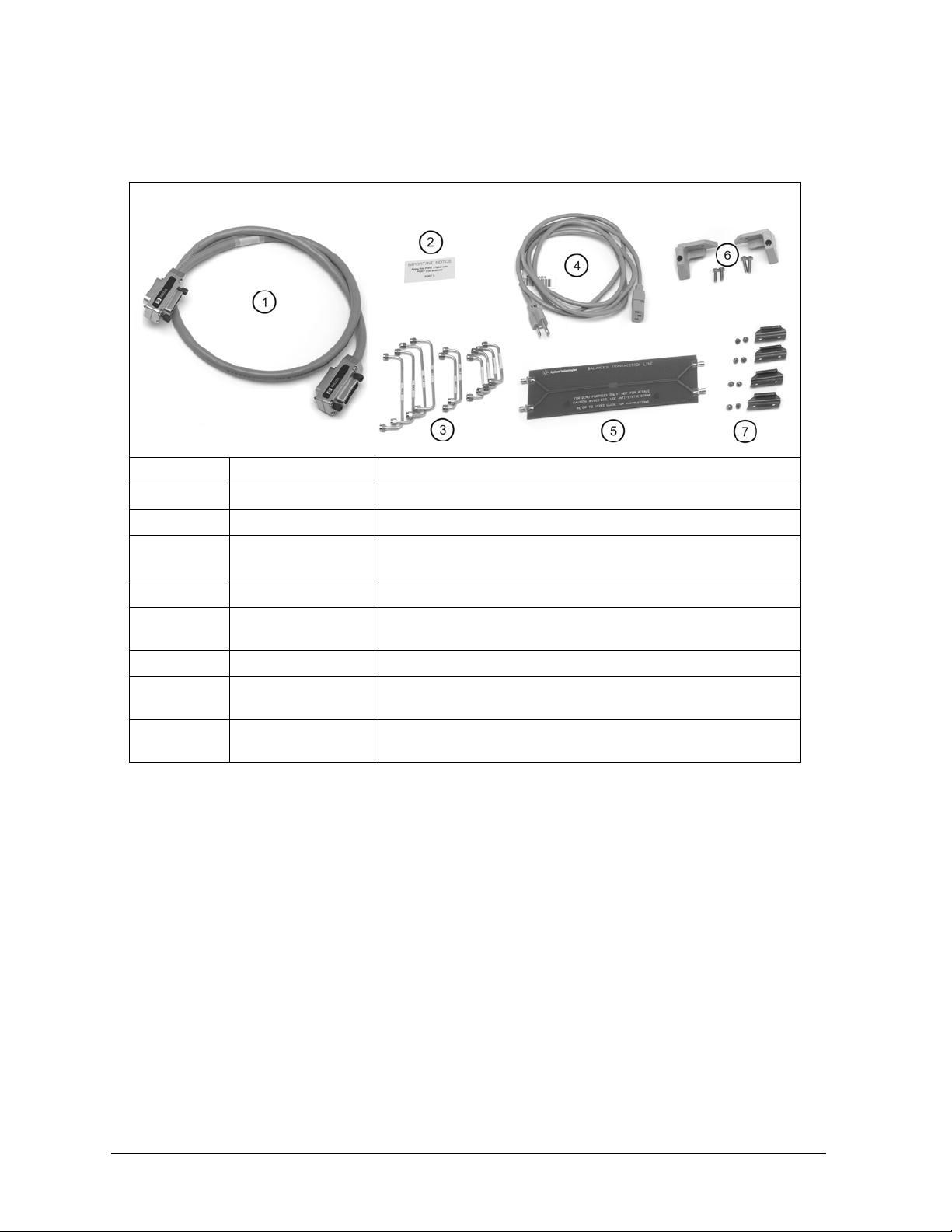
3. Check the accessories that were shipped with your system. Your network analyzer
accessories will be checked during the network analyzer setup.
Item Nr Part Number Part Description
1 8120-3445 GPIB Cable (3 feet)
2 N/A “Port 3” Label
3 Varies by Test Set
Model and Option
Semirigid interconnect cables (refer to Step 5. Make the
Interconnections between the Test Set and the PNA
).
4 Unique to country AC Power Cord (for the test set)
5 AD00658 Balanced Transmission Line PC Board Device (Sample DUT).
Included ONLY when purchased with PLTS system.
6 5023-0132 Rear Locking Feet (for the PNA)
--
(not shown)
7 1600-1423 4 Lock Links (N4420B, N4421B only) with 8 screws
5063-9253 Kit Including Rear Locking Feet (for the Test Set)
(0515-1499)
1-4
Page 11
Installing the Test Set
Step 1. Verify your Shipment
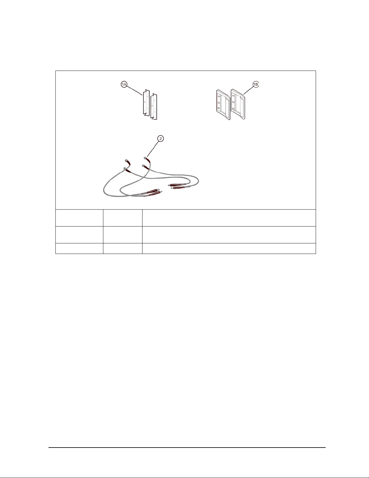
4. If you ordered any of the following options, check the parts. Option 1CP is shipped in
a separate container.
Option
Number
1CP 1A
B20 2 Precision 50-ohm cables (4)
Item
Number
1B
Part Description
Rack mount flange kit (For use with handles)
Handles (set of 2)
1-5
Page 12
Installing the Test Set
Step 2. Set Up the PNA
Step 2. Set Up the PNA
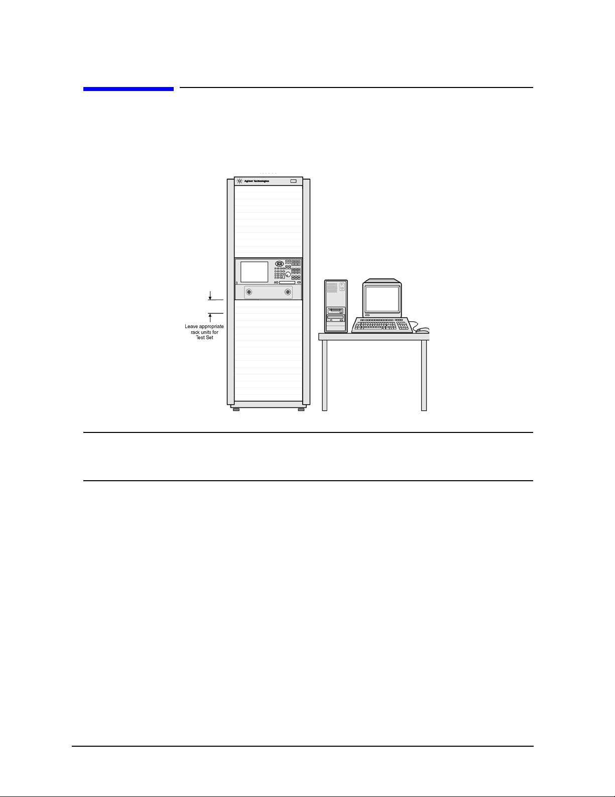
1. Using the PNA Installation and Quick Start Guide, set up the network analyzer.
2. If you are installing your PNA in an equipment rack, be sure to leave at least 2 rack
units of space below the analyzer to install the test set.
NOTE For the N4420B or N4421A/B test set, connect the PNA to the test set
before placing in the rack as a single unit on one set of rails. Refer to“Step
3. Attach the PNA to the Test Set” on page 1-7 for instructions.
1-6
Page 13
Installing the Test Set
Step 3. Attach the PNA to the Test Set
Step 3. Attach the PNA to the Test Set
(N4420B or N4421B Test Set Only)
If your test set is an N4419B, continue with “Step 4. Install the System on a Bench Top
or in an Equipment Rack” on page 1-11.
The PNA is attached to the N4420B and N4421B test sets using lock links at the front
and locking feet at the rear.
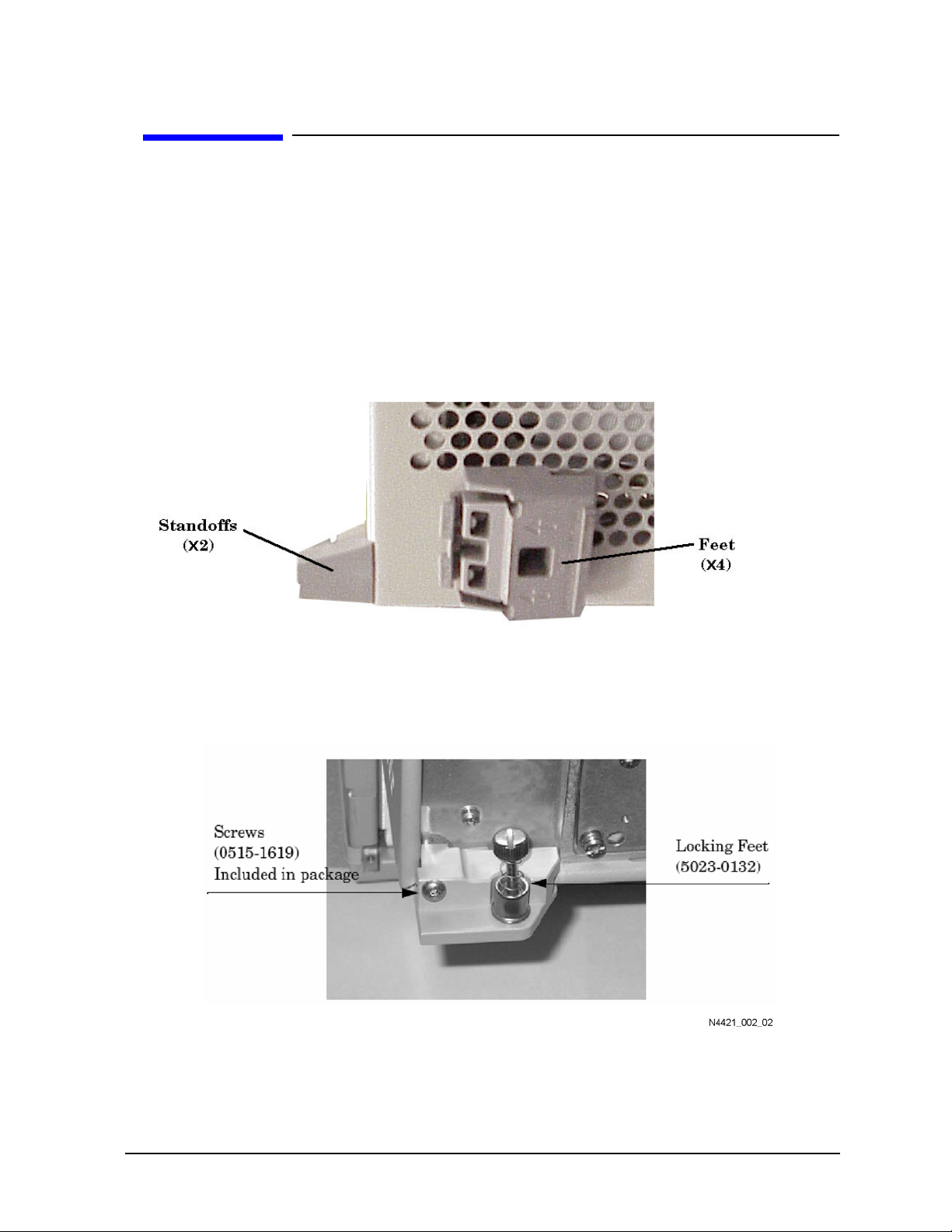
Preparing the PNA
1. Remove the four feet from the bottom of the PNA.
2. Remove the screws from the two lower rear panel standoffs.
3. Install the two rear locking feet (5023-0132) where the standoffs were removed. The
locking feet may require GENTLE tapping with a hammer to seat properly. Use the
screws (part number 0515-1619) that are included to secure the feet to the PNA.
1-7
Page 14
Installing the Test Set
Step 3. Attach the PNA to the Test Set
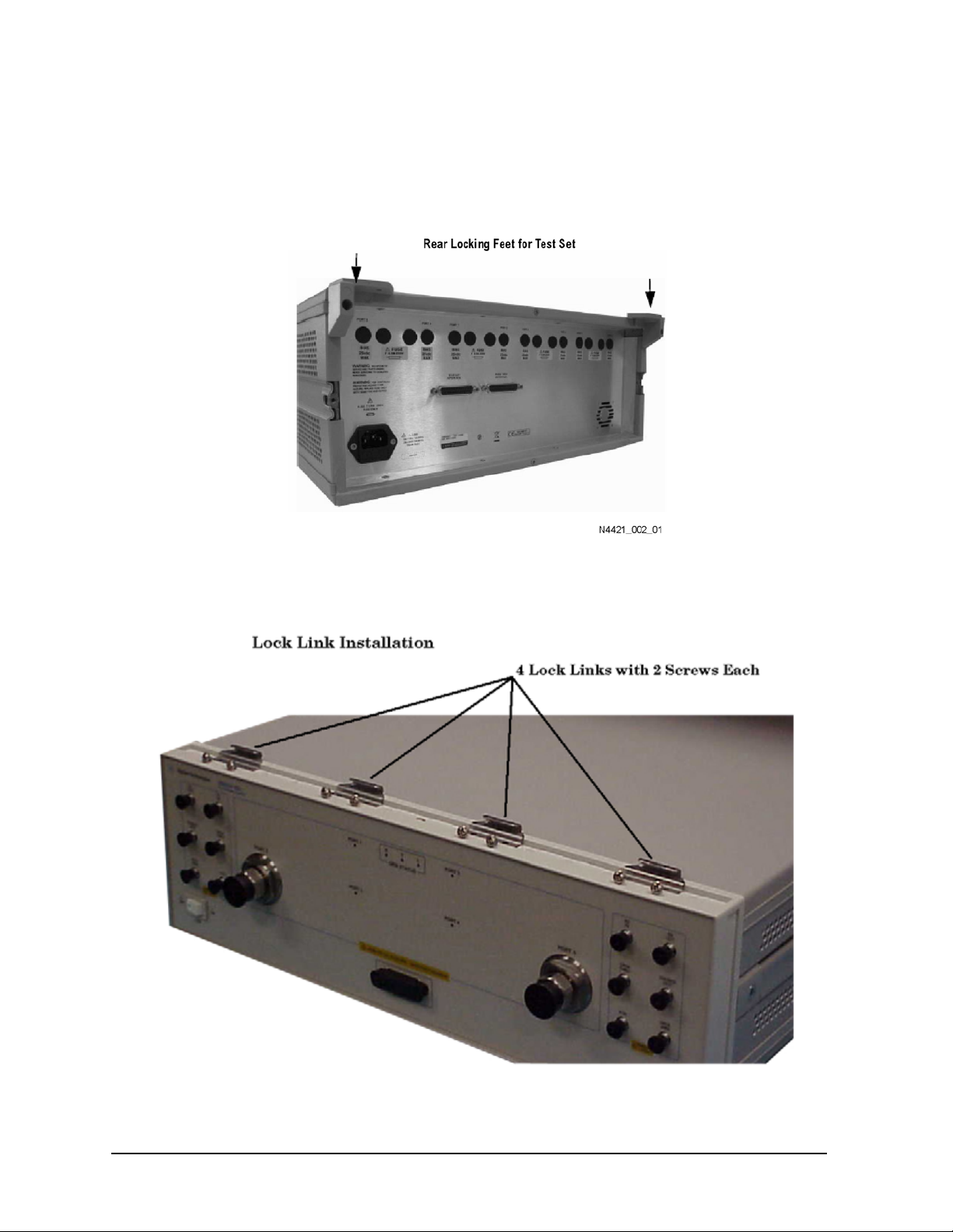
Preparing the Test Set
4. Remove the two standoffs and screws (0515-1619) from the rear panel on the test set.
5. Install the top left and right rear locking feet from the kit (5063-9253) using screws
(0515-1244).
6. Remove the trim strip from the top of the front frame.
7. Install the four lock links from the kit (5063-9253) to the top of the front frame using
eight screws. Refer to the graphic below.
1-8
Page 15

Installing the Test Set
Step 3. Attach the PNA to the Test Set
Attaching the PNA to the Test Set
8. Place the PNA on top of the test set ensuring that the front frame of the PNA is
positioned slightly forward of the lock links that are attached to the the test set. Then
slide the PNA back so the lock links engage the front frame of the analyzer.
1-9
Page 16

Installing the Test Set
Step 3. Attach the PNA to the Test Set
9. Secure the PNA lower locking feet to the test set’s upper locking feet, using the
spring-loaded screws.
NOTE If the screw holes are not aligned, loosen the screws that secure the feet to
both the PNA and the test set to align the screw holes.
10.Tighten all screws.
1-10
Page 17

Installing the Test Set
Step 4. Install the System on a Bench Top or in an Equipment Rack
Step 4. Install the System on a Bench Top or in an
Equipment Rack
The test system can be installed on a bench top or in an equipment rack.
In all installations, consider the following ventilation requirements when deciding
where to set up your test system.
CAUTION Ventilation Requirements:
When installing the product in a cabinet, the convection into and out of the
product must not be restricted. The ambient temperature (outside the
cabinet) must be less than the maximum operating temperature of the
instrument by 4 °C for every 100 watts dissipated in the cabinet. If the total
power dissipated in the cabinet is greater than 800 watts, then forced
convection must be used.
Refer to the section that applies to your installation.
• For bench top installation, continue on page 12.
• For equipment rack installation, continue on page 13.
1-11
Page 18

Installing the Test Set
Step 4. Install the System on a Bench Top or in an Equipment Rack
To Install on a Bench Top
1. Place the test set and PNA on a bench top. In the example illustration shown below,
the system is placed on a riser as an alternative to the bench top. Make sure that
there is at least four inches of clearance on the sides and back of the system for
adequate ventilation.
The front panel test cables are shown only as a reminder to make sure they can easily
reach the test surface of the bench.
CAUTION Consider the ventilation requirement described on page 11 when selecting
the location of your system.
2. Continue with “Step 5. Make the Interconnections between the Test Set and the PNA”
on page 1-17.
1-12
Page 19

Installing the Test Set
Step 4. Install the System on a Bench Top or in an Equipment Rack
To Install in an Equipment Rack
You may install the system in an equipment rack in one of following two ways:
Removing Feet from PNA Leaving Feet attached to PNA
1. Install one set of rails into the
equipment rack
2. Remove feet from Test Set and PNA
3. Attach mount flanges and the handles to
Tes t S et
4. Attach mount flanges and the handles to
PNA
5. Insert test set on rails in equipment rack
and screw to rack
6. Place PNA on top of test set and screw
PNA into rack
7. Bend Semi-rigid interconnect cables to
fit between the test set connector and the
PNA connector
8. Connect semirigid between test set and
PNA
1. Install one set of rails into the
equipment rack
2. Remove feet from Test Set only
3. Attach mount flanges and the handles to
Tes t S e t
4. Attach mount flanges and the handles to
PNA
5. Insert test set on rails in equipment rack
and screw to rack
6. Place PNA on top of test set
7. Connect semirigid between test set and
PNA
When you install the test set in an equipment rack, you will install rails in the rack to
support the weight of the test set, attach the handles and the rack mount flanges to the
test set, and secure the test set to the equipment rack.
1. Ensure that the front handle kit, the rack mount flange kit, and the rack mount rail
set are complete.
Handle Kit Contents Flange Kit Contents
• 4 Screws
• 2 Side Trim Strip
•2 Handles
• Installation Instructions
• 4 Screws (Long)
• 4 Screws with Washers
• 4 Nuts with Metal Clips
•2 Flanges
• Installation Instructions
NOTE If any items are damaged or missing from a kit, contact us to order a
replacement kit. Items within these kits are not individually available.
2. Install the rails into the equipment rack using the instructions provided. Consider
that the test set is two rack units high (3.5 inches). Mount the test set immediately
below the PNA.
NOTE For the N4420B or N4421B test set, connect the network analyzer to the
test set before placing in the rack as a single unit on one set of rails.
3. Attach the cabinet mount flanges and the handles to the sides of the front panel,
1-13
Page 20

Installing the Test Set
Step 4. Install the System on a Bench Top or in an Equipment Rack
using two long screws per side. (Attach the flanges to the outside of the handles.)
WARNING If an instrument handle is damaged, you should replace it
immediately. Damaged handles can break while you are moving or
lifting the instrument and cause personal injury or damage to the
instrument.
1-14
Page 21

Installing the Test Set
Step 4. Install the System on a Bench Top or in an Equipment Rack
4. Remove the feet before cabinet mounting the analyzer using the directions imprinted
on the feet.
5. Ensure there is adequate clearance between the system cabinet and the sides and
back of the test system for adequate ventilation.
CAUTION Consider the ventilation requirements described in “Step 4. Install the
System on a Bench Top or in an Equipment Rack” on page 11 when
selecting the location of your system.
1-15
Page 22

Installing the Test Set
Step 4. Install the System on a Bench Top or in an Equipment Rack
6. Lift the test set and slide it onto the rails that you installed earlier from the front of
the equipment rack. Secure the test set to the equipment rack using the screws with
washers and metal-clipped nuts provided in the flange kit.
7. Continue with “Step 5. Make the Interconnections between the Test Set and the PNA”
on page 17.
1-16
Page 23

Installing the Test Set
Step 5. Make the Interconnections between the Test Set and the PNA
Step 5. Make the Interconnections between the Test Set
and the PNA
1. Locate your test set and PNA model on the following pages for information describing
the interconnections between the test set and the network analyzer.
2. Connect the provided interconnect cables between the test set and the PNA. Torque
the semirigid cable connectors to 8 inch-pounds.
NOTE The Reference channel path through the test set is used to compensate for
electrically long DUTs. This also results in added loss in the Reference
channel and higher trace noise.
Therefore, do NOT use the Reference channel interconnect cables unless
making high speed measurements of electrically long devices.
For more information, see ‘Electrically long devices’ in the PNA Help
system.
CAUTION Be careful to install the interconnect cables correctly. The longer end of the
interconnect cable connects to the PNA front panel connector as shown
in the following image.
Figure 1-1 Interconnect Cable Orientation
1-17
Page 24

Installing the Test Set
Step 5. Make the Interconnections between the Test Set and the PNA
Damage to the interconnect cable can result from improper connection of
the cable.
TIP If the test set and the PNA are rack mounted, the screws securing the rack
mount flanges to the instrument rack may be loosened slightly to allow for
minor repositioning of the instruments. Don't forget to retighten the screws
when you are done.
3. Continue with “Step 6. Set Up the General Purpose Interface Bus (GPIB)” on
page 1-23.
1-18
Page 25

Step 5. Make the Interconnections between the Test Set and the PNA
N4420B Test Set with E8363B and N4421B Test Set with E8364B
Installing the Test Set
CAUTION Damage to the interconnect cable can result from improper orientation of
the cable. Refer to page 1-16 for detailed information regarding the correct
cable orientation.
1-19
Page 26

Installing the Test Set
Step 5. Make the Interconnections between the Test Set and the PNA
Call Out
Sequence
1* Z5623-20215 REF 1 SOURCE OUT REF 1 R1 OUT
2* Z5623-20215 REF 1 RCVR R1 IN REF 1 RCVR R1 IN
3* Z5623-20215 REF 2 RCVR R2 IN REF 2 RCVR R2 IN
4* Z5623-20215 REF 2 SOURCE OUT REF 2 R2 OUT
5 Z5623-20216 PORT 1 SOURCE OUT PORT 1 SOURCE OUT
6 Z5623-20216 PORT 1 CPLR THRU PORT 1 CPLR THRU
7 Z5623-20216 PORT 2 CPLR THRU PORT 2 CPLR THRU
8 Z5623-20216 PORT 2 SOURCE OUT PORT 2 SOURCE OUT
9 Z5623-20217 PORT 1 CPLR ARM PORT 1 CPLR ARM
10 Z5623-20217 PORT 1 RCVR A IN PORT 1 RCVR A IN
11 Z5623-20217 PORT 2 RCVR B IN PORT 2 RCVR B IN
12 Z5623-20217 PORT 2 CPLR ARM PORT 2 CPLR ARM
13* E8364-20059 REF 1 on rear panel of the test set
14* E8364-20059 REF 2 on rear panel of the test set
Cable Part
Number
From
Network Analyzer
To
Test S e t
NOTE * The Reference channel path through the test set is used to compensate for
electrically long DUTs. This also results in added loss in the Reference
channel and higher trace noise.
Therefore, unless making high speed measurements of electrically long
devices, do NOT remove the PNA REFERENCE 1 and REFERENCE 2
front-panel loops, and do NOT use the Reference channel interconnect
cables (items 1, 2, 3, 4, 13, and 14).
For more information, see ‘Electrically long devices’ in the PNA Help
system.
1-20
Page 27

Step 5. Make the Interconnections between the Test Set and the PNA
N4419B Test Set with E8362B or N5230A Option 225
Installing the Test Set
CAUTION Damage to the interconnect cable can result from improper orientation of
the cable. Refer to page 1-16 for detailed information regarding the correct
cable orientation.
1-21
Page 28

Installing the Test Set
Step 5. Make the Interconnections between the Test Set and the PNA
NOTE: Cables are orderable only as cable set AD00756.
Call Out
Sequence
1* AD00756-1 REF 1 SOURCE OUT REF 1 SOURCE OUT
2* AD00756-1 REF 1 RCVR R1 IN REF 1 RCVR R1 IN
3* AD00756-1 REF 2 RCVR R2 IN REF 2 RCVR R2 IN
4* AD00756-1 REF 2 SOURCE OUT REF 2 SOURCE OUT
5 AD00756-2 PORT 1 SOURCE OUT PORT 1 SOURCE OUT
6 AD00756-2 PORT 1 CPLR THRU PORT 1 CPLR THRU
7 AD00756-2 PORT 2 CPLR THRU PORT 2 CPLR THRU
8 AD00756-2 PORT 2 SOURCE OUT PORT 2 SOURCE OUT
9 AD00756-3 PORT 1 CPLR ARM PORT 1 CPLR ARM
10 AD00756-3 PORT 1 RCVR A IN PORT 1 RCVR A IN
11 AD00756-3 PORT 2 RCVR B IN PORT 2 RCVR B IN
12 AD00756-3 PORT 2 CPLR ARM PORT 2 CPLR ARM
13* AD00756-4 REF 1 on rear panel of the test set
14* AD00756-4 REF 2 on rear panel of the test set
Cable Part
Number
From
Network Analyzer
To
Test S e t
NOTE * The Reference channel path through the test set is used to compensate for
electrically long DUTs. This also results in added loss in the Reference
channel and higher trace noise.
Therefore, unless making high speed measurements of electrically long
devices, do NOT remove the PNA REFERENCE 1 and REFERENCE 2
front-panel loops, and do NOT use the Reference channel interconnect
cables (items 1, 2, 3, 4, 13, and 14).
For more information, see ‘Electrically long devices’ in the PNA Help
system.
1-22
Page 29

Installing the Test Set
Step 6. Set Up the General Purpose Interface Bus (GPIB)
Step 6. Set Up the General Purpose Interface Bus (GPIB)
The PNA uses the General Purpose Interface Bus (GPIB) to communicate with the test
set.
NOTE There are 31 GPIB addresses, numbered 0 to 30. However, there may be
the occasion that you need to change the GPIB address for test equipment.
GPIB addresses are set either using rear panel switches or using the
equipment firmware. Refer to the PNA or PLTS online help for more
information.
1. Connect a GPIB cable from the rear panel GPIB connector on the PNA to the rear
panel GPIB connector on the test set.
If the PNA has two GPIB ports, connect the test set to the CONTROLLER GPIB port.
1-23
Page 30

Installing the Test Set
Step 7. Power up the System
Step 7. Power up the System
1. Ensure the available ac power supply meets the Power Source Requirements and the
operating environment meets the Operating Environment Requirements listed below.
Power Source Requirements
Input Voltage Range 100 − 120 Vac - or - 220 − 250 Vac
Frequency Range 47 − 62 Hz / 400 Hz
Power 40 VA maximum.
Operating Environment Requirements
Operating Environment Indoor use
Altitude Operating:
Storage:
Tempe r atu r e 0 °C to 40 °C
Maximum Relative Humidity 80% for temperatures up to 31 °C; decreasing
linearly to 50% for a temperature of 40 °C
0 to 2.0 km (6,560 ft.)
0 to 15.24 km (50,000 ft.)
2. Verify that the ac power cable is not damaged, and that the power-source outlet
provides a protective earth contact.
CAUTION Always use the three-prong ac power cord supplied with this product.
Failure to ensure adequate earth grounding by not using this cord may
cause product damage.
3. Turn off the PNA.
4. Connect the ac power cable from the power-source outlet to the ac input on the rear
panel of the test set.
5. Turn on the PNA and the test set by pressing the ON/OFF button on the front panel
of each instrument.
NOTE Perform Step 6 ONLY when both of the following are true. Otherwise, skip
to Step 7.
• Using the Reference channel paths through the test set. See page
1-16 for more information
• Using a PNA model E8362A/B, E8363A/B, or E8364A/B.
6. The Phase-Lock IF Gain Adjustment adjusts the R Channel receivers ALC gain to
ensure phase lock over the entire frequency range. Refer to Phase-Lock IF Gain
Adjustment in the PNA Help system for details.
a. Ensure the PNA is NOT already in 4-port mode (Step 7).
b. On the PNA, from the System menu, click Service, then Adjustments, then IF
1-24
Page 31

Installing the Test Set
Step 7. Power up the System
Gain Adjustment.
c. In Select Specials, select None.
d. No connections to the test ports are required.
e. Click Begin Adj. The adjustment takes about a minute to complete.
The advanced screen is for factory personnel only.
NOTE To start the PNA in 4-port mode (Step 7), Option 550 must already be
enabled on the PNA. See PNA Help to learn more about Option 550.
In addition, the PNA must have firmware version A.06.03.05 or later.
To check both of these on the PNA, click Help, then About Network
Analyzer.
7. When the PNA application has completely powered up, and the default trace is
present, then:
a. Click System, point to Configure, then click Multiport Capability
b. On the Multiport Restart dialog, select Testset: N44xx, then click Restart as a
Multiport PNA with this testset.
c. Click OK
The PNA should shut down and restart as a 4-port PNA. To learn more about the
Option 550 capabilities and limitations, see PNA Help. In the Help file index, type
“Option 550”.
8. If you intend to always use the default port mapping, attach the “Port 3” label
(included with accessories) over the “Port 2” label on the PNA front panel. This will
help to eliminate confusion when referring to the system “logical” ports. To learn
more about port mapping, see the PNA Help, option 550 topic.
1-25
Page 32

Installing the Test Set
Step 8. Perform Quick Check
Step 8. Perform Quick Check
This Quick Check procedure helps to ensure that the system is properly configured.
Perform this check after the PNA has rebooted as a 4-port PNA (previous step).
NOTE An Operator’s Check, used to confirm that the 4-port system is fully
functional, is contained in the N4419B, N4420B, N4421B Service Guide.
Download the Service Guide at www.na.tm.agilent.com/multiport
All four test ports should be open and in the default port mapping configuration.
1. Preset the PNA.
2. Set the stop frequency on the PNA channel to the maximum frequency of either the
test set or the PNA, which ever is lower. This is probably the default setting.
3. On the PNA, click Trace, then Delete Trace to delete the S11 trace.
4. On the PNA, click Trace, then New Trace, then check S12, S13, and S14. Click OK.
This creates three new traces in the same channel and window. All of the new traces
should appear at the bottom, or below, the window.
5. Connect a Thru cable between logical ports 1-2, then between ports 1-3, then between
ports 1-4. This assumes that you have NOT changed port mapping. Port 3 is the PNA
“physical” port 2. Port 2 and port 4 is on the test set.
Each trace should look similar to the uncorrected trace in the following figure.
1-26
Page 33

2 Specifications and
Characteristics
2-1
Page 34

Specifications and Characteristics
Definitions
Definitions
All specifications and characteristics apply over a 25 °C ±5 °C range (unless otherwise
stated) and 90 minutes after the instrument has been turned on.
Specification (spec.) Warranted performance. Specifications include guard bands to
account for the expected statistical performance distribution,
measurement uncertainties, and changes in performance due to
environmental conditions.
Characteristic (char.) A performance parameter that the product is expected to meet
before it leaves the factory, but that is not verified in the field
and is not covered by the product warranty. A characteristic
includes the same guard bands as a specification.
Typical (typ.) Expected performance of an average unit which does not
include guard bands. It is not covered by the product warranty.
Nominal (nom.) A general, descriptive term that does not imply a level of
performance. It is not covered by the product warranty.
NOTE There are NO specifications for multiport test set performance; only
Characteristics and Typicals.
The Characteristic and Typical performance information is contained in the
N4419B, N4420B, N4421B Service Guide, which is available at
www.na.tm.agilent.com/multiport
2-2
Page 35

Specifications and Characteristics
General Characteristics
General Characteristics
The frequency range, environmental operating conditions, and physical characteristics
are displayed on the following pages.
Frequency Range
Table 2-1Test Set Frequency Range and PNA Model
Test Set Model Frequency Range Recommended PNA Model
N4419B 10 MHz to 20 GHz E8362B or N5230A Opt 225
N4420B 10 MHz to 40 GHz E8363B or N5230A Opt 425
N4421B 10 MHz to 50 GHz E8364B or N5230A Opt 525
2-3
Page 36

Specifications and Characteristics
General Characteristics
Physical Characteristics
The weight and dimensions for the test sets are listed below.
Weight and Dimensions
Table 2-2Test Set Weight and Dimensions
Model Number Weight Dimensions
Height (A) Width (B) Depth (C)
N4419B 9.0 kilograms
(19.9 pounds)
N4420B and N4421B 9.0 kilograms
(19.9 pounds)
3.0 in
(7.62 cm)
5.5 in
(13.97 cm)
16.75 in
(42.55 cm)
16.75 in
(42.55 cm)
19.25 in
(48.90 cm)
16.75 in
(42.55 cm)
2-4
Page 37

3 Safety and Regulatory
Information
3-1
Page 38

Safety and Regulatory Information
Safety Information
Safety Information
Review to the safety information in this section before operating your physical layer test
system.
Safety Symbols
The following safety symbols are used throughout this manual. Familiarize yourself
with each of the symbols and its meaning before operating the physical layer test
system.
CAUTION Caution denotes a hazard. It calls attention to a procedure that, if not
correctly performed or adhered to, would result in damage to or destruction
of the instrument. Do not proceed beyond a caution note until the indicated
conditions are fully understood and met.
WARNING Warning denotes a hazard. It calls attention to a procedure which,
if not correctly performed or adhered to, could result in injury or
loss of life. Do not proceed beyond a warning note until the
indicated conditions are fully understood and met.
3-2
Page 39

Safety and Regulatory Information
Safety Information
Instrument Markings
Familiarize yourself with each of the markings and its meaning before operating the
physical layer test system.
The instruction documentation symbol. The product is marked with this symbol
when it is necessary for the user to refer to the instructions in the documentation.
This symbol indicates that the instrument requires alternating current (ac) input.
This symbol indicates separate collection for electrical and electronic equipment,
mandated under EU law as of August 13, 2005. All electric and electronic equipment
are required to be separated from normal waste for disposal (Reference WEEE
Directive, 2002/96/EC).
This symbol indicates that the power line switch is ON.
This symbol indicates that the power line switch is in the STANDBY position.
This symbol indicates that the power line switch is in the OFF position.
ICES/NMB-001
This symbol is used to identify a terminal which is internally connected to the
product frame or chassis.
The CE mark is a registered trademark of the European Community. (If
accompanied by a year, it is when the design was proven.)
The CSA mark is a registered trademark of the CSA International. This instrument
complies with Canada: CSA 22.2 No. 61010-1-04.
This is a symbol of an Industrial Scientific and Medical Group 1 Class A product.
This is a marking to indicate product compliance with the Canadian
Interference-Causing Equipment Standard (ICES-001).
Direct Current.
This is a required mark signifying compliance with an EMC requirement. The C-Tick
mark is a registered trademark of the Australian Spectrum Management Agency.
China RoHS regulations include requirements related to packaging, and require
compliance to China standard GB18455-2001.
This symbol indicates compliance with the China RoHS regulations for
paper/fiberboard packaging.
3-3
Page 40

Safety and Regulatory Information
Safety Information
Safety Considerations
Familiarize yourself with each of the safety considerations before operating the physical
layer test system.
NOTE Positioning the Test System for Use
When setting up the test set for use, position the equipment so that the
front panel power switch is easy to reach.
NOTE This instrument has been designed and tested in accordance with the
standards listed on the Manufacturer’s Declaration of Conformity and has
been supplied in a safe condition. This instruction documentation contains
information and warnings which must be followed by the user to ensure
safe operation and to maintain the instrument in a safe condition.
Safety Earth Ground
WARNING This is a Safety Class 1 product (provided with a protective
earthing ground incorporated in the power cord). The mains plug
shall only be inserted in a socket outlet provided with a protective
earth contact. Any interruption of the protective conductor, inside
or outside the instrument, is likely to make the instrument
dangerous. Intentional interruption is prohibited.
CAUTION Always use the three-prong AC power cord supplied with this product.
Failure to ensure adequate earth grounding by not using this cord may
cause product damage.
3-4
Page 41

Safety and Regulatory Information
Safety Information
Before Applying Power
CAUTION Install the instrument so that the ON/OFF switch is readily identifiable
and is easily reached by the operator. The ON/OFF switch or the detachable
power cord is the instrument disconnecting device. It disconnects the mains
circuits from the mains supply before other parts of the instrument.
Alternately, an externally installed switch or circuit breaker (which is
readily identifiable and is easily reached by the operator) may be used as a
disconnecting device.
CAUTION Before switching on this instrument, make sure that the correct fuse is
installed and the supply voltage is in the specified range.
Servicing
WARNING No operator serviceable parts inside. Refer servicing to qualified
personnel. To prevent electrical shock, do not remove covers.
WARNING These servicing instructions are for use by qualified personnel
only. To avoid electrical shock, do not perform any servicing unless
you are qualified to do so.
WARNING The opening of covers or removal of parts is likely to expose
dangerous voltages. Disconnect the instrument from all voltage
sources while it is being opened.
WARNING The power cord is connected to internal capacitors that may
remain live for 5 seconds after disconnecting the plug from its
power supply.
WARNING For continued protection against fire hazard replace line fuse only
with same type and rating (115V and 230V operation: T2.5A 250V).
The use of other fuses or material is prohibited.
3-5
Page 42

Safety and Regulatory Information
Safety Information
General
WARNING To prevent electrical shock, disconnect the Agilent Technologies
(N4419B, N4420B, and N4421B) S-parameter test set from mains
before cleaning. Use a dry cloth or one slightly dampened with
water to clean the external case parts. Do not attempt to clean
internally.
WARNING If this product is not used as specified, the protection provided by
the equipment could be impaired. This product must be used in a
normal condition (in which all means for protection are intact)
only.
CAUTION This product is designed for use in Installation Category II and Pollution
Degree 2.
CAUTION VENTILATION REQUIREMENTS: When installing the product in a
cabinet, the convection into and out of the product must not be restricted.
The ambient temperature (outside the cabinet) must be less than the
maximum operating temperature of the product by 4° C for every 100 watts
dissipated in the cabinet. If the total power dissipated in the cabinet is
greater that 800 watts, then forced convection must be used.
3-6
Page 43

Safety and Regulatory Information
Regulatory Information
Regulatory Information
The Agilent Technologies S-Parameter test set complies with the regulatory
requirements listed in this section.
EMC
Complies with European EMC Directive 2004/108/EC.
• IEC/EN 61326-2-1
• CISPR Pub 11 Group 1, class A
• AS/NZS CISPR 11
SAFETY
Complies with European Low Voltage Directive 2006/95/EC.
• IEC/EN 61010-1, 2nd edition
• Canada: CSA C22.2 No. 61010-01-04
• USA: UL std no 61010-1, 2nd edition
Compliance with Canadian EMC Requirements
This ISM device complies with Canadian ICES-001.
Cet appareil ISM est conforme a la norme NMB du Canada.
Compliance with German Noise Requirements
This is to declare that this instrument is in conformance with the German Regulation on
Noise Declaration for Machines (Laermangabe nach der Maschinenlaermrerordung −3.
GSGV Deutschland).
Acoustic Noise Emission/Geraeuschemission
LpA <70 dB LpA <70 dB
Operator position am Arbeitsplatz
Normal position normaler Betrieb
per ISO 7779 nach DIN 45635 t. 19
Declaration of Conformity
A copy of the Declaration of Conformity is available upon request, or a copy is available
on the Agilent Technologies web site at
http://regulations.corporate.agilent.com/DoC/search.htm.
3-7
Page 44

Safety and Regulatory Information
Regulatory Information
3-8
 Loading...