

Page 1

HP 3565S
Measurement
Hardware
Technical Specifications
H
Modular hardware for
precision measurements
The HP 3565S measurement
hardware combined with application software and a host computer
forms a high performance multichannel measurement system.
The hardware acquires signals in
both time and frequency domains
and is easily configured for large
multiple input, multiple output
measurements.
System characteristics include:
• Signal acquisition and processing up to 102.4 kHz
• Host-independent—interfaces to
any computer that supports the
IEEE-488 interface.
•Up to 496 input channels
• 102.4 kHz realtime bandwidth
• Display updates of 64 spectra/sec
•Throughput to disk rate of
2.6 Mbytes/sec via SCSI interface
•Buffered analog output for tape
recorders
• Built-in preamps for piezoelectric and integrated electronics
piezo electric transducers
System performance depends
on the application software
used to control the hardware.
Specifications in this data sheet
denote guaranteed performance
of the hardware when controlled
by appropriate software.
System description
The HP 3565S measurement
hardware includes either a single,
4-slot, HP 35650B mainframe or
from 1 to 8 interconnected
HP 35650A mainframes. Each
HP 35650A mainframe contains
8 module slots for a possible
system total of 64 slots. Nine
different of modules can used to
build a system:
• Signal processing module
• 51.2 kHz input module
• 102.4 kHz input module
• 4-channel 12.8 kHz input module
• 8-channel 12.8 kHz input module
• 102.4 kHz source module
• Programmable DAC module
• Tachometer/Trigger module
•SCSI throughput module
Each system must contain one
signal processing module. The
remaining slots may contain
a combination of the other
modules. Module configuration
requirements depend on
application software.
NOTE: Internal calibration of the
hardware requires either a 102.4 kHz
source module or a programmable
DAC module.
NOTE: HP 35635R software supports
multiple synchronized systems
controlled by one host computer.
(The HP 35635R Programmer Toolkit
software is described on page 23.)
A high-speed system bus
provides communication between
mainframes and modules. Data
transfer between the host computer and the signal processing
module takes place via an HP-IB
(IEEE-488) interface.
Page 2
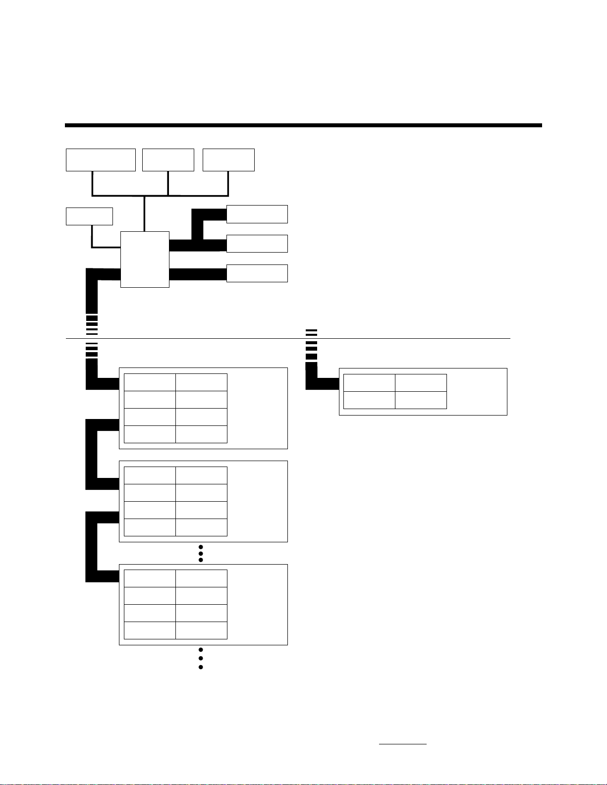
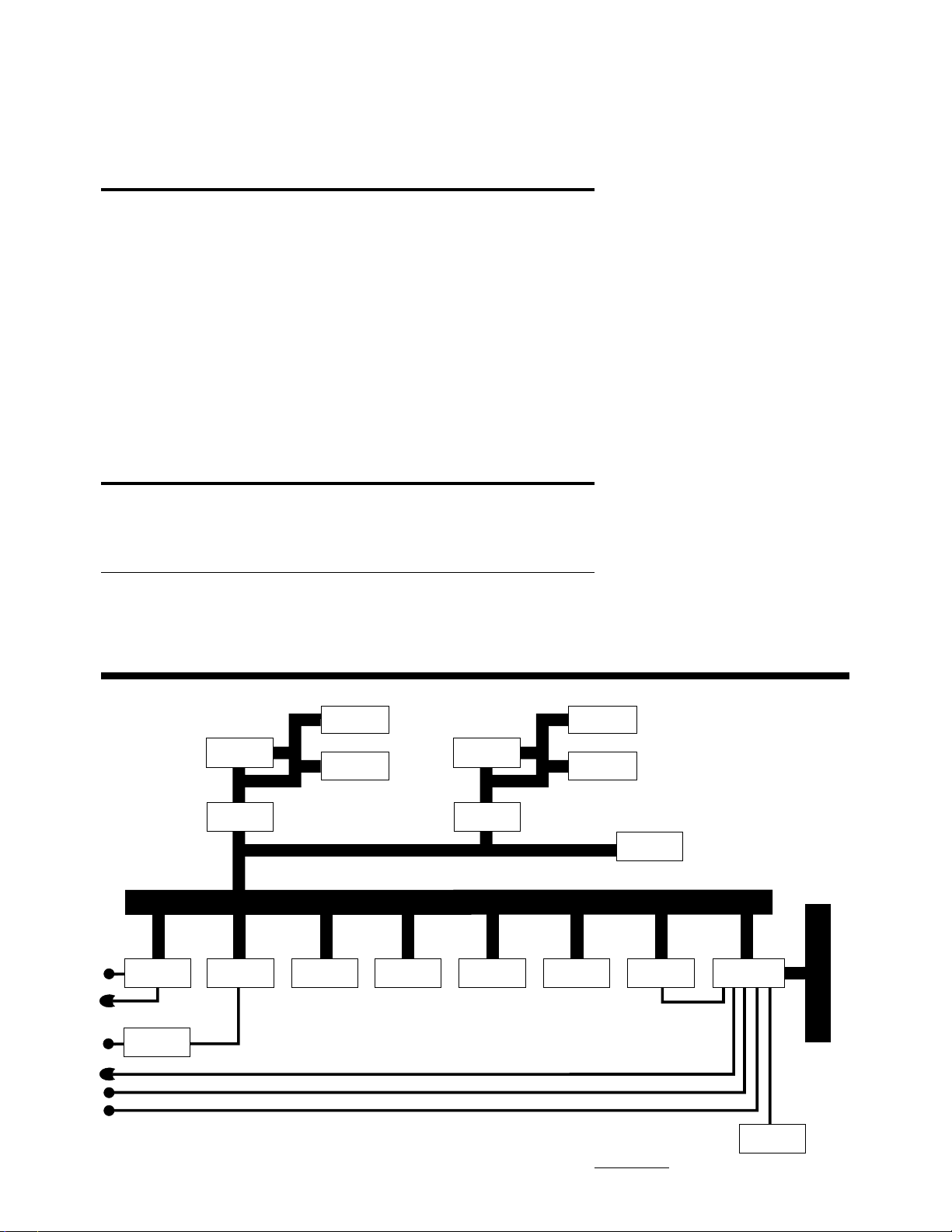
HP 35650A/B Mainframe Systems
Security Module
(optional)
Display
HP 35650A
HP-IB
Mouse
Host
Computer
DSP Module
Module
Module
Module
HP-IB
HP-IB
Module
Module
Module
Module
Keyboard
System Disk
HP 35650A
#1 Mainframe
Plotter
Printer
HP-IB
HP 35650B
Module Module
ModuleDSP Module
HP 35650B
Mainframe
System Bus
System Bus
ModuleModule
Module
Module
Module
Module Module
Module Module
Module Module
Module
Module
Module
ModuleModule
HP 35650A
#2 Mainframe
HP 35650A
#N Mainframe
Maximum
of eight
mainframes
2
Page 3

HP 35650A and 35650B Mainframes
The HP 35650A and 35650B
mainframes house the HP 3565S
modules and provide the following features:
HP35650A HP35650B
Module slots 8 4
Module power yes yes
Forced air yes yes
available
Calibration bus yes yes
Internal sample yes yes
clock
Trigger signal yes yes
System bus yes no*
available for
interconnecting
mainframes
400-Hz line no yes
power
compatible
Two minute fan no yes
cut-off for quiet
operation
Split backplane no yes**
allows 2 signal
processor modules
* A HP 35650B mainframe can not be inter-
connected with other mainframes. It is
strictly limited to operating in single
mainframe systems.
Battery power is available via
the HP 85901A portable AC
power source.
Select the HP 35650A mainframe
when your application requires
more that 4 modules, or to
expand the system later.
The HP 35650A mainframe can
be used on the bench or installed
in either the HP E3660A rack (for
up to two mainframes) or the
HP E3661A rack (for up to four
mainframes). A “top extractor
fan” and appropriate power
distribution units must be ordered. See table on this page.
The HP 35650B mainframe can
also be used on a bench orinstalled in any HP 46298 series rack.
The HP 46298 series rack is
recommended to house rackmountable breakout boxes for
the HP 35655A input modules.
An HP 46298C 1600 mm rack can
hold up to 16-rack panels (equivalent to 256 channels).
System Rack Cabinets
HP E3660A ( 2 Mainframes)
North American
120V order option AW3 PDU
order HP E4470A extractor fan
240V order HP E4472A installation kit
order HP E4452A PDU
International
240V order option AW5 PDU
order HP E4471A extractor fan
HP E3661A (4 Mainframes)
North American
120V order option AW3 PDU
order HP E4455A, second PDU
order HP E4470A extractor fan
240V order HP E4472A PDU installation kit
order HP E4456A PDU (up to 4 mainframes)
order HP E4471A extractor fan
International
240V order option AW5 PDU
order HP E4471A extractor fan
** A HP 35650B can hold two signal processor
modules acting as independent systems.
Order HP 35650B-H01. This configuration
requires user-generated control code.
Select the HP 35650B mainframe
when your application requires
4 modules or less. A signal
processor module, a source, and
2 eight-channel, 12.8 KHz modules
is a typical 4-slot configuration.
Its size and weight also make it a
good solution for applications
requiring transportability.
Specifications
Weight
HP 35650A: 15.3 Kg (33.7 lb)
HP 35650B: 10.9 Kg (24.0 lb)
HP 35651C: 1.6 Kg (3.5 lb)
HP 35652A: 2.0 Kg (4.4 lb)
HP 35652B: 2.0 Kg (4.4 lb)
HP 35653C: 1.6 Kg (3.5 lb)
HP 35654B: 1.6 Kg (3.5 lb)
HP 35655A: 2.0 Kg (4.4 lb)
HP 35655B: 2.0 Kg (4.4 lb)
HP 35656B: 2.0 Kg (4.4 lb)
HP 35658A: 1.5 Kg (3.2 lb)
HP 35659A: 2.4 Kg (5.2 lb) incl.
opt. AT3
3
Page 4

Using Application Software with the HP 3565S
Application software may interact
with the HP 3565S hardware in a
variety of ways. One method is to
access the measurement hardware through an established user
interface such as the HP 3566A
and 3567A PC-based Spectrum/
Network Analyzer software.
Another method is to work with
command libraries available
through the HP 35635R Programmers Toolkit. This method
increases measurement speed
and allows highly customized
measurements. It also requires
significant programming effort on
the part of the user.
The table below shows compatibility between HP 3565S hardware and various application
software products. For information on hardware compatibility
with application software available from third party vendors
contact your Hewlett-Packard
sales representative.
Third Party Support of
HP 3565S Hardware
Various independent third party
software vendors support the
HP 3565S hardware set in their
applications. Each of these
vendors support a different set
of HP 3565S modules to solve
specific user problems and needs.
Applications supporting HP 3565S
hardware are currently provided
by Leuven Measurement Systems
(LMS), Mahrenholtz and Partner
M&P), Structural Measurements
Systems (SMS), Creare Inc.,
Structural Dynamics Research
Corporation (SDRC), and other
local third parties. Specific
HP 3565S hardware support
questions should be addressed
directly to each third party. Your
HP sales representative can give
you more information on these
packages and how to contact
each vendor.
HP 3565S HP VISTA* HP VISTA* HP Prog. Toolkit HP 3566/67A
Modules HP 35630A HP 35630B HP 35635R PC System
HP 35651A X
HP 35651B/C X X X
HP 35652A X X X X
HP 35652B X** X X
HP 35653C X X X X
HP 35654A/B X X X
HP 35655A X X X
HP 35655B X
HP 35656B X X
HP 35658A X X
HP 35659A X X
*Software no longer available for sale
**up to 51.2 kHz only
4
Page 5
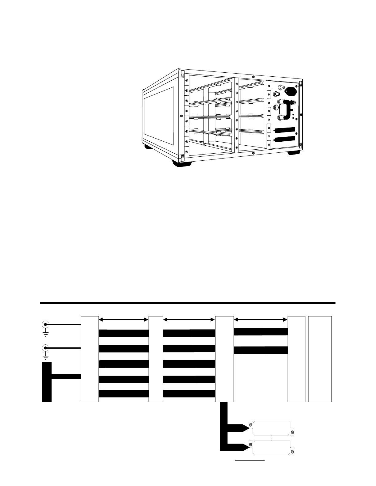
HP 35650A Mainframe
Internal Sample Clock
Generator
Frequency: 262,144 Hz
Accuracy: ±8 ppm
External Sampling Rate
Maximum: 280 kHz
Signal type: TTL
Power Supply
Line Voltage:
115 Vac range: 90 to 127 Vac
230 Vac range: 195 to 253 Vac
Line Frequency: 47.5 to 66 Hz
(either range)
Line Current:
115 Vac range: < 6.0 amps
230 Vac range: < 3.0 amps
Line Power: 600 VA max
Option 715: 15 inch fast bus cable
Option 788: 88 inch, fast bus cable
Rack mount brackets: HP part
number 5062-3979
Mainframe Dimensions
222 mm(8.75 in) high
432 mm(17.0 in) wide
584 mm(23.0 in) deep
Environmental*
Ambient Temp: 0 to 55°C
Altitude: up to 4572 meters
(15,000 feet)
* Environmental specifications for the
mainframe apply to the modules.
NOTE: Two BNC cables and a
system bus cable are required to link
two or more HP 35650A mainframes.
The system bus cable allows all
mainframes and modules to access
common commands and data.
HP 35650A Mainframe
Analog CA L BNCs
Sample Clock
System Bus
Rear
Panel
Configuration Status
Cal Cal Clock
Clocks Clocks
Address Bus Module Address
Data Bus
Control Bus Data Bus
Relative Humidity: Can be
operated in environments with
relative humidity of 95% at 40°C.
Modules should be protected
from rapid temperature changes,
which may cause condensation.
I/O
Module Address Cntrl
Control
Mother
Board
Control
+5 ±18 +28 -2 volts
Power
Supply
Power
Supply
Controller
System Bus
Module Slot 0
through
Module Slot 7
5
Page 6
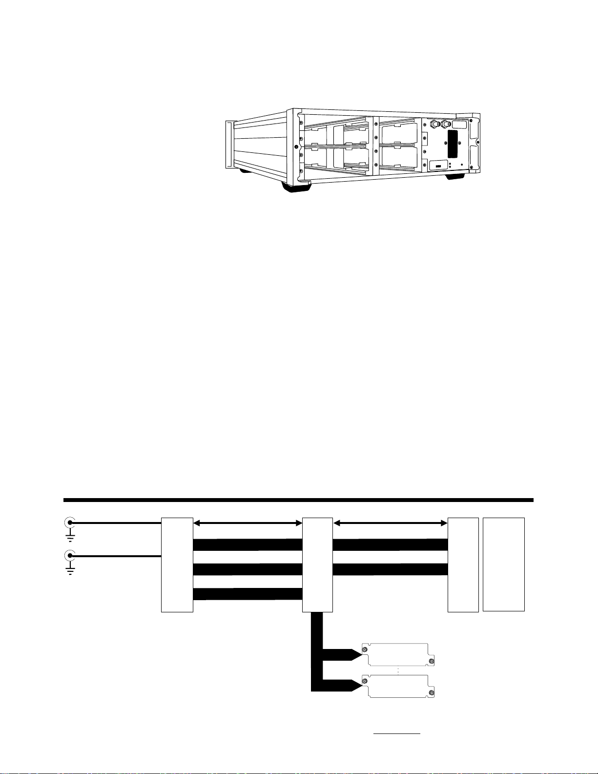
HP 35650B Mainframe
Internal Sample Clock
Generator
Frequency: 262,144 Hz
Accuracy: ±8 ppm
External Sampling Rate
Maximum: 280 kHz
Signal type: TTL
Power Supply
Line Voltage:
115 Vac range: 90 to 127 Vac
230 Vac range: 195 to 253 Vac
Line Frequency:
115 Vac range: 47.5 to 440 Hz
230 Vac range: 47.5 to 66 Hz
Line Current:
115 Vac range: < 3.0 amps
230 Vac range: < 2.0 amps
Line Power: 250 VA max
NOTE: Battery power available via
the HP 85901A Portable AC Power
Source.
Mainframe Dimensions
133 mm(5.25 in) high
432 mm(17.0 in) wide
622 mm(24.5 in) deep
Environmental*
Ambient Temp: 0 to 55°C
Relative Humidity: Can be
operated in environments with
relative humidity of 95% at 40°C.
Modules should be protected
from rapid temperature changes,
which may cause condensation.
Altitude: up to 4572 meters
(15,000 feet)
* Environmental specifications for the
mainframe apply to the modules.
HP 35650B Mainframe
Analog Cal BNCs Cal Clock
Sample Clock
Rear
Panel
Clocks Control
Address Bus +5 ±18 +28 -2 volts
Configuration Status
Mother
Board
System Bus
Power
Supply
Module Slot 0
through
Module Slot 3
Power
Supply
Controller
6
Page 7
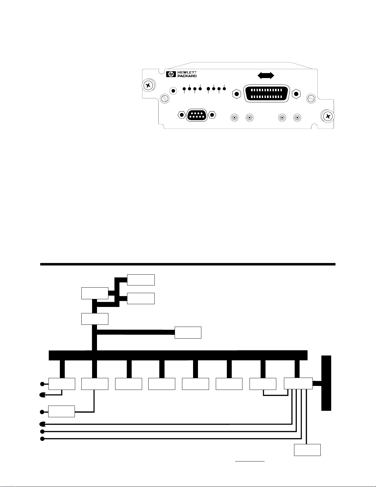
HP 35651C/35654B Signal Processing Modules
The signal processing module
performs the following functions
for the HP 3565S system:
• Control of all system operations,
including data flow between
modules
• Transfer of measurement data to
host computer via HP-IB
•Direct control of data throughput to disk
•Execution of downloadable
programs from application
software
• Syncronization of multiple
systems and simultaneous
triggering of multiple systems
with external SMB connectors.
• System hardware diagnostics
using the RS-232 port.
35651C
INTERFACE / SIGNAL PROCESSOR
RESET
MSRQ TRG LSN SRQ
MIRQ SHUT
SERIAL PORT
RMT TLK
SYSTEM SYNC SYSTEM TRIG
While the HP 35651C and
HP 35654B perform identical
functions, there are two major
differences between the modules.
The HP 35651C has one Motorola
56002 digital signal processing
(DSP) chip and 1 Mbyte of RAM
(4 or 16 Mbytes of RAM are
available by ordering option 104
or 116). The HP 35654B has two
HP-IB
Motorola 56002 DSP chips and
4 Mbytes of memory (16 Mbytes
are available by ordering option
116). The additional DSP chip
gives the HP 35654B the capability of greater signal processing
speed. This added capability is
only accessible through application software that accesses the
extra DSP chip.
HP 35651C Signal Processing Module
SPO
(56002)
DSP
Interface
HP-IB
Interface
LEDs
Serial
Port
LEDs
System Sync
System Trigger
RS-232
Interface
RAM
256k x 32
(1 Mbyte) (256 kbyte) (20MHz)
SRAM (Y)
64kx24
SRAM (X/P)
64kx24
ROMØ
64k x32
(256 kbyte)
ROM1
64kx32
CPU Bus
FPU
(68881)
CPU
(68020)
Filter
Pass Ctr
System Bus
Interface
System Bus
System
Clock
7
Page 8
Features
HP 35651C HP 35654B
DSP chip* DSP56002 (one) DSP56002 (two)
Processor MC68020 (20 MHz) MC68020 (20 MHz)
Floating Point Coprocessor MC68881 MC68882
MC68882 (w/opt 104 or 116)
DSP RAM Wait states 0 0
FFT time (nominal)** 4.0 ms 3.5 ms
Realtime Bandwidth 51.2 kHz 102.4 kHz
Main Memory 1 Mbyte (standard) 4 Mbytes (standard)
4 Mbyte w/opt 104 16 Mbyte w/opt 116
16 Mbyte w/opt 116
* The DSP chip, the processor and the coprocessor are all Motorola products.
** The FFT time is calculated using a 1K complex block size (800 lines of alias-free resolution,
includes windowing, and bit reverse).
Transfer Rates
Module to module system bus maximum: 2.5 Msamples/sec
Signal processing module to host : 329 kbytes/sec
Module to signal processing module memory: 1.7 Msamples/sec
Maximum throughput rate: >1.3 Msamples/sec using HP 35659A with
HP-IB Implementation SH1 AH1 T6 TE0 L4 LE0 SR1 RL0 PP0 DC1 DT1 C4,11
(IEEE Std 488-1978)
option AT3
HP 35654B Signal Processing Module
SPO
(56002)
DSP
Interface
HP-IB
Interface
LEDs
Serial
Port
LEDs
System Sync
System Trigger
RS-232
Interface
RAM
256k x 32
(4 Mbyte) (256kbyte) (20 MHz)
SRAM (Y)
64kx24
SRAM (X/P)
64kx24
ROMØ
64k x32
Interface
CPU Bus
SPO
(56002)
DSP
FPU
(68881)
SRAM (Y)
64kx24
SRAM (X/P)
64kx24
CPU
(68020)
(256 kbyte)
ROM1
64kx32
Filter
Pass Ctr
System Bus
Interface
System Bus
System
Clock
8
Page 9
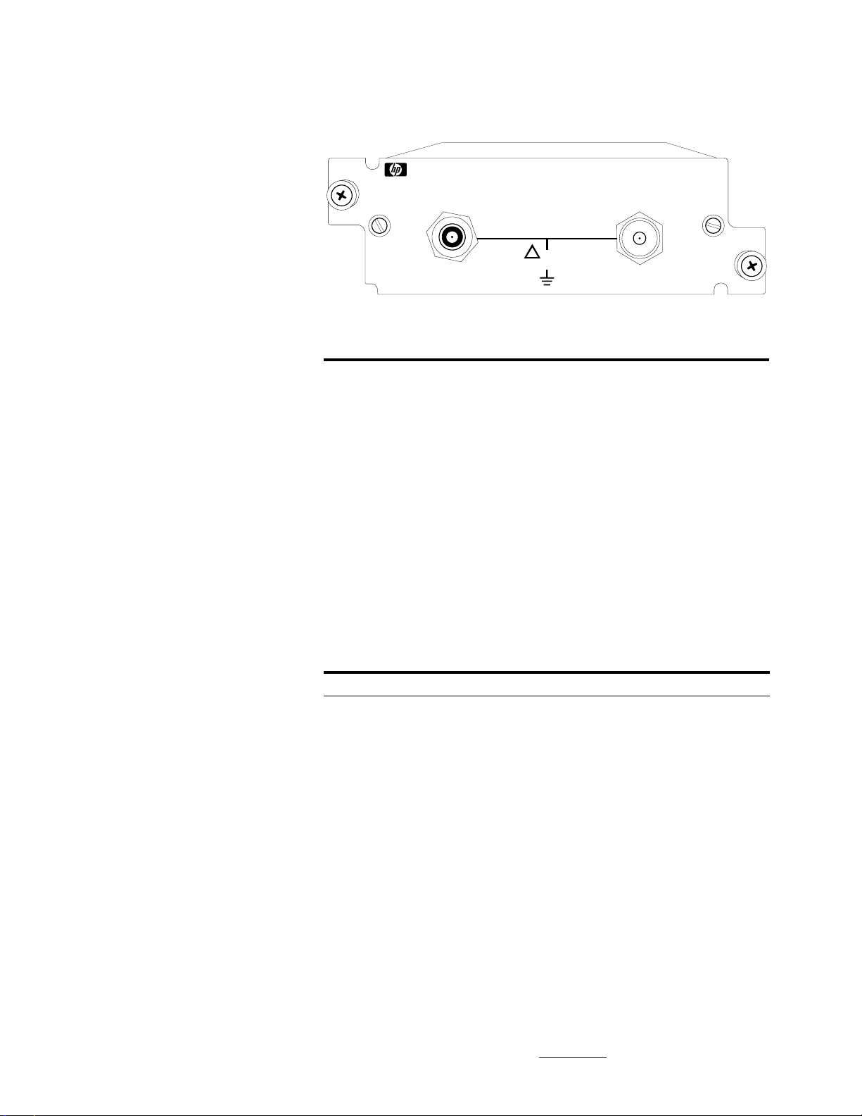
HP 35652A/B Input Modules
The HP 35652A is a single-channel
analog input module for measurements from dc to 51.2 kHz. The
HP 35652B is the same module
with an extended frequency range
up 102.4 kHz. Aside from maximum frequency span, the two
modules have the same features.
The HP 3565S measurement hardware can acquire data from the
HP 35652A/B input modules at an
internal sample rate of 262,144 Hz
per channel. Additional features
include:
• Three input modes: voltage,
charge and IEPE 4 mA
constant-current
• Anti-alias protection on
all spans
• Auto-ranging
• Digital zoom capability on all
spans and all ranges
• 80 dB dynamic range*
•Input data may be transferred
directly to HP 35659A SCSI
interface with optional AT3
disk drive.
• Full scale voltage ranges
from 1.26 mVpk to 39.8 Vpk
in 2 dB steps
• Full scale charge ranges
from 0.126 pC to 3980 pC
in 2 dB steps
* The HP 35652B has 80 dB of dynamic
range at frequencies below 50 kHz.
From 50 kHz to 100 kHz dynamic
range is 75 dB.
35652B 102.4 kHz INPUT MODULE
HE W L E T T • P ACKARD
VOL TAGE/ICPINPUT
!
FLOA T
±4 V pk MAX
CHARGE AMP INPUT
Input Module Block Size
Lines of Resolution* Complex Block Size Real Block Size
400 512 1024
800 1024 2048
1600 2048 4096
3200 4096 8192
* Maximum resolution for specified dynamic range.
The HP 35652A/B modules also
come with an option for a buffered analog output. Option 001
provides a 2 volts peak (full
scale) analog output. This option
is particularly useful for analog
tape recording of data for archive
and backup purposes.
Frequency Spans
Spans Input Module
HP 35652A HP 35652B HP 35655A HP35655B
102.4 kHz X
51.2 kHz X X
25.6 kHz X X
12.8 kHz XXXX
6.4kHzXXXX
3.2kHzXXXX
1.6kHzXXXX
800HzXXXX
400HzXXXX
200HzXXXX
100HzXXXX
50HzXXXX
25HzXXXX
12.5 Hz XXXX
6.25 Hz XXXX
3.125 Hz XXXX
1.562 Hz XXXX
781mHzXXXX
390mHzXXXX
195mHzXXXX
Center Frequency Resolution: 0.25 Hz
(see page 15) (see page 15)
9
Page 10
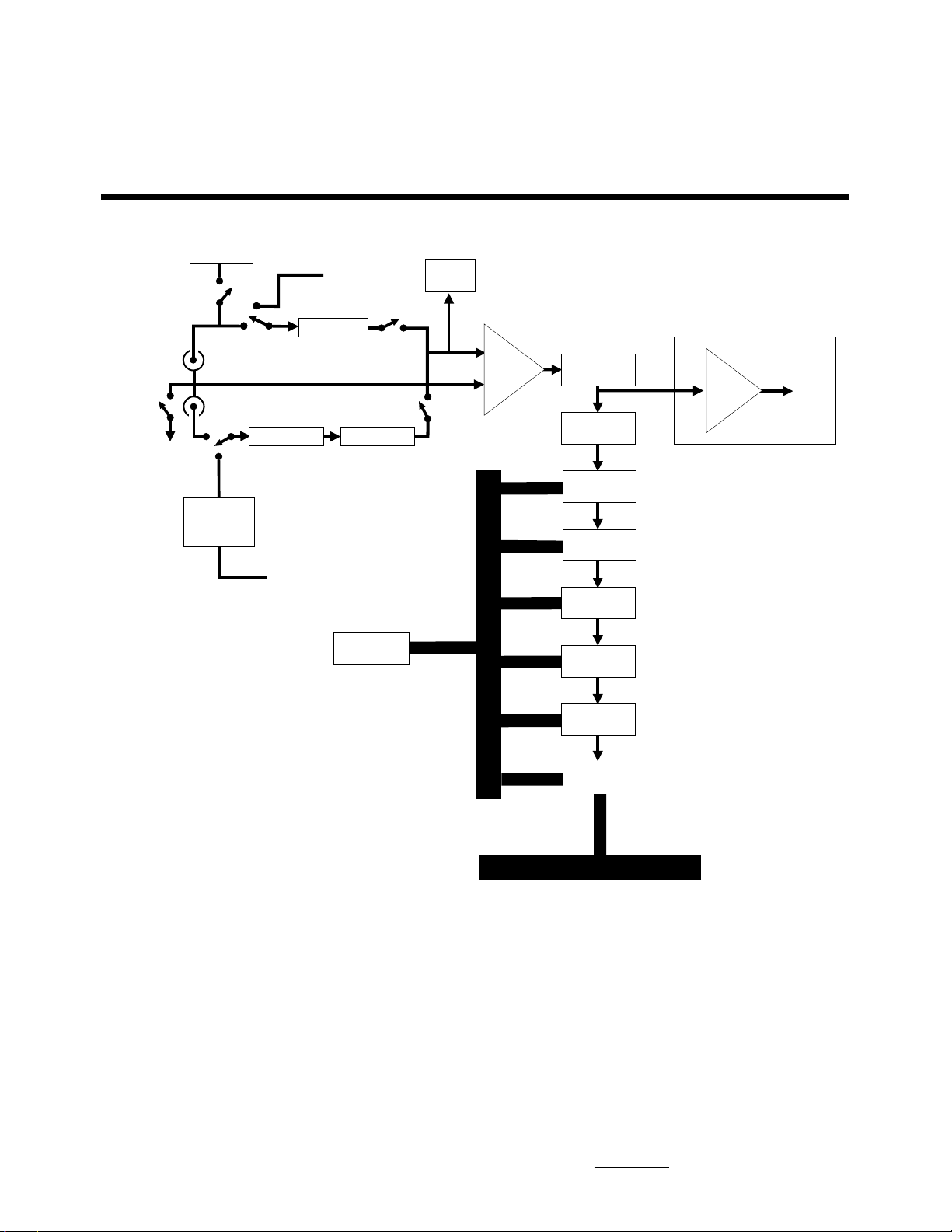
HP 35652A/B/ Input Modules
Float
±45 Vpk
Maximum
4mA
Voltage / 4 mA
Charge Input
100pF ±1%
Capacitor
Current
Source
Analog Cal Bus
Attenuators
Charge Amp
To System
Analog Cal Bus
To System
Attenuators
6809
Processor
Offset
DAC
Differential
Amp
Processor Bus
Anti-Alias
Filter
Sample
Hold
A/D
Converter
Trigger
Overload
LO
Digital
Filter
Buffer
Option 001
Analog
Output
±2 Vpk
Full Scale
8k word
FIFO
System Bus
Interface
System Bus
10
Page 11

HP 35652A/B
Specifications
Frequency Range
HP 35652A: dc to 51.2 kHz
HP 35652B: dc to 102.4 kHz
NOTE: Specifications do not apply
if anti-aliasing filter is bypassed.
Unless otherwise noted,
specifications do not apply when test
signal is applied to the low side of
inputs. Specifications do not apply if
cables are physically connected to
both voltage and charge inputs
simultaneously.
Voltage Input Accuracy
Single-Channel Amplitude:
Calibrated with the HP 35653C source cal signal and calibration
routine available with HP 35630B and 35635R software.
Frequency Input Ranges Accuracy
All frequencies 1.26 mVpk to 3.16 mVpk ± 0.25 dB
3.98 mVpk to 39.8 Vpk ± 0.15 dB
Uncalibrated; after correction for digital filters characteristics
Frequency Input Ranges Accuracy
0.1 Hz to 20 kHz 1.26 mVpk to 3.16 mVpk ± 0.5 dB
3.98 mVpk to 39.8 Vpk ± 0.3 dB
20 kHz to 50 kHz 1.26 mVpk to 3.16 mVpk ± 0.75 dB
3.98 mVpk to 39.8 Vpk ± 0.65 dB
HP 35652B:
50 kHz to 100 kHz All Ranges ± 0.8 dB
Channel-to-Channel
Amplitude and Phase:
Calibrated with the HP 35653C source cal signal and calibration
routine available with HP 35630B and HP 35635R software
Frequency Input Ranges Accuracy
0.1 Hz to 50 kHz 1.26 mVpk to 39.8 Vpk ± 0.1 dB
Frequency Input Ranges Accuracy
0.1 Hz to 50 kHz All Ranges ± 0.5 degrees
Uncalibrated; after correction for digital filters characteristics
HP 35652A/B:
Frequency Input Ranges Accuracy
0.1 Hz to 20 kHz 1.26 mVpk to 3.16 mVpk ± 1.0 dB
20 kHz to 50 kHz 1.26 mVpk to 3.16 mVpk ± 1.50 dB
50 kHz to 100 kHz All ranges ± 1.6 dB
Frequency Input Ranges Accuracy
0 Hz to 12.5 kHz All Ranges ± 7.5 degrees
12.5 kHz to 25 kHz ± 15.0 degrees
25 kHz to 50 kHz ± 30 degrees
3.98 mVpk to 39.8 Vpk ± 0.6 dB
3.98 mVpk to 39.8 Vpk ± 1.26 dB
Full Scale Ranges: 1.26 mVpk
11
Page 12

(Rs=0Ω, isolated mode)
Ranges 0 to 66 Hz 66 Hz to 1 kHz
1.26 mVpk to 398 mVpk >80 dB >70 dB
(dc coupling)
1.26 mVpk to 398 mVpk >70 dB >60 dB
(ac coupling)
501 mVpk to 3.98 Vpk >60 dB >50 dB
5.01 Vpk to 39.8 Vpk >40 dB >30 dB
Input Module Autozero modes:
(HP 35652A/B and HP 35655A/B)
ZERO compensates for offsets with the input hardware.
OFS adjusts the input so that fixed offset voltage at the input produces a
measurement with a zero dc input.
INP measures the dc value of the input at the time of the autozero and attempts
to adjust the front-end to reduce that dc value to zero.
BUCKOUT Applies an independent dc offset voltage of up to ±10 V to the
(HP 35655A/B BNC shell. Intended for use with 2.4 mA constant-current input mode.
ONLY)
(-58 dBVp) to 39.8 Vpk
(+32 dBVp) in 2 dB steps
Input Impedance:
High-to-low: 1MΩ ±5% (input
capacitance < 150 pF)
Low-to-case single ended:
(ground) 55Ω ±15Ω
Low-to-case isolated: (float)
1 MΩ nominal (input capacitance
< 10,000 pF)
Input Coupling: 3 dB ac roll off
< 1 Hz
Common Mode Rejection Ratio:
NOTE: In Buckout mode, the user is
causing the module to “buckout” the
dc offset of the signal going into the
HP 35655A/B. This is done by putting
a voltage on the “minus” (BNC shell)
input, so that the dc offset on the
“plus” input is near zero. The “plus”
input is then measured. The “minus”
input is kept at a low impedance,
much like the grounded input mode,
so that common mode signals will
not introduce inaccuracies into the
measurement.
Noise: (Rs=50 ohm, 16 averages)
20 to 200 Hz: < (565/√__(f) nVrms/√__(Hz)
(frequency dependent)
Above 200 Hz: < 40 nVrms/ √__(Hz)
(frequency independent, measured
on most sensitive range)
12
Page 13

Charge Input Accuracy
Channel-to-Channel
Amplitude and Phase:
Calibrated with HP 35653C source cal signal and calibration routine
available with HP 35630B and HP 35635R software
Frequency Input Range* Accuracy
At 1 kHz All Ranges ± 0.3 dB
At flatness to 50 kHz All Ranges ± 0.1 dB
Frequency Input Range Accuracy
0 Hz to 50 kHz All Ranges ± 0.5 degrees
Uncalibrated; after correction for digital filters characteristics
HP 35652A/B:
Frequency Input Range Accuracy
10 Hz to 20 kHz -18 to -10 dBpCp ± 1.2 dB
-8 to +72 dBpCp ± 0.8 dB
20 kHz to 50 kHz -18 to -10 dBpCp ± 1.7 dB
-8 to +72 dBpCp ± 1.5 dB
HP 35652B:
50 kHz to 100 kHz All Ranges ± 1.8 dB
Frequency Input Range Accuracy
0 Hz to 12.5 kHz All Ranges ± 7.5 degrees
12.5 kHz to 25 kHz ± 15.0 degrees
25 kHz to 50 kHz ± 30.0 degrees
* 0 dBpCp = 1pC (peak)
Single-Channel Accuracy:
(with full scale signals)
Calibrated with HP 35653C source cal signal and calibration routine
available with HP 35630B and HP 35635R software
HP 35652B:
50 kHz to 100 kHz All Ranges ± 0.8 dB
Frequency Input Ranges Accuracy
At 1 kHz -18 to -10 dBpCp ± 0.35 dB
-8 to +72dBpCp ± 0.25 dB
Flatness to 20 kHz -18 to +72 dBpCp ± 0.10 dB
Flatness to 50 kHz -18 to +72 dBpCp ± 0.15 dB
Uncalibrated; after correction for digital filters characteristics
HP 35652A/B:
Frequency Input Ranges Accuracy
10 Hz to 20 kHz -18 to -10 dBpCp ± 0.6 dB
-8 to +72 dBpCp ± 0.4 dB
20 kHz to 50 kHz -18 to -10 dBpCp ± 0.85 dB
-8 to +72 dBpCp ± 0.75 dB
HP 35652B:
50 kHz to 100 kHz All ranges ± 0.9 dB
Full Scale Ranges: 0.156 pC peak to
3981 pC peak
Input Impedance:
Low-to-Case: (single-ended mode)
55Ω nominal
Low-to-Case: (isolated mode) 1 MΩ
nominal (input capacitance
<10,000pF)
NOTE: These charge input
specifications apply only to
capacitive input devices with
maximum capacitance of 30,000 pF
and minimum shunt resistance of
10 MΩ.
Full Scale Charge Ranges:
0.126 pCpk (-18 dBpCp) to
3980 pCpk (+72 dBpCp) in
2 fB steps
Low Frequency Rolloff: 3 dB ac
rolloff <1.5 Hz
Common Mode Voltage Sensitivity:
(Cs=1000 pF, isolated mode)
Frequency Input Ranges Sensitivity
0 to 40 Hz -18 to +32 dBpCp <0.1 pC/V
40 to 66 Hz -18 to +32 dBpCp <0.01 pC/V
66 Hz to 1 kHz -18 to +32 dBpCp <0.03 pC/V
Noise: (Cs=1000 pF, 16 averages)
20 to 200 Hz: < (620 x 10
Above 200 Hz: <45 x 10
+34 to +52 dBpCp <1.0 pC/V
+54 to +72 dBpCp <10 pC/V
+34 to +52 dBpCp <0.1 pC/V
+54 to +72 dBpCp <1.0 pC/V
+34 to +52 dBpCp <0.3 pC/V
+54 to +72 dBpCp <3.0 pC/V
-6
√__(f) pCrms/√__(Hz)
(frequency dependent)
-6
pCrms/√__(Hz)
(frequency independent)
13
Page 14

Voltage or Charge Inputs
Option 001: Analog Output
Abbreviations
Common Mode Range: –4.0 to
4.0 Vpk (isolated mode)
Dynamic Range:
(Rs = 50Ω, Cs=1000 pF,
16 averages, relative to full scale,
charge amp range ≥ 0)
Internal sample clock:
80 dB 0-51.2 kHz
(HP 35652A/B)
75 dB 51.2 to102.4 kHz
(HP 35652B)
External sample clock:
65 dB all spans
Transducer Power Supply
Current:
4 mA nominal
Voltage:
26V nominal (open circuit)
Load Impedance: >4 kΩ, <600 pF
Output Connector: BNC female
Output Level (full-scale input
to voltage or charge inputs,
1 kHz, independent of range):
2 Vpk ±0.12V (+6 dBVp
±0.5 dB)
Output Amplitude Flatness
(uncalibrated, relative to 1 kHz):
<±0.7 dB, 10 Hz to 50 kHz
Output Impedance: <80Ω
Output Polarity (ref. to
HP 35652A voltage input):
Noninverting
Output Dynamic Range
(Rs = 50Ω, Cs = 100 pF, 16
averages, internal sampling):
20 Hz to 50 kHz = 70 dB
relative to full scale
dBVp - dB relative to 1 volt peak
dBpCp - dB relative to 1 pico-
coulomb peak
nVrms/
√√
√
Hz - nano-volts
√√
rms per square root hertz
pCrms/
√√
√
Hz - pico-coulombs
√√
rms per square root hertz
Rs - resistance of source or
termination connected to an input
Cs - capacitance of source or
termination connected to
charge amplifier
f - bin frequency in hertz
Triggering
Modes: Freerun, input
Trigger signal level range:
±125% of full scale range
Resolution: ±0.031% of
full scale range
Ranging
Range modes:
fixed, single autorange
With the charge amplifier set to a
range below 0 dBpCp, the following specification applies:
20 Hz to 50 kHz = -70 dBpCp
Output DC Offset (ref. to 0 Vdc
at HP 35652A/B voltage input)
Input Ranges Nominal
3.98 mVpk to 39.8Vpk ±500 mV
14
Page 15
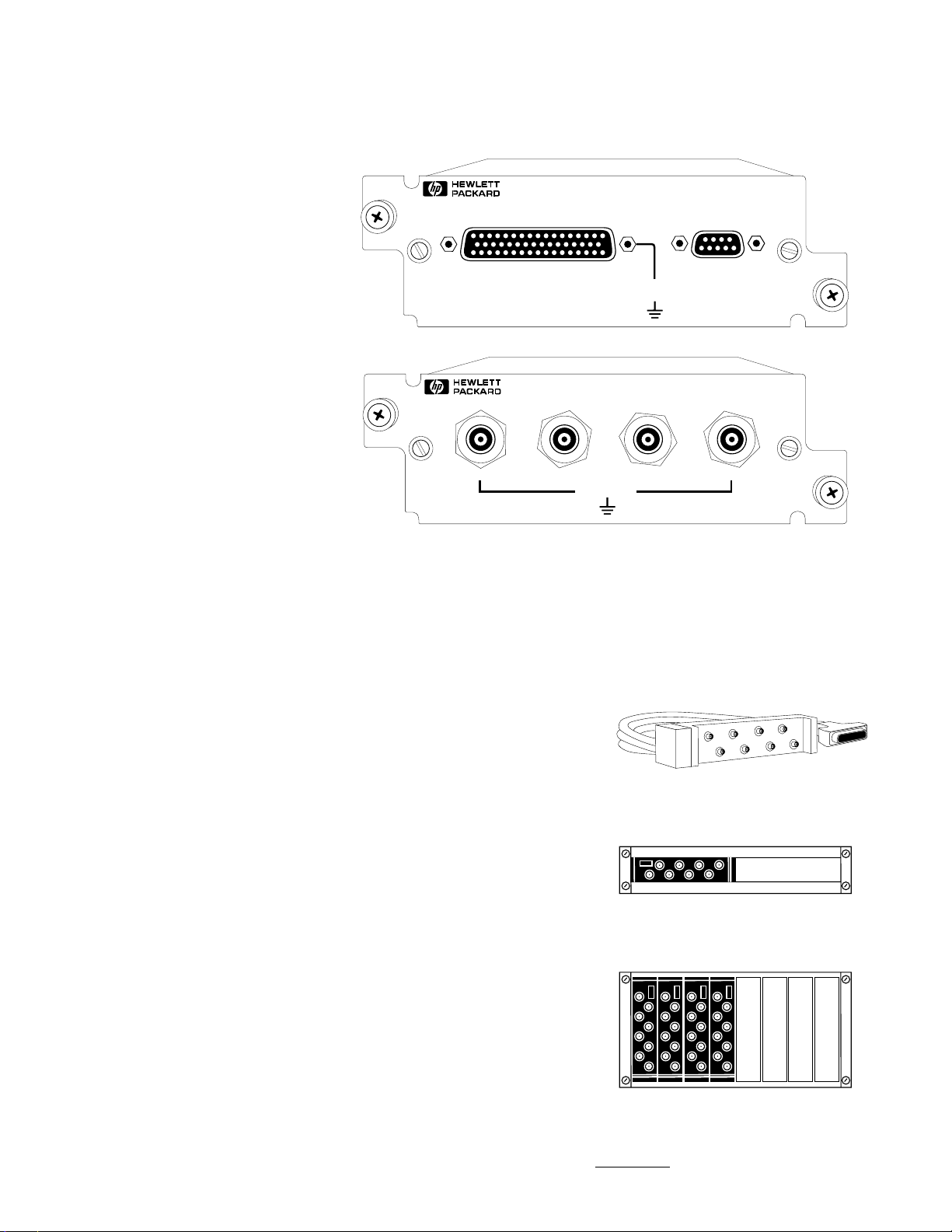
HP 35655A 8-Channel Input Module
HP 35655B 4-Channel Input Module
The HP 35655A provides eight
separate analog input channels
in one plug-in module. The
HP 35655B provides four separate
analog input channels in one
plug-in module. Aside from the
channel count, the two modules
have the same specifications.
Each input channel is sampled
simultaneously. The maximum
span is 12.8 kHz. While input
circuitry for each channel is
separate, hardware for digital
filtering, zooming, and trigger
detection and delay is common to
all eight inputs. Thus, parameters
such as measurement span and
trigger delay are the same for all
channels.
Other module features include:
• Two input modes: voltage and
IEPE constant-current
• Full scale input ranges from
5 mV to 10 V in 2 dB steps
• Anti-alias protection on all spans
• Auto-ranging
• Digital zoom capability on all
channels and all spans
• 72 dB dynamic range
•Buffered analog output on all
input channels
* NOTE: The IEPE mode provides a
2.4 mA constant current supply for
transducers. To operate with the
HP 35655A module, IEPE transducers
must be isolated from ground.
35655A
12.8 kHz
8 CHANNEL INPUT
INPUT
35655B
12.8 kHz
4 CHANNEL INPUT
CH 1 CH 2 CH 3 CH 4
The HP 35655A module comes
with one eight-input BNC breakout box (6 ft cable), one eightoutput BNC breakout box for the
analog outputs and a rack mount
kit (HP 35655-00200). Option 905
substitutes microdot breakout
boxes.
An HP 46298C 1600mm rack is
recommended to house rackmountable breakout boxes for
HP 35655A input modules. An
HP 46298C rack can hold up to 16
rack panels (equivalent to 256
channels). A special eight vertical
slot rack kit (HP 35655-C02) is
also available.
Specifications:
NOTE: HP 35655A input performance
specifications apply only if the
module’s analog output is turned off
(default is off). All specifications are
measured at module front panel
connector.
FLOAT
MAX 10V PK
OUTPUT
FLOAT
MAX 10V PK
BNC breakout box
35655 - 61600 BNC
35655 - 61601 micro dot
The HP 35655-00200
shown with one
breakout box installed
Frequency
Range: dc to 12.8 kHz
Spans and block sizes: see page 4
The HP 35655-C02
shown with four
breakout boxes
installed
15
Page 16
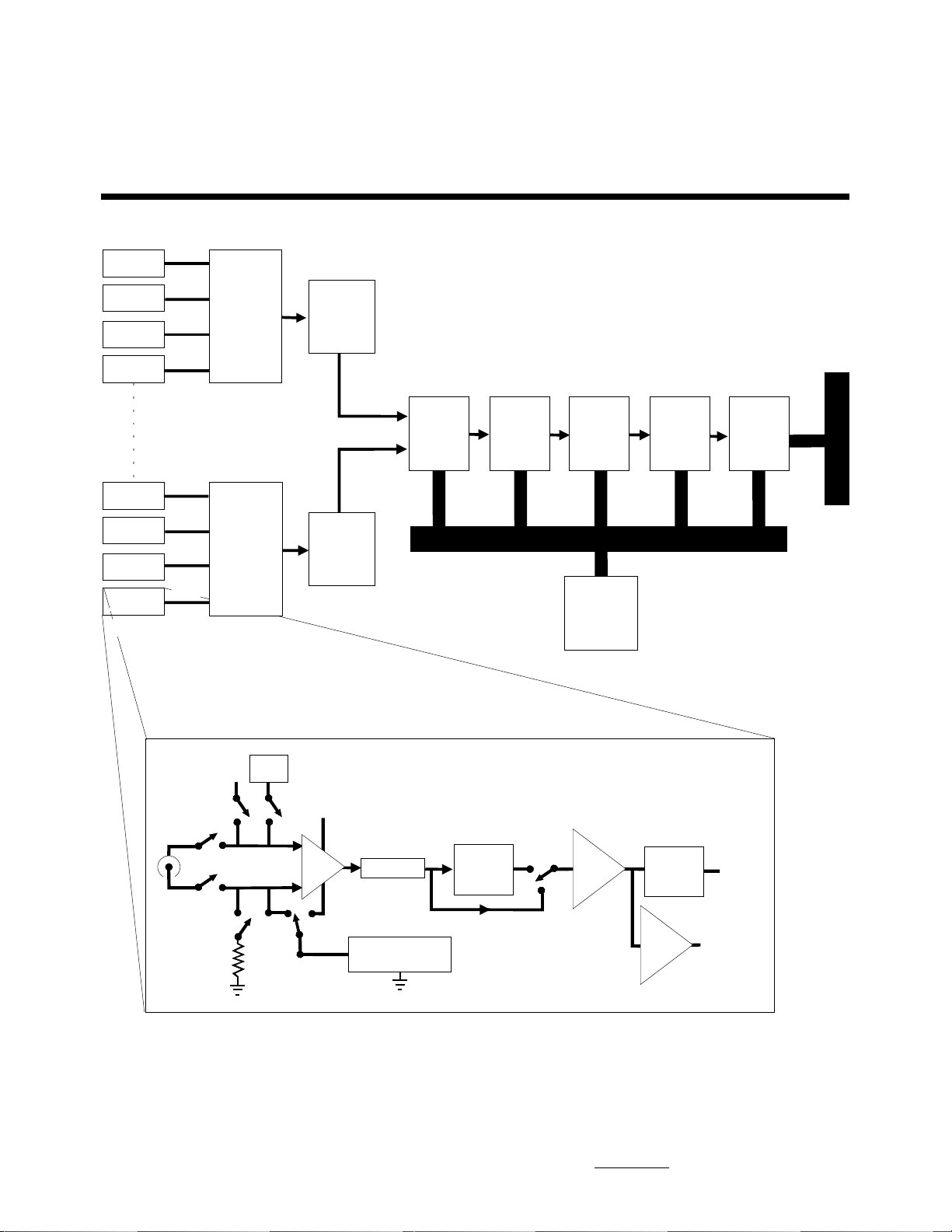
HP 35655A 8-Channel Input Module
(1 of 8)
Block A
CH 0
Block A
(8 0f 8)
CH 2
CH 4
CH 6
CH 1
CH 3
CH 5
CH 7
4to1
Multiplexer
4to1
Multiplexer
A/D
Converter
(13 bits)
A/D
Converter
(13 bits)
Trigger/
Overload
Digital
LO
Digital
Filter
Processor Bus
68000
Processor
8k word
x8CH
FIFO
System
Bus
Interface
System Bus
To System
Block A
Analog
Cal Bus
Input
2.4mA
Buckout
Gain
Select
Inst
Amp
Autozero/Offset
Offset/Autozero/
Channel Front End (1 of 8)
Attenuator
Anti-Alias
Filter
(12.8 kHz)
Buckout DAC
Buffer
Amp
16
Sample/
Hold
Buffer
Amp
Analog
Output
Page 17
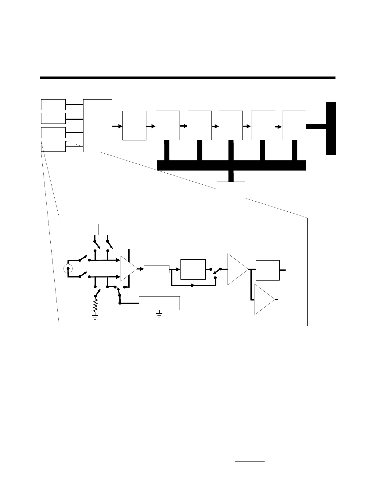
HP 35655B 4-Channel Input Module
(1 of 4)
Block A
CH 1
Block A
(4 of 4)
CH 2
Multiplexer
CH 3
CH 4
To System
Analog
Cal Bus
Input
4to1
2.4 mA
Buckout
A/D
Converter
(13 bits)
Gain
Select
Inst
Amp
Autozero/Offset
Offset/Autozero/
Trigger/
Overload
Channel Front End (1 of 4)
Attenuator
Anti-Alias
Filter
(12.8 kHz)
Buckout DAC
Digital
LO
Digital
Filter
Processor Bus
68000
Processor
Buffer
Amp
8k word
x8CH
FIFO
Sample/
Hold
Buffer
Amp
System
Bus
Interface
System Bus
Analog
Output
Block A
17
Page 18

Voltage Input Accuracy
Single-Channel Amplitude:
(relative to 1 kHz full scale sine wave input)
Calibrated with HP 35653C source cal signal and calibration routine
available with HP 35630B and HP 35635R software
Frequency Input Range Accuracy
All 20 dBvp to -46 dBVp ± 0.15 dB
Uncalibrated; after software correction
of digital filter characteristics
Frequency Ranges Accuracy
30 Hz to 2 kHz All Ranges ± 1.05 dB
2 kHz to 12.8 kHz All Ranges ± 1.8 dB
Full Scale Range: 5 mVpk (–46 dBVp)
to 10 Vpk (+20 dBVp) in2 dB steps
Input Resistance (IEPE source off,
dc coupled or ac coupled above
1 Hz) High or low to case,
differential mode: 1 MΩ ±5%
Input Capacitance (IEPE source off)
High or low to case: <200 pF
AC Coupling: 3 dB ac rolloff <1 Hz
Common Mode Rejection Ratio (dB):
(Rs = 0Ω, differential mode)
Channel-to-Channel Amplitude and Phase Accuracy:
Calibrated with HP 35653C source cal signal and calibration routine
available with HP 35630B and HP 35635R software
Amplitude Phase
± 0.1 dB ± 0.5 degree
Uncalibrated; after software correction
of digital filter characteristics
Frequency Ranges Accuracy
1 kHz All Ranges .25 dB nominal
Phase: (signal level > -40 dBfs, at 1 kHz) ±1.0 degree
Frequency Input Ranges Accuracy
0 to 66 Hz -46 to -22 dBVp >80 dB
(dc coupled) -20 to -2 dBVp >74 dB
0 to +20 dBVp >58 dB
66 Hz to 1 kHz -46 to - 22 dBVp >60 dB
(dc coupled) -20 to -2 dBVp >50 dB
0 to +2 0 dBVp >34 dB
47 to 66 Hz All Ranges >45 dB
(ac coupled)
Dynamic Range: 72 dB
(16 averages, Rs = 50Ω, common
mode signal < +20 dBfs)
Harmonic Distortion:
(relative to full-scale sine wave input)
Ranges Frequency Accuracy
-46 to +8 dBVp All (internal sampling <-72 dB
All (external sampling) <-60dB
+10 to +20 dBVp <1.3 kHz (internal sampling) <-72 dB
<1.3 kHz (external sampling) <-60 dB
>1.3 kHz <-154 + 20 Log
(freq)+range dB
Intermodulation Distortion:
(relative to two -6.02 dBfs in-band sine wave input signals)
Ranges Frequency Accuracy
-46 to +8 dBVp All (internal sampling) <-72 dB
+10 to +20 dBVp <2.6 kHz (internal sampling) <-72 dB
All (external sampling) <-60 dB
<2.6 kHz (external sampling) <-60 dB
>2.6 kHz <-160 +20 Log
(freq)+range dB
18
Page 19

Channel-to-Channel Crosstalk
(50Ω source, 50Ω termination on
all unused channels, relative to
full scale signal on offending
channel):
IEPE Current Source Off:
<MAX(-72 dBfs, -123 dB)
IEPE Current Source On:
<MAX (-72 dBfs, -110 dB)
Autozero Modes: see
HP 35652A/B specifications
on page 12.
Common Mode Range
(differential mode): Absolute
maximum signal level of either
high or low terminal, with respect
to chassis, including signal, common mode voltage, and noise
shall not exceed: ±10 Vpk
Noise (measured on most sensitive range):
20 to 1000 Hz (frequency dependent):<2260/√
>1000 Hz (frequency independent): <70 nVrms/√
__
(f) nVrms/√__(Hz)
Abbreviations
The following abbreviations are
used in the previous specifications:
dB - decibel
dBVp - dB relative to 1 volt peak
dBfs - dB relative to full scale
nVrms/
√√
√
Hz - nano-volts rms per
√√
square root hertz
__
(Hz)
Spurious or Residual Responses:
(in-band input signal, full scale)
Int. Sample Clock: <-72 dBfs
Ext. Sample Clock: <-60 dBfs
Transducer Power Supply
Current: 2.4 mA nominal
(into 50 Ω)
Maximum Voltage: 24 V nominal,
relative to shell of BNC
Note: IEPE transducer must be
isolated from ground to achieve
+24 volts open circuit. When IEPE is
turned on, the shell of the BNC is
pulled to -10 volts, requiring ground
isolation of the transducer.
Analog Output
fs - full scale
Rs - resistance of source or
termination connected to an input
Vs - voltage level of source
connected to an input
MAX(x,y) - the specification is the
greater of the two values, x and y
Output Level for Any Full-Scale
Input: 2 Vpk nominal
Output Impedance: 2 kΩ
19
Page 20
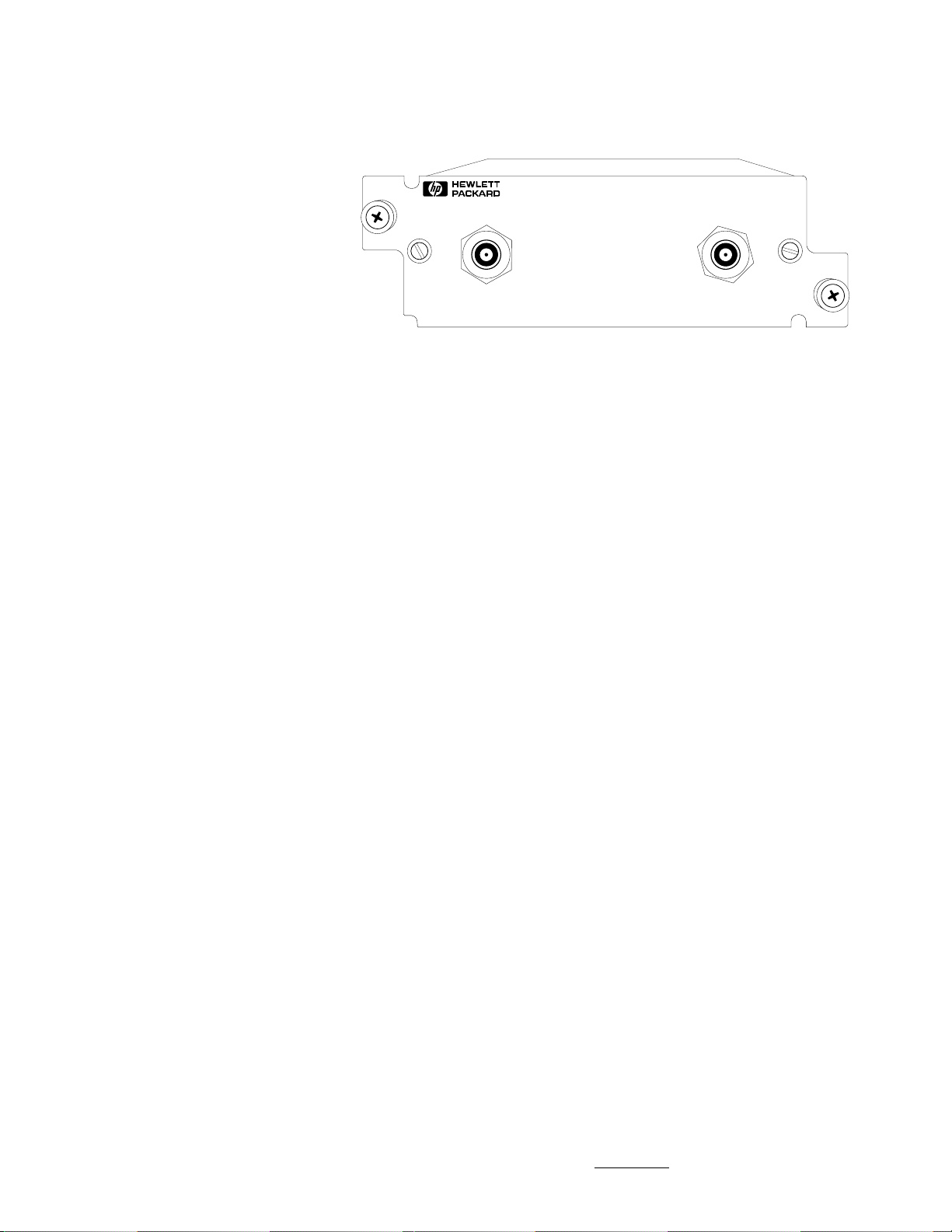
HP 35653C Source Module
The HP 35653C source module
provides the excitation signals
needed for a wide variety of
stimulus/response measurements.
The module’s output modes
include:
• An uncorrelated band-limited and
band-translated random noise
stimulus
• A variable burst random stimulus
• Burst sine (single frequency) and
impulse outputs
• A reference signal for system
calibration of input modules
• Programmable phase control at
0°, 90°, 180°, 270°
• Hard-wired switch to guarantee
100% compatibility with the
obsolete HP 35653A
35653C
102.4 kHz
SOURCE MODULE
SHUTDOWN OUTPUT
Specifications:
Amplitude
Output Level
AC Range: 1.26 mV (-58 dBVp) to
10.0V (+20 dBVp) in 0.375 dB
steps
Maximum Output Voltage:
(ac + dc) 10 V (RL > 10 kΩ)
Maximum Current: > 50 mA
(-8 V < Vout < +8 V)
Accuracy
±10% ±10 mV: 1 kHz sine,
RL > 10 kΩ, from 100 mVpk
(-20 dBVp) to 10 Vpk (+20 dBVp)
Random Noise Modes
Passband Flatness: ±3 dB
In-Band Energy: 70%
(amplitude = 10 Vpk,
center frequency= 5 kHz,
span = 800 Hz)
Crest Factor:
5 (typical; baseband)
7 (typical; zoomed, center
frequency > 70% of span)
Fixed Sine Mode
Flatness: ±1 dB (relative to level
at 1 kHz, ranges ≤16 dBVp);
+1, -3 dB (relative to level at 1 kHz,
ranges ≤16 dBVp)
DC Offset (RL > 10 kΩ)
Range: ±5V
Resolution: 2.5 mV
Accuracy: ±20 mV ±1% of Vout
(at 25°C)
Output Impedance: <1.2 Ω
Capacitive Load: 0.01 µF max
Harmonic and Subharmonic
Distortion (for signals > 1 volt):
< -35 dB
Pulse Mode
Pulse width: 1% to > 95% of time
record (typical; minimum pulse
width, block size of 1024 points)
Abbreviations
RL - Load resistance on
HP 35653C output
dBVp - dB relative to 1 volt peak
20
Page 21
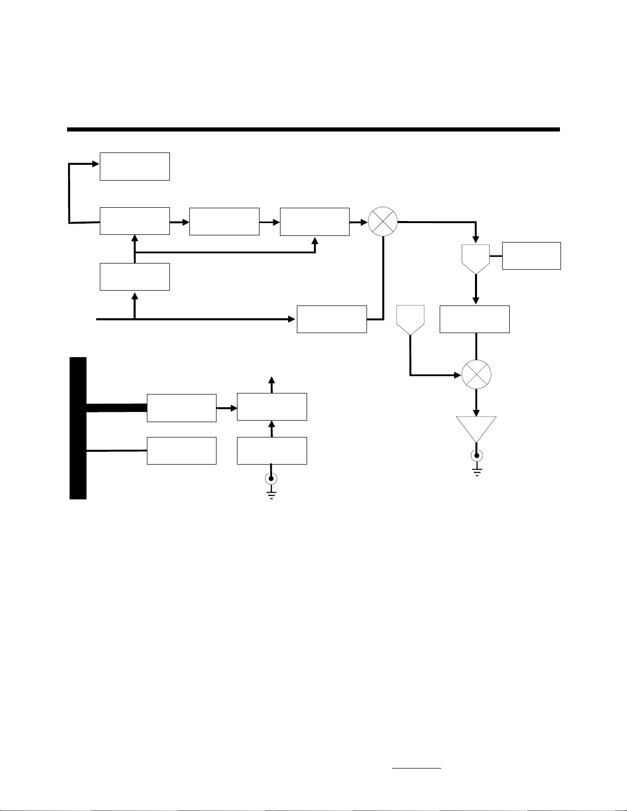
HP 35653C Source Module
Burst Counter
Noise Generator
Sample Rate
Generator
System Sample Clock FS
System Bus
System Bus
Interface
Calibrator
Burst MUX
6809 Processor
Shutdown
Shutdown
FIR Filter
Local OSC LP Buffer
DC
DAC
Gain Control
Buffer
Output
21
Page 22
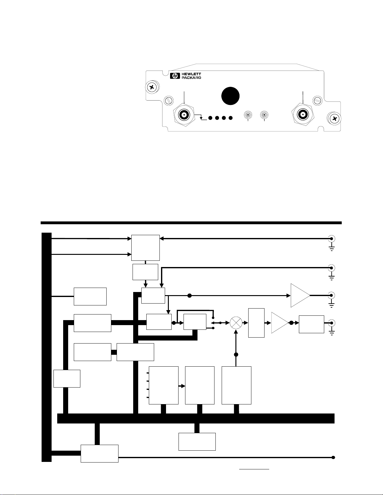
HP 35656B Programmable DAC Module
The HP 35656B is a digital-toanalog (DAC) source module that
can be programmed to generate
user-defined signals. Module
features are tailored to vibration
control applications:
• Signal DAC with 16 bits of
resolution
• Programmable range DAC
(16-bit resolution)
• Programmable data buffer size
(from 1 to 32,768 datawords)
• Programmable sample ∆t from
4 µsec to 64 sec
• Programmable output attenuators
(0 dB, -20 dB, -40 dB)
HP 35656B Block Diagram
FS
MCLK
35656B
PROGRAMMABLE DAC
SHUTDOWN DAC OUT
TTL LOW
DAC
CLKGPRDYSBRDY
• DC offset (after autozero):
< ± 2 mVolts
•Source rampdown time of
approximately 1.5 sec
• System shutdown via the external
TTL port or internal system bus
• External parallel interface to
allow downloading of data
directly from the host computer
3to1
Multiplexer
ERR
SUMMING
JUNCTION
INPUT
EXT
AUX
CLK
OUT
Specifications
Signal Output
Max. Voltage Level: ±10 Vpk
Max. Current: ±50 mA
Max. Output Impedance: 1.2 Ω
Max. Capacitive Load: 0.01 uF
Output Range: 0.1 Vp to 10 Vp
Ext. Clk.
Shutdown
Cal out
System Bus
Controller
2kwordsx16
0.8k wordsx24
FIFO
Calibrator
FIFO
Memory
System Bus
Interface
Timebase
Data
Stream
Controller
Signal
DAC
Range
DAC
A
B
Multiplexer
C
D
4to1
A
B
Low Pass
Filter
Offset
and
Selftest
ADC
Processor Bus
68000
Processor
Offset
DAC
Aux. Out
Buffer
0dB
-20dB
-40dB
Atten-
D
Buffer
DAC Out
Output
Protection
uator
C
LED
22
Page 23
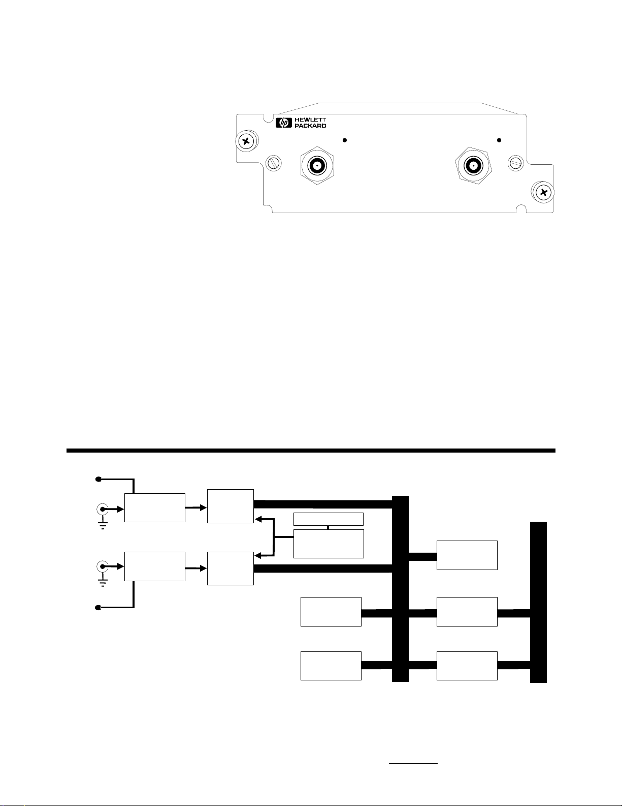
HP 35658A Tachometer/Trigger Module
The HP 35658A tachometer/
trigger module provides tach and
triggering information for use
with digital order tracking and
resampling software.The module
uses a 20 MHz counter to record
accurate tach or trigger times.
It can also be use to externally
trigger other measurements.
• Tachometer/trigger signal
conditioning
• Programmable tach/trigger levels
• Hysteresis to prevent false
tachs/triggers
• Trigger sources: time internal,
RPM internal, (run-up or
run-down), external
35658BA
TACHOMETER/TRIGGER MODULE
TAC H
INPUT
Specifications
Tach Pulses/Revolution: 0.00001
to 65,536
RPM Accuracy: ±100 ppm
RPM Range: 0.25 to 6,000,000 rpm
Tach Pulse Rate:
min: 4.762 mHz
max: 100 kHz
EXT TRIG
INPUT
Tach/Trigger level
Range: -25 V to + 25 V
Resolution: ≤ 5 V: 40 mV
> 5 V: 200 mV
Accuracy: ≤ 5 V: ±100 mV
> 5 V: ±5% ±0.5 V
Input
Impedance: > 20 k (typical)
Min. Trigger pulse width: 100 ns
Tach Hold Off Time:
min: 4.8 µs (1.6 µs steps)
Max: 50 ms (1.6 µs steps)
HP 35658A Block Diagram
LED
Tach
Input
Trigger
Input
LED
Analog
Conditioning
Analog
Conditioning
Latch
Latch
Clock (20 MHz)
20 MHz
Counter
RAM
128k x 16
Flash ROM
128k x 8
68340
Processor
FIFO RAM
Processor Bus
16kx16
System Bus
Interface
System Bus
23
Page 24
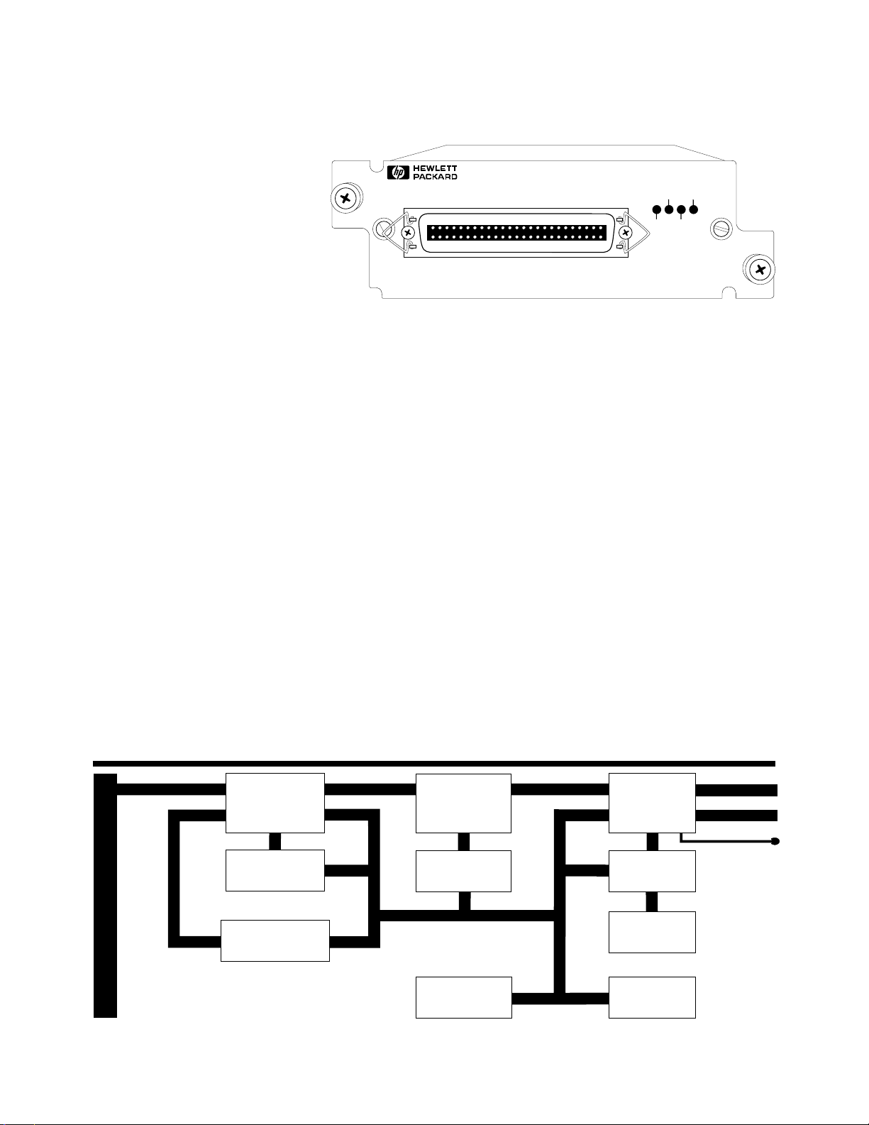
HP 35659A SCSI Interface Module
H
The HP 35659A module provides
high-speed throughput capability
for the HP 3565S system. Bypassing the signal processor module,
it takes data from the internal
high- speed system bus and
transfers it directly to selected
Small Computer System Interface
(SCSI) compatible mass-storage
devices or to an optional internal
hard disk. The module supports
trans-fer rates up to 2.6 MBytes/
sec (1.3 Msamples per sec).
The actual data transfer rate
is typically limited by the
storage device.
Features include:
•“Eavesdrop” mode takes data
directly from the system bus
while the signal processor module
uses its HP-IB connection for
other tasks.
• Monitor capability allows data
to be viewed during the
throughput session.
•Read mode takes data from
SCSI compatible devices and
puts it on the internal systembus
for the signal processor module
to process.
35659A
SCSI INTERFACE
• Multiple HP 35659A modules
can be installed in a system to
increase the maximum storage
size. Up to eight modules may be
in a system.
• The maximum system transfer
rate is 2.6 MBytes/sec, or
1.3 Msamples/sec with
option AT3.
• An optional internal 1 GByte
hard disk, option AT3, is fully
contained inside the module.
It functions as a target on the
SCSI network.
DISCSCSI
BUSYERR
Option AT3: Internal Hard Disk
Type: Magnetic Hard Disk
Size: 1 Gbyte (500 Msamples)
Throughput rate: 1.3 Msamples/sec
(2.6 Mbytes/sec)
Supported SCSI Mass
Storage Devices:
Model Type Size Max Rate*
HP 7979S Mag 323 MB 0.7 MB/s
HP C2214B Mag 1.3 GB 2.0 MB/s
HP C1520B Tape 2.0 GB 100 kB/s
HP C1521B Tape 8.0 GB 100 kB/s
* Transfer rates typical
SCSI Cables:
HP 92222A - 0.5 meter
HP 92222B - 1 meter
HP 92222C - 2 meters
(maximum cable length is 6 meters)
HP 35659A SCSI Interface Module
System Bus
Data
System Bus
Eavesdrop
System Bus
System Bus Status
and Command
Buffer Memory
512 kBytes, FIFO
Buffer Memory
Controller
ROM
256 kByte
SCSI
Interface
CPU (68340)
NOVRAM
512 Bytes
RAM
256 kBytes
Data subject to change.
Copyright © 1994, 1998 Hewlett-Packard Co.
Printed in U.S.A. 1/98
5966-3154E
Data
Control
LEDs
 Loading...