

Simulation and Measurement-based X-parameter Models for Power Amplifiers with Envelope Tracking 5991-2733EN [7]
Agilent Simulation and Measurement-based X-parameter Models for Power Amplifiers with Envelope Tracking 5991-2733EN [7] Datasheet
Page 1

Keysight Technologies
Simulation and Measurement-based
X-parameter Models for Power Ampliers
with Envelope Tracking
White Paper
www.keysight.com
www.keysight.com/find/contactus
This information is subject to change without notice.
Published in USA, August 3, 2014
5991-2733EN
Page 2
Simulation and Measurement-based X-parameter Models
for Power Amplifiers with Envelope Tracking
Haedong Jang1, Andrew Zai2, Tibault Reveyrand3, Patrick Roblin1, Zoya Popovic2, and David E. Root4
1
The Ohio State University, Columbus, OH
2
Un
iversity of Colorado, Boulder, CO
3XLIM-UMR CNRS, Limoges Cedex, France
4
Keysight Technologies, Inc., Santa Rosa, CA
Abstract —Static X-parameter (XP) models for RF power
amplifiers (PAs), derived from both simulations and nonlinear
vector networ k analyze r ( N VNA) measure ment s, ar e invest ig a ted
for the prediction of PA performance under dynamic signal
conditions s uch as in enve lope tracking (ET). The inst antaneous
AM-AM, AM-PM and PAE predictions of XP models extracted
from simulation are compared under ET dynamic signal
conditions to two types of circuit models using envelope
simulation. An XP PA model is extracted for a peak 8W GaN
class-F
-1
ET PA from NVNA measurements w ith automated bias
control. B y applying a consta nt gain shaping table derived fr om
the XP model to the drain supply voltage, the average PAE is
improved from 40% to 57% for 3.84 MHz WCDMA signals at
2.14 GHz compared to fixed drain bias operation.
Index Terms — X-parameters, envelope tracking, loadpull,
power amplifiers, supply modulation.
I. INTRODUCTION
High data rate communication requires spectrally efficient
complex modulation schemes such as WCDMA and LTE,
resulting in signals with high peak to average power ratios
(PAPR). These dynamic signals significantly degrade the
average PA efficiency when operated at a fixed bias condition.
The envelope tracking (ET) architecture has shown significant
improvement of the average efficiency by dynamically
adjusting PA supply voltages according to look-up tables
(LUT), or shaping tables, that specify mappings from input RF
time-varying envelopes to drain control signals on the PA [1].
Nonlinear characterization and modeling of the transistor
that can predict PA performance under varying bias and load
is needed for more complex transmitters, such as those that
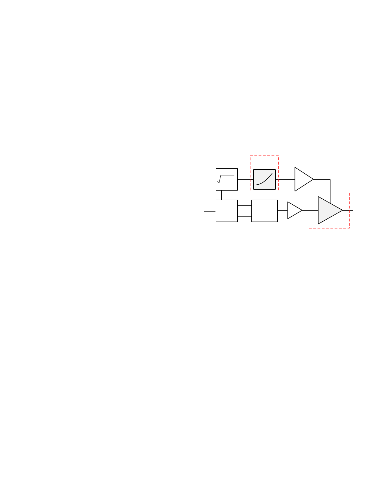
employ envelope tracking [2]. A simplified ET block diagram
is shown in Fig. 1 with a nonlinear RF PA that can be viewed
as a three-port device, with the third port being the supply
input. Most transistor and PA models are not designed with
dynamic bias taken into account. Assuming the device under
test (DUT) is quasi-static to the varying supply voltages a nd
the envelope tracker is ideal, the common PA performance
figure of merits (FOMs) such as AM-AM, AM-PM and PAE,
can be determined using the conventional static
characterization at multiple supply voltages. The goal of this
work is to develop a model for this application t hat is easy to
extract from simulations and standard measurements for the
shaping table design, and validate that it gives good estimates
of the PA performance under dynamic bias operation.
In this work, bias dependent static X-parameter (XP)
behavioral models [3][4] are developed from simulations and
from nonlinear vector network analyzer (NVNA)
measurements to model the nonlinear RF PA for use under
dynamic signal operation with supply modulators. Properties
of the bias dependent static X-parameter models are
summarized in section II. In section III, the FOMs of the static
model are compared to those of circuit models using dynamic
input signals. In section IV, a static XP model is extracted
from an S-band class-F
-1
GaN PA. A shaping table is designed
from the model and used to define dynamic drain control
signals to improve efficiency. The intended FOMs based on
the static model are measured under the dynamic ET condition
using the supply modulator from [1].
Furthermore, the performance prediction of a model with
varying loa ds is critic al for LU T designs a nd PA perfo rmance
optimizations under antenna mismatch condition [5]. The load
dependency prediction of the XP models including harmonic
loads [6] is validated by comparing the XP model, extracted
from NVNA measurements in 50Ω, to time-do main loadpull
data from an independent measurement system. Then the
Fig. 1. Simplified ET-PA system block diagram with a
nonlinear three-port RF PA.
A
Envelope
Tracker
RF PA
Driver
Envelope
Shaping
Delay
align
Envelope
Detection
RF
up-convert
I
Q
Q
I
12
3
I
2
+ Q
2
© 2013 IEEE. Personal use of this material is permitted. Permission from IEEE must be obtained for all other uses, in any current or future media, including reprinting/republishing
this material for advertising or promotional purposes, creating new collective works, for resale or redistribution to servers or lists, or reuse of any copyrighted component of this work
in other works.
978-1-4673-2141-9/13/$31.00 ©2013 IEEE
Page 3
effect of the load variation on the shaping table design is
presented.
II. B
IAS DEPENDENT XP MODEL
In the frequency domain, the scattered m
th
harmonic
component at port p is expressed by (1) at static RF conditions
at controlled DC bias conditions [3][4][6]. The model is
characterized over a large set of drain voltages and a wide
range of RF powers of the input driving signal. For timevarying bias and modulated RF input signals, the XP models
approximate the PA behavior through the quasi-static
approximation by evaluating (1) with time-varying arguments
when simulated in the envelope domain.
()
()
()
∑
∑
+
−
+
+
=
*
,11
)(
,,,
,11
)(
,,,
11
)(
,,
,
,
,
nq
nmT
nqmp
nq
nmS
nqmp
mF
mpmp
APADCX
APADCX
PADCXB
(1)
The additional S and T terms linearly estimate the effect of
the incident n
th
harmonic and its conjugate from the port q to
the scattered harmonic of interest, effectively predicting the
PA performance with varying load nearby the load where the
X-parameters were extracted. This has been demonstrated to
be accurate for power amplifier applications where
perturbations are relatively small compared to the large
driving signal [6]. Extraction tones were applied in the
measurements for the identification of those terms. The
amplitude of the tones was selected 16 dB lower than the main
large tone for proper linear approximation. Evenly distributed
four phases were used to acquire the conjugate component.
Phases of respective harmonic components are normalized
relative to the input large signal by the P term.
III. S
IMULATION-BASED XP MODELING
In this section, two types of static XP behavioral models are
generated from PA models in the Agilent ADS simulator
using contin uous wave (CW) RF e xcitation at dif ferent static
drain bias conditions. Then the XP models and the underlying
circuit models are compared under modulated RF signal
conditions, first under fixed bias conditions and second under
dynamic supply modulation conditions applied using a draincontrol LUT based on the XP model.
The PA circuit model is based on a silicon MOSFET
transistor model, biased at V
gs
=1.75 V for class AB operation
with 27.9 dBm output power at 1 dB compression. XP models
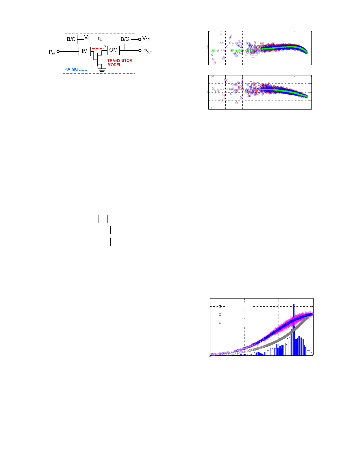
were extracted in two different cases, as shown in Fig. 2. In
case (1), the entire matched amplifier, including the transistor
model and bias and matching networks, is converted into an
XP model. The input power was swept from -10 to 26 dBm to
model the PA in saturated operation. The drain voltage was
swept from 1.5 to 6 V for ET design resulting in a three
terminal nonlinear model. In case (2), the bare transistor
model was converted into a load-dependent XP model, and the
circuitry for bias and matching are embedded around the XP
transistor model. The input power range and loads used for the
XP extraction of the bare transistor are different from that of
the whole PA. The input power range for the bare transistor
XP extraction was from -20 to -1 dBm. Instead of 50Ω, the
Fig. 2. Two different XP models were extracted from a circuit
model. (1) An XP model was extracted from the entire P A (blue)
(2): XP model was extracted only of the transistor (red) and then
embedded in matching (IM, OM) and bias circuitry (B/C).
0 10 20 30
0
20
40
60 X-par(ET)
Ckt(ET)
Ckt(Fxd)
PAE (%)
P
out
(dBm)
Fig. 4. Simulation results for an LTE signal and a CMOS PA
under ET operation compared to fixed bias condition operation.
Both XP model and circuit model show improved efficiency.
The XP model estimates the ET performance improvement over
static bias very closely to that of the circuit model. A histogram
of the LTE si
g
nals is shown for reference.
0 5 10 15 20 25 30
-5
0
5
AM-AM (dB)
0 5 10 15 20 25 30
-40
-20
0
20
40
P
out
(dBm)
AM-PM (
°
)
Fig. 3. AM-AM, AM-PM simulation results for LTE UL
signals at fixed bias conditions. The XP model for the whole
amplifier (green), XP model of bare transistor (blue)
embedded in the matching and bias circuitry of the PA, the
circuit model (red).
978-1-4673-2141-9/13/$31.00 ©2013 IEEE
Page 4
load seen from the transistor, Γ
0.79157.6 , was
estimated from the circuit model and applied to the drain of
the transistor. Also, the load was swept around the selected
point with 0.1 step for the magnitude and 3° for the phase.
The dynamic AM-AM, AM-PM envelope simulation results
using LTE uplink signals at fixed bias conditio ns for the XP
models and the underlying circuit models are shown in Fig. 3.
The signals were generated using 16 QAM modulations with 5
MHz bandwidth. When the whole PA circuit model was
replaced by the XP model as in case 1 (green), no gain and
phase spreading is observed for the time-varying signals as
with the detailed circuit model (red). However, the average
gain and phase, which corresponds to the static nonlinearity of
the XP model, is well-represented. When only the transistor
was replaced by the XP model, case 2 (blue), the
instantaneous signal follows well the results of the circuit
model (red). The spreading can be concluded to come
primarily from the bias and matching networks in this
example. It should be noted that only the input signal induced
dynamic effects are present with the fixed bias while both
input and supply induced dynamics are present under ET.
A LUT for ET operation of the PA was designed using
static gain curves as functions of drain voltage predicted by
the XP model of the entire PA. The envelope simulation
results of the XP model under ET operation and fixed bias
conditions with the above LTE signals are compared to the
circuit model in Fig. 4. The average PAE simulated, using the
XP model, was 43.3% (ET) compared to 31.5% (fixed bias)
which is very close to the results obtained from the circuit
model of 42.4% (ET) compared to 31.7% (fixed bias) for the
same average output power of 24 dBm for a fair comparison.
ADS examples showing envelope tracking may be
downloaded from [7].
IV. M
EASUREMENT BASED X-PARAMETER EXTRACTION AND
EXPERIMENTAL VALIDATION
X-parameters of a class-F
-1
GaN HEMT 8-W PA [8], based
on a TriQuint TGF2023-02 transistor, were measured at
2.14GHz in CW mode using an NVNA. The NVNA
automatically characterized and generated an X-parameter
model as a function of drain voltage and RF power. The Xparameter s were measured in a nominall y 50Ω system. Five
harmonics of the scattered waves, magnitudes and phases,
were measured. The drain voltage varied over the range 12 to
30 V. Auxiliary amplifiers were used for both input and output
to boost the source power. External couplers were used with
additional attenuators considering peak powers. The input
power was swept from 0 to 25 dBm. The extraction tones were
selected to be 16 dB lower than the peak operating power for
both input and output with 4 phases.
In order to verify the XP model extracted from the NVNA
frequency domain measurement instrument, the DUT was
measured at various bias and load conditions on an
independent time domain loadpull system - a VTD (now
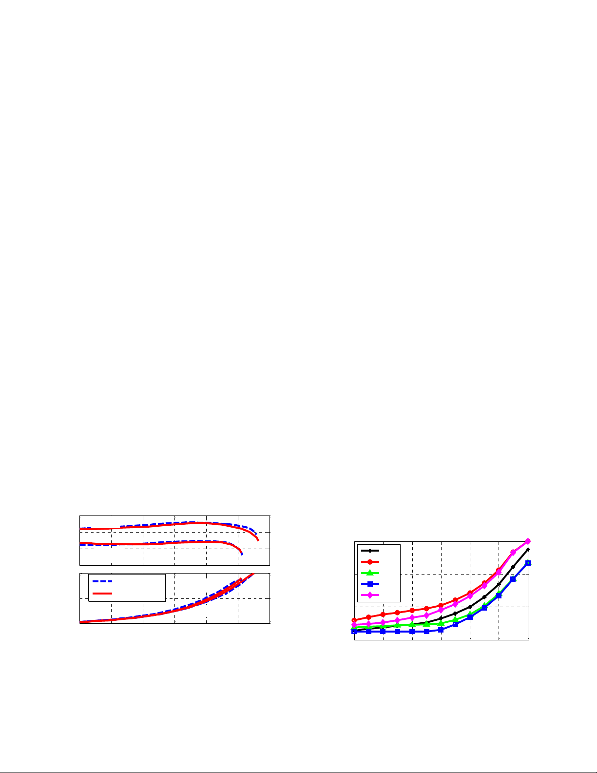
Agilent) sampler-based SWAP-X402. In Fig. 5, gain and PAE
versus output power curves are compared at two different
loads, specified in the caption, at a fixed drain bias of 28V.
The XP model, generated from measurements into fixed
impedance of nominally 50Ω was able to track the significant
load-dependent performance characteristics of the amplifier,
without the need for a load tuner. Given the fidelity of the
load-dependent XP model predictions, additional load
variation effects on the LUT design were investigated. Fig. 6
illustrates just how much the corresponding LUT for constant
gain ET operation depends on load, for four different complex
reflection coefficients of |Γ| ≤ 0.1.
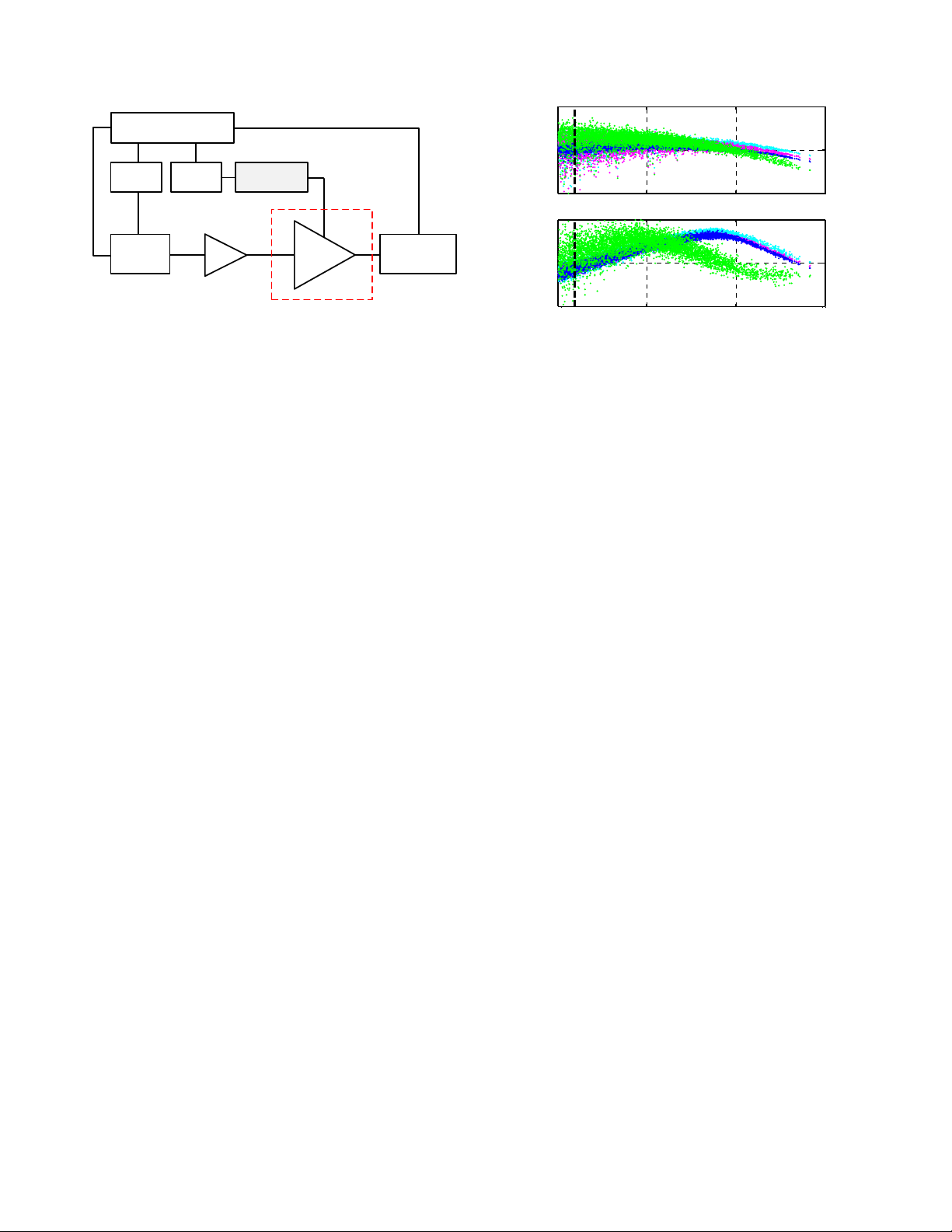
The PA performance under ET conditions, based on the
static XP model, was measured using a WCDMA signal as
shown in Fig. 7. The test signal, with duration of 1 ms and
3.84 MHz bandwidth, was generated and the LUT was applied
to the signal to generate the drain supply control signal. This
control signal was fed to the supply modulator using an
arbitrary waveform generator. The original WCDMA signal
was up-converted by an ESG and fed to the input of the PA
through a linear driver amplifier. In-phase and quadrature
phase data from input and output ports were recorded. The
operation, at fixed bias conditions of 26 V, 28 V and 30 V,
Fig. 5. PA gain and PAE versus power at two different loads
at fixed V
dd
=28 V. Predictions from the NVNA measurementbased XP model (red), verification by measured results (blue)
using a sampler-based SWAP ti me-domain loadpull system.
Load A: Γ
0.17311.2°. Load B: Γ
0.293178.8°).
14
18
22
Gain (dB)
load A
load B
10 15 20 25 30 35 40
0
40
80
P
out
(dBm)
PAE (%)
load A
load B
SWAP m ea s
XP model
12 14 16 18 20 22 24
18
22
26
30
Pin (dBm)
V
dd
(V)
0
-j0.1
-0.1
j0.1
0.1
Fig. 6. The constant-gain LUT dependence on fundamental
load, computed from the measured and val idated XP model, is
quite significant, even for reflection coefficient magnitu des as
small as 0.1.
978-1-4673-2141-9/13/$31.00 ©2013 IEEE
Page 5
was also measured for comparison. The signal sources were
synchronized by sharing a 10 MHz reference.
The measured average PAE under ET condition excluding
the supply modulator was 57.8 % with 31.28 dBm output
power while the PAE of the three fixed bias cases showed
40.3 % in average with 30.6 dBm average output power. The
measured average drain voltage during the ET operation was
21V, which is well below the fixed bias conditions. The
designed average output power was 28.8 dBm.
As shown in Fig. 8, ET operation showed more gain
compression above 18 dBm than the fixed bias conditions.
The AM-PM characteristics under ET operation show wider
spreading. We expect that some of this spreading can be
attributed to increased memory effects under dynamic biasing
different from the assumption of ideal linear operation. A
systematic characterization of the supply modulator could be
developed to consider the imperfect modulator characteristics
into the design.
V. C
ONCLUSION
Simulation-based and measurement-based frequency
domain static XP models were investigated specifically for
envelope tracking power amplifiers. The envelope simulation
and measurement results show good quantitative agreement
for the static nonlinearity of the PA versus power and drain
voltage, and also as a function of load. A new result is the
load-sensitivity of the lookup table predicted by the XP model
that was independently validated by time-domain loadpull
measurements. It is expected that the static X-parameter based
end-to-end measurement-based design flow should meet the
commercial specifications, at least for amplifiers not
exhibiting significant long-term memory effects.
As future work, limitations of the quasi-static app roach can
be explored by treating the RFPA as a mixer, with the bias pin
treated as a second large signal incommensurate with respect
to the RF input tone. Another approach would use the
dynamic extensions of X-parameters [9] applied to both the
RF and the supply ports.
A
CKNOWLEDGEMENT
This work was supported by a Grassroots grant from
Agilent Technologies and in part by ONR under the DARPA
MPC Program N00014-11-1-0931. The authors thank A.
Howard, J. Horn, R. Biernacki, M. Marcu, P. Cain, A.
Cognata, and J. Xu for support and valuable discussions.
R
EFERENCES
[1] J. Hoversten, S. Schafer, M. Roberg, M. Norris, D. Maksimovic,
and Z. Poppovic, “Co-design of PA, supply, and signal
processing for linear supply-modulated RF transmitter,” IEEE
Trans. Microwave Th eory & Tech., vol. 60, no. 6, June 2012.
[2] P.M. Asbeck. H. Kobayashi, M. Iwamoto, G. Hanington, S.
Nam, L.E. Larson, “Augmented behavioral characterization for
modeling the nonlinear response of power amplifiers,” IEEE
MTT-S Intl Microwave Symp. Dig., 2002
[3] J. Verspecht, and D.E. Root, “Polyharmonic distortion
modeling,” IEEE Microwave Magazine, vol. 7, no. 3, Jun e 2006.
[4] D. E. Root, J. Verspecht, D. Sharrit, J. Wood, and A. Cognata,
“Broad-band, poly-harmonic behavioral models from fast
automated simulations and large-signal vectorial network
measurements,” IEEE Trans. Microwave Theory & Tech., vo l.
53, no. 11, November 2005. pp. 3656-3664
[5] R. Paul, L. Sankey, L. Corradini, Z. Popovic, and D.
Maksimovic, “Power management of wideband code division
multiple access RF power amplifiers with antenna mismatch,”
IEEE Trans. on Power Electronics, Vol. 4, No. 4, Apr. 2010
[6] J. Horn, D. E. Root, and G. Simpson, “GaN device modeling
with X-parameters,” IEEE CSICS Oct. 2010.
[7] http://edocs.soco.agilent.com/display/eesofkcads/Applying+
envelenv+tracking+to+Improve+Efficiency
[8] M. Roberg, J. Hoversten, and Z. Popovic, “GaN HEMT PA
with over 84% power added efficiency,” Electronics Letters,
Vol. 46, No. 23, Nov. 2010
[9] J. Verspecht, J. Horn, L. Betts, D. Gunyan, C. Gillease and D.E.
Root, “Extension of X-parameters to include long-term dynamic
memory effects,” IEEE MTT-S Int. Micro. Symp. Dig. June 2009
Fig. 7. The baseband WCDMA signal was generated by
arbitrary signal generator (ARB) 1 and fed to a RF signal
generator. ARB 2 generates shaped drain control signal and fed
to the envelope tracker. A signal analyzer recorded 1 ms long
baseband complex data.
ARB 2
Signal
Generator
RF PA
12
3
ARB 1
Signal
Analyzer
Driver
Envelope
Tracker
Matlab
10 15 20 25
5
15
25
Gain (dB)
10 15 20 25
-30
0
30
Pin (dBm)
AM-PM (
°
)
Fig. 8. The measured ET (green) gain and phase variations
are compared to the fixed bias (cyan: 30V, pink: 28 V, blue:
26V) conditions with WCDMA down link signal. The supply
voltage does not vary for input power levels below the black
dashed line.
978-1-4673-2141-9/13/$31.00 ©2013 IEEE
 Loading...