

Page 1
Keysight Technologies
Pulse Parameter Denitions
Application Note
Page 2
Introduction
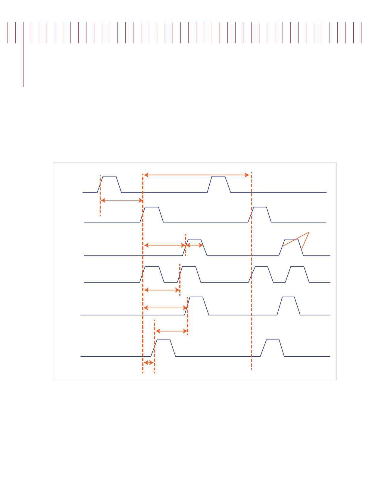
Electrical pulses are used to synchronize, trigger or control multiple electrical devices in a test
system. Pulses are also used for clock generation or radar testing. In order to describe a pulse
and make its creation repeatable, a set of parameters has been dened. This document describes
and illustrates all main pulse parameter denitions. It is a collection of terms used in the test and
measurement environment. The information will help the reader to understand the nature of a
pulse, and will make instrument specications comparable amongst each other.
External
trigger signal
Trigger
output
Output
Trigger
delay
Pulse
delay
Pulse period
Pulse
width
Transition
times
Double pulse
output
Channel A
output
Channel B
output
Figure 1. Overview of the pulse parameters
Double pulse delay
Delay A
Interchannel
delay skew
Delay B
Page 3
Time Reference Point
0%
50%
100%
Median
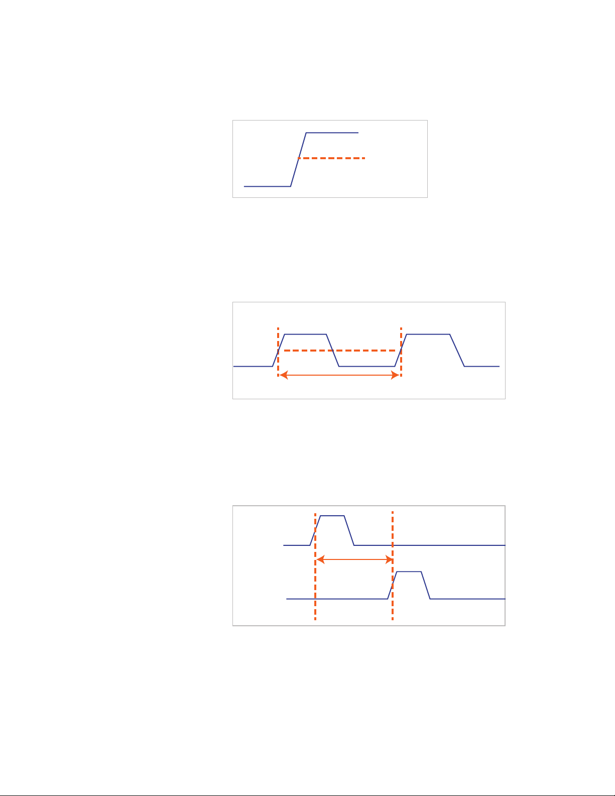
The time reference point is at the median of the amplitude (50% amplitude
point on pulse edge).
100%
Figure 2. Time reference at median amplitude
Figure 3. Pulse period
50%
Median
0%
Pulse Period
The time interval between the leading edge medians of consecutive
output pulses.
50%
Pulse period
Trigger Delay
Figure 4. Trigger delay
Interval between trigger point of the external trigger input signal and the
trigger output pulse’s leading-edge median.
External
trigger signal
Trigger
delay
Trigger
output
3
Page 4

Figure 5. Pulse width
Pulse Width
Interval between leading- and trailing-edge medians. The specified and displayed
value is that obtained with fastest edges, essentially equal to the interval from
the start of the leading edge to the start of the trailing edge. By designing so that
the pulse edges turn about their start points, the interval from leading-edge start
stays unchanged (in practice, start points may shift with changes in transition
time) when transition times are varied. This is more convenient for programming
and the width display is easy to interpret.
50%
Specified
width
Pulse Levels
Pulse output is specified as pulse top and pulse base (usually referred to as high
level and low level), or as peak to peak amplitude and median offset. A “window”
specification shows the limits within which the pulse can be positioned.
Figure 6. Pulse levels
Amplitude
Low level
High level
Zero volts
Median
Max high level
Offset
Min low level
Window
4
Page 5
Pulse Delay
50%
Specified
width
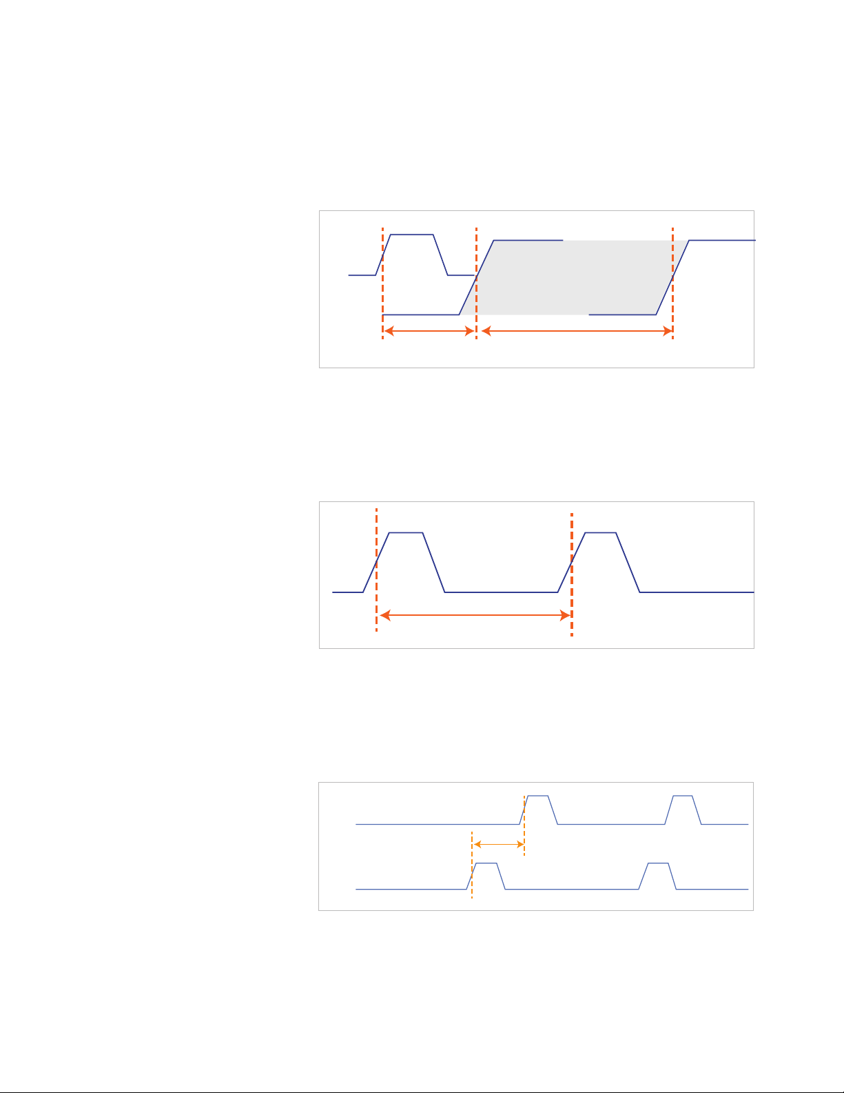
Interval between leading edge medians of trigger output pulse and output pulse.
The specified and displayed value is that obtained with the fastest leading edge.
Pulse delay has two components, a fixed delay from trigger output to output
signal and a variable delay with respect to the trigger output.
Trigger
output
Output
signal
Figure 7. Pulse delay
Figure 8. Double pulse delay
Fixed delay
Variable delay
Double Pulse Delay
Interval between leading edge medians of the double pulses.
Double pulse delay
Interchannel Delay (Skew)
Figure 9. Interchannel delay
Interval between corresponding leading-edge medians of the output signals.
Channel A
output
Interchannel
delay skew
Channel B
output
5
Page 6
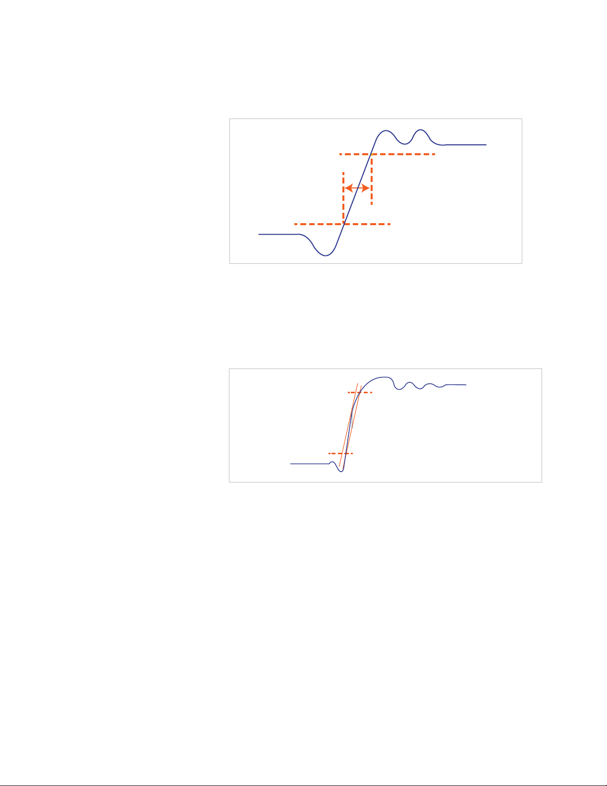
Figure 10. Transition time
Double pulse delay
Transition Time
Interval between the 10%- and 90%- amplitude points on the leading/trailing edge.
100%
90% amplitude
Transition
time
10% amplitude
0%
Linearity
Peak deviation of an edge from a straight line through the 10%- and 90%amplitude points, expressed as percentage of pulse amplitude.
Figure 11. Linearity
90% amplitude
Deviation
10% amplitude
0% amplitude
100% amplitude
Jitter
Short-term instability of one edge relative to a reference edge. Usually specified
as rms value, which is one standard deviation or “sigma”. If distribution is
assumed Gaussian, six sigma represents 99.74% of the peak-peak jitter.
The reference edge for period jitter is the previous leading edge. That for delay
jitter is the leading edge of the trigger output. Width jitter is the stability of the
trailing edge with regard to the leading edge.
Stability
Long-term average instability over a specific time, for example, hour, year.
Jitter is excluded.
6
Page 7
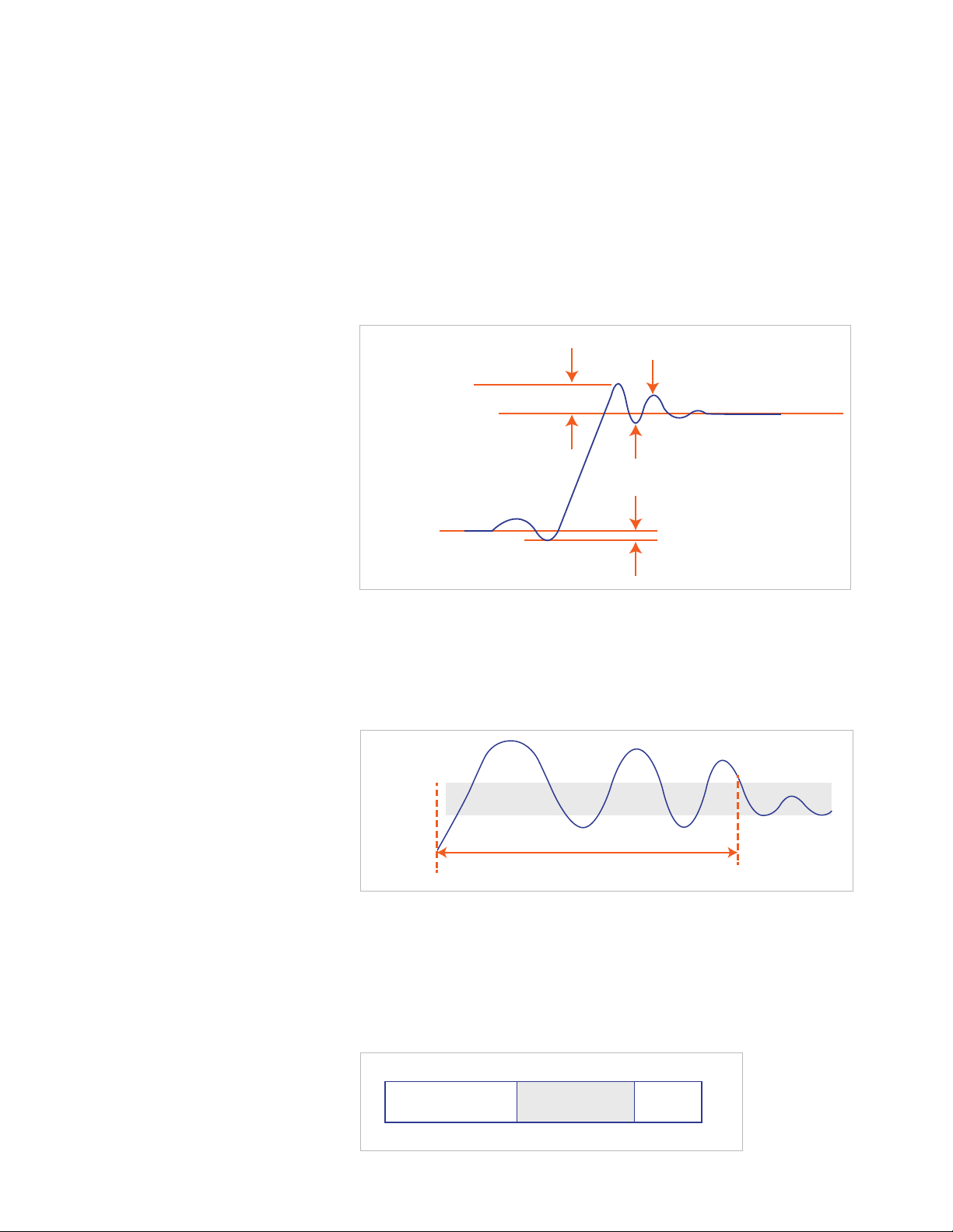
Preshoot, Overshoot, Ringing
Accuracy window
Repeatability band
Settling time
90%
amplitude
Amplitude
accuracy
band
Preshoot and overshoot are peak distortions preceding/following an edge.
Ringing is the positive-peak and negative-peak distortion, excluding overshoot,
on pulse top or base. A combined preshoot, overshoot, and ringing specification
of e.g. 5% implies:
– Overshoot/undershoot < 5%
– Largest pulse-top oscillation
– < +5%, of pulse amplitude
Figure 12. Preshoot, overshoot, ringing
Overshoot
(e.g., 5%)
Ringing
(POSITIVE)
(e.g., +3%)
100%
amplitude
Ringing
(NEGATIVE)
(e.g., -2%)
0%
amplitude
Preshoot
(e.g., 2%)
Settling Time
Time taken for pulse levels to settle within level specifications, measured from
90% point on leading edge.
Figure 13. Setting time
Figure 14. Repeatability
90%
amplitude
Settling time
Amplitude
accuracy
band
Repeatability
When an instrument operates under the same environmental conditions and
with the same settings, the value of a parameter will lie within a band inside the
accuracy window. Repeatability defines the width of this band.
7
Page 8

08 | Keysight | Pulse Parameter Denitions - Application Note
myKeysight
www.keysight.com/find/mykeysight
A personalized view into the information most relevant to you.
www.keysight.com/go/quality
Keysight Technologies, Inc.
DEKRA Certified ISO 9001:2008
Quality Management System
Keysight Channel Partners
www.keysight.com/find/channelpartners
Get the best of both worlds: Keysight’s measurement expertise and product
breadth, combined with channel partner convenience.
www.keysight.com/pulse_generator
www.keysight.com/find/pulse_generator
www.keysight.com/find/81150
www.keysight.com/find/81160
For more information on Keysight
Technologies’ products, applications or
services, please contact your local Keysight
office. The complete list is available at:
www.keysight.com/find/contactus
Americas
Canada (877) 894 4414
Brazil 55 11 3351 7010
Mexico 001 800 254 2440
United States (800) 829 4444
Asia Pacic
Australia 1 800 629 485
China 800 810 0189
Hong Kong 800 938 693
India 1 800 112 929
Japan 0120 (421) 345
Korea 080 769 0800
Malaysia 1 800 888 848
Singapore 1 800 375 8100
Taiwan 0800 047 866
Other AP Countries (65) 6375 8100
Europe & Middle East
Austria 0800 001122
Belgium 0800 58580
Finland 0800 523252
France 0805 980333
Germany 0800 6270999
Ireland 1800 832700
Israel 1 809 343051
Italy 800 599100
Luxembourg +32 800 58580
Netherlands 0800 0233200
Russia 8800 5009286
Spain 0800 000154
Sweden 0200 882255
Switzerland 0800 805353
Opt. 1 (DE)
Opt. 2 (FR)
Opt. 3 (IT)
United Kingdom 0800 0260637
For other unlisted countries:
www.keysight.com/find/contactus
(BP-07-10-14)
This information is subject to change without notice.
© Keysight Technologies, 2013 - 2014
Published in USA, August 3, 2014
5991-1943EN
www.keysight.com
 Loading...