

Page 1
Probing Solutions for Logic Analyzers
Product Overview
Create a Quality Connection to Your
Target System
To make sure you have the tools
for dependable state and timing
measurements, no matter what
mix of chip packages, test ports
and probes your application
requires, we’ve created the
largest line of probing solutions
in the industry.
Accurate measurements start
with reliable probing. Agilent
Technologies offers a wide variety
of probing accessories to support
your measurement needs, making
it easy to connect your Agilent
logic analyzer to your design.
Each is designed for a specific
measurement need because the
physical and electrical quality of
the connection can mean the difference between a good measurement and a bad one.
Table of Contents
Reliable Connections
Ensure Accuracy. . . . . . . . . . . . . . . . . . . . 2
Which Logic Analyzer? . . . . . . . . . . . . . 3
Quick Selection Guide . . . . . . . . . . . . . . 4
Selecting the Optimum
Probing Strategy. . . . . . . . . . . . . . . . . . . . 5
For All Agilent Logic Analyzers with
40-pin Pod Connectors . . . . . . . . . . . . . . . . . 5
For All Agilent Logic Analyzers with
90-pin Pod Connectors . . . . . . . . . . . . . . . . . 7
For the Agilent 16517A and 16518A
Logic Analysis Modules . . . . . . . . . . . . . . . . 8
General-Purpose Probing . . . . . . . . . . . . 9
For All Agilent Logic Analyzers with
40-pin Pod Connectors . . . . . . . . . . . . . . . . . 9
General-Purpose Probing. . . . . . . . . . . 12
QFP Package Probing . . . . . . . . . . . . . . 14
Designing and Probing with
Target Connections . . . . . . . . . . . . . . . . 17
Normal-Density, Medium-Performance
Applications . . . . . . . . . . . . . . . . . . . . . . . . . 17
For All Agilent Logic Analyzers with
40-pin Pod Connectors . . . . . . . . . . . . . . . . 18
Probing Individual Pins of
High-Density Connectors. . . . . . . . . . . . . . 30
Designing and Probing with
Target Connections . . . . . . . . . . . . . . . . 31
Designing and Probing with
Target Connections . . . . . . . . . . . . . . . . 32
Agilent Logic Analyzers with
90-pin Pod Connectors . . . . . . . . . . . . . . . . 32
Agilent 16760A 1.5 Gbits/Sec
Logic Analyzer Module. . . . . . . . . . . . . . . . 37
Agilent Logic Analyzers with
90-pin Pod Connectors . . . . . . . . . . . . . . . . 38
General-Purpose Probing. . . . . . . . . . . 40
Agilent Logic Analyzers with
90-pin Pod Connectors . . . . . . . . . . . . . . . . 40
Agilent 16517A/16518A
1 GHz State / 4 GHz Timing . . . . . . . . . 45
Ordering Information . . . . . . . . . . . . . . . 47
Related Information . . . . . . . . . . . . . . . . 52
Support, Services, and Assistance. . . 53
About this Document
To assist you in choosing the best
state/timing probing solution for
your particular target, this document will consider the following:
• Chip packaging, test ports
• Special physical and electrical
considerations
• Other accessories and options
Other Reference Documents
For information on probes and
accessories for the other related
Agilent Technologies logic
analysis system products listed
below, please refer to “Related
Information” in this document:
• Pattern generators
• Emulators
• Oscilloscopes
Page 2

2
• Impedance
High input impedance
ensures minimum intrusion on
your circuit. Although many
probes might be acceptable for
lower frequencies, capacitive
loading becomes significant at
higher frequencies. The
Agilent Technologies probing
products perform over a wide
frequency spectrum.
• Ruggedness
Probes with quality
mechanical design provide
solid electrical connections.
Intermittent open circuits
would only add one more
variable to your debugging
equation. Agilent probes
are mechanically designed
to relieve strain and ensure
rugged, reliable connection.
• Immunity to Noise
Electromagnetic noise can
corrupt data captured by
the logic analyzer. Agilent
probing solutions are
designed for a high immunity
to transient noise.
• Performance
Agilent logic analyzers have
front-end circuitry that
supports the state and
timing specifications of
the analyzer. This circuitry,
together with the Agilent
probing solutions described in
this document, will accurately
capture the target signals at
the specified clock rates.
Reliable Connections Ensure Accuracy
Signal Frequency Content Drives Probing Solutions
Faster clock rates demand tighter timing tolerances, such as setup
and hold specifications. Systems with faster clock rates usually
have shorter rise and fall times. Signals with shorter transition
times have more high frequency content and are more susceptible
to high frequency analog problems such as cross talk, reflections,
ground bounce, noise and emissions. Susceptibility of a system to
analog problems relates to the transition times of the signals, not
the clock rate. A system with slow transition times cannot have
high clock rates. However, it is possible for a system with slower
clock rates to have signals with very fast transition times.
General-purpose probing solutions provide the analog bandwidth
required to run each logic analyzer module at its maximum clock
rate. The high input impedance of these probes, especially at high
frequencies, presents a minimal load to most systems. Systems
that are operating with little margin should be designed with
consideration for both the system components and the input
impedance of the probing solution being used during debug.
Input impedance specifications or equivalent load diagrams
can be found for each of the probing solutions described in
this document.
For measurements at state speeds above 400 Mbits/second, and
for differential signals, Agilent has developed a new connectorless
probing system that is used with the Agilent 16753A, 16754A,
16755A, 16756A, and 16760A logic analyzer measurement
modules. This probing system features capacitive loading
of only 0.7 pF. Refer to pages 32-33 for information on this
probing system.
Other Considerations
Physical connection compatibility
between various Agilent probes
may allow you to mix and
match a variety of probes and
accessories. However, a probe
accessory designed for slower
clock speeds will not deliver
high-speed target performance
simply because it is used with a
higher speed analyzer module.
Also, the serial connection of
multiple probe leads and/or
accessories will degrade
signal integrity.
Page 3

3
Agilent logic analyzers have
two methods of connection to
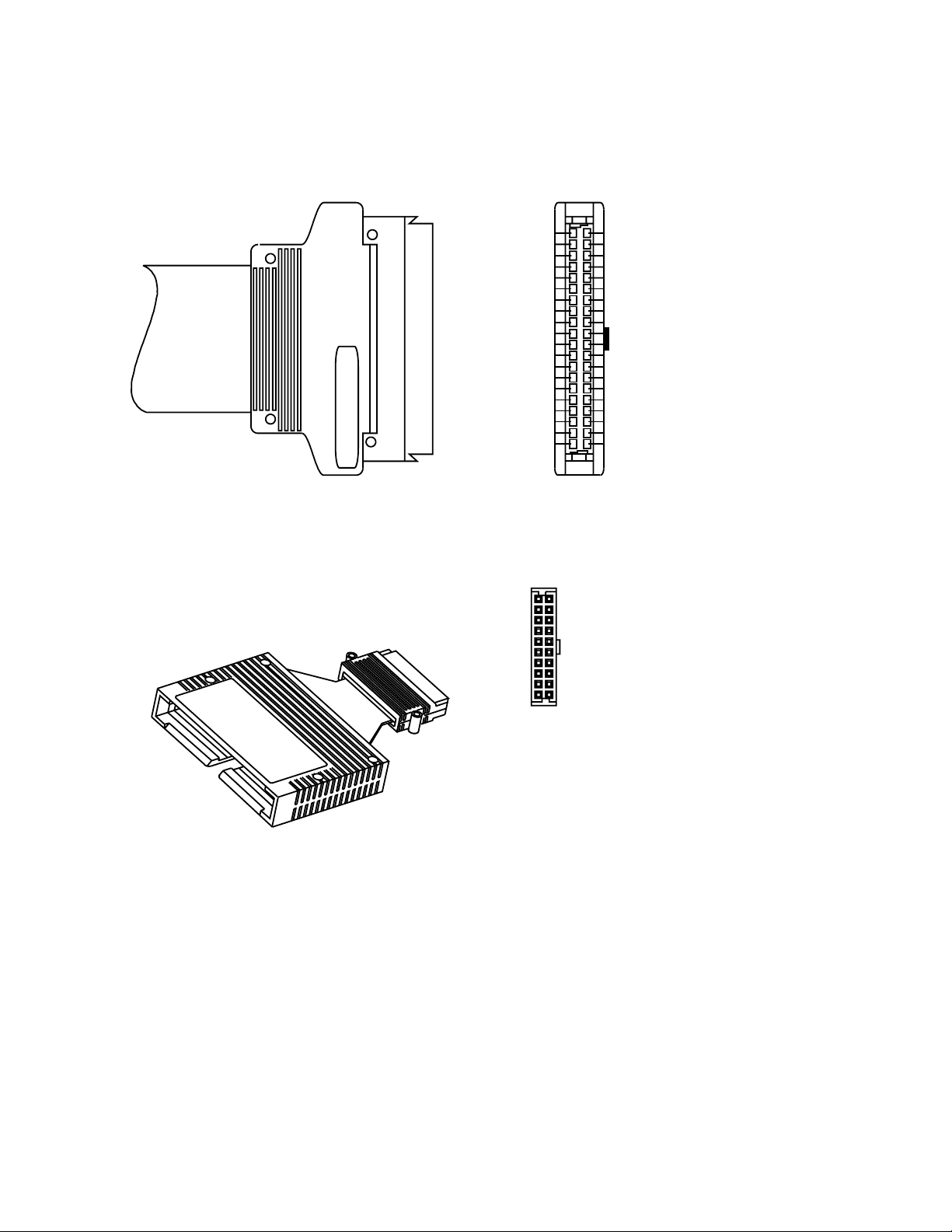
the probes. One uses a 3M-style
connector with 2 rows of 20
pins on 0.1-inch centers, as
illustrated in figure 1. Probes
for these analyzers are identified
in this document as “for analyzers
with 40-pin pod connectors.”
The other style uses a 90-pin,
high-density connector, as
illustrated in figure 2. Probes for
these analyzers are identified in
this document as “for analyzers
with 90-pin pod connectors.”
Currently available Agilent logic analyzers in these two groups are as follows:
40-pin pod connector 90-pin pod connector
1670 series logic analyzers 16753A
1680, 1690 series logic analyzers 16754A
16710A 16755A
16711A 16756A
16712A 16760A
16715A
16716A
16717A
16740A
16741A
16742A
16750B
16751B
16752B
The Agilent 16517A and 16518A (discontinued) do not use either of these connection systems. For discussions of the accessories available for the 16517A and 16518A, refer to pages [8] and [45-46]. [Page
numbers refer to the current version.]
Which Logic Analyzer?
Figure 1. 40-pin pod connector Figure 2. 90-pin pod connector.
Page 4

4
Quick selection guide
40-pin Flying leads Single-ended 17 01650-61608 9
40-pin 100-pin connector Single-ended 34 E5385A 23
40-pin 38-pin connector Single-ended 34 E5346A 23
40-pin 38-pin connector Single-ended, 34 E5339A 23
low voltage
40-pin 38-pin connector Single-ended, 34 E5351A 27
no isolation
networks
90-pin Flying leads Single-ended 17 E5382A 40
90-pin Flying leads Differential 17 E5381A 42
90-pin Soft touch Single-ended 34 E5390A 32
connectorless
90-pin Soft touch Differential 17 E5387A 32
connectorless
90-pin 100-pin Single-ended 34 E5378A 36
connector
90-pin 100-pin Differential 17 E5379A 36
connector
90-pin 38-pin Single-ended 34 E5380A 38
connector
* Isolation networks are included unless designated otherwise.
For logic
analyzer pod
connection
Connection
to system
under test
Single-ended*
or differential
Number of
channels
Agilent
model number
or part number Page
Page 5
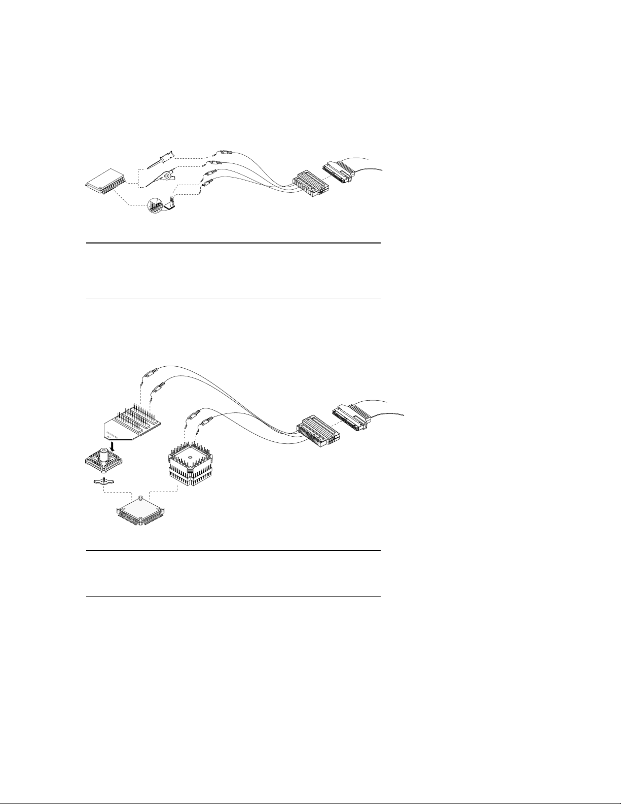
5
Selecting the Optimum Probing Strategy
For All Agilent Logic Analyzers with 40-pin Pod Connectors
Go to page 14 for a discussion of Agilent’s
QFP package probing solutions for logic
analyzers with 40-pin pod connectors.
Connecting to all the Pins of a Specific Package
Advantages Limitations
Most flexible method. Can be time-consuming to connect a large
Flying-lead probes are included with number of channels.
logic analyzer module. Least space-efficient method.
Some accessories may compromise
probe performance.
Go to page 9 for a discussion of Agilent’s
flying-lead logic analysis probes and
accessories for logic analyzers with
40-pin pod connectors.
Connecting to Individual IC Pins or Test Points
Advantages Limitations
Rapid access to all pins of fine-pitch Requires minimal keep-out area.
QFP package. Requires some time for installation of retainer
Very reliable connections. on IC package.
May compromise probe performance.
Page 6
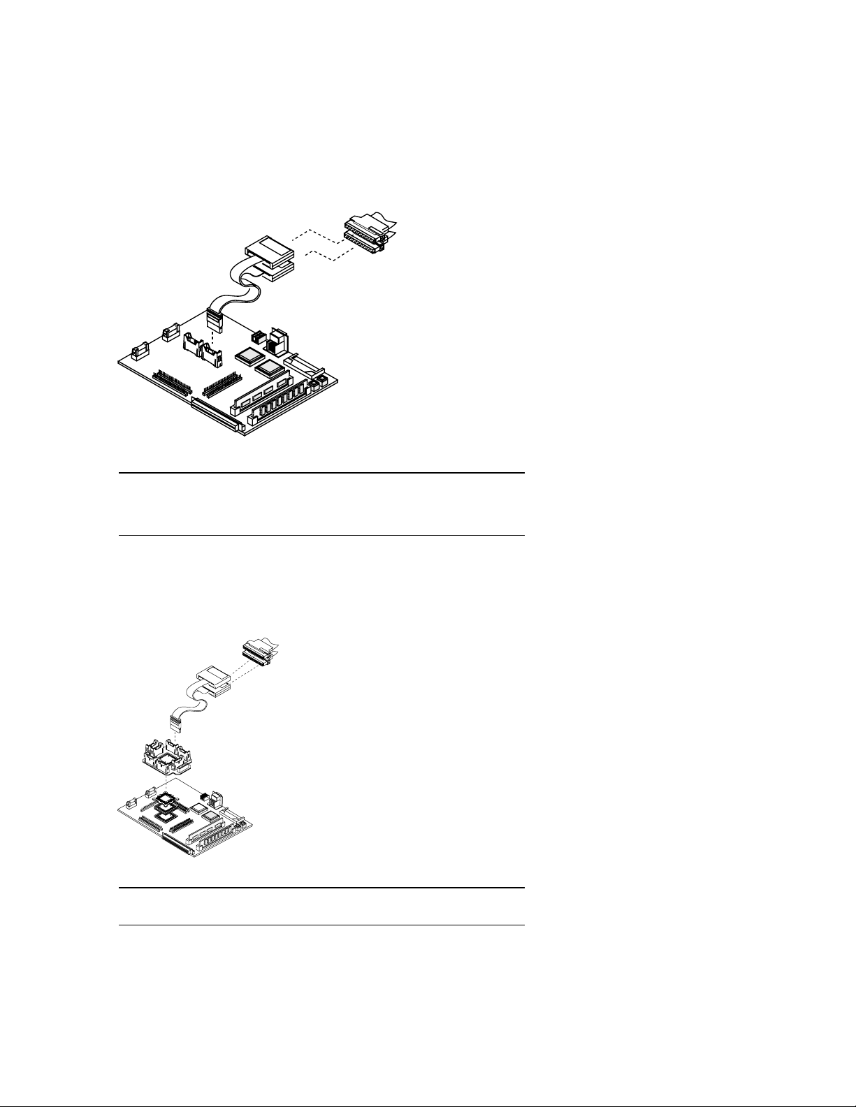
6
Selecting the Optimum Probing Strategy
For All Agilent Logic Analyzers with 40-pin Pod Connectors
Go to page 17 for a discussion of Agilent’s
target connector solutions for logic analyzers
with 40-pin pod connectors.
Designing Connectors Directly into the Target System
Refer to Processor and Bus Support for
Agilent Technologies Logic Analyzers,
publication number 5966-4365E at:
http://www.agilent.com/find/pnbs
That document will tell you what additional
probing accessories you need to connect logic
analyzers with 40-pin pod connectors to the
analysis probes.
Using Processor/Bus Specific Probes
Advantages Limitations
Very reliable connections. Requires advanced planning in the design stage.
Saves time in making multiple connections. Requires some dedicated board space.
Least amount of board space required for Moderate incremental cost.
large number of channels.
Advantages Limitations
Easiest and fastest connections to supported Moderate to significant incremental costs.
processors and buses. Only usable for the specific processor or bus.
Page 7
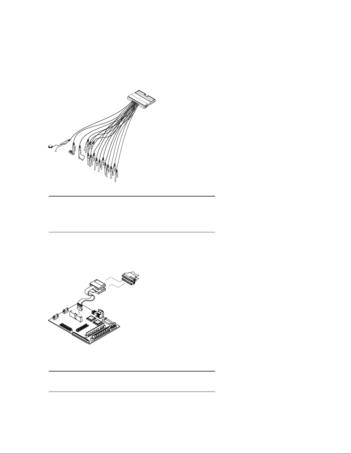
7
Selecting the Optimum Probing Strategy
For all Agilent Logic Analyzers with 90-pin Pod Connectors
Go to page 40-43 for a discussion of
Agilent’s flying lead probe sets for logic
analyzers with 90-pin pod connectors.
Connecting to Individual IC Pins, Test Points, Browsing or Solder Attach to
Components, Traces or VIAs
Advantages Limitations
Most flexible method. Time-consuming to connect large number
Convenient for picking up signals that may not of channels.
be grouped conveniently on your board with Requires more board space, for large number
buses routed to connectors of channels.
(example: system clock, interrupts). Some accessories may degrade probe
performance at high speeds.
Go to page 36 for the target connector
probing solutions for logic analyzers with
90-pin pod connectors. Go to page 32 for
connectorless solutions for logic analyzers
with 90-pin pod connectors.
Designing Connections Directly into the Target System
Advantages Limitations
Save time in making multiple connections. Requires advanced planning in the design stage.
Least amount of board space required for
large number of channels.
Page 8
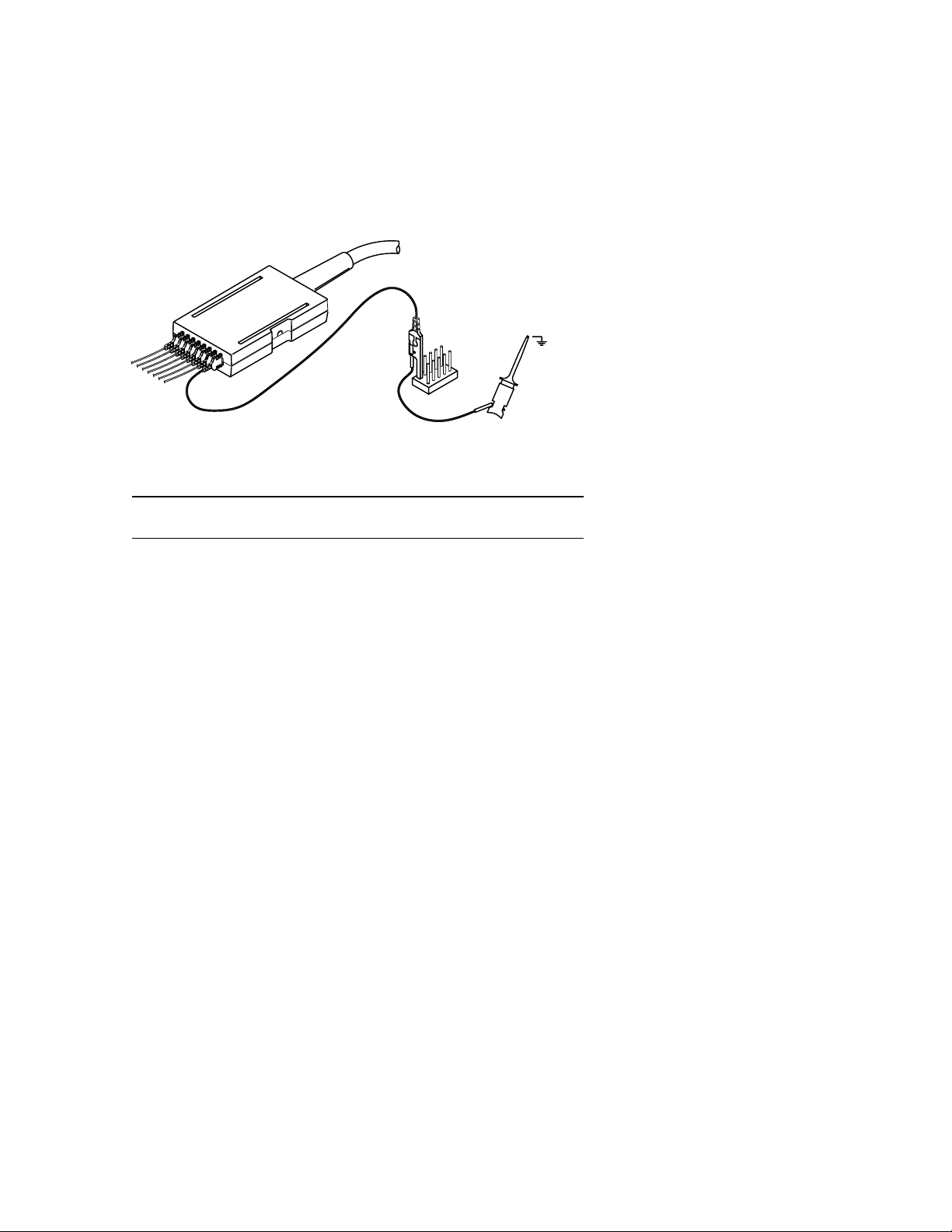
8
Selecting the Optimum Probing Strategy
For the Agilent 16517A and 16518A Logic Analysis Modules
Go to page 45 for probing solutions for the Agilent
16517A and 16518A logic analysis modules.
Connecting to Individual IC Pins or Test Points
Advantages Limitations
Very low capacitance. No high-density probing solutions available for
the 16517A and 16518A.
Page 9
9
General-Purpose Probing
For All Agilent Logic Analyzers with 40-pin Pod Connectors
When maximum signal fidelity is
required or only a few lines may
need to be probed, the 16-channel
lead sets shipped with the Agilent
logic analysis systems can
provide a quick and convenient
method for probing.
Logic Analysis
General-Purpose Probes
General-purpose probing requires
connecting probe leads to
individual signal lines. This
method is most convenient for a
small to moderate number of
signals, very flexible, and can be
used in conjunction with other
probing methods.
Note: Any probed signal line
must be able to supply a minimum
of 600 mV to the probe with the
specified loading.
The Standard Probing System
The standard probing system
consists of IC clips, probe leads,
probe housing and probe cable.
Because it is passive, the standard probing system is smaller,
lighter, and much easier to use
than active probing systems. This
passive probing system is similar
to a probing system used on a
high frequency oscilloscope. It
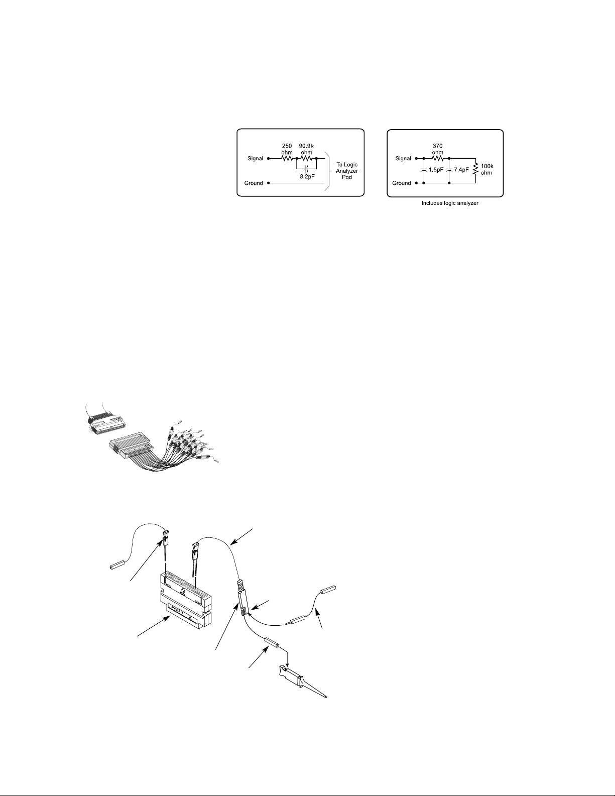
consists of an isolation network
(as shown in figure 3) at the
probe tip and a shielded resistive
transmission line. The advantages
of this system are:
• High input impedance. See
figure 3.
• Signal ground at the probe tip
for high-speed signals.
• Inexpensive, removable probe
tip assemblies.
Probe Leads and Lead Sets
Probe leads are configured into
lead sets, which can probe 16
data channels with ground, one
clock channel, and a common
ground. A 16-channel probe lead
set (part number 01650-61608) is
shown in figure 4, along with the
replacement part numbers for
individual components in figure 5.
Each probe lead is a 12-inch,
twisted-pair cable connected to
the probe cable at the probe housing (see figure 5). The probe tip
includes a signal lead, a connector for a ground lead, and the
isolation network.
The signal and ground leads can
be connected directly to the target system. This requires
installing 0.63 mm (0.025 in)
square pins, or round pins with
a diameter of between 0.66 mm
(0.026 in) and 0.84 mm (0.033 in)
directly on the board. An IC test
clip can also be used. The same
specifications apply for the pin
dimensions of the test clip.
(See figure 8 for IC test clips
available from Agilent.)
Figure 3. Probe tip Isolation network and equivalent load
Equivalent Load
Tip Isolation Network
Figure 5. Sixteen-channel probe lead set
(part number 01650-61608) replacement parts
Common ground
lead (long)
(Agilent part number
5959-9335 contains
5 pod grounds)
Probe housing
Probe lead
(Agilent part number 5959-9333
contains 5 probe leads)
Each probe lead set contains:
1 clock probe lead
16 data line leads
RC network housing
Connector for
ground lead
Signal leads
Ground leads
(Agilent part number
5959-9334 contains
5 short ground leads)
Figure 4. Sixteen-channel probe lead set
(part number 01650-61608)
Page 10
10
General-Purpose Probing
For All Agilent Logic Analyzers with 40-pin Pod Connectors
IC Clips
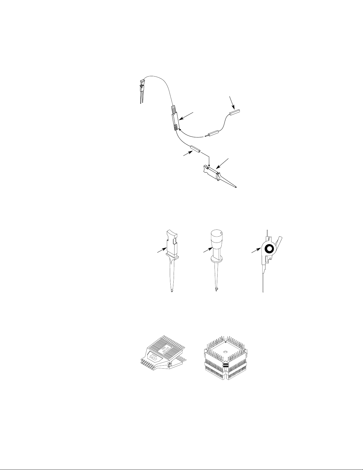
The through-hole IC clips (part
number 5959-0288, containing
20 IC clips) have a single hook
that fits around IC pins and component leads. The surface-mount
device IC clip with twin hooks
(part number 5090-4833, containing 20 IC clips) is designed for
fine surface-mounted component
leads. The twin hook 0.5 mm IC
clip (part number 10467-68701,
containing four 0.5 mm IC clips),
is very useful for 0.5 mm pitch
components. See figure 7.
The E2421A kit contains one
each: 8-pin, 14-pin, 16-pin, 20-pin,
24-pin, and 28-pin SOIC test clips.
See figure 8.
The E2422A kit contains one
each: 20-pin, 28-pin, 44-pin,
52-pin, 66-pin, and 84-pin QUAD
IC test adapters. See figure 8.
Grounding
There are three methods of
grounding the probe system.
First, the entire probe lead set
can be grounded through the
common ground. This requires
only one connection, but is not
recommended because it will
cause poor signal fidelity in
systems with fast transition
times. The recommended method
is to individually ground each
probe lead. This yields optimal
signal fidelity and is required for
signals with faster transition
times (< 4 - 5 ns).
For moderate rise times (greater
than 2 ns), it may be acceptable
to ground every other (or every
fourth) ground connection to
the target.
Figure 6. Connecting IC clips and ground leads to probes
Figure 7. SMD IC clip, through-hole IC clip and 0.5 mm IC clip
Signal leads
SMT IC clip
RC network housing
Figure 8. Typical IC test clips available in E2421A SOIC kit (left) and
E2422A QUAD kit (right)
5090-4833
5959-0288
10467-68701
Probe ground leads
Page 11

11
General-Purpose Probing
For All Agilent Logic Analyzers with 40-pin Pod Connectors
Signal Line Loading
Any probed signal line must be
able to supply a minimum of
600 mV to the probe tip while the
probe is connected to the system.
The maximum input voltage of
each probe is ±40 volts peak.
Probe Cables
The probe cable (see figure 9 and
table 1) contains 16 signal lines
and two clk lines, two +5 volt
power lines, and ground lines for
each of the signal/clock and
power lines. All of these lines are
contained in a 4.5-foot cable. The
probe cable is included with the
logic analyzer. The cable grounds
are chassis (earth) grounds, not
“floating” grounds. The two
+5 volt power lines can be used
to power active probing systems.
Consult the specifications for the
individual logic analyzers or logic
analyzer cards for the maximum
allowable current through each
+5 volt power supply.
Caution: These +5 volt power
lines MUST NOT be connected to
the target’s power supply.
Caution: Be careful when using
straight wire probe leads, one
common ground, or RC networks
located far from the target.
These circumstances increase
the impact of analog effects
such as crosstalk and EMT
susceptibility, which contribute
to measurement errors.
Logic Analyzer 01660-61605 16555-61606 16710-61603 16715-61601
Stand Alone or Module
16550A x
16554A x
16555A/D x
16556A/D x
16557D x
16710A x
16711A x
16712A x
16715A x
16716A x
16717A x
16718A x
16719A x
16740/41/42A x
16750B x
16751B x
16752B x
16706 Series x
1680 Series x
1690 Series x
Figure 9. Logic analyzer probe cable
Page 12
12
General-Purpose Probing
Wedge Adapters
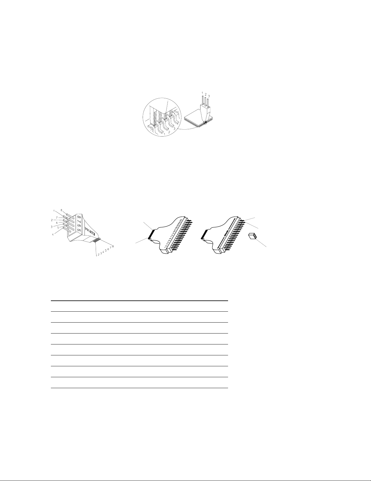
The Agilent Technologies Wedge
technology provides very reliable
probing of a few channels on
0.5 mm and 0.65 mm pitch QFPs.
No clear area is required around
the device. Each Wedge of the
probe slides between the legs of
the QFP. The side of each Wedge
probe contacts the package legs.
An insulation core electrically
isolates the sides of each Wedge
(see figures 10 and 11). Various
3-signal, 8-signal, and 16-signal
probes are available (see table 2).
IC Leg Spacing Number of Signals Number of Wedges in Pack Model Number
0.5 mm 3 1 E2613A
0.5 mm 3 2 E2613B
0.5 mm 8 1 E2614A
0.5 mm 16 1 E2643A
0.65 mm 3 1 E2615A
0.65 mm 3 2 E2615B
0.65 mm 8 1 E2616A
0.65 mm 16 1 E2644A
Table 2. Wedge probe adapter
Figure 10. Three-signal Wedge
electrical connection
Figure 11. Eight-signal and 16-signal Wedge (16-signal Wedge has a common ground plane)
Top view of 16 signal pins
Bottom view of 16 ground pins (connected to common ground plane)
Ground connector pins
Wedge connector pins
Removable jumper
1
Gaps
16
Page 13
13
General-Purpose Probing
Miscellaneous Probing Accessories
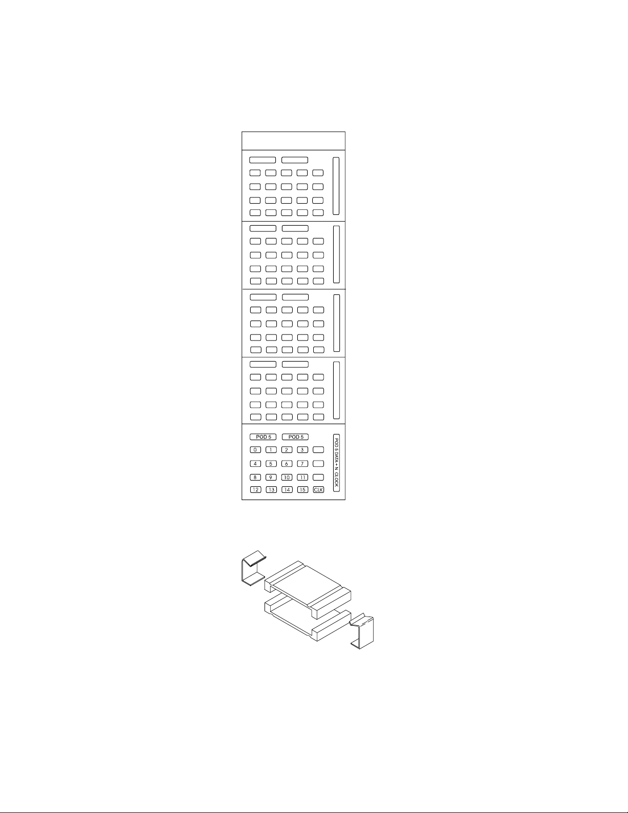
Additional labels can be ordered
to mark test systems for specific
applications. The ferrite core
assembly can be added to the
probe cable to suppress EMI
and RFI noise that can corrupt
the measurement.
Figure 12. Labels, 01650-94303
Figure 13. Ferrite core assembly, 16555-60001
PROBE & CABLE NUMBERING LABELS
HP PART NUMBER 01650-94303 MADE IN U.S.A.
POD 1 POD 1
1
POD 2
POD 3
8
POD 4
8
2
3
6
54
9
1
54
9
1
54
1
54
7
1110
141312
15
CLK
POD 2
2
3
6
7
1110
141312
15
CLK
POD 3
2
3
6
7
9
1110
1413
15
POD 4
2
3
6
7
9
1110
141312
15
CLK
0
8
0
8
0
12 CLK
0
POD 1 DATA + J CLOCK
POD 2 DATA + K CLOCK
POD 3 DATA + L CLOCK
POD 4 DATA + M CLOCK
Page 14
14
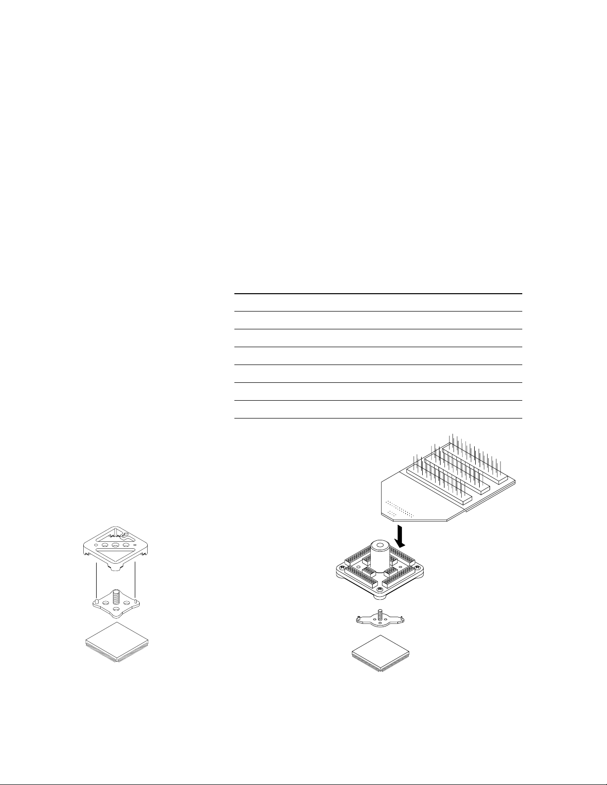
Figure 15. Elastomeric probing solution
1/4 flex adapter
(4 required to connect all pins)
Elastomeric
probe adapter
Retainer
TQFP IC
QFP Package Probing
Figure 14. Locator tool aligning
retainer on the device
Locator tool
Retainer
TQFP IC
to the pins on its respective side
of the QFP device. Additional
retainers and locator tools are
also available. A kit of five
retainers and adhesive is available as option #201. The locator
tool is option #202. These option
numbers apply to any of the listed elastomeric probe adapter
model numbers, for example,
Agilent E5374A #202.
Package Pin Pitch Elastomeric Probe Adapter 1/4 Flex Adapter
144-pin TQFP 0.5 mm E5336A E5340A
144-pin PQFP/CQFP 0.65 mm E5361A E5340A
160-pin PQFP/CQFP 0.65 mm E5373A E5349A
160-pin TQFP 0.5 mm E5377A E5349A
176-pin TQFP 0.5 mm E5348A E5349A
208-pin PQFP/CQFP 0.5 mm E5374A E5371A
240-pin PQFP/CQFP 0.5 mm E5363A E5371A
Table 3. Elastomeric probe adapters
If your target contains ASICs,
FPGAs, or other devices in an
industry-standard QFP configuration, Agilent Technologies has a
series of elastomeric probes from
which you can choose. Agilent’s
state-of-the-art elastomeric
probing technology offers an
inexpensive, convenient, and
reliable solution for 0.5 mm
and 0.65 mm high-density
TQFP/CQFP/PQFP packages.
The elastomer material on the
probe makes contact between the
probe and the pins of a device.
Embedded on the surface of the
elastomer are redundant connections for each pin, which ensure a
reliable and rugged connection.
A locator tool, included with the
probe adapter, correctly aligns
the retainer to the device. A
small amount of adhesive on the
bottom of the retainer holds the
retainer firmly to the device.
After the adhesive is set, the locator tool can be removed. The
elastomeric probe adapter then
attaches to the device, held in
place by the retainer and its
knurled nut. Five retainers, a
locator tool, and adhesive are
included with each elastomeric
probe adapter.
Additional Accessories
Quarter flex adapters, shown in
figure 15, are available to bring
the signals from the elastomeric
probe adapter to general-purpose
headers for easy connection to
logic analyzers, oscilloscopes, or
other test equipment. Four 1/4
flex adapters are required to view
all signals on a device. Each 1/4
flex adapter provides connections
Page 15

15
QFP Package Probing
Electrical characteristics for this
probing technology are listed in
table 4.
Note: The Agilent logic analyzer
probes are connected to the
adapters shown in this section.
The target system impedance load
is increased slightly (see table 4).
Fast transition times (< 2 - 3 ns)
may suffer some loss of signal
fidelity.
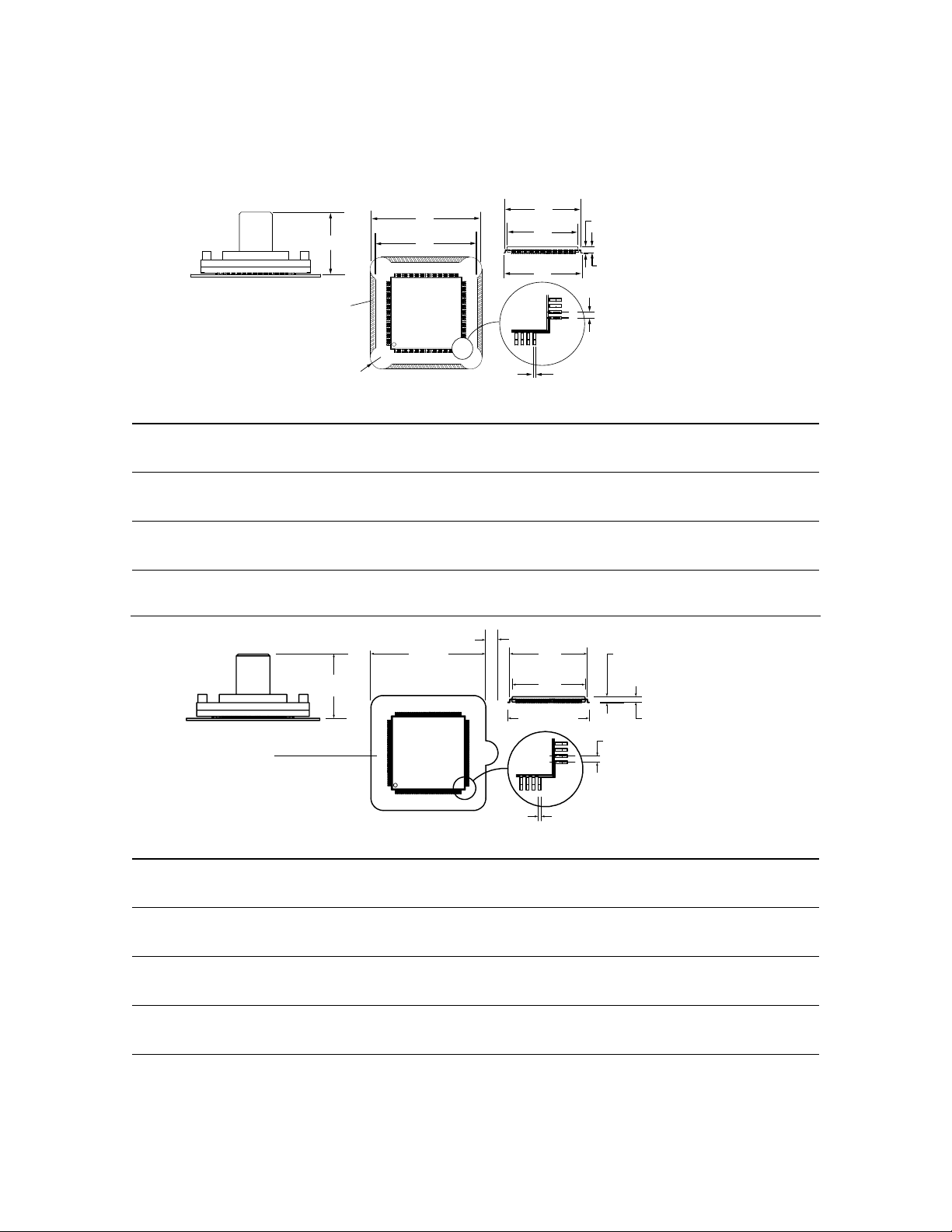
The probe adapters require a
minimal “keep out” area around
the device, as shown in the
dimension tables of figures 16
and 17.
Electrical Characteristics Elastomeric Probe Adapter 1/4 Flex Adapter
Operating voltage <40 V (DC + peak AC) <40 V (DC + peak AC)
Operating current 0.5A (max) 0.5A (max)
Insulation resistance >100 MΩ >100 MΩ
Model Parameters
Pin-to-ground plane
capacitance (typical)
E5340A
3.0 pF first row
4.0 pF second row
6.0 pF third row
E5349A
2.5 pF first row
3.5 pF second row
5.0 pF third row
E5371A
2.5 pF first row
3.5 pF second row
5.0 pF third row
Pin-to-pin capacitance 0.5 pF 2 pF
Self inductance (typical)
E5340A
15 nH first row
25 nH second row
35 nH third row
E5349A
20 nH first row
30 nH second row
40 nH third row
E5371A
20 nH first row
30 nH second row
40 nH third row
Environmental Characteristics
Operating temperature 0°C to 50°C 0°C to 50°C
Maximum operating humidity 75% relative humidity 75% relative humidity
Table 4. Probe and flexible adapter electrical and environmental characteristics
Page 16
16
QFP Package Probing
Adapter A B C D E F G H J K L M
144-Pin TQFP
(inches) 0.674 1.240 1.130 0.055 0.138 0.827 (min) 0.795 (max) 0.866±0.008 0.057 to 0.063 0.053 to 0.057 0.0197±0.0012 0.009±0.002
(millimeters) 17.13 31.50 28.70 1.40 3.50 21.00 (min) 20.20 (max) 22.00±0.20 1.450 to 1.60 1.350 to 1.45 0.500±0.03 0.220±0.05
160-Pin TQFP
(inches) 0.76 1.343 1.343 0 0.11 0.988 (min) 0.953 (max) 1.024±0.008 0.061 to 0.063 0.051 to 0.059 0.01965±0.001 0.0087 to 0.015
(millimeters) 19.2 34.11 34.11 0 2.79 25.09 (min) 24.20 (max) 26.00±0.20 1.550 to 1.61 1.3 to 1.5 0.50±0.03 0.220 to 0.38
176-Pin TQFP
(inches) 0.674 1.398 1.287 0.055 0.138 0.984 (min) 0.953 (max) 1.024±0.008 0.057 to 0.063 0.053 to 0.057 0.0197±0.0012 0.009±0.002
(millimeters) 17.13 35.50 32.70 1.40 3.50 25.00 (min) 24.20 (max) 26.00±0.20 1.450 to 1.60 1.350 to 1.45 0.50±0.03 0.220±0.05
Figure 16. Elastomeric probe and package dimensions for TQFP
A
E
Maximum height of components in this area
B
C
F
G
H
K
J
L
M
Adapter A B C E F G H J K L M
144-Pin PQFP/CQFP
(inches) 0.73 1.583 0.16 0.01 1.135 (min) 1.106 (max) 1.236 (max) 0.094 to 0.098 0.108 (max) .0256±0.0012 0.009±0.002
(millimeters) 18.5 40.21 4 0.3 28.85 (min) 28.10 (max) 31.40 (max) 2.40 to 2.50 2.75 (max) 0.65±.03 0.22±0.05
160-Pin PQFP/CQFP
(inches) 0.76 1.583 0.16 0.03 1.154 (min) 1.106 (max) 1.266 (max) 0.126 to 0.146 0.136 to 0.161 .0256±0.0012 0.009±0.002
(millimeters) 19.2 40.21 4 0.8 29.32 (min) 28.10 (max) 32.15 (max) 3.20 to 3.70 3.45 to 4.10 0.65±.03 0.22±0.05
208-Pin PQFP/CQFP
(inches) 0.76 1.583 0.16 0.03 1.136 (min) 1.110 (max) 1.197 to 1.213 0.126 to 0.142 0.136 to 0.161 0.0197±0.0012 0.009±0.002
(millimeters) 19.2 40.21 4 0.8 28.85 (min) 28.20 (max) 30.40 to 30.80 3.20 to 3.60 3.45 to 3.60 0.50±0.03 0.22±0.05
240-Pin PQFP/CQFP
(inches) 0.76 1.937 0.16 0.03 1.293 (min) 1.268 (max) 1.354 to 1.370 0.126 to 0.142 0.136 to 0.161 0.0197±0.0012 0.009±0.002
(millimeters) 19.2 49.20 4 0.8 32.85 (min) 32.20 (max) 34.40 to 34.80 3.20 to 3.60 3.45 to 3.60 0.50±0.03 0.22±0.05
Figure 17. Elastomeric probe and package dimensions for PQFP/CQFP
Maximum height of components in this area
A
B
C
D
E
F
G
H
K
J
L (non-accumulative)
M
Page 17

17
Designing and Probing with Target Connections
Normal-Density, Medium-Performance Applications
In some cases, you may not have
a standard QFP package on the
target available for probing
access, or your device may be
available only in BGA packaging.
Agilent recommends that targets
with probing constraints have
connectors designed into the
prototype versions of the product
for effective hardware and software debug. The following should
be considered when designing
with connectors:
• Select the appropriate connector technology for your target
speed and target density.
• Carefully select all lines for
routing to the connectors that
may be needed for debug.
• Group the lines at each
connector for your probing
convenience. For example,
Agilent may have written an
inverse assembler for your
device that has a preconfigured signal order. Before
designing, refer to the documentation for this inverse
assembler for essential signal
lines and order.
• Keep the routing to connectors
as short as possible to minimize target impact and provide
accurate data.
• Examine the impact of probing
isolation networks designed
into the target vs. the isolation
network products offered by
Agilent Technologies.
An isolation network must be
located between the target and
the logic analyzer. It can be
located on the target board in
through-hole or SMT parts; or
it can be attached to the logic
analyzer cable with the probe
leads (the isolation network is
molded into the end of the probe);
or the Agilent 01650-63203 isolation adapter with self contained
isolation networks can be used.
Probe leads can be used with
connectors but are not the most
convenient method. Direct connection of the connectors with
the analyzer cable (isolation network parts on the target) or with
a probe or isolation adapter is the
faster, more convenient method.
Page 18
18
Designing and Probing with Target Connections
For All Agilent Logic Analyzers with 40-pin Pod Connectors
Low Density, Moderate Performance
Solutions shown in the
“High-Density, High-Performance”
(page 23) section of this document can be used in place of the
solutions described here. Agilent
recommends standard 0.1 inch
center connectors for normal
density applications if the loading/speed is not a significant
issue. Many of these items are
available from 3M or Agilent
(see table 5). See the “Related
Information” section at the
end of this document for 3M
address information.
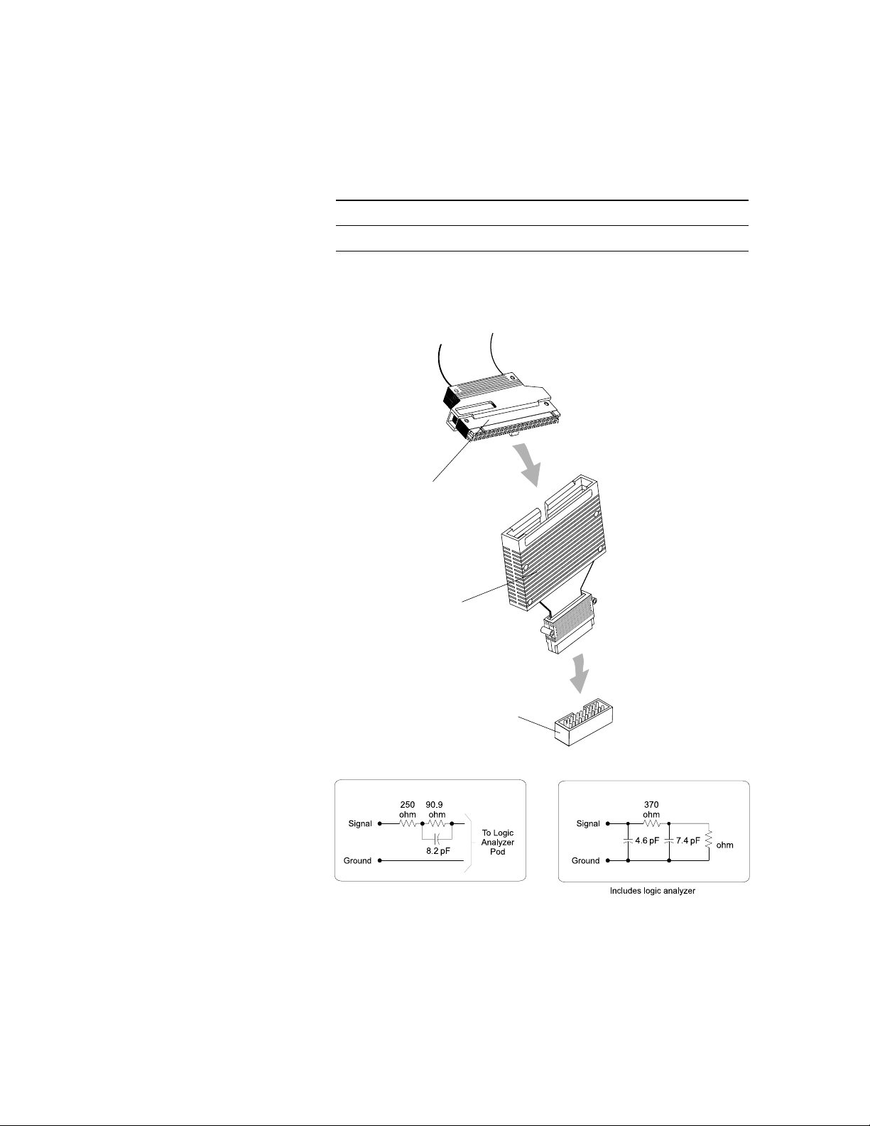
Direct Connection through
Isolation Adapter
Isolation adapters (Agilent part
number 01650-63203) that connect to the end of the probe cable
are designed to perform two functions. The first is to reduce the
number of pins required for the
header on the target board from
40 pins to 20 pins. This process
reduces the board area dedicated
to the probing connection. The
second function is to provide the
proper RC networks in a very
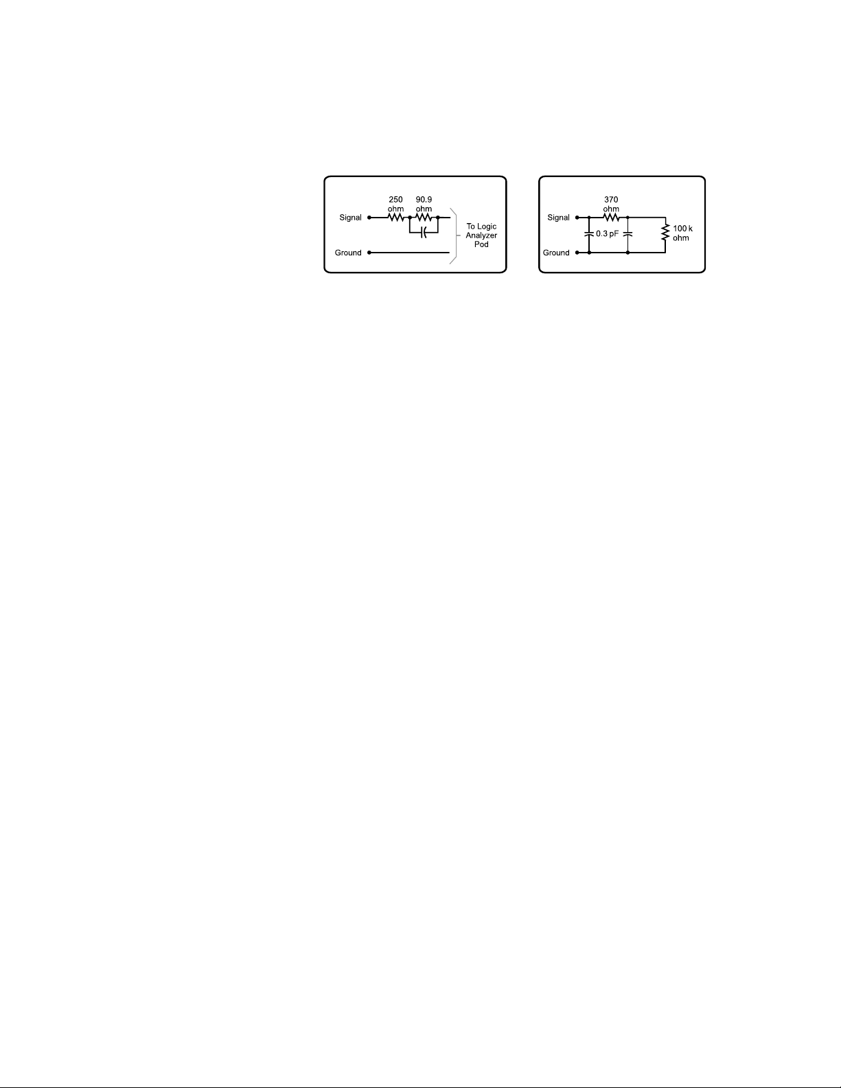
convenient package. Figure 18
illustrates how the isolation
adapter physically connects to
the target system and the equivalent load of the isolation adapter
connected to an Agilent
Technologies logic analyzer.
Figures 19 and 20 show the
pinout diagrams for the probe
cable and the isolation adapter,
respectively. There are two
20-pin connectors, along with
their Agilent Technologies and
3M part numbers, listed in table 5.
Note: The Agilent 01650-63203
saves space by using a common
ground (see figure 20). This will
impact signal fidelity, especially
faster transition times (< 4 - 5 ns).
Agilent Part Number 3M Part Number Connector Description
1251-8106 2520-6002 20-Pin, low-profile (straight)
1251-8473 2520-5002 20-Pin, low-profile (right-angle)
Table 5. Twenty-pin connectors for fixed configuration probing.
(Requires isolation adapter)
Logic analyzer pod cable
Isolation Adapter
(Agilent 01650-63203)
20-pin connector
(Agilent 1251-8106)
Figure 18. Isolation adapter (01650-63203) and equivalent load
Isolation Adapter RC Network
k
Equivalent Load
100 k
Page 19
19
Designing and Probing with Target Connections
For All Agilent Logic Analyzers with 40-pin Pod Connectors
Figure 20. Pinout for 100 kΩ isolation adapter (Agilent part number 01650-63203)
Figure 19. Pinout for probe cable
Note: +5V is supplied from the
logic analyzer to provide power
for analysis probes and demo
boards. DO NOT connect these
pins to a +5V supply in the
target system!
POWER GND 2
SIGNAL GND 4
SIGNAL GND 6
SIGNAL GND 8
SIGNAL GND 10
SIGNAL GND 12
SIGNAL GND 14
SIGNAL GND 16
SIGNAL GND 18
SIGNAL GND 20
SIGNAL GND 22
SIGNAL GND 24
SIGNAL GND 26
SIGNAL GND 28
SIGNAL GND 30
SIGNAL GND 32
SIGNAL GND 34
SIGNAL GND 36
SIGNAL GND 38
POWER GND 40
1 +5V (see note)
3 CLOCK
5 Do not connect
7 D15
9 D14
11 D13
13 D12
15 D11
17 D10
19 D9
21 D8
23 D7
25 D6
27 D5
29 D4
31 D3
33 D2
35 D1
37 D0
39 +5V
Do not connect 2
D15 4
D13 6
GND 20
D11 8
D9 10
D7 12
D5 14
D3 16
D1 18
1 +5V (see note)
3 CLOCK
5 D14
7 D12
9 D10
11 D8
13 D6
15 D4
17 D2
19 D0
Page 20
20
Designing and Probing with Target Connections
For All Agilent Logic Analyzers with 40-pin Pod Connectors
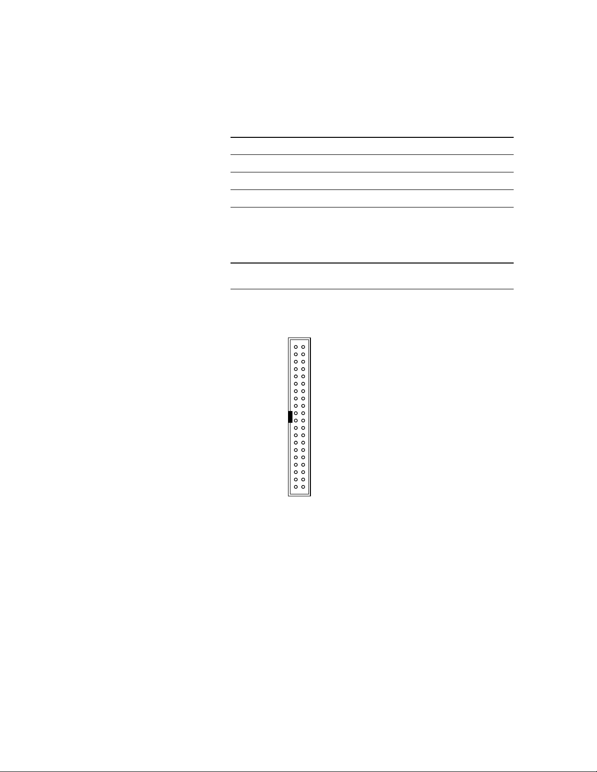
Direct Connection through 40-Pin
Connectors
The probe cable also can be
plugged directly into the various
40-pin connectors shown in table
6, but proper isolation networks
must be installed directly onto
the target system board (see
figure 21 for the 40-pin connector
pinout).
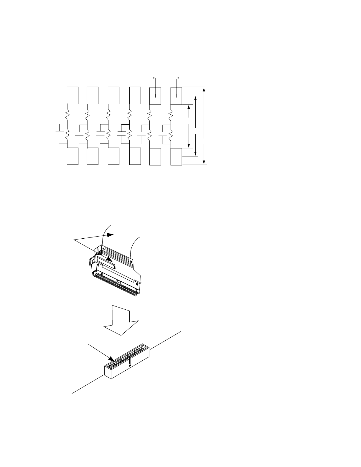
Agilent Technologies offers a
12-pin SMT (Agilent part number
5062-7396), which provides six
isolation networks, as shown in
figure 22. Three of these SMTs
are required for each probe cable.
Discrete components can also be
used for the proper isolation
network. See figure 24 for an
equivalent load diagram for the
isolation networks.
Note that the effective input
capacitive lead of an isolation
network using discrete components is a function of the layout
geometry and the parasitic
capacitance of the input series
damping resistor.
Agilent Part Number 3M Part Number Connector Description
1251-8828C 2540-6002 40-Pin, low-profile (straight)
1251-8158 2540-5002 40-Pin, low-profile (right-angle)
1251-8831 3432-6302 40-Pin, with long latches (straight)
1251-8931 3432-5302 40-Pin, with long latches (right-angle)
Table 6. Forty-pin connectors for fixed configuration probing.
(Requires isolation network installed on target board)
Agilent Part Number Package Type
5062-7396 SMT, 12-pin, provides 6 isolation networks (3 SMTs required
for each probe cable)
Table 7. Available isolation networks
Figure 21. Forty-pin connector pinout
Note: +5V is supplied from the
logic analyzer to provide power
for analysis probes and demo
boards. DO NOT connect these
pins to a +5V supply in the
target system!
+5V (see note) 1
CLOCK 3
Do not connect 5
D15 7
D14 9
D13 11
D12 13
D11 15
D10 17
D9 19
D8 21
D7 23
D6 25
D5 27
D4 29
D3 31
D2 33
D1 35
D0 37
+5V 39
2 POWER GND
4 SIGNAL GND
6 SIGNAL GND
8 SIGNAL GND
10 SIGNAL GND
12 SIGNAL GND
14 SIGNAL GND
16 SIGNAL GND
18 SIGNAL GND
20 SIGNAL GND
22 SIGNAL GND
24 SIGNAL GND
26 SIGNAL GND
28 SIGNAL GND
30 SIGNAL GND
32 SIGNAL GND
34 SIGNAL GND
36 SIGNAL GND
38 SIGNAL GND
40 POWER GND
Page 21
21
Designing and Probing with Target Connections
For All Agilent Logic Analyzers with 40-pin Pod Connectors
Figure 23. Connecting probe cable to 40-pin connector with isolation networks
Probe cable
(from logic
analyzer)
40-pin connector
(Agilent part number 1251-8828C)
2 x 20-pin male connector with
0.1” x 0.1” spacing
Logic Analyzer Pod
Pad Dimension = 0.030” x 0.040”
7
5
8
910
3
11
2
1
12
0.050”
0.080”
0.120”
0.160”
R1
C1
R2
R3
R4
R5
R6
R7
C2
R8
C3
R9
C4
R10
C5
R11
C6
R12
Notes:
4
6
1. Resistances:
R1 through R6: 250 Ω
R7 through R12: 90.9 kΩ
2. Capacitance 8.2 pF
Figure 22. Recommended PC board pattern for 5062-7396 surface mount isolation network
Page 22
22
Designing and Probing with Target Connections
For All Agilent Logic Analyzers with 40-pin Pod Connectors
Notes on Using Discrete Components
Discrete components can be used
to design the isolation network.
Agilent Technologies recommends
the circuit shown in figure 24.
To achieve the equivalent load
shown in the figure, trace lengths
should be minimized by locating
the RC network very near the
measured node. Actual load will
be the stub length load added to
the equivalent load in the figure.
Trace length from the suggested
on-board RC network to the
target connector must be 3 to
4 inches or less. This transmission line should be designed for
an impedance in the range of 80
to 100 ohms (closer to 100 ohms
is better).
Figure 24. Equivalent load for on-target discrete components.
Also applies to SMT (5062-7396) RC networks.
Equivalent LoadSuggested On Board Isolation Network
Includes on board isolation network and
logic analyzer
k
8.2 pF
7.4 pF
Page 23
23
Designing and Probing with Target Connections
For All Agilent Logic Analyzers with 40-pin Pod Connectors
High Density, High Performance
Agilent Technologies has
developed high-density probing
solutions based on the 100-pin
Samtec and AMP Mictor 38-pin
connectors. The Agilent probes
and adapter cables, E5346A,
E5339A, E5351A, and E5385A
provide a connection strategy to
route your important signals to
the Agilent logic analyzer. Simply
design the connectors onto the
board for the critical signals such
as address, data, and status bits.
The connectors consume a
minimal amount of board space.
Each connector provides 32
channels of logic analysis per
connector with two clocks.
Connectors can be purchased
directly from AMP, Samtec, or
Agilent Technologies. See the
“Related Information” at the end
of this document.
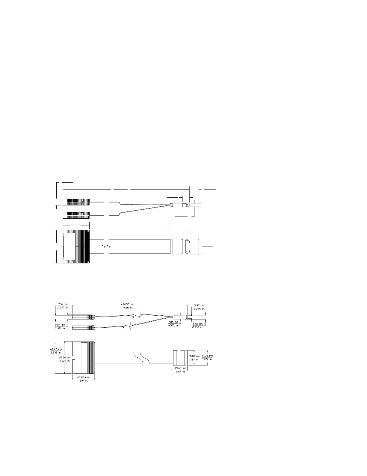
Figure 25. E5346A, E5351A, E5339A mechanical dimensions
Figure 26. E5385A 100-pin probe mechanical dimensions
2.393 in
60.77 mm
0.450 in
11.44 mm
1.64 in
41.6 mm
17.500 in
444.50 mm
0.465 in
11.80 mm
35.56 mm
0.271 in
6.89 mm
1.400 in
0.209 in
5.31 mm
1.100 in
27.94 mm
Page 24
24
Designing and Probing with Target Connections
For All Agilent Logic Analyzers with 40-pin Pod Connectors
Agilent Technologies
E5346A, E5339A, and E5385A Probes
The E5346A, E5339A, and
E5385A probes include the
required isolation networks for
the logic analyzer right at the
probe tip, close to the target.
The E5346A and E5385A are
designed to acquire signals with
peak-to-peak amplitude as low as
500 mV. The E5339A is designed
to acquire signals as small as
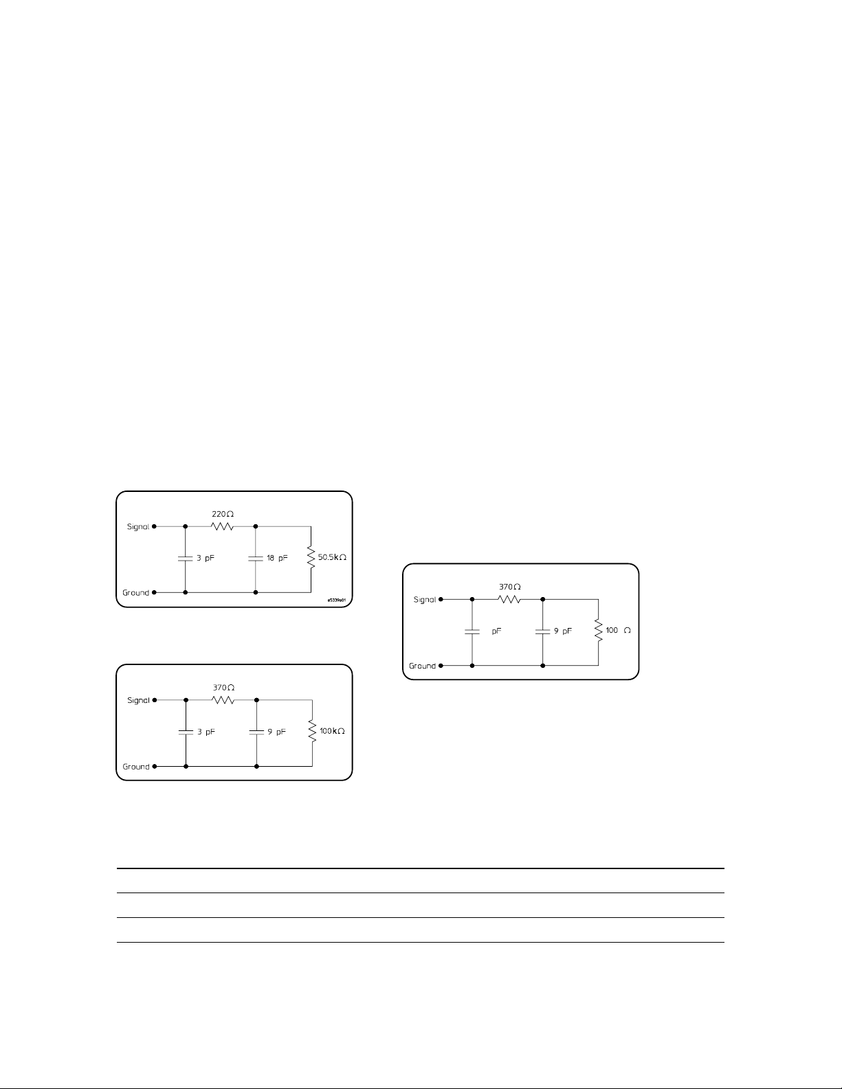
250 mV peak-to-peak. Figure 27
shows the equivalent load for the
E5339A, and figure 28 shows the
equivalent load for the E5346A.
Figure 29 shows the equivalent
load for the E5385A.
To use the E5346A, E5339A, or
E5385A at high clock speeds, the
following design guidelines
should be observed:
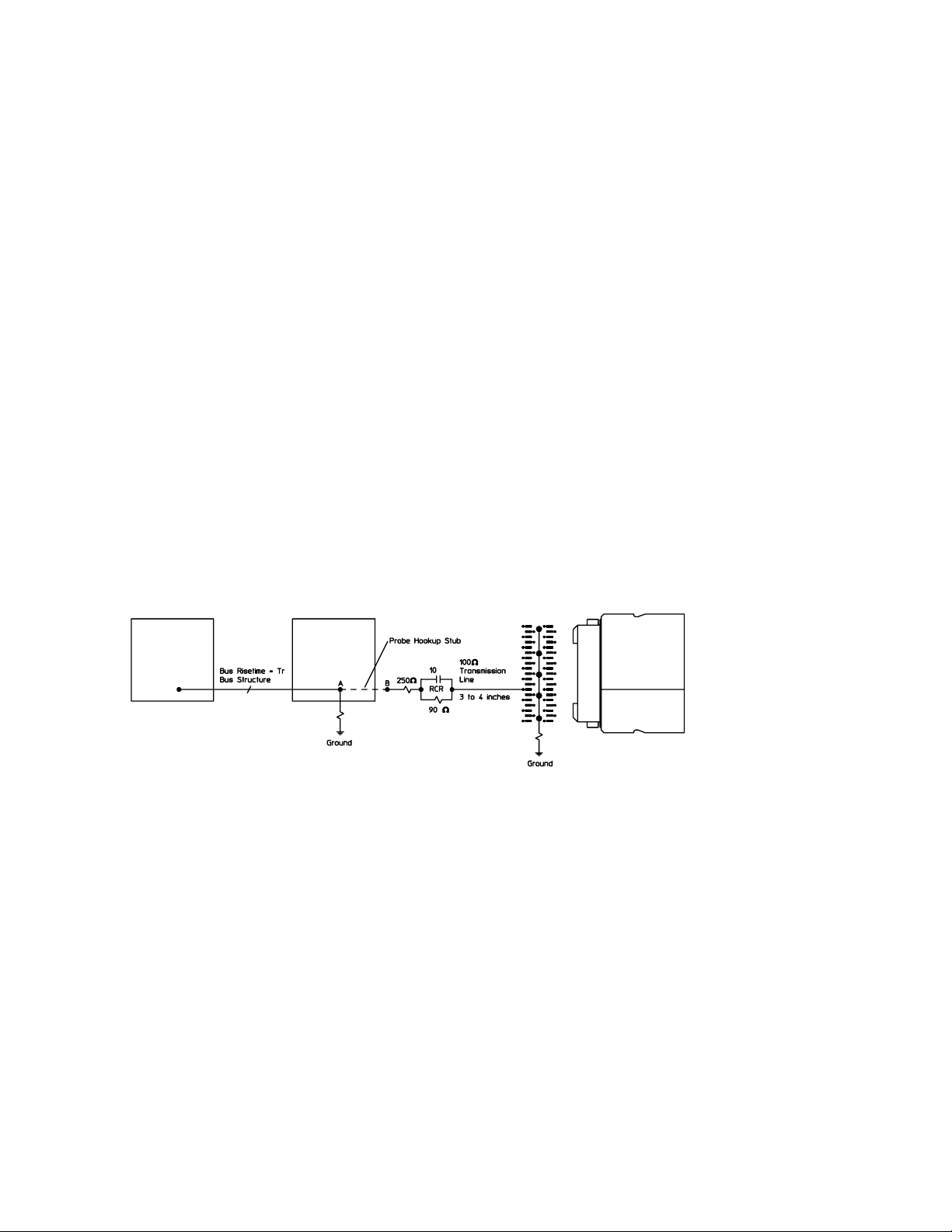
• Calculate the electrical length
of the probe hookup stub.
• For PC board material with
E
r
=4.9, use a propagation delay
of 160 ps/inch.
• Check that the propagation
delay of the probe hookup stub
is less than 20% of the bus signal risetime (T
r
). If it is, the
E5346A, E5339A, or E5385A
can be used for connection.
For example, if Er=4.9, a 2.5 inch
probe hookup stub generates a
propagation delay of 400 ps.
If T
r
is > 2 ns, the E5346A,
E5339A, or E5385A is a viable
probing choice.
The E5346A and E5339A use the
AMP Mictor 38-pin connector.
The E5385A uses a 100-pin
connector manufactured by
Samtec. Agilent recommends the
E5385A for new applications, due
to the reduced input capacitive
loading and improved isolation
between adjacent channels.
For additional information on designing connectors into a target system, refer to the following documents:
Agilent Technologies E5346A/E5351A Probe/Adapter Cable Installation Note E5346-92014 http://literature.agilent.com/litweb/pdf/E5346-92014.pdf
Agilent Technologies E5339A Low Voltage Probe Installation Note E5339-92002 http://literature.agilent.com/litweb/pdf/E5339-92002.pdf
Agilent Technologies E5385A Probe Installation Note E5385-92001 http://literature.agilent.com/litweb/pdf/E5385-92001.pdf
Figure 28. E5346A input equivalent load
Figure 27. E5339A input equivalent load
Equivalent Load
Equivalent Load
k
1.5
Figure 29. E5385A input equivalent load
Equivalent Load
Page 25

25
Designing and Probing with Target Connections
For All Agilent Logic Analyzers with 40-pin Pod Connectors
Figure 30. Agilent E5339A, E5346A, and E5351A connection and pinout
Logic analyzer pod
Optional shroud (recommended)
See table 8 on page 29
Amp “Mictor 38” connector
(AMP 2-767004-2),
Agilent part number 1252-7431
Figure 31. Agilent E5339A, E5346A, and E5385A design rules
connector
38-pin Probe
(Agilent E5339A, E5346A, E5351A)
E5339A,
E5346A,
or E5385A
Probe
Page 26
26
Designing and Probing with Target Connections
For All Agilent Logic Analyzers with 40-pin Pod Connectors
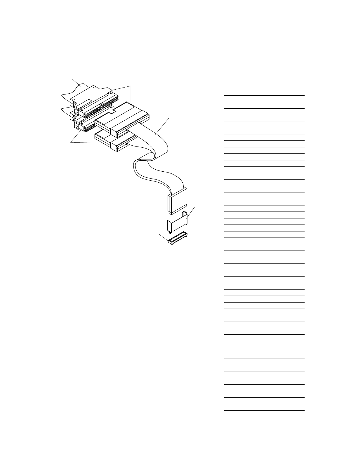
100-pin connector
Agilent part number 1253-7620
Samtec part number ASP-65067-01
Probe cables from
logic analyzer
Figure 32. Agilent E5385A connection and pinout
Odd # probes
E5385A 100-pin probe
Even #
probes
Shroud
See table 8
on page 29
for part
number
E5385A 100-Pin Probe Pin Assignments
Signal Pin Number Signal
Ground 1 2 Ground
Do Not Connect 3 4 Do Not Connect
Ground 5 6 Ground
Odd D0 7 8 Even D0
Ground 9 10 Ground
Odd D1 11 12 Even D1
Ground 13 14 Ground
Odd D2 15 16 Even D2
Ground 17 18 Ground
Odd D3 19 20 Even D3
Ground 21 22 Ground
Odd D4 23 24 Even D4
Ground 25 26 Ground
Odd D5 27 28 Even D5
Ground 29 30 Ground
Odd D6 31 32 Even D6
Ground 33 34 Ground
Odd D7 35 36 Even D7
Ground 37 38 Ground
Odd D8 39 40 Even D8
Ground 41 42 Ground
Odd D9 43 44 Even D9
Ground 45 46 Ground
Odd D10 47 48 Even D10
Ground 49 50 Ground
Odd D11 51 52 Even D11
Ground 53 54 Ground
Odd D12 55 56 Even D12
Ground 57 58 Ground
Odd D13 59 60 Even D13
Ground 61 62 Ground
Odd D14 63 64 Even D14
Ground 65 66 Ground
Odd D15 67 68 Even D15
Ground 69 70 Ground
NC 71 72 NC
Ground 73 74 Ground
NC 75 76 NC
Ground 77 78 Ground
Odd D16P/ 79 80 Even D16P/
Odd CLK Even CLK
Ground 81 82 Ground
NC 83 84 NC
Ground 85 86 Ground
NC 87 88 NC
Ground 89 90 Ground
NC 91 92 NC
Ground 93 94 Ground
Ground 95 96 Ground
+5v 97 98 +5v
+5v 99 100 +5v
Page 27
27
Designing and Probing with Target Connections
For All Agilent Logic Analyzers with 40-pin Pod Connectors
Agilent Technologies E5351A
38-Pin Adapter Cable
If the calculated electrical
length of the required routing
stub prohibits the use of the
Agilent E5339A, E5346A, or
E5385A, the Agilent E5351A
can be used with the required
isolation networks installed on
the target.
The E5351A does not have its
own internal isolation networks.
When using the E5351A, place
the SIP isolation networks,
surface mount isolation network
5062-7396, or equivalent discrete
components very near the target
component for measurement.
Ensure that the stub length
between the target component
and the isolation network is
short. The stub propagation
delay should be less than 20%
of the bus signal rise time, as
mentioned before. The transmission line from the on-board
isolation network to the Mictor
connector should be designed for
an impedance in the range of 80
to 100 ohms (closer to 100 ohms
is better). This length should not
exceed 3 to 4 inches, and all
signal line lengths should be
equal. Signal line length variation
should not cause propagation
delay variation to exceed 20 ps
between signal lines.
Figure 33. Agilent Technologies E5351A design rules
Notes on Using Discrete Components
Discrete components can be used
in the design of the RC network.
Agilent Technologies recommends
the circuit shown in figure 24. To
achieve the equivalent load shown
in the figure, trace lengths should
be minimized by locating the RC
network very near the measured
node. Actual load will be the stub
length load added to the equivalent load in the figure.
F
p
k
E5351A Probe
Page 28
28
Designing and Probing with Target Connections
For All Agilent Logic Analyzers with 40-pin Pod Connectors
Options for On-Board Terminations
for the E5351A
There are two options for
isolating the E5351A on the
target PC board:
• Use the surface mount isolation network, Agilent part
number 5062-7396. Refer
to figure 35 for schematic
and pinout.
• Use discrete components.
Refer to figure 34 for recommended components and
equivalent load.
If you are operating at state
speeds above 200 MHz, you
should use discrete components
for best results. Due to the added
electrical length of the E5351A
probe cable, the divider compensating capacitors in the SIP, and
surface-mount isolation networks
are not optimum for the E5351A,
but they are usable up to 200 MHz
clock rates.
Notes on Using the 5062-7396
SMT Part
Agilent currently recommends a
two-step process in soldering the
SMT part to the board. The first
pass places solder paste on those
pads with vias. Application of
heat allows the via to fill with
solder. (If only one solder step is
used, the solder wicks away from
the part into the via and a solid
connection will not be made with
the part.) The next pass places
solder paste on all of the pads.
As shown in figure 35, the
5062-7396 SMT isolation network
supports six logic analysis
channels. The size of the part
allows you to repeat the pattern
in figure 35 to accommodate multiple parts stacked end-to-end for
the number of channels needed in
your application. Three of these
SMTs are required for each probe
Suggested On Board Isolation Network Equivalent Load
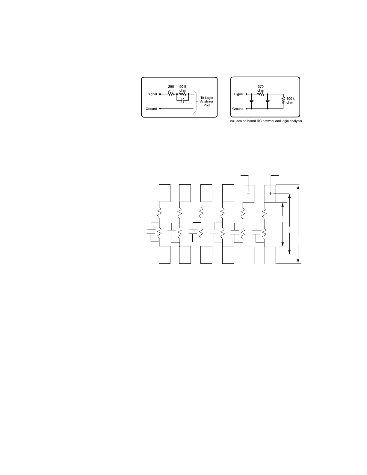
Note 1
Figure 34. Suggested on-board isolation network and equivalent load when using
discrete components to terminate the E5351A
Note 1: The effective input capacitance for on-board isolation networks is purely a function of geometry -
0.3 pF is about as low as can be achieved.
Note 2: The equivalent load is the same when using the surface-mount isolation network, 5062-7396.
Logic Analyzer Pod
Pad Dimension = 0.030” x 0.040”
7
5
8
910
3
11
2
1
12
0.050”
0.080”
0.120”
0.160”
R1
C1
R2
R3
R4
R5
R6
R7
C2
R8
C3
R9
C4
R10
C5
R11
C6
R12
Notes:
4
6
cable. The process for using the
ceramic hybrid isolation network
is similar to the process for an
LCC package. Due to the small
part size, thermal expansion
mismatch during solder reflow
should not be a problem.
Capacitance also remains stable
with temperature changes.
1. Resistances:
R1 through R6: 250Ω
R7 through R12: 90.9 kΩ
2. Capacitance 8.2 pF
Figure 35. Recommended PC board pattern for 5062-7396 surface mount
isolation network
k
10 pF
9 pF
Page 29
29
Designing and Probing with Target Connections
For All Agilent Logic Analyzers with 40-pin Pod Connectors
Support Shrouds
A support shroud is recommended to provide additional
strain relief between the probe
and the connector, as shown in
figures 30 and 32. Two plated
through-holes are required on the
target board. The shroud is
mounted directly to the target
board using the through-holes.
This places the shroud around
the connector, providing solid
mechanical strain relief.
Connector kits are available;
table 8 shows the Agilent part
numbers for shrouds and
connector kits for various PC
board thicknesses.
For probe Agilent
model numbers Description part number
E5339A, E5346A, E5351A Kit of 5 support shrouds and 5 38-pin Mictor connectors E5346-68701
for PC board thickness up to 1.57 mm (0.062")
Kit of 5 support shrouds and 5 38-pin Mictor connectors E5346-68700
for PC board thickness up to 3.175 mm (0.125")
One 38-pin Mictor connector 1252-7431
(also available from AMP as part number 2-767004-2)
One support shroud E5346-44701
for PC board thickness up to 1.57 mm (0.062")
One support shroud E5346-44704
for PC board thickness up to 3.175 mm (0.125")
One support shroud E5346-44703
for PC board thickness up to 4.318 mm (0.700")
E5385A Kit of 5 support shrouds and 5 100-pin Samtec connectors 16760-68702
for PC board thickness up to 1.57 mm (0.062")
Kit of 5 support shrouds and 5 100-pin Samtec connectors 16760-68703
for PC board thickness up to 3.05 mm (0.120")
One 100-pin Samtec connector 1253-3620
(also available from Samtec as part number ASP-65067-01)
One support shroud 16760-02302
for PC board thickness up to 1.57 mm (0.062")
One support shroud 16760-02303
for PC board thickness up to 3.05 mm (0.120")
Table 8. Mating connectors, shrouds, and kits for Agilent E5339A, E5346A, E5351A, and
E5385A probes
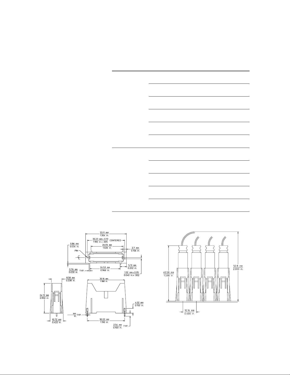
Figure 36. Mechanical information for E5346-44701, E5346-44703,
E5346-44704 support shrouds for 38-pin Mictor connectors
0.64
0.025
Page 30
30
Designing and Probing with Target Connections
Probing Individual Pins of High-Density Connectors
38-pin Mictor Adapter
Signals routed out to AMP Mictor
connectors can also be accessed
by other test equipment, such
as an oscilloscope.
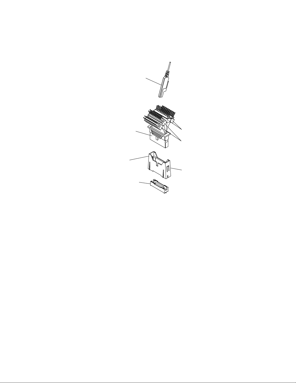
The E5346-60002 plugs directly
into the Mictor connector and
brings all 32 signals out to
standard connector pins through
flex circuits, as shown in
figure 37.
Figure 37. E5346-60002 Mictor break-out adapter
Probe
Multi-purpose
flexible cable
Pin 1 bevel
Mictor
Shroud
Even # probes
Odd # probes
Page 31
31
Designing and Probing with Target Connections
Right-Angle Mictor Adapter
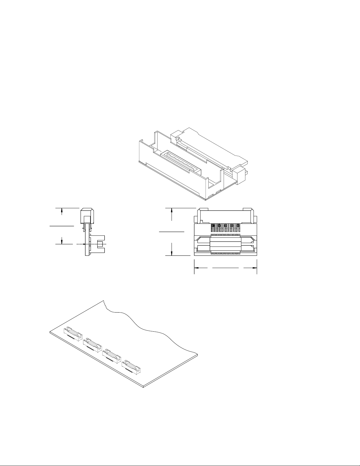
For systems with space
constraints above the 38-pin
connector, Agilent Technologies
offers a right-angle adapter, as
shown in figure 38. With the
E5346-63201 right-angle adapter
inserted in the 38-pin connector,
the adapter cable is connected
parallel to the target board
surface. When using the
right-angle adapters, the 38-pin
connectors must be placed
end-to-end on the target board,
as shown in figure 39. Support
shrouds cannot be used with the
right-angle adapter.
Figure 39. 38-pin connectors placed for use of right-angle adapter
Figure 38. E5346-63201 right-angle 38-pin adapter
Note: the right-angle adapter
adds significant capacitance and
inductance in series with the
probe. It is not recommended for
state speeds above 100 MHz or for
signals with rise times < 4 - 5 ns.
0.575 in
14.61mm
0.382 in
9.69 mm
0.758 in
19.26 mm
1.00 in
25.40 mm
Page 32
32
Designing and Probing with Target Connections
Agilent Logic Analyzers with 90-pin Pod Connectors
Five options are available for
connecting the Agilent logic
analyzers with 90-pin pod
connectors to a target system
using mass connections.
Agilent soft-touch connectorless
probes
Agilent’s soft-touch
connectorless probes use
spring-loaded pin technology
to provide reliable contact which
is not dependent on the planarity
of the PC board or the plating
processes used to fabricate the
board. No special cleaning
processes are required when
using Agilent’s soft-touch probes.
Refer to figures 40 through 43
on pages 32 and 33 for
dimensional drawings, board
contact dimensions, and load
models for soft touch probes.
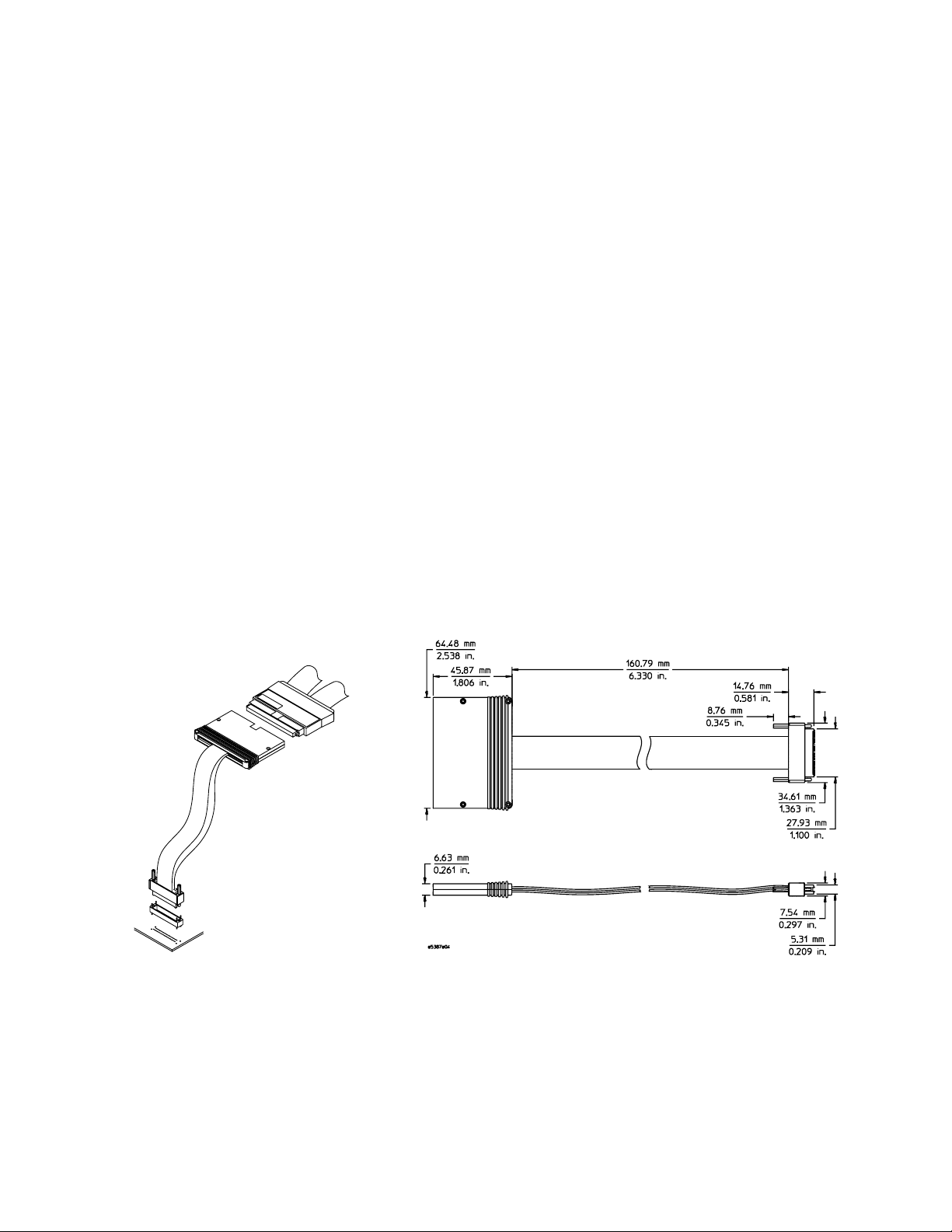
The E5387A is a 17-channel differential probe capable of acquiring data up to 1.5 Gb/s (when
used with the Agilent 16760A).
The probe has the following
inputs:
• 16 differential data inputs
• 1 differential clock input.
The clock input can be used as a
data input if not used as a clock
or qualifier.
Figure 40. E5387A soft touch differential probe
Logic Analyzer
Probe Cable
Soft Touch
Probe
Retention
Module
Pads & Mounting Holes
on Target System
Figure 41. Soft touch probe (E5387A and E5390A) dimensions
E5390A soft touch single-ended probe
(available first quarter 2003)
The E5390A is a 34-channel
single-ended probe capable of
acquiring data up to 1.5 Gb/s
(when used with the Agilent
16760A). The probe has the
following inputs:
• 34 single-ended data inputs
• 2 differential clock inputs.
• 2 data reference threshold
inputs
The clock inputs can be used as
data inputs if not used as a clock
or qualifier.
Page 33
33
Designing and Probing with Target Connections
Agilent Logic Analyzers with 90-pin Pod Connectors
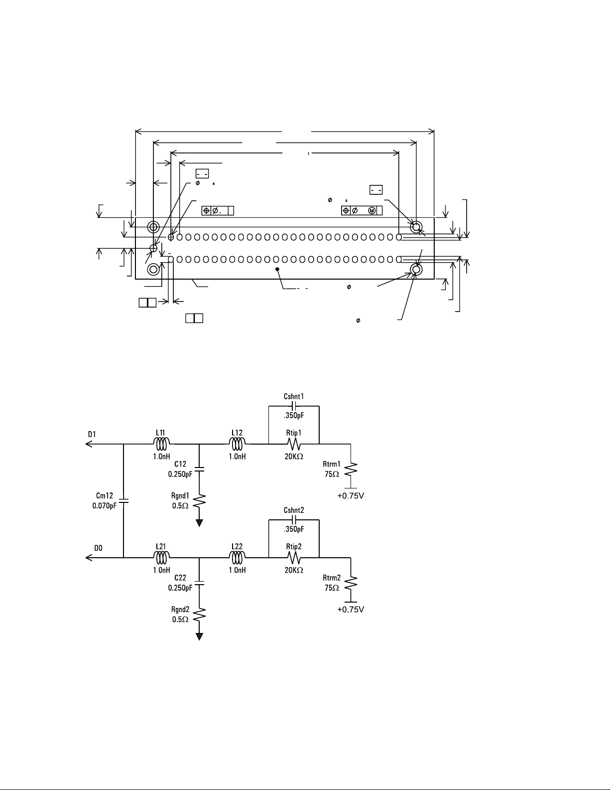
Figure 42. Soft touch probe (E5387A and E5390A) probe PC board layout dimensions
Figure 43. Load model for soft touch probes
Agilent soft touch probes
require a retention module
mounted to the target printed
circuit board. A kit of 5
retention modules is shipped
with each soft touch probe.
Additional kits can be
ordered, Agilent part
number E5387-68701.
34.04 mm
26.00 mm
29.97 mm
2.53 mm
6.99 mm
3.25 mm
1.35 mm
retention hole pads
both sides
0.79 0.08 mm
pth 4x
1.83 mm
1.00 mm typ
2.03 mm
3.49 mm
1.27 mm
2.41 mm
pad height 54x
1
2
1
B
B27
A27
C
A
.15 B
.15 B
R 0.29 mm
2
0.58 mm
pad width 54x
footprint keep
out boundary
0.81 0.03 mm
(keying/alignment hole)
0.79 0.08 mm pth
A1
B1
0.71 mm
Page 34

34
E5390A Single-ended Soft Touch Probe Pin-out
PAD# Pod Input PAD# Pod Input
A1 Odd D1 B1 Odd D0
A2 Odd D3 B2 Odd D2
A3 Ground B3 Ground
A4 Odd D5 B4 Odd D4
A5 Odd D7 B5 Odd D6
A6 Ground B6 Ground
A7 Odd D9 B7 Odd D8
A8 Odd D11 B8 Odd D10
A8 Ground B9 Ground
A10 Odd D13 B10 Odd D12
A11 Odd D15 B11 Odd D14
A12 Ground B12 Ground
A13 Odd CLKN/D16N B13 Odd CLKP/D16P
A14 Ground B14 Ground
A15 Even D1 B15 Even D0
A16 Even D3 B16 Even D2
A17 Ground B17 Ground
A18 Even D5 B18 Even D4
A19 Even D7 B19 Even D6
A20 Ground B20 Ground
A21 Even D9 B21 Even D8
A22 Even D11 B22 Even D10
A23 Ground B23 Ground
A24 Even D13 B24 Even D12
A25 Even D15 B25 Even D14
A26 Ground B26 Ground
A27 Even CLKN/D16N B27 Even CLKP/D16P
Table 9. Pin assignments for single-ended soft touch probe, E5390A
Designing and Probing with Target Connections
Agilent Logic Analyzers with 90-pin Pod Connectors
Page 35

35
E5387A Differential Soft Touch Probe Pin-out
PAD# Pod Input PAD# Pod Input
A1 nD0 (-) B1 D0 (+)
A2 nD1 (-) B2 D1 (+)
A3 Ground B3 Ground
A4 nD2 (-) B4 D2 (+)
A5 nD3 (-) B5 D3 (+)
A6 Ground B6 Ground
A7 nd4 (-) B7 D4 (+)
A8 nD5 (-) B8 D5 (+)
A8 Ground B9 Ground
A10 nD6 (-) B10 D6 (+)
A11 nD7 (-) B11 D7 (+)
A12 Ground B12 Ground
A13 nCLOCK (-) B13 CLOCK (+)
A14 Ground B14 Ground
A15 nD8 (-) B15 D8 (+)
A16 nD9 (-) B16 D9 (+)
A17 Ground B17 Ground
A18 nD10 (-) B18 D10 (+)
A19 nD11 (-) B19 D11 (+)
A20 Ground B20 Ground
A21 nD12 (-) B21 D12 (+)
A22 nD13 (-) B22 D13 (+)
A23 Ground B23 Ground
A24 nD14 (-) B24 D14 (+)
A25 nD15 (-) B25 D15 (+)
A26 Ground B26 Ground
A27 N/C B27 N/C
Table 10. Pin assignments for differential soft touch probe, E5387A
Designing and Probing with Target Connections
Agilent Logic Analyzers with 90-pin Pod Connectors
Page 36
36
E5378A 100-Pin Single-Ended Probe
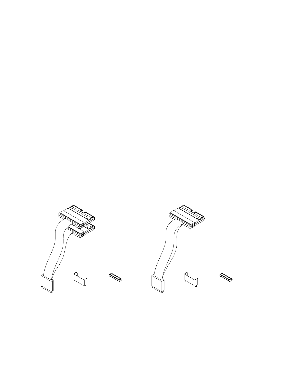
The E5378A is a 34-channel
single-ended probe capable of
capturing data up to 1.5 Gbits/sec
(see figures 51 and 53 for probe
dimensions and equivalent
load). The probe has the
following inputs:
• 32 single-ended data inputs,
in two groups (pods) of 16.
• Two differential clock inputs.
Either or both clock inputs can
be acquired as data inputs if
not used as a clock.
• Two data threshold reference
inputs, one for each pod (group
of 16 data inputs).
E5379A 100-Pin Differential Probe
The E5379A is a 17-channel
differential probe capable of
capturing data up to 1.5 Gbits/sec
(see figures 52 and 53 for probe
dimensions and equivalent
load). The probe has the
following inputs:
• 16 differential data inputs.
• One differential clock input.
The clock input can be
acquired as a data input if it
is not used as a clock.
Refer to table 11 on page 38 for
part numbers for mating
connectors and shrouds.
Figure 44. Agilent E5378A probe Figure 45. Agilent E5379A probe
E5378A
Single-ended Probe
E5379A
Differential Probe
Probing Connector Kit
Probing Connector Kit
Shrouds (5)
Shrouds (5)
100-pin
connectors (5)
100-pin
connectors (5)
See table 9 for
part numbers
Designing and Probing with Target Connections
Agilent Logic Analyzers with 90-pin Pod Connectors
Page 37
37
Designing and Probing with Target Connections
Agilent 16760A 1.5 Gbits/Sec Logic Analyzer Module
E5386A Half-Channel Adapter
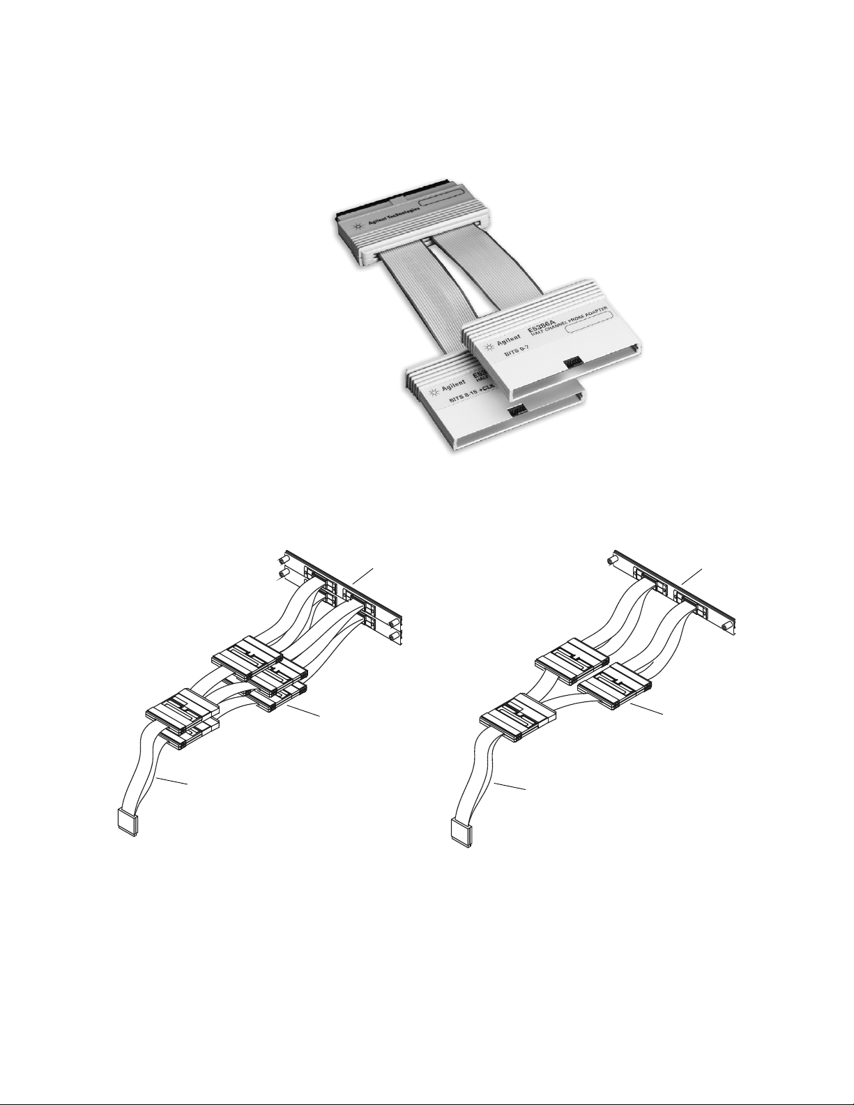
When the Agilent 16760A is
operated in the 1250 Mb/s or
1500 Mb/s mode, only the even
numbered channels are used.
To reduce the number of probes
and connectors required, the
E5386A adapter maps the even
channels to all of the pins of an
E5378A, E5379A, E5387A, or
E5390A probe. The E5386A halfchannel adapter is usable with
either the E5378A or E5387A
single-ended probe or the E5379A
or E5390A differential probe.
The following diagrams show how
the E5386A is connected.
Figure 46. E5386A half-channel probe adapter.
Figure 47. E5386A with E5378A or E5390A
single-ended probe.
Figure 48. E5386A with E5379A or E5387A
differential probe.
E5386A (2)
E5378A or E5390A
16760A (2)
E5379A or E5387A
E5386A (1)
16760A
Page 38
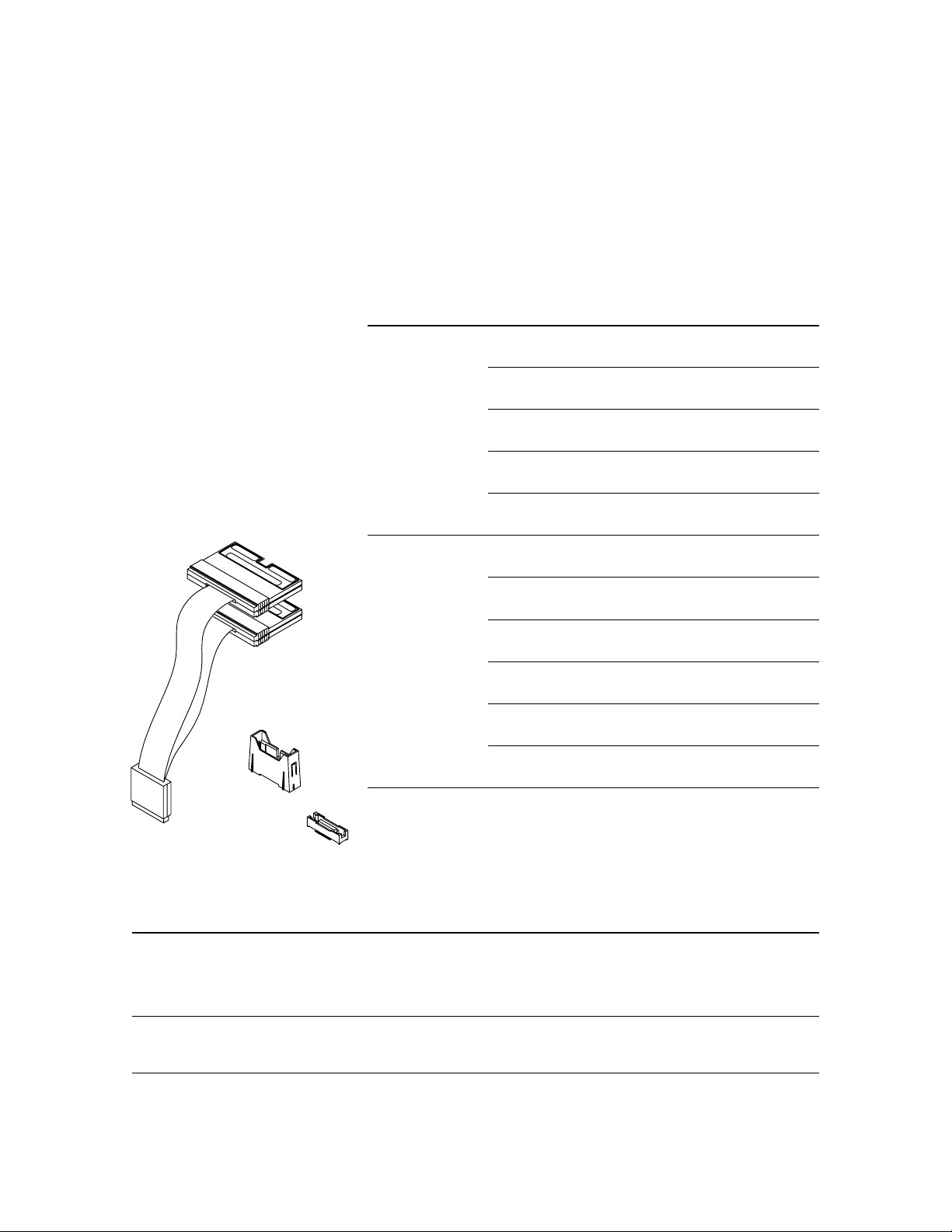
38
Designing and Probing with Target Connections
Agilent Logic Analyzers with 90-pin Pod Connectors
E5380A 38-Pin Probe
The E5380A is designed to be
compatible with the Agilent
E5346A high-density probe
adapter and the Mictor connector.
If you have a target system
designed for connection to the
E5346A high-density probe
adapter, the E5380A probe will
connect directly to this same
Mictor connector. (For
information on the E5346A,
refer to pages 23-24). The
maximum state speed when
used with the E5380A probe is
600 Mbits/second. The minimum
input signal amplitude required
by the E5380A is 300 mV.
For further information on designing the E5378A, E5379A, or E5380A probe connectors into your system, refer to the following documents:
Agilent Technologies Logic Analyzer Probes Mechanical drawings, 16760-97008 http://cp.literature.agilent.com/litweb/pdf/16760-97008.pdf
(E5378A, E5379A, E5380A, and E5386A) electrical models, general
User’s Guide information on probes
for logic analyzers with
90-pin connectors
Designing High-Speed Digital Systems for Design recommendations, 5988-2989EN http://www.agilent.com/find/probeguide
Logic Analyzer Probing examples, and analysis for
layout of target systems
38-pin Probe
For probe Agilent
model numbers Description part number
E5378A, E5379A Kit of 5 support shrouds and 5 100-pin Samtec connectors 16760-68702
for PC board thickness up to 1.57 mm (0.062")
Kit of 5 support shrouds and 5 100-pin Samtec connectors 16760-68703
for PC board thickness up to 3.05 mm (0.120")
One 100-pin Samtec connector 1253-3620
(also available from Samtec as part number ASP-65067-01)
One support shroud 16760-02302
for PC board thickness up to 1.57 mm (0.062")
One support shroud 16760-02303
for PC board thickness up to 3.05 mm (0.120")
E5380A Kit of 5 support shrouds and 5 38-pin Mictor connectors E5346-68701
for PC board thickness up to 1.57 mm (0.062")
Kit of 5 support shrouds and 5 38-pin Mictor connectors E5346-68700
for PC board thickness up to 3.175 mm (0.125")
One 38-pin Mictor connector 1252-7431
(also available from AMP as part number 2-767004-2)
One support shroud E5346-44701
for PC board thickness up to 1.57 mm (0.062")
One support shroud E4346-44704
for PC board thickness up to 3.175 mm (0.125")
One support shroud E5346-44703
for PC board thickness up to 4.318 mm (0.700")
Table 11. Mating connectors, shrouds, and kits for Agilent E5378A, E5379A, and
E5380A probes
The E5380A probe combines
two 17-channel cables into a
single-ended 38-pin Mictor
connector.
Refer to table 11 for connector,
shroud, and kit part numbers.
Probing Connector Kit
Shrouds (5)
Figure 49. Agilent E5380A probe
38-pin
connectors (5)
See table 9 for
part numbers
Page 39
39
Designing and Probing with Target Connections
Agilent Logic Analyzers with 90-pin Pod Connectors
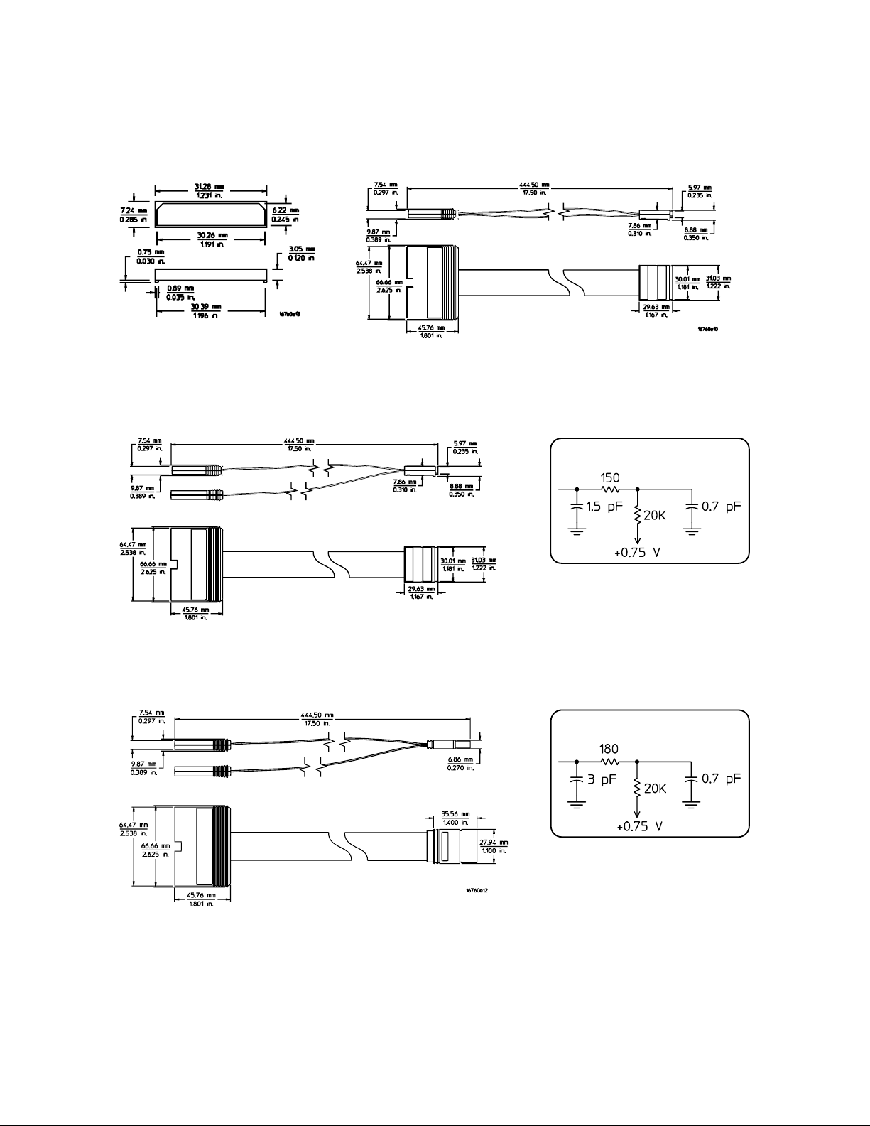
Figure 50. Dimensions of the 100-Pin
Samtec connector used in the
16760-68702 and 16760-68703
connector kits
Figure 51. E5378A 100-pin single-ended probe dimensions
Figure 52. E5379A 100-pin differential probe dimensions
Figure 53. E5378A and E5379A input
equivalent load, including 100-pin
connector
Figure 55. E5380A input equivalent load,
including 38-pin connector
Equivalent Load
Equivalent Load
Figure 54. E5380A 38-Pin probe dimensions
Page 40
40
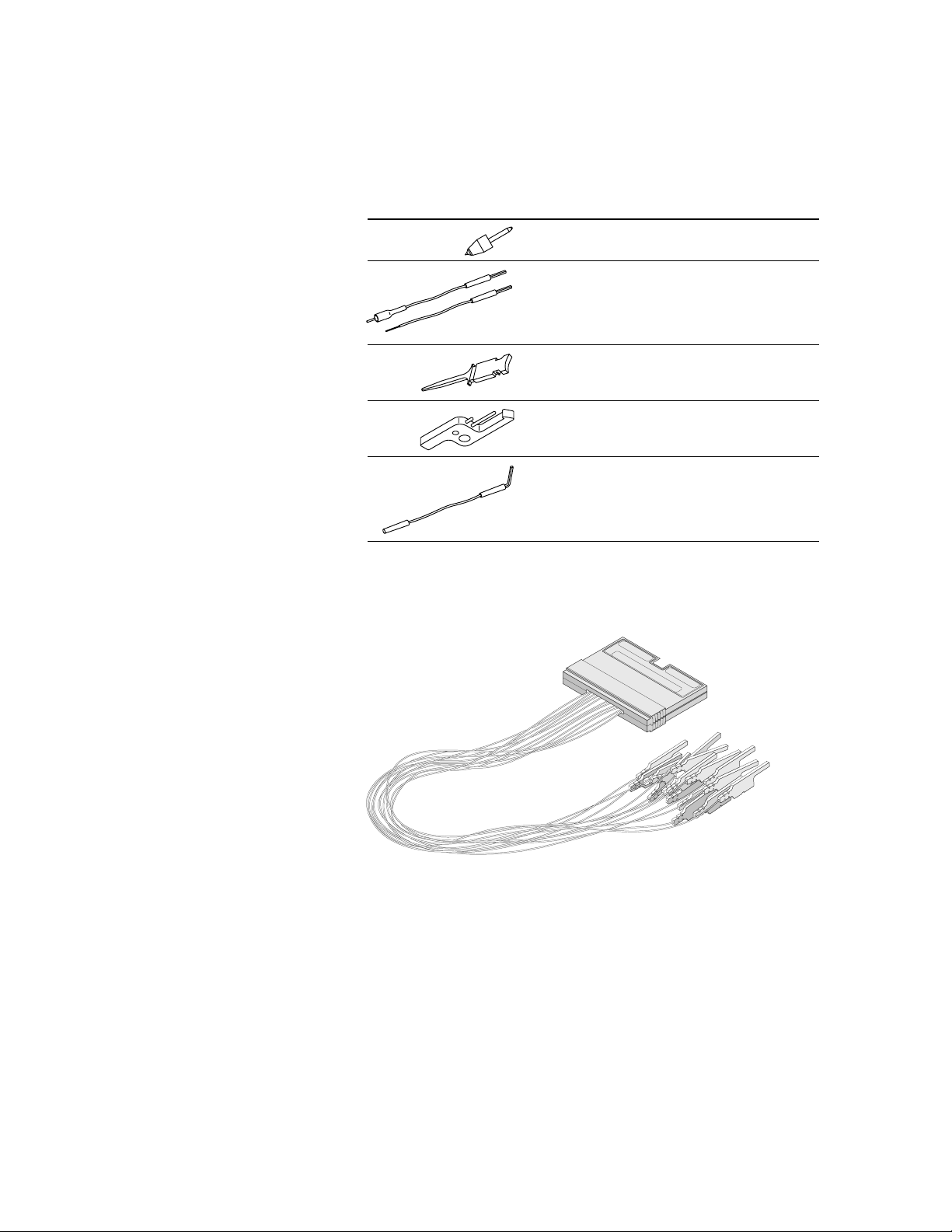
Part number Description
E5382-82102 Probe pin kit, 2 resistive pins per kit
E5382-82101 High-frequency probing kit,
2 resistive signal wires and
4 ground wires per kit
16517-82109 Grabber clip kit, 20 grabbers per kit
16517-82105 Ground extender kit,
20 ground extenders per kit
16517-82106 Right-angle ground lead kit,
20 ground leads per kit
Table 12. Accessories.
General-Purpose Probing
Agilent Logic Analyzers with 90-pin Pod Connectors
E5382A Single-ended Flying Lead
Probe Set
The E5382A 17 channel singleended flying lead probe set
compatible with logic analyzers
with a 90-pin pid connection.
Accessories supplied with the
flying leads are shown in
table 12.
Figure 56. E5382A flying lead set
Page 41
41
General-Purpose Probing
Agilent Logic Analyzers with 90-pin Pod Connectors
Suggested Configurations and Characteristics
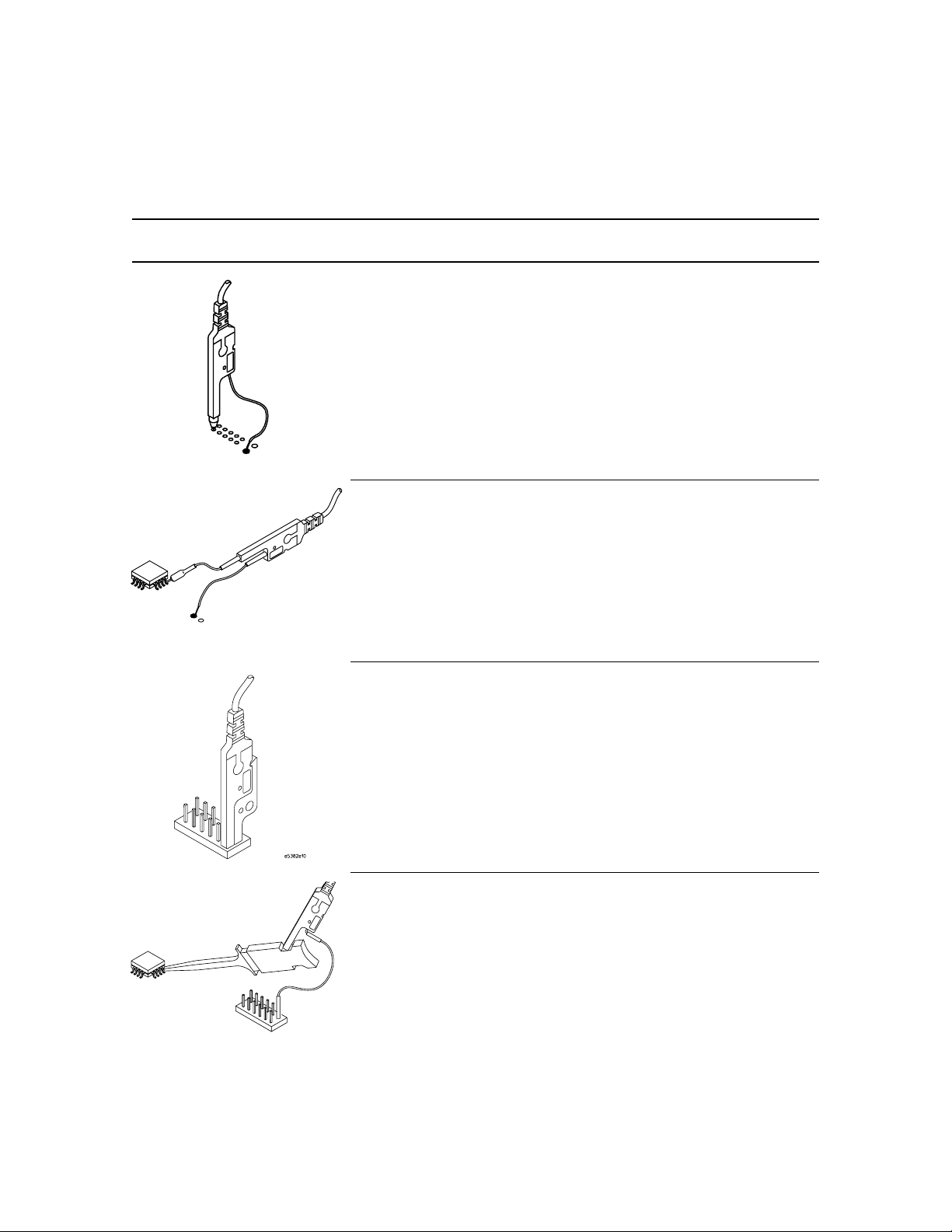
Configuration Description Total lumped Maximum recommended
input C state speed
130 Ω Resistive Signal 1.3 pF 1.5 Gb/s
Pin (orange) and Solderdown Ground Lead
5 cm Resistive Signal 1.6 pF 1.5 Gb/s
Lead (can be Soldered-down)
and Solder-down Ground Lead
Flying Lead and Ground 1.4 pF 1.5 Gb/s
Extender
Grabber Clip and 2.0 pF 600 Mb/s
Right-angle 2.0 pF
Ground Lead
Table 13. E5382A suggested configurations and characteristics
Page 42
42
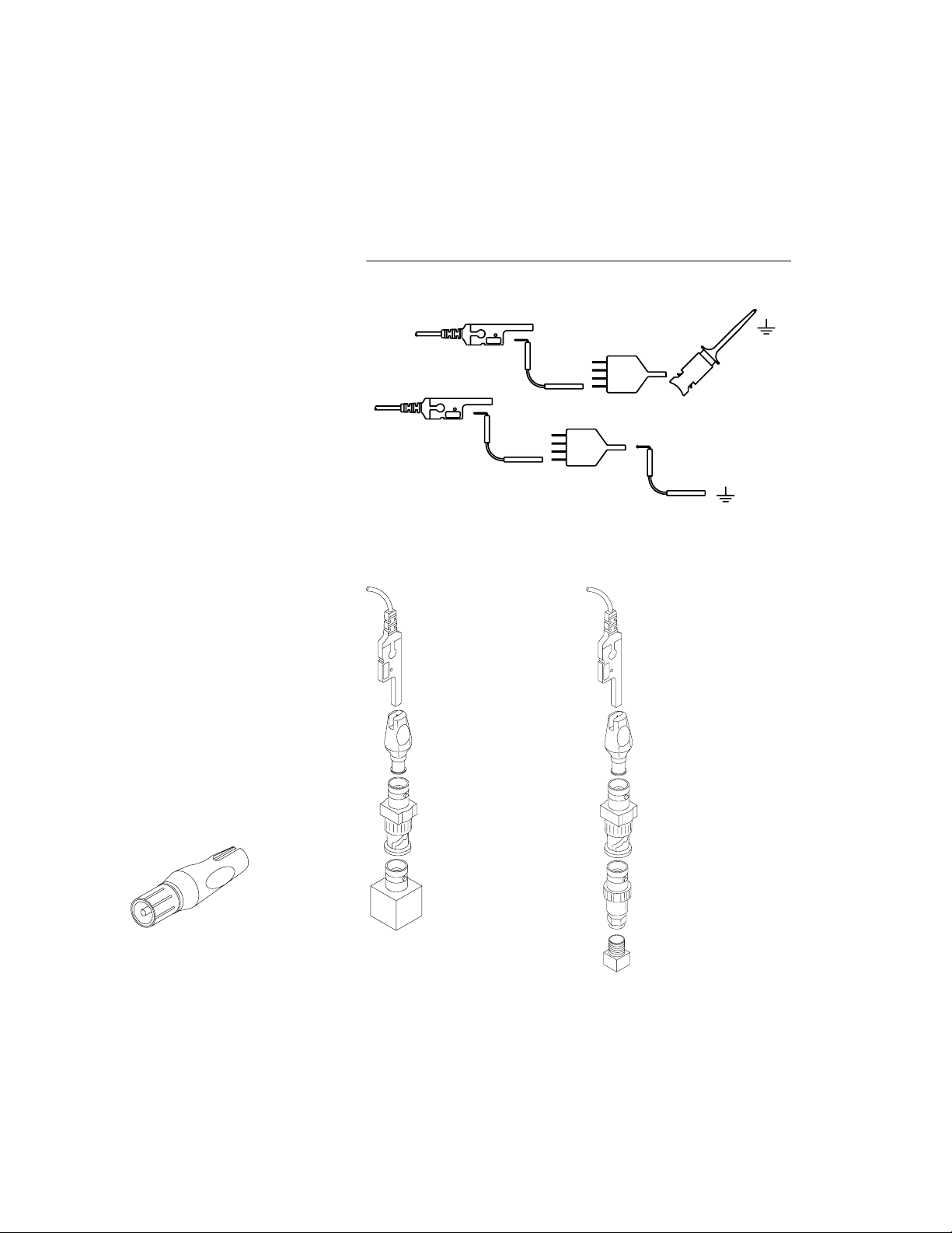
Figure 57. E9638A BNC to
probe tip adapter
General-Purpose Probing
Agilent Logic Analyzers with 90-pin Pod Connectors
Available Accessories
Ground connector
It is essential to ground every tip
that is in use. For best performance at high speeds, every tip
should be grounded individually
to ground in the system under
test. For convenience in connecting grounds, you can use the
ground connector, Agilent part
number 16515-27601, to combine
up to four probe tip grounds to
connect to one ground point in
the system under test.
Adapting to coaxial connectors
The Agilent E9638A probe tip to
BNC adapter can be used to
connect one of the flying lead
probes of the E5382A to a BNC
connector. To probe other coaxial
connectors, use the E9638A
adapter, a BNC termination, and
an adapter to the other type of
coaxial connector. Refer to
figure 58.
Probe Tip
E9638A Probe tip to
BNC Adapter
BNC 50 Ω Feedthrough
Termination Adapter
BNC to SMA, SMB, SMC,
or other Coaxial Adapter
SMA, SMB, SMC, or
other Coaxial Connector
Probe Tip
E9638A Probe tip to
BNC Adapter
BNC 50 Ω Feedthrough
Termination Adapter
BNC Connector
Figure 58. Recommended configurations to probe RF coaxial connectors with
the E5382A flying lead probes
NOTE: Examples of convenient connection which
may result in degraded performance
SIG.
SIG.
"GND CONNECTOR"
16515-27601
Page 43
43
General-Purpose Probing
Agilent Logic Analyzers with 90-pin Pod Connectors
E5381A differential flying-lead
probe set
The E5381A is a 17 channel
differential flying-lead probe set,
capable of probing differential or
single-ended signals, compatible
with logic analyzer with a 90-pin
pod connection.
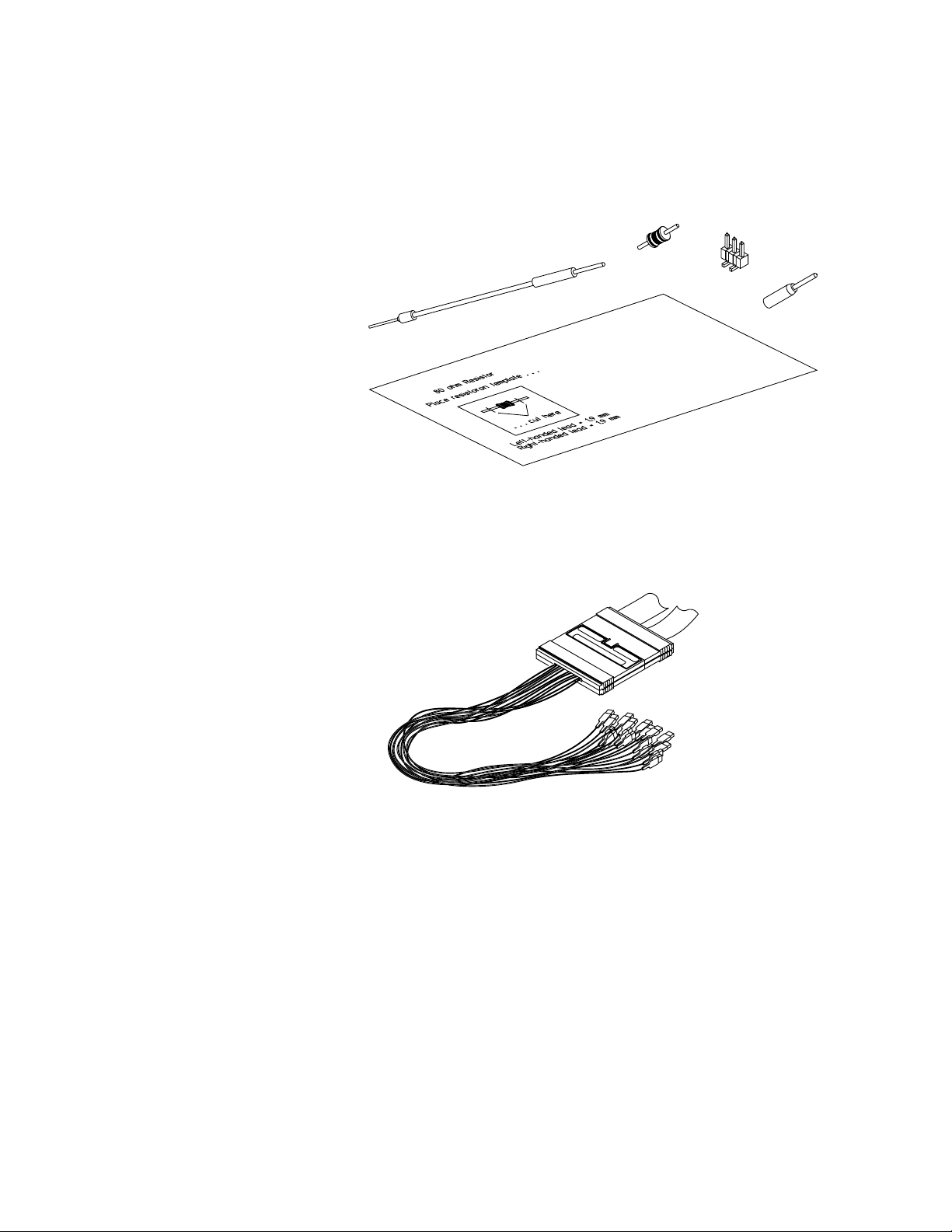
Figure 59. E5381A differential flying-lead probe set accessories
Figure 60. E5381A differential flying-lead probe set
Damped
Wire
Coaxial Tip
Resistor
3-Pin
Header
Socket
Adapter
82 Ω Resistor Trimming Template
Page 44
44
General-Purpose Probing
Agilent Logic Analyzers with 90-pin Pod Connectors
Suggested Configurations and Characteristics
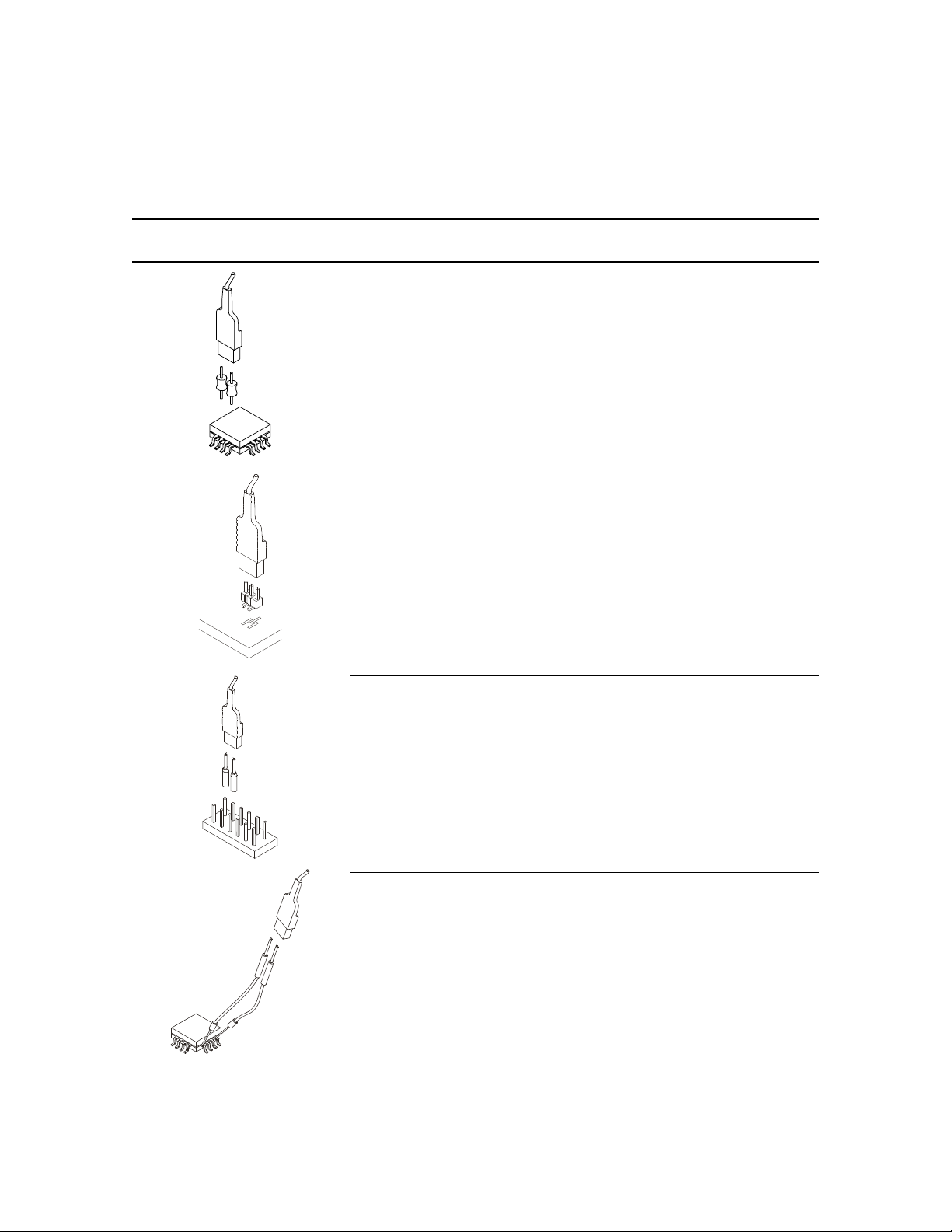
Configuration Description Total lumped Maximum recommended
input C state speed
Coaxial Tip 0.9 pF 1.5 Gb/s
Resistor (82 Ω blue)
Solder Attach to Components,
Traces, Pads, or VIAs.
3-pin Header 1.0 pF 1.5 Gb/s
Socket Adapter 1.1 pF 1.5 Gb/s
Damped Wire 1.3 pF 1.5 Gb/s
Solder Attach to Components,
Traces, Pads, or VIAs.
Table 14. E5381A suggested configurations and characteristics
Page 45
45
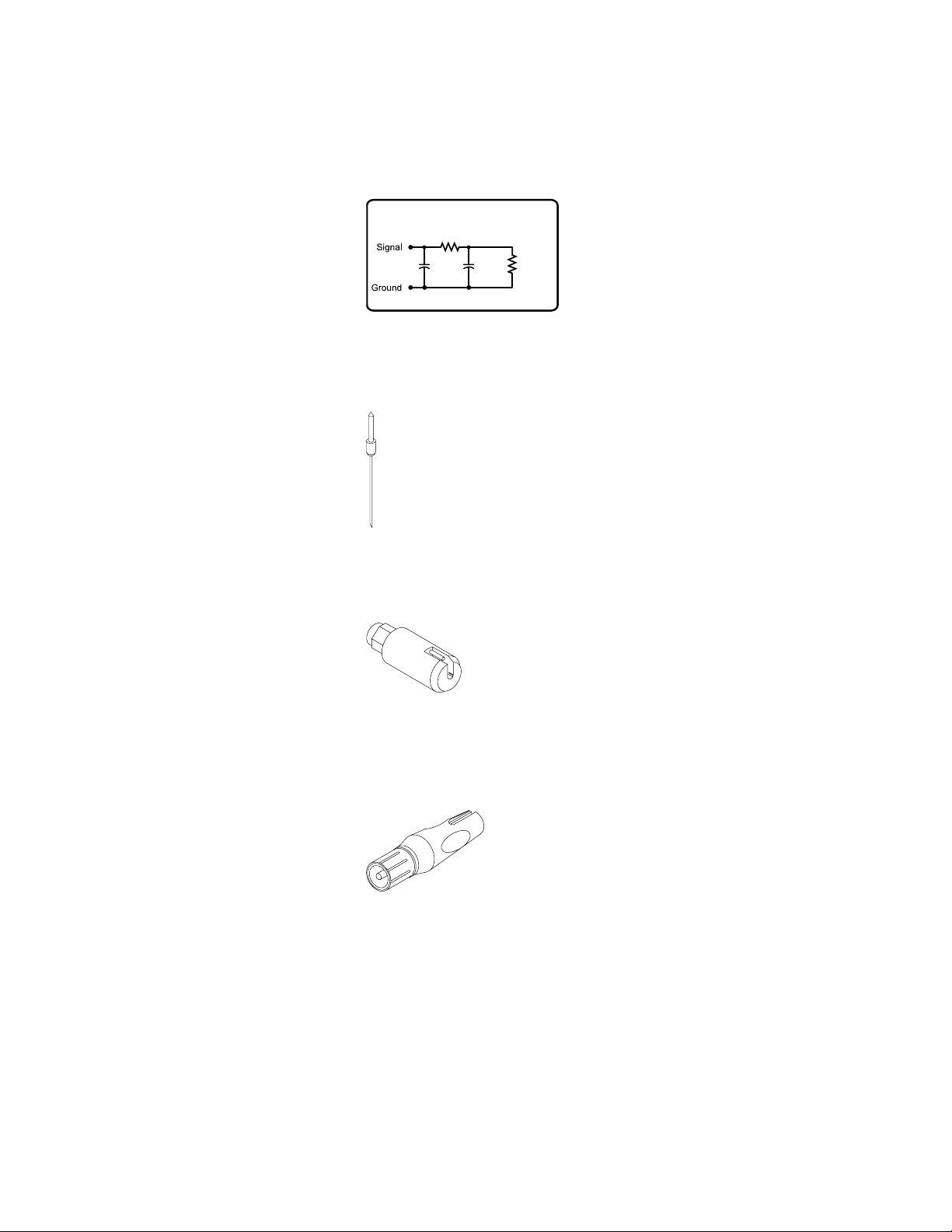
100k
ohm
0.2pF 3pF
500 ohm
Agilent 16517A/16518A 1 GHz State / 4 GHz Timing
High-Speed Logic Analysis
General-Purpose Probes
The Agilent 16517A and 16518A
logic analysis modules were
discontinued in April 2002.
Probing accessories for these
modules are listed here for convenience in ordering additional
accessories if needed.
Special Connectors
The Agilent 16517A/16518A can
conveniently probe an SMA or
BNC connector with the adapters
shown in figures 63 and 57. The
flexible ground pin, figure 56,
provides excellent signal fidelity
when used as shown in figure 66.
Figure 63. 16517-27601 SMA adapter
Includes logic analyzer
Figure 62. E5320-26101
flexible ground pin
Figure 61. Equivalent load for high-speed
general-purpose probe
Equivalent Load
Figure 64. E9638A Probe tip to BNC
adapter
9 pF
Page 46
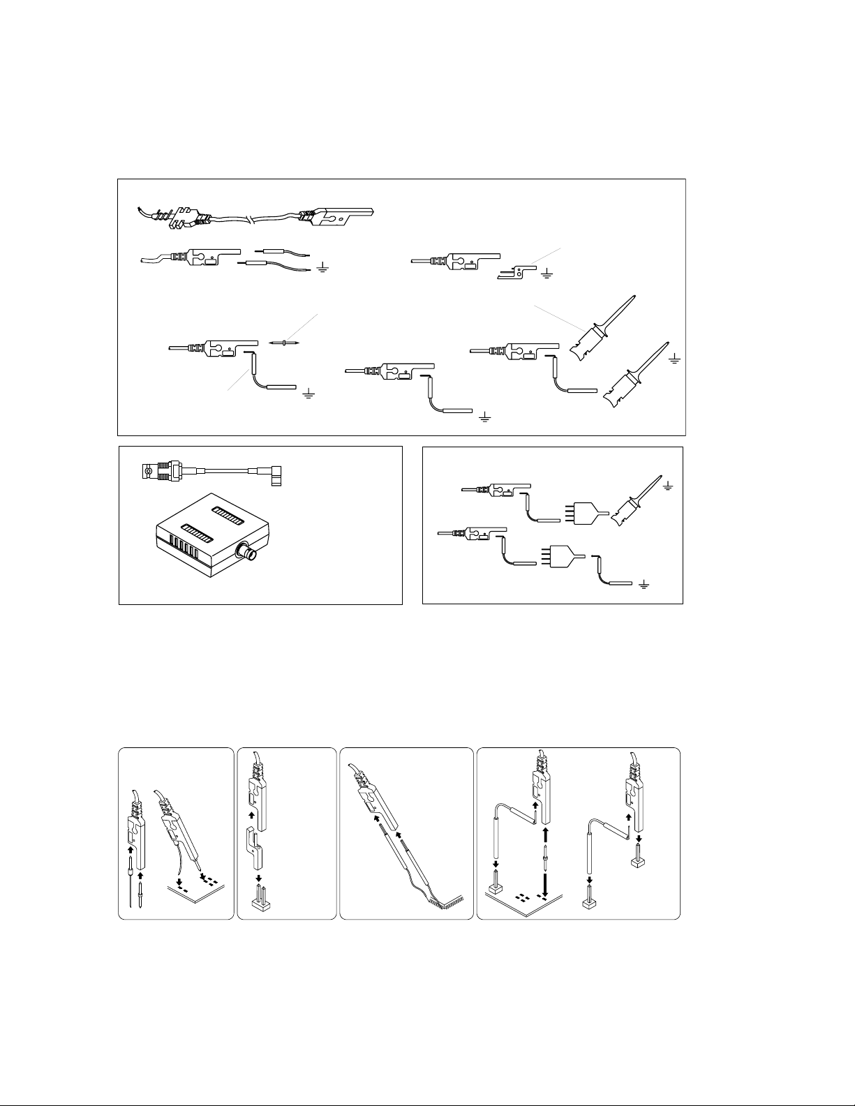
46
Agilent 16517A/16518A 1 GHz State / 4 GHz Timing
Figure 65. Agilent Technologies 16517-68701 master accessory kit and 16518-68701 expansion accessory kit
Figure 66. Probing configurations that give the best signal fidelity
Probing Configurations
"PROBE LEAD"
16517-61602
SIG.
"SMT KIT"
16517-82104
Qty. 4 Black Incl.
Qty. 4 Red Incl.
"GND LEAD KIT"
16517-82106
Qty. 20 incl.
"PIN-PROBE KIT"
16517-82107
Qty. 4 Incl.
SIG.
SIG.
"SMD IC CLIP KIT"
16517-82109
Qty. 20 incl.
"GND EXTENDER KIT"
16517-82105
Qty. 20 incl.
SIG.
"ADAPTER CABLE"
BNC-SMB
16517-61604
"CALIBRATION POD"
16517-63201
These parts included in the
16517-68701 MASTER KIT only
Recommended Probe Configurations
NOTE: Examples of convenient connection which
may result in degraded performance
SIG.
SIG.
"GND CONNECTOR"
16515-27601
For the best performance, use the following configurations. The configurations are listed in the recommended order.
Flexible Direct Ground Pin Ground Extender SMT Tack-on Signal/Ground
Make contact with
the flexible ground
first, then flex it to
place the signal
pin.
Signal
Signal
Ground
Signal
Ground
0.635mm (0.025")
square pin or
0.66-0.84mm
diameter pin
Ground
Black
Red
Pin and Socket Ground Lead
Ground
Signal
Ground
0.635mm (0.025")
square pin or
0.66-0.84mm
diameter pin
Signal
Page 47

47
Ordering Information
Accessories Supplied with Logic Analyzers
Accessories Supplied with Agilent 16517A/16518A Logic Analyzer Modules
Part Number Description Quantity Page Number
16517-68701 4 GHz timing modules master accessory kit (includes items below) 1 46
16515-27601 Ground connector 2 46
16517-61602 Probe lead assembly 1 46
16517-61604 BNC-SMB adapter cable 1 46
16517-63201 Calibration pod 1 46
16517-82104 SMT lead kit (package of 4 black and 4 red) 1 46
16517-82105 Ground extender kit (package of 20) 1 46
16517-82106 Ground lead kit (package of 20) 1 46
16517-82107 Pin probe kit (package of 4) 1 46
16517-82109 SMD IC clip kit (package of 20) 1 46
Accessories Supplied with Agilent 16557D Logic Analyzer Modules
Part Number Description Quantity Page Number
01650-61608 16-channel probe lead set 4 9
01650-94312 Logic analyzer probe labels 1 13
5090-4833 SMD IC clips, surface mount (package of 20) 4 10
5959-9333 Probe leads, gray (package of 5) 1 9
5959-9334 Short ground leads (package of 5) 4 9
16555-61601 Master/expander interconnect cable 1 not shown
Accessories Supplied with Agilent 1670G Series Logic Analyzers
Part Number Description Quantity Page Number
01650-61608 16-channel probe lead set 8 (1670G), 6 (1671G) 9
4 (1672G), 2 (1673G)
01670-94307 Logic analyzer probe labels 1 13
5090-4833 SMD IC clips, surface mount (package of 20) 8 (1670G), 6 (1671G) 10
4 (1672G), 2 (1673G)
5959-9334 Short ground leads (package of 5) 1 9
Accessories Supplied with Agilent 16710A/16711A/16712A Logic Analyzer Modules
Part Number Description Quantity Page Number
01650-61608 16-channel probe lead set 6 9
01650-94312 Logic analyzer probe labels 1 13
5090-4833 SMD IC clips, surface mount (package of 20) 6 10
5959-9333 Probe leads, gray (package of 5) 1 9
5959-9334 Short ground leads (package of 5) 6 9
16555-61601 Master/expander interconnect cable 1 not shown
Accessories Supplied with Agilent 16715A/16716A/16717A/16740A/16741A/16742A/16750A/B/16751A/B/16752A/B
Logic Analyzer Modules
Part Number Description Quantity Page Number
01650-61608 16-channel probe lead set 4 9
01650-94312 Logic analyzer probe labels 1 13
5090-4833 SMD IC clips, surface mount (package of 20) 4 10
5959-9333 Probe leads, gray (package of 5) 1 9
5959-9334 Short ground leads (package of 5) 4 9
Accessories Supplied with Agilent 1680 and 1690 Series Logic Analyzers
Part Number Description Quantity Page Number
01650-61608 16-channel probe lead set 8 (1680A/AD, 1690A/AD), 6 (1681A/AD, 1691A/AD) 9
4 (1682A/AD, 1692A/AD), 2 (1683A/AD, 1693A/AD)
01680-94313 Logic analyzer probe labels 1 13
5090-4833 SMD IC clips, surface mount (package of 20) 8 (1680A/AD, 1690A/AD), 6 (1681A/AD, 1691A/AD) 10
4 (1682A/AD, 1692A/AD), 2 (1683A/AD, 1693A/AD)
5959-9334 Short ground leads (package of 5) 8 (1680A/AD, 1690A/AD), 6 (1681A/AD, 1691A/AD) 9
4 (1682A/AD, 1692A/AD), 2 (1683A/AD, 1693A/AD)
Page 48

48
Ordering Information
State ≤ 400 MHz/Timing ≤ 800 MHz
General-Purpose Probing
1, 2
Probe Leads and Lead Sets
Part Number Description Page Number
01650-61608 16-channel probe lead set 9
5959-9333 Probe leads, gray (package of 5) 9
5959-9334 Short ground leads (package of 5) 9
5959-9335 Long ground leads (package of 5) 9
Probe Cables
Part Number Description Page Number
01660-61605 For 16550A logic analyzers 11
16555-61606 For 16554A, 16555A/D, 16556A/D logic analyzers 11
16710-61603 For 16557D, 16710A, 16711A,16712A, and 16706 series logic analyzers 11
16715-61601 For 16715A, 16716A, 16717A, 16718A, 16719A,16750A/B, 16751A/B, 16752A/B,
1680 and 1690 series logic analyzers 11
IC Clips
Part Number Description Page Number
5959-0288 Through-hole IC clip kit, (package of 20) 10
5090-4833 SMD IC clip kit, (package of 20) 10
10467-68701 0.5 mm IC clip kit (package of 4) 10
IC Test Clips
Product Number Description Page Number
E2421A SOIC test clip kit (Pomona 5514), small outline 10
E2422A QUAD test clip kit (Pomona 5515), four-sided small outline 10
Wedge Adapters
Product Number Description Page Number
E2613A 0.5 mm probe adapter-3 signal 12
E2613B 0.5 mm probe adapter-3 signal-2 pack 12
E2614A 0.5 mm probe adapter-8 signal 12
E2643A 0.5 mm probe adapter - 16-signal 12
E2615A 0.65 mm probe adapter-3 signal 12
E2615B 0.65 mm probe adapter-3 signal-2 pack 12
E2616A 0.65 mm probe adapter-8 signal 12
E2644A 0.65 mm probe adapter -16-signal 12
Miscellaneous Probing Accessories
Part Number Description Page Number
01650-94303 Logic analyzer probe labels 13
16555-60001 Ferrite core assembly 13
1 Check on page 36 for accessories supplied with a specific logic analyzer.
2 Individual flying lead probes are not available for the 16760A.
Page 49

49
Ordering Information
State ≤ 400 MHz/Timing ≤ 800 MHz
Elastomeric Probing for QFP Packages
Product Number Description Page Number
E5336A 144-pin 0.5 mm TQFP elastomeric probe adapter
1
14-16
E5336A 201 Retainer kit (5 retainers and adhesive) 14-16
E5336A 202 Locator tool 14-16
E5340A 1/4 flex adapter for use with the E5336A (quantity 1) 14-16
E5377A 160-pin 0.5 mm TQFP elastomeric probe adapter
1
14-16
E5377A 201 Retainer kit (5 retainers and adhesive) 14-16
E5377A 202 Locator tool 14-16
E5349A 1/4 flex adapter for use with the E5377A (quantity 1) 14-16
E5348A 176-pin 0.5 mm TQFP elastomeric probe adapter
1
14-16
E5348A 201 Retainer kit (5 retainers and adhesive) 14-16
E5348A 202 Locator tool 14-16
E5349A 1/4 flex adapter for use with the E5348A (quantity 1) 14-16
E5361A 144-pin 0.65 mm PQFP/CQFP elastomeric probe adapter
1
14-16
E5361A 201 Retainer kit (5 retainers and adhesive) 14-16
E5361A 202 Locator tool 14-16
E5340A 1/4 flex adapter for use with the E5361A (quantity 1) 14-16
E5373A 160-pin 0.65 mm PQFP/CQFP elastomeric probe adapter
1
14-16
E5373A 201 Retainer kit (5 retainers and adhesive) 14-16
E5373A 202 Locator tool 14-16
E5349A 1/4 flex adapter for use with the E5373A (quantity 1) 14-16
E5374A 208-pin 0.5 mm PQFP/CQFP elastomeric probe adapter
1
14-16
E5374A 201 Retainer kit (5 retainers and adhesive) 14-16
E5374A 202 Locator tool 14-16
E5371A 1/4 flex adapter for use with the E5374A (quantity 1) 14-16
E5363A 240-pin 0.5 mm PQFP/CQFP elastomeric probe adapter
1
14-16
E5363A 201 Retainer kit (5 retainers and adhesive) 14-16
E5363A 202 Locator tool 14-16
E5371A 1/4 flex adapter for use with the E5363A (quantity 1) 14-16
1 Each probe adapter includes 5 retainers, 1 locator tool, and adhesive.
Page 50

50
Ordering Information
State ≤ 400 MHz/Timing ≤ 800 MHz
Isolation Adapters and Connectors for Analysis Probes
Normal-Density, Medium-Performance Applications
Part Number Description Page Number
01650-63203 100 k ohm isolation adapter 18
1251-8106 20-pin connector 18
1251-8473 20-pin right angle connector not shown
1251-8828 40-pin, low profile connector (straight) 20-21
1251-8158 40-pin, low profile connector (right angle) not shown
1251-8831 40-pin connector with latches (straight) not shown
1251-8931 40-pin connector with latches (right angle) not shown
5062-7396 Isolation network, surface mount (quantity 1) 21
High-Density, High-Performance Applications
Part/Product Number Description Page Number
E5339A 38-Pin low-voltage probe 23-25
E5346A 38-Pin probe 23-25
E5351A 38-pin adapter cable 27-28
E5385A 100-pin probe 23-26
5062-7396 Isolation network, surface mount (quantity 1) 21, 28
E5346-44701 Mictor connector support shroud for PC boards up to 0.062” thick 29
E5346-68701 Mictor connector kit (5 connectors and 5 shrouds) for PC boards up to 0.062” thick 29
E5346-44704 Mictor connector support shroud for PC boards up to 0.125” thick 29
E5346-68700 Mictor connector kit (5 connectors and 5 shrouds) for PC boards up to 0.125” thick 29
E5346-44703 Mictor connector support shrouds for PC boards up to 0.170” thick 29
E5346-60002 Mictor break-out adapter 30
E5346-63201 High-density right-angle adapter 31
Page 51

51
Ordering Information
State > 400 MHz/Timing > 800 MHz
16760A 1.5 Gb/s Logic Analysis Module, and
16753A, 16754A, 16755A, and 16756A 600 MHz Logic Analysis Modules
Part/Product Number Description Page Number
E5378A 100-Pin single-ended probe for Logic Analyzers with 90-pin pod connectors 36
E5379A 100-Pin differential probe for Logic Analyzers with 90-pin pod connectors 36
E5380A 38-Pin single-ended probe for Logic Analyzers with 90-pin pod connectors 32
E5381A Differential flying lead probe set for analyzers with 90-pin pod connectors 42
E5382A Single-ended flying lead probe set for Logic Analyzers with 90-pin pod connectors 34
E5386A Half-channel probe adapter for 16760A 37
E5387A Differential soft touch probe for analyzers with 90-pin pod connectors 32
E5390A Single-ended soft touch probe for analyzers with 90-pin pod connectors 32
E5346-68700 Probing connector kit for E5380A 38
E5346-68701 Probing connector kit for E5380A 38
E5387-68701 Kit of 5 retention modules for E5387A, E5390A 33
16760-68702 Kit of 5 mating connectors and 5 support shrouds for 38
E5385A, E5378A and E5379A, for PC boards up to 0.062" thick
16760-68703 Kit of 5 mating connectors and 5 support shrouds for 38
E5385A, E5378A and E5379A, for PC boards up to 0.120" thick
16760-02302 Support shroud for E5385A, E5378A and E5379A, for 38
PC boards up to 0.062" thick
16760-02303 Support shroud for E5385A, E5378A and E5379A, for 38
PC boards up to 0.120" thick
1253-3620 100-pin mating connector for E5378A, E5385A, and E5379A 38
16517A/18A High-Speed Logic Analysis Modules
General-Purpose Probes
Part/Product Number Description Page Number
16517-61602 Probe lead assembly 46
16517-61604 BNC-SMB adapter cable 46
16517-63201 Calibration pod 46
16517-68701 4 GHz timing modules master accessory kit 46
16517-82104 SMT lead kit (package of 4 black and 4 red) 46
16517-82105 Ground extender kit (package of 20) 46
16517-82106 Ground lead kit (package of 20) 46
16517-82107 Pin probe kit (package of 4) 46
16517-82109 SMD IC clip kit (package of 20) 46
16518-68701 Expansion module accessory kit 46
5081-7753 Probe lead kit (set of 3 ea. 16517-61602) 46
E5320-26101 Flexible ground pin 45
16517-27601 SMA to probe tip adapter 45
E9638A BNC to probe tip adapter 45
16515-27601 Ground connector 42
Page 52

52
Related Information
Agilent Technologies logic analysis
third-party partners:
For a complete list of partners, see document 5966-4365EUS “Processor and
Bus Support for Agilent Technologies
Logic Analyzers.”
3M
http://www.mmm.com/interconnects
AMP, Inc.
Phone: 1-717-986-7777
Fax: 1-717-986-7575
Phone (USA only): 1-800-522-6752
E-mail: [email protected]
Web site: http://www.amp.com
Agilent Technologies Test and
Measurement Organization support
line phone number:
1-800-452-4844
Agilent Technologies Test and
Measurement Organization web site:
http://www.agilent.com
Agilent Technologies Test and
Measurement Logic AnalyzersSystems web site:
http://www.agilent.com/find/
lasystems
Agilent Technologies Test and
Measurement Logic AnalyzersBenchtop web site:
http://www.agilent.com/find/
LAbenchtops
Agilent Technologies Test and
Measurements Accessories web site:
http://www.agilent.com/find/
LAaccessories
For custom probing accessories not
listed in this document, Agilent
recommends that you contact:
JM Engineering
3502 E. Boulder
Colorado Springs, CO 80909
Phone: 1-719-591-1119
Web site: http://www.jmecorp.com
This document does not cover the following topics:
• Pattern generator probing and
accessories
See: Agilent Technologies 16700
Series Logic Analysis System,
Product Overview, publication
number 5968-9661E
• Analysis probes for processors
and buses
See: Processor and Bus Support
for Agilent Technologies Logic
Analyzers, Configuration Guide,
publication number 5966-4365E
• Emulation probes
See: Processor and Bus Support
for Agilent Technologies Logic
Analyzers, Configuration Guide,
publication number 5966-4365E
• Oscilloscope probes and
accessories
See: Agilent Technologies 16700
Series Logic Analysis System,
Product Overview, publication
number 5968-9661E
Page 53

Agilent Technologies’ Test and Measurement Support, Services, and Assistance
Agilent Technologies aims to maximize the value you receive, while minimizing your risk and
problems. We strive to ensure that you get the test and measurement capabilities you paid
for and obtain the support you need. Our extensive support resources and services can help
you choose the right Agilent products for your applications and apply them successfully.
Every instrument and system we sell has a global warranty. Support is available for at least
five years beyond the production life of the product. Two concepts underlie Agilent's overall
support policy: "Our Promise" and "Your Advantage."
Our Promise
Our Promise means your Agilent test and measurement equipment will meet its advertised
performance and functionality. When you are choosing new equipment, we will help you
with product information, including realistic performance specifications and practical
recommendations from experienced test engineers. When you use Agilent equipment, we
can verify that it works properly, help with product operation, and provide basic measurement
assistance for the use of specified capabilities, at no extra cost upon request. Many self-help
tools are available.
Your Advantage
Your Advantage means that Agilent offers a wide range of additional expert test and
measurement services, which you can purchase according to your unique technical and
business needs. Solve problems efficiently and gain a competitive edge by contracting with
us for calibration, extra-cost upgrades, out-of-warranty repairs, and on-site education and
training, as well as design, system integration, project management, and other professional
engineering services. Experienced Agilent engineers and technicians worldwide can help
you maximize your productivity, optimize the return on investment of your Agilent
instruments and systems, and obtain dependable measurement accuracy for the life of
those products.
By internet, phone, or fax, get assistance with
all your test & measurement needs
Online assistance:
www.agilent.com/find/assist
Phone or Fax
United States:
(tel) 800 452 4844
Canada:
(tel) 877 894 4414
(fax) 905 282 6495
China:
(tel) 800 810 0189
(fax) 800 820 2816
Europe:
(tel) (31 20) 547 2323
(fax) (31 20) 547 2390
Japan:
(tel) (81) 426 56 7832
(fax) (81) 426 56 7840
Korea:
(tel) (82 2) 2004 5004
(fax) (82 2) 2004 5115
Latin America:
(tel) (305) 269 7500
(fax) (305) 269 7599
Taiwan:
(tel) 0800 047 866
(fax) 0800 286 331
Other Asia Pacific Countries:
(tel) (65) 6375 8100
(fax) (65) 6836 0252
Email: [email protected]
Product specifications and descriptions in this
document subject to change without notice.
© Agilent Technologies, Inc. 2003
Printed in USA March 27, 2003
5968-4632E
www.agilent.com
www.agilent.com/find/emailupdates
Get the latest information on the products and applications you select.
Agilent T&M Software and Connectivity
Agilent's Test and Measurement software and connectivity products, solutions and
developer network allows you to take time out of connecting your instruments to your
computer with tools based on PC standards, so you can focus on your tasks, not on your
connections. Visit www.agilent.com/find/connectivity for more information.
 Loading...